WO2018168351A1 - 偏光板 - Google Patents
偏光板 Download PDFInfo
- Publication number
- WO2018168351A1 WO2018168351A1 PCT/JP2018/005940 JP2018005940W WO2018168351A1 WO 2018168351 A1 WO2018168351 A1 WO 2018168351A1 JP 2018005940 W JP2018005940 W JP 2018005940W WO 2018168351 A1 WO2018168351 A1 WO 2018168351A1
- Authority
- WO
- WIPO (PCT)
- Prior art keywords
- refractive index
- polarizer
- group
- polarizing plate
- wavelength
- Prior art date
- Legal status (The legal status is an assumption and is not a legal conclusion. Google has not performed a legal analysis and makes no representation as to the accuracy of the status listed.)
- Ceased
Links
Images

Classifications
-
- G—PHYSICS
- G02—OPTICS
- G02B—OPTICAL ELEMENTS, SYSTEMS OR APPARATUS
- G02B5/00—Optical elements other than lenses
- G02B5/30—Polarising elements
Definitions
- the present invention relates to a polarizing plate.
- liquid crystal display devices As a low power consumption and space saving image display device, there is a remarkable spread of liquid crystal display devices.
- a polarizing plate is disposed on at least one side of the liquid crystal cell due to the image forming method.
- the applications of liquid crystal display devices are steadily expanding, and various characteristics corresponding to such expanded applications have been required.
- polarizing plates are also required to have characteristics that have never been seen and characteristics that are far superior than before, and various studies have been made to realize such demands. Yes.
- the present invention has been made to solve the above-described conventional problems, and its object is to provide a polarizing plate having high transmittance, excellent smoothness, and improved reflection characteristics. is there.
- the polarizing plate of the present invention has a base material, a polarizer, and a high refractive index layer in this order.
- the refractive index in the absorption axis direction of the polarizer is na and the refractive index in the transmission axis direction is nt, at least na has wavelength dependency.
- the high refractive index layer is formed as a refractive index adjustment region in the pressure-sensitive adhesive layer.
- the polarizing plate has a refractive index na (450) in the absorption axis direction of the polarizer at a wavelength of 450 nm and a refractive index na (650) in the absorption axis direction of the polarizer at a wavelength of 650 nm.
- the absolute value of the difference is 1.0 or more.
- the refractive index of the refractive index adjustment region is 1.60 to 2.14.
- the difference between the reflectance in the absorption axis direction of the polarizer and the reflectance in the transmission axis direction of the polarizer is 10% or more.
- the polarizer includes an aromatic disazo compound.
- the thickness of the polarizer is 1000 nm or less.
- the transmittance by using a polarizer having a refractive index having a specific wavelength dependency and a high refractive index layer (in one embodiment, a refractive index adjustment region in an adhesive layer) in combination, the transmittance Therefore, it is possible to realize a polarizing plate with improved reflection characteristics, which is high, has excellent smoothness, and has conventionally been difficult to achieve compatibility with transmittance. Specifically, it is possible to make the reflection hue neutral (suppress the coloring of the reflected light) and to reduce the reflectance while maintaining the excellent characteristics of the polarizer.
- the polarizing plate of this invention has a base material, a polarizer, and a high refractive index layer in this order.
- a high refractive index layer having any appropriate configuration can be adopted.
- Specific examples include a high refractive index layer composed of a high refractive index resin film, a layer in which high refractive index particles are dispersed in a resin matrix (for example, such a coating layer), and an adhesive layer.
- a high refractive region for example, a refractive index adjustment region.
- the present invention can employ another form of a high refractive index layer (for example, the above-described high refractive index layer), and the same effect can be obtained by such a high refractive index layer. is there.
- FIG. 1 is a schematic cross-sectional view illustrating the polarizing plate according to the present embodiment.
- the polarizing plate 100 in the illustrated example includes a base material 10, a polarizer 20, and an adhesive layer 30 in this order.
- a protective layer (not shown) may be provided between the polarizer 20 and the pressure-sensitive adhesive layer 30 as necessary.
- a cover glass (not shown) may be provided as the outermost layer of the polarizing plate as necessary.
- the cover glass may be provided on the outside of the pressure-sensitive adhesive layer 30, may be provided on the outside of the substrate 10, or may be provided on both.
- the polarizing plate of the present invention can typically be applied to an image display device such that the pressure-sensitive adhesive layer 30 is disposed on the viewing side.
- the refractive index of the polarizer 20 has wavelength dependency.
- na when the refractive index in the absorption axis direction is na and the refractive index in the transmission axis direction is nt, at least na has wavelength dependency.
- na may have a wavelength dependency (the refractive index on the long wavelength side becomes high), and nt may have a flat wavelength dependency that hardly changes depending on the wavelength.
- the refractive index adjustment region (high refractive region) is formed in the adhesive layer.
- the pressure-sensitive adhesive layer 30 includes a base pressure-sensitive adhesive region 30 a disposed on the opposite side of the polarizer 20 and a refractive index adjustment region 30 b disposed on the polarizer 20 side.
- the pressure-sensitive adhesive layer including the refractive index adjustment region is arranged on the viewing side of the polarizer, thereby maintaining the excellent characteristics (high transmittance and excellent smoothness) of the polarizer.
- it was possible to improve reflection characteristics which is a problem newly found in the polarizer. This is a knowledge obtained by repeating trial and error with respect to the above new problem, and is an unexpectedly excellent effect.
- the characteristics and constituent materials of the pressure-sensitive adhesive layer will be described in detail in section D below.
- the substrate is preferably transparent and substantially optically isotropic.
- the in-plane retardation Re (550) is preferably 0 nm to 5 nm, more preferably 0 nm to 3 nm.
- the thickness direction retardation Rth (550) is preferably ⁇ 5 nm to 5 nm, and more preferably ⁇ 3 nm to 3 nm.
- nx is the refractive index in the direction in which the in-plane refractive index is maximum (that is, the slow axis direction), and ny is in the direction orthogonal to the slow axis in the plane (that is, the fast axis direction). It is a refractive index, and nz is a refractive index in the thickness direction.
- the in-plane retardation Re ( ⁇ ) is an in-plane retardation measured with light having a wavelength of ⁇ nm at 23 ° C.
- Re (550) is an in-plane retardation measured with light having a wavelength of 550 nm at 23 ° C.
- the thickness direction retardation Rth ( ⁇ ) is a thickness direction retardation measured at 23 ° C. with light having a wavelength of ⁇ nm. Therefore, Rth (550) is a thickness direction retardation measured with light having a wavelength of 550 nm at 23 ° C.
- the substrate can be composed of any appropriate material as long as the desired characteristics are obtained.
- the material constituting the substrate include glass, quartz, and resin.
- the substrate can be a resin film.
- Typical examples of the resin include cyclic olefin resins (for example, norbornene resins), polycarbonate resins, cellulose resins (for example, triacetyl cellulose (TAC)), (meth) acrylic resins (for example, glutarimide structures). (Meth) acrylic resin containing).
- TAC triacetyl cellulose
- acrylic resins for example, glutarimide structures.
- (Meth) acrylic resin containing In the present specification, “(meth) acryl” means acryl and / or methacryl.
- the thickness of the substrate is preferably 50 ⁇ m to 500 ⁇ m, more preferably 70 ⁇ m to 300 ⁇ m, and still more preferably 80 ⁇ m to 300 ⁇ m.
- the substrate may be subjected to a predetermined surface treatment.
- a hard coat layer (not shown) may be formed on the surface of the substrate opposite to the polarizer.
- the hard coat layer preferably has a pencil hardness of 2H or higher, more preferably 3H or higher.
- the hard coat layer can be composed of any appropriate material. Specific examples of the constituent material include thermosetting resins, thermoplastic resins, active energy ray curable resins (for example, ultraviolet curable resins and electron beam curable resins), two-component mixed resins, and the like.
- An ultraviolet curable resin is preferred. This is because the hard coat layer can be efficiently formed by a simple processing operation. Examples of the ultraviolet curable resin include various resins such as polyester, acrylic, urethane, amide, silicone, and epoxy.
- the thickness of the hard coat layer is, for example, about 1 ⁇ m to 5 ⁇ m.
- Polarizer refers to an element that can convert natural light or polarized light into arbitrary polarized light. Any appropriate polarizer can be adopted as the polarizer used in the present invention. As the polarizer, one that converts natural light or polarized light into linearly polarized light is preferably used.
- the refractive index of the polarizer has wavelength dependency.
- a polarizer has a wavelength dependence of the refractive index na in the absorption axis direction (the refractive index on the long wavelength side becomes higher), and the refractive index nt in the transmission axis direction is a flat wavelength dependence that hardly changes depending on the wavelength. May have sex.
- the absolute value of the difference between the refractive index na (450) in the absorption axis direction at a wavelength of 450 nm and the refractive index na (650) in the absorption axis direction at a wavelength of 650 nm is preferably 1.0 or more, more preferably.
- the maximum absolute value of the difference in the visible wavelength region can be, for example, about 1.6.
- the absolute value of the difference between the refractive index na (450) in the absorption axis direction and the refractive index nt (450) in the transmission axis direction at a wavelength of 450 nm is preferably 0.2 or less, more preferably 0.1 or less.
- the absolute value of the difference between the refractive index na (650) in the absorption axis direction and the refractive index nt (650) in the transmission axis direction at a wavelength of 650 nm is preferably 1.0 or more, more preferably 1.1. It is above, More preferably, it is 1.2 or more.
- the difference between the reflectance in the absorption axis direction and the reflectance in the transmission axis direction in the polarizer may be 10% or more in one embodiment and 12% or more in another embodiment.
- the polarizer used in the present invention has a very excellent effect of having a very high transmittance and excellent smoothness, while having a reflectance as described above due to the wavelength dependence of the refractive index. As a result, there may be a problem that the reflected hue is not neutral.
- by using a combination of such a polarizer and an adhesive layer including a refractive index adjustment region it is possible to significantly improve the reflection characteristics while maintaining the excellent characteristics of the polarizer. .
- the polarizer preferably exhibits absorption dichroism at any wavelength between 380 nm and 780 nm.
- the single transmittance of the polarizer is preferably 43.0% to 46.0%, more preferably 44.5% to 46.0%.
- the polarization degree of the polarizer is preferably 97.0% or more, more preferably 99.0% or more, and further preferably 99.9% or more.
- the polarizer can be made of any appropriate material as long as it has the desired characteristics.
- the polarizer is an alignment solidified layer or an alignment hardening layer of lyotropic liquid crystal.
- lyotropic liquid crystal refers to a liquid crystal that causes a phase transition between an isotropic phase and a liquid crystal phase by changing the temperature and the concentration of a solute (liquid crystal compound).
- solidified layer refers to a softened, melted or solution-state liquid crystalline composition that has been cooled and solidified
- the “cured layer” refers to a part or all of the liquid crystalline composition that is composed of heat, a catalyst, It is crosslinked by light and / or radiation and becomes insoluble or insoluble or hardly soluble.
- the lyotropic liquid crystals are classified according to chemical structure, for example, azo dyes, anthraquinone dyes, perylene dyes, indanthrone dyes, imidazole dyes, indigoid dyes, oxazine dyes, phthalocyanine dyes, Phenylmethane dye, pyrazolone dye, stilbene dye, diphenylmethane dye, naphthoquinone dye, methocyanine dye, quinophthalone dye, xanthene dye, alizarin dye, acridine dye, quinoneimine dye, thiazole dye, methine System dyes, nitro dyes, and nitroso dyes.
- chemical structure for example, azo dyes, anthraquinone dyes, perylene dyes, indanthrone dyes, imidazole dyes, indigoid dyes, oxazine dyes, phthalocyanine dyes, Phenyl
- the polarizer preferably contains an aromatic disazo compound.
- the aromatic disazo compound is preferably represented by the following general formula (1).
- Q 1 represents a substituted or unsubstituted aryl group
- Q 2 represents a substituted or unsubstituted arylene group
- R 1 independently represents a hydrogen atom, substituted or unsubstituted
- An alkyl group a substituted or unsubstituted acetyl group, a substituted or unsubstituted benzoyl group, a substituted or unsubstituted phenyl group
- M represents a counter ion
- m represents an integer of 0 to 2
- n Represents an integer of 0-6.
- at least one of m and n is not 0 but 1 ⁇ m + n ⁇ 6.
- each R 1 is the same or different.
- OH, (NHR 1 ) m , and (SO 3 M) n represented by the general formula (1) may be bonded to any of the seven substitution sites of the naphthyl ring.
- substituted or unsubstituted means “substituted with a substituent or not substituted with a substituent”.
- the bonding position of the naphthyl group and the azo group (—N ⁇ N—) in the general formula (1) is not particularly limited.
- the naphthyl group refers to a naphthyl group represented on the right side in the formula (1).
- the naphthyl group and the azo group are bonded at the 1-position or 2-position of the naphthyl group.
- R 1 is preferably a hydrogen atom, a substituted or unsubstituted alkyl group, a substituted or unsubstituted acetyl group, and more preferably a hydrogen atom.
- R 1 is preferably a hydrogen atom, a substituted or unsubstituted alkyl group, a substituted or unsubstituted acetyl group, and more preferably a hydrogen atom.
- Examples of the substituted or unsubstituted alkyl group include substituted or unsubstituted alkyl groups having 1 to 6 carbon atoms.
- M (counter ion) in the general formula (1) is preferably a hydrogen ion; an alkali metal ion such as Li, Na, K, or Cs; an alkaline earth metal ion such as Ca, Sr, or Ba; another metal ion; An ammonium ion which may be substituted with an alkyl group or a hydroxyalkyl group; organic amine salts and the like.
- the metal ion for example, Ni +, Fe 3+, Cu 2+, Ag +, Zn 2+, Al 3+, Pd 2+, Cd 2+, Sn 2+, Co 2+, Mn 2+, Ce 3+ and the like.
- Examples of the organic amine include alkylamines having 1 to 6 carbon atoms, alkylamines having 1 to 6 carbon atoms having a hydroxyl group, and alkylamines having 1 to 6 carbon atoms having a carboxyl group.
- each M when there are two or more SO 3 Ms, each M may be the same or different. Further, in the general formula (1), when M of SO 3 M is a cation having a valence of 2 or more, it is bonded to SO 3 ⁇ of the other adjacent azo compound of the general formula (1) to form a supramolecular aggregate. Can be formed.
- M in the general formula (1) is preferably 1. Further, n in the general formula (1) is preferably 1 or 2.
- naphthyl group of the general formula (1) include those represented by the following formulas (a) to (l).
- R 1 and M in the formulas (a) to (l) are the same as those in the general formula (1).
- examples of the aryl group represented by Q 1 include a phenyl group and a condensed ring group in which two or more benzene rings are condensed, such as a naphthyl group.
- examples of the arylene group represented by Q 2 include a phenylene group and a condensed ring group in which two or more benzene rings are condensed, such as a naphthylene group.
- the aryl group of Q 1 or the arylene group of Q 2 may have a substituent, or may not have a substituent. Regardless of whether the aryl group or arylene group is substituted or unsubstituted, the aromatic disazo compound of the general formula (1) having a polar group is excellent in solubility in an aqueous solvent.
- examples of the substituent include an alkyl group having 1 to 6 carbon atoms, an alkoxy group having 1 to 6 carbon atoms, an alkylamino group having 1 to 6 carbon atoms, phenyl An amino group, an acylamino group having 1 to 6 carbon atoms, a hydroxyalkyl group having 1 to 6 carbon atoms such as a dihydroxypropyl group, a carboxyl group such as a COOM group, a sulfonic acid group such as an SO 3 M group, a hydroxyl group, a cyano group, a nitro group Group, amino group, halogeno group and the like.
- the substituent is one selected from an alkoxy group having 1 to 6 carbon atoms, a hydroxyalkyl group having 1 to 6 carbon atoms, a carboxyl group, a sulfonic acid group, and a nitro group.
- An aromatic disazo compound having such a substituent is particularly excellent in water solubility.
- These substituents may be substituted alone or in combination of two or more. Moreover, the said substituent may be substituted by arbitrary ratios.
- Q 1 in the general formula (1) is preferably a substituted or unsubstituted phenyl group, and more preferably a phenyl group having the substituent.
- Q 2 is preferably a substituted or unsubstituted naphthylene group, more preferably a naphthylene group having the above substituent, and particularly preferably a 1,4-naphthylene group having the above substituent.
- An aromatic disazo compound in which Q 1 in the general formula (1) is a substituted or unsubstituted phenyl group and Q 2 is a substituted or unsubstituted 1,4-naphthylene group is represented by the following general formula (2). expressed.
- R 1 , M, m and n are the same as those in the general formula (1).
- a and B represent substituents, and a and b represent the number of substitutions.
- a and B are each independently an alkyl group having 1 to 6 carbon atoms, an alkoxy group having 1 to 6 carbon atoms, an alkylamino group having 1 to 6 carbon atoms, a phenylamino group, or an acylamino group having 1 to 6 carbon atoms.
- a hydroxyalkyl group having 1 to 6 carbon atoms such as dihydroxypropyl group, a carboxyl group such as COOM group, a sulfonic acid group such as SO 3 M group, a hydroxyl group, a cyano group, a nitro group, an amino group, and a halogeno group.
- the a is an integer from 0 to 5
- the b is an integer from 0 to 4. However, at least one of a and b is not 0.
- the substituents A may be the same or different.
- the substituents B may be the same or different.
- aromatic disazo compounds included in the general formula (2) it is preferable to use an aromatic disazo compound represented by the following general formula (3).
- the aromatic disazo compound of the general formula (3) the substituent A is bonded to the para position on the basis of the azo group (—N ⁇ N—). Furthermore, in the aromatic disazo compound of the general formula (3), the OH group of the naphthyl group is bonded to the position (ortho position) adjacent to the azo group.
- R 1 , M, m and n are the same as those in the general formula (1), and A is the same as that in the general formula (2).
- p represents an integer of 0 to 4. The p is preferably 1 or 2, more preferably 1.
- Aromatic disazo compounds represented by the above general formulas (1) to (3) are, for example, “Theoretical manufacturing dye chemistry (5th edition)” written by Yutaka Hosoda (published July 15, 1968, Gihodo, pages 135 to 152). Page).
- the aromatic disazo compound of the general formula (3) is obtained by diazotizing and coupling an aniline derivative and a naphthalene sulfonic acid derivative to obtain a monoazo compound, then diazotizing the monoazo compound, It can be synthesized by a coupling reaction with an amino-8-naphtholsulfonic acid derivative.
- the thickness of the polarizer any appropriate thickness can be adopted depending on the purpose.
- the lower limit of the thickness of the polarizer is preferably 100 nm, more preferably 200 nm, and particularly preferably 300 nm.
- the upper limit of the thickness of the polarizer is preferably 1000 nm, more preferably 700 nm, and particularly preferably 500 nm.
- the polarizer can be formed, for example, by a method including the following steps A to D.
- Step A mixing a lyotropic liquid crystal and a solvent (for example, water) to prepare a solution exhibiting a liquid crystal phase (for example, a nematic liquid crystal phase);
- Step B applying an orientation treatment to the substrate;
- Step C Applying the solution obtained in Step A to the substrate surface subjected to orientation treatment;
- Process D Drying a coating film.
- the pressure-sensitive adhesive layer 30 has the base pressure-sensitive adhesive region 30 a disposed on the side opposite to the polarizer 20 and the refractive index adjustment region 30 b disposed on the polarizer 20 side.
- the base adhesive region 30a can typically be composed of an adhesive base material (for example, a normal adhesive).
- the refractive index adjustment region 30b has a higher refractive index than the base adhesive region 30a.
- any appropriate material can be used as long as it is a material having adhesiveness and transparency that can be used for optical applications. Specific examples include acrylic adhesives, rubber adhesives, silicone adhesives, polyester adhesives, urethane adhesives, epoxy adhesives, and polyether adhesives.
- An adhesive base material may be used independently and may be used in combination of 2 or more type. From the viewpoints of transparency, processability and durability, an acrylic pressure-sensitive adhesive is preferred.
- the refractive index of the adhesive base material is typically 1.40 to 1.55.
- the refractive index adjustment region 30b can be made of a resin material having a higher refractive index than the adhesive base material.
- the refractive index of such a resin material can be, for example, 1.59 to 2.04.
- examples of such a resin material include a styrene resin and a copolymer resin containing a styrene monomer as a monomer unit.
- the resin material can be, for example, an acrylic polymer containing, as a monomer unit, at least one aromatic ring-containing copolymerizable monomer selected from an aromatic ring-containing acrylic monomer and a styrene monomer. Details of such materials are described in, for example, Japanese Patent Application Laid-Open No. 2002-173656.
- the refractive index adjustment region 30b can be formed by dispersing high refractive index material particles in an adhesive base material.
- the refractive index of the high refractive index material particles can be, for example, 1.60 to 2.74.
- the difference between the refractive index of the high refractive index material particles and the refractive index of the adhesive base material is preferably 0.20 to 1.30.
- Specific examples of the material constituting the high refractive index material particles include TiO 2 , ZrO 2 , CeO 2 , Al 2 O 3 , BaTiO 2 , Nb 2 O 5 and SnO 2 , and combinations thereof.
- the average primary particle diameter of the high refractive index material particles is preferably 3 nm to 100 nm.
- an application treatment liquid in which high refractive index material particles are dispersed is applied to an adhesive layer formed of an adhesive base material, and the high refractive index material particles penetrate into the adhesive base material.
- the adhesive layer can be formed over a certain region in the thickness direction.
- the refractive index of the refractive index adjustment region formed in this way can be, for example, 1.60 to 2.14.
- the thickness of the pressure-sensitive adhesive layer any appropriate thickness can be adopted depending on the purpose.
- the thickness of the pressure-sensitive adhesive layer is, for example, 5 ⁇ m to 500 ⁇ m, preferably 10 ⁇ m to 300 ⁇ m, more preferably 20 ⁇ m to 200 ⁇ m.
- the thickness of the refractive index adjustment region is preferably 20 nm to 600 nm, more preferably 20 nm to 300 nm, and still more preferably 20 nm to 200 nm.
- the boundary between the base pressure-sensitive adhesive region and the refractive index adjustment region has an irregular fine uneven shape as shown in FIG. 1 (however, in FIG. 1, the thickness and unevenness of the refractive index adjustment region are emphasized for the sake of clarity. ing).
- the thickness of the refractive index adjustment region is determined by the average of the thicknesses at a plurality of positions.
- the thickness of each of the plurality of positions is determined as the thickness of a region where 90% of the high refractive index material particles are present.
- the thickness of the base adhesive region is obtained by subtracting the thickness of the refractive index adjustment region from the entire thickness of the adhesive layer.
- the total light transmittance of the pressure-sensitive adhesive layer is preferably as high as possible.
- the total light transmittance of the pressure-sensitive adhesive layer is preferably 80% or more, more preferably 90% or more.
- the total light transmittance can be measured according to JIS K7361.
- Refractive index The average refractive index was measured using an Abbe refractometer manufactured by Atago Co., Ltd.
- Reflectance and reflection hue The polarizing plates obtained in Examples and Comparative Examples were bonded to a blackboard with an adhesive. Furthermore, a glass plate was bonded to the pressure-sensitive adhesive layer of the polarizing plate to produce an image display device substitute. With respect to the obtained image display device substitute, the reflection hue and reflectance were measured using a spectrocolorimeter “CM-2600d” manufactured by Konica Minolta. The reflectance was measured for light having an incident angle of 2 ° and 30 °, respectively.
- CM-2600d spectrocolorimeter
- Example 1 1. Synthesis of organic dyes (lyotropic liquid crystals) 4-nitroaniline and 8-amino-2-naphthalenesulfonic acid are combined with conventional methods (Toyo Hosoda, “Theoretical Manufacturing, Dye Chemistry, 5th Edition”, published on July 15, 1943 And the method described on pages 135 to 152), and diazotized and coupled to obtain a monoazo compound. The obtained monoazo compound was diazotized by the conventional method and further subjected to a coupling reaction with 1-amino-8-naphthol-2,4-disulfonic acid lithium salt to obtain a crude product. This was salted out with lithium chloride to obtain an aromatic disazo compound of the following structural formula (4).
- a coating liquid was applied to the treated surface using a bar coater (manufactured by BUSHMAN: product name “Mayer rot HS4”), and the coating film was naturally dried in a thermostatic chamber at 23 ° C.
- the thickness of the obtained polarizer was 300 nm, na (450) was 1.4, and na (650) was 2.7.
- adhesive layer including refractive index adjustment region 3-1 Preparation of adhesive base material 60 parts by weight of dicyclopentanyl acrylate (DCPMA, dicyclopentanyl methacrylate), 40 parts by weight of methyl methacrylate (MMA, methyl methacrylate), 3.5- ⁇ -thioglycerol as a chain transfer agent Part by weight and 100 parts by weight of toluene as a polymerization solvent were put into a four-necked flask, and these were stirred at 70 ° C. for 1 hour in a nitrogen atmosphere.
- DCPMA dicyclopentanyl acrylate
- MMA methyl methacrylate
- 3.5- ⁇ -thioglycerol as a chain transfer agent
- EHA 2-ethylhexyl acrylate
- NDP N-vinyl-2-pyrrolidone
- HOA 2-hydroxyethyl acrylate
- 0.035 parts by weight of a photopolymerization initiator trade name “Irgacure 184”, manufactured by BASF
- a photopolymerization initiator trade name “Irgacure 651”, manufactured by BASF
- An application layer was formed, and then a release film (trade name “MRN # 38”, manufactured by Mitsubishi Plastics, Inc.) was bonded to the surface of the application layer. Then, ultraviolet irradiation was performed under the conditions of illuminance: 5 mW / cm 2 and light quantity: 1500 mJ / cm 2 to photocur the coating layer, thereby forming an adhesive layer (refractive index: 1.48).
- a release film trade name “MRN # 38”, manufactured by Mitsubishi Plastics, Inc.
- Refractive Index Adjustment Region A dispersion manufactured by CIK Nanotech Co., Ltd. was used as a coating treatment liquid in which high refractive index material particles were dispersed.
- the dispersion is a dispersion in which zirconia particles (ZrO 2 , refractive index: 2.17, average primary particle size: 20 nm) are dispersed in ethanol (particle concentration: 1.5 wt%, dispersion transmittance: 75). %)Met.
- the average primary particle diameter of the zirconia particle was measured from the TEM image.
- One release film was peeled and removed from the pressure-sensitive adhesive layer (pressure-sensitive adhesive sheet) on which the release film was temporarily attached on both sides obtained in 3-2 above.
- the above-mentioned coating solution is applied to a bar coater RDS No. 1 so that the refractive index adjustment region has a thickness of 20 nm to 300 nm. 5 and dried in a drying oven at 110 ° C. for 180 seconds. In this way, a refractive index adjustment region (refractive index: 1.62) was formed. Next, a release film was bonded to the surface of the pressure-sensitive adhesive layer on which the refractive index adjustment region was formed to obtain a pressure-sensitive adhesive sheet.
- Example 1 A polarizing plate was produced in the same manner as in Example 1 except that the refractive index adjustment region was not formed in the pressure-sensitive adhesive layer. Evaluation similar to Example 1 was performed using the obtained polarizing plate. The results are shown in Table 1.
- the polarizing plate of the present invention is a portable information terminal (PDA), a mobile phone, a watch, a digital camera, a portable game machine such as a portable game machine, an OA device such as a personal computer monitor, a notebook computer, a copy machine, a video camera, a liquid crystal television, an electronic device.
- PDA portable information terminal
- a mobile phone a watch
- a digital camera a portable game machine
- an OA device such as a personal computer monitor, a notebook computer, a copy machine, a video camera, a liquid crystal television
- Household electrical equipment such as a range, instrument panel, back monitor, car navigation system monitor, car audio and other in-vehicle equipment, display equipment such as information monitors for commercial stores, security equipment such as monitoring monitors, nursing care It can be used for image display devices for various uses such as nursing care and medical equipment such as medical monitors and medical monitors.
Landscapes
- Physics & Mathematics (AREA)
- General Physics & Mathematics (AREA)
- Optics & Photonics (AREA)
- Polarising Elements (AREA)
- Liquid Crystal (AREA)
Abstract
透過率が高く、平滑性に優れ、かつ、反射特性が改善された偏光板が提供される。本発明の偏光板は、基材と偏光子と高屈折率層とをこの順に有し、偏光子の吸収軸方向の屈折率をna、透過軸方向の屈折率をntとしたとき、少なくともnaが波長依存性を有する。1つの実施形態においては、偏光板においては、波長450nmにおける偏光子の吸収軸方向の屈折率na(450)と波長650nmにおける偏光子の吸収軸方向の屈折率na(650)との差の絶対値が1.0以上である。
Description
本発明は、偏光板に関する。
低消費電力かつ省スペースの画像表示装置として、液晶表示装置の普及には目覚ましいものがある。液晶表示装置においては、その画像形成方式に起因して、液晶セルの少なくとも一方の側に偏光板が配置されている。液晶表示装置の普及とともに、液晶表示装置の用途は拡大の一途をたどっており、そのような拡大した用途に対応する種々の特性が要求されるようになってきている。これに伴い、偏光板についても、今までになかった特性および今までよりも格段に優れた特性が要求されるようになっており、そのような要求を実現するための種々の検討がなされている。
本発明は上記従来の課題を解決するためになされたものであり、その目的とするところは、透過率が高く、平滑性に優れ、かつ、反射特性が改善された偏光板を提供することにある。
本発明の偏光板は、基材と偏光子と高屈折率層とをこの順に有し、該偏光子の吸収軸方向の屈折率をna、透過軸方向の屈折率をntとしたとき、少なくともnaが波長依存性を有する。
1つの実施形態においては、上記高屈折率層は、粘着剤層における屈折率調整領域として形成されている。
1つの実施形態においては、上記偏光板においては、波長450nmにおける上記偏光子の吸収軸方向の屈折率na(450)と波長650nmにおける該偏光子の吸収軸方向の屈折率na(650)との差の絶対値が1.0以上である。
1つの実施形態においては、上記屈折率調整領域の屈折率は1.60~2.14である。
1つの実施形態においては、上記偏光子の吸収軸方向の反射率と該偏光子の透過軸方向の反射率との差は10%以上である。
1つの実施形態においては、上記偏光子は芳香族ジスアゾ化合物を含む。1つの実施形態においては、上記偏光子の厚みは1000nm以下である。
1つの実施形態においては、上記高屈折率層は、粘着剤層における屈折率調整領域として形成されている。
1つの実施形態においては、上記偏光板においては、波長450nmにおける上記偏光子の吸収軸方向の屈折率na(450)と波長650nmにおける該偏光子の吸収軸方向の屈折率na(650)との差の絶対値が1.0以上である。
1つの実施形態においては、上記屈折率調整領域の屈折率は1.60~2.14である。
1つの実施形態においては、上記偏光子の吸収軸方向の反射率と該偏光子の透過軸方向の反射率との差は10%以上である。
1つの実施形態においては、上記偏光子は芳香族ジスアゾ化合物を含む。1つの実施形態においては、上記偏光子の厚みは1000nm以下である。
本発明によれば、屈折率が特定の波長依存性を有する偏光子と高屈折率層(1つの実施形態においては、粘着剤層における屈折率調整領域)とを組み合わせて用いることにより、透過率が高く、平滑性に優れ、しかも、従来は透過率との両立が困難であった反射特性が改善された偏光板を実現することができる。具体的には、上記の偏光子の優れた特性を維持しつつ、反射色相をニュートラルにすること(反射光の色付きを抑制すること)ができ、および、反射率を低くすることができる。
以下、本発明の実施形態について説明するが、本発明はこれらの実施形態には限定されない。
A.偏光板の全体構成
本発明の偏光板は、基材と偏光子と高屈折率層とをこの順に有する。高屈折率層としては、任意の適切な構成の高屈折率層が採用され得る。具体例としては、高屈折率の樹脂フィルムで構成された高屈折率層、樹脂マトリックス中に高屈折率粒子が分散された層(例えば、このような塗布層)、粘着剤層に形成された高屈折領域(例えば、屈折率調整領域)が挙げられる。以下、高屈折率層が粘着剤層に形成された屈折率調整領域である形態について説明する。本発明が他の形態の高屈折率層(例えば、上記の高屈折率層)を採用することができ、そのような高屈折率層によっても同様の効果が得られることは当業者に自明である。
本発明の偏光板は、基材と偏光子と高屈折率層とをこの順に有する。高屈折率層としては、任意の適切な構成の高屈折率層が採用され得る。具体例としては、高屈折率の樹脂フィルムで構成された高屈折率層、樹脂マトリックス中に高屈折率粒子が分散された層(例えば、このような塗布層)、粘着剤層に形成された高屈折領域(例えば、屈折率調整領域)が挙げられる。以下、高屈折率層が粘着剤層に形成された屈折率調整領域である形態について説明する。本発明が他の形態の高屈折率層(例えば、上記の高屈折率層)を採用することができ、そのような高屈折率層によっても同様の効果が得られることは当業者に自明である。
図1は、本実施形態による偏光板を説明する概略断面図である。図示例の偏光板100は、基材10と偏光子20と粘着剤層30とをこの順に有する。必要に応じて、偏光子20と粘着剤層30との間に保護層(図示せず)が設けられてもよい。さらに、必要に応じて、偏光板の最外層としてカバーガラス(図示せず)が設けられてもよい。カバーガラスは、粘着剤層30の外側に設けられてもよく、基材10の外側に設けられてもよく、両方に設けられてもよい。本発明の偏光板は、代表的には、粘着剤層30が視認側に配置されるようにして画像表示装置に適用され得る。
本発明においては、偏光子20は、その屈折率が波長依存性を有する。代表的には、偏光子は、吸収軸方向の屈折率をna、透過軸方向の屈折率をntとしたとき、少なくともnaが波長依存性を有する。例えば、偏光子は、naが波長依存性を有し(長波長側の屈折率が高くなり)、ntは波長によってもほとんど変化しないフラットな波長依存性を有し得る。このような偏光子を用いることにより、非常に透過率が高く、かつ、平滑性に優れた偏光板を得ることができる。偏光子の特性および構成材料等については、後述のC項で詳細に説明する。
さらに、本実施形態においては、粘着剤層には上記のとおり屈折率調整領域(高屈折領域)が形成されている。図示例では、粘着剤層30は、偏光子20と反対側に配置されたベース粘着剤領域30aと偏光子20側に配置された屈折率調整領域30bとを有する。このような屈折率調整領域を含む粘着剤層を偏光子の視認側に配置することにより、以下の利点が得られる。上記のように、屈折率が波長依存性を有する偏光子を用いることにより、非常に透過率が高く、かつ、平滑性に優れた偏光板を得ることができる。一方、このような偏光子を用いた偏光板を各種の画像表示装置に適用したところ、反射率が高く、反射色相に所望でない色付きがあるという課題が新たに見出された。本発明の実施形態によれば、屈折率調整領域を含む粘着剤層を偏光子の視認側に配置することにより、上記の偏光子の優れた特性(高い透過率および優れた平滑性)を維持しつつ、当該偏光子において新たに見出された課題である反射特性を改善することができた。これは、上記の新たな課題に対して試行錯誤を繰り返すことにより得られた知見であり、予期せぬ優れた効果である。粘着剤層の特性および構成材料等については、後述のD項で詳細に説明する。
B.基材
基材は、好ましくは、透明であり、かつ、実質的に光学的に等方性を有する。本明細書において「実質的に光学的に等方性を有する」とは、基材の屈折率特性がnx=nz=nyの関係を示す場合だけでなく、nx≒nz≒nyの関係を示す場合も包含する趣旨である。より具体的には、実質的に光学的に等方性を有するとは、面内位相差Re(550)が0nm~10nmであり、厚み方向の位相差Rth(550)が-10nm~+10nmであることをいう。面内位相差Re(550)は、好ましくは0nm~5nmであり、より好ましくは0nm~3nmである。厚み方向の位相差Rth(550)は、好ましくは-5nm~5nmであり、より好ましくは-3nm~3nmである。ここで、nxは面内の屈折率が最大になる方向(すなわち、遅相軸方向)の屈折率であり、nyは面内で遅相軸と直交する方向(すなわち、進相軸方向)の屈折率であり、nzは厚み方向の屈折率である。面内位相差Re(λ)は、23℃における波長λnmの光で測定した面内位相差である。したがって、Re(550)は、23℃における波長550nmの光で測定した面内位相差である。Re(λ)は、層(フィルム)の厚みをd(nm)としたとき、式:Re(λ)=(nx-ny)×dによって求められる。厚み方向の位相差Rth(λ)は、23℃における波長λnmの光で測定した厚み方向の位相差である。したがって、Rth(550)は、23℃における波長550nmの光で測定した厚み方向の位相差である。Rth(λ)は、式:Rth(λ)=(nx-nz)×dによって求められる。
基材は、好ましくは、透明であり、かつ、実質的に光学的に等方性を有する。本明細書において「実質的に光学的に等方性を有する」とは、基材の屈折率特性がnx=nz=nyの関係を示す場合だけでなく、nx≒nz≒nyの関係を示す場合も包含する趣旨である。より具体的には、実質的に光学的に等方性を有するとは、面内位相差Re(550)が0nm~10nmであり、厚み方向の位相差Rth(550)が-10nm~+10nmであることをいう。面内位相差Re(550)は、好ましくは0nm~5nmであり、より好ましくは0nm~3nmである。厚み方向の位相差Rth(550)は、好ましくは-5nm~5nmであり、より好ましくは-3nm~3nmである。ここで、nxは面内の屈折率が最大になる方向(すなわち、遅相軸方向)の屈折率であり、nyは面内で遅相軸と直交する方向(すなわち、進相軸方向)の屈折率であり、nzは厚み方向の屈折率である。面内位相差Re(λ)は、23℃における波長λnmの光で測定した面内位相差である。したがって、Re(550)は、23℃における波長550nmの光で測定した面内位相差である。Re(λ)は、層(フィルム)の厚みをd(nm)としたとき、式:Re(λ)=(nx-ny)×dによって求められる。厚み方向の位相差Rth(λ)は、23℃における波長λnmの光で測定した厚み方向の位相差である。したがって、Rth(550)は、23℃における波長550nmの光で測定した厚み方向の位相差である。Rth(λ)は、式:Rth(λ)=(nx-nz)×dによって求められる。
基材は、上記所望の特性が得られる限りにおいて任意の適切な材料で構成され得る。基材を構成する材料としては、例えば、ガラス、石英、樹脂が挙げられる。1つの実施形態においては、基材は樹脂フィルムであり得る。樹脂の代表例としては、環状オレフィン系樹脂(例えば、ノルボルネン系樹脂)、ポリカーボネート系樹脂、セルロース系樹脂(例えば、トリアセチルセルロース(TAC))、(メタ)アクリル系樹脂(例えば、グルタルイミド構造を含む(メタ)アクリル系樹脂)が挙げられる。なお、本明細書において「(メタ)アクリル」とは、アクリルおよび/またはメタクリルを意味する。
基材の厚みは、好ましくは50μm~500μmであり、より好ましくは70μm~300μmであり、さらに好ましくは80μm~300μmである。
基材には、所定の表面処理が施されてもよい。例えば、基材の偏光子と反対側の表面にハードコート層(図示せず)が形成されてもよい。ハードコート層は、好ましくは2H以上、より好ましくは3H以上の鉛筆硬度を有する。ハードコート層は、任意の適切な材料で構成され得る。構成材料の具体例としては、熱硬化型樹脂、熱可塑型樹脂、活性エネルギー線硬化型樹脂(例えば、紫外線硬化型樹脂、電子線硬化型樹脂)、二液混合型樹脂などが挙げられる。紫外線硬化型樹脂が好ましい。簡単な加工操作にて効率よくハードコート層を形成することができるからである。紫外線硬化型樹脂としては、例えば、ポリエステル系、アクリル系、ウレタン系、アミド系、シリコーン系、エポキシ系等の各種樹脂が挙げられる。ハードコート層の厚みは、例えば1μm~5μm程度である。
C.偏光子
本明細書において「偏光子」とは、自然光または偏光を任意の偏光に変換し得る素子をいう。本発明に用いられる偏光子としては、任意の適切な偏光子が採用され得る。偏光子としては、好ましくは、自然光または偏光を直線偏光に変換するものが用いられる。
本明細書において「偏光子」とは、自然光または偏光を任意の偏光に変換し得る素子をいう。本発明に用いられる偏光子としては、任意の適切な偏光子が採用され得る。偏光子としては、好ましくは、自然光または偏光を直線偏光に変換するものが用いられる。
偏光子は、上記のとおり、その屈折率が波長依存性を有する。例えば、偏光子は、吸収軸方向の屈折率naが波長依存性を有し(長波長側の屈折率が高くなり)、透過軸方向の屈折率ntは波長によってもほとんど変化しないフラットな波長依存性を有し得る。偏光子は、波長450nmにおける吸収軸方向の屈折率na(450)と波長650nmにおける吸収軸方向の屈折率na(650)との差の絶対値が、好ましくは1.0以上であり、より好ましくは1.1以上であり、さらに好ましくは1.2以上である。可視波長領域における当該差の絶対値の最大値は、例えば1.6程度であり得る。また、波長450nmにおける吸収軸方向の屈折率na(450)と透過軸方向の屈折率nt(450)との差の絶対値は、好ましくは0.2以下であり、より好ましくは0.1以下であり;波長650nmにおける吸収軸方向の屈折率na(650)と透過軸方向の屈折率nt(650)との差の絶対値は、好ましくは1.0以上であり、より好ましくは1.1以上であり、さらに好ましくは1.2以上である。このような偏光子を用いることにより、非常に透過率が高く、かつ、平滑性に優れた偏光板を得ることができる。
偏光子における吸収軸方向の反射率と透過軸方向の反射率との差は、1つの実施形態においては10%以上であり、別の実施形態においては12%以上であり得る。本発明に用いられる偏光子は、上記のように非常に透過率が高くかつ平滑性に優れるという非常に優れた効果を奏する一方で、屈折率の波長依存性に起因してこのように反射率の差が大きいという特徴があり、結果として、反射色相がニュートラルでないという問題が生じる場合がある。本発明によれば、このような偏光子と屈折率調整領域を含む粘着剤層とを組み合わせて用いることにより、偏光子の優れた特性を維持しつつ、反射特性を顕著に改善することができる。
偏光子は、好ましくは、波長380nm~780nmのいずれかの波長で吸収二色性を示す。偏光子の単体透過率は、好ましくは43.0%~46.0%であり、より好ましくは44.5%~46.0%である。偏光子の偏光度は、好ましくは97.0%以上であり、より好ましくは99.0%以上であり、さらに好ましくは99.9%以上である。
偏光子は、上記所望の特性を有する限り、任意の適切な材料で構成され得る。1つの実施形態においては、偏光子は、リオトロピック液晶の配向固化層または配向硬化層である。本明細書において「リオトロピック液晶」とは、温度や溶質(液晶化合物)の濃度を変化させることにより、等方相-液晶相の相転移を起こすものをいう。「固化層」は、軟化、溶融または溶液状態の液晶性組成物を冷却して固まった状態のものをいい、「硬化層」は、液晶性組成物の一部または全部が、熱、触媒、光および/または放射線により架橋されて、不溶不融または難溶難融の状態となったものをいう。
リオトロピック液晶としては、化学構造による分類によれば、例えば、アゾ系色素、アントラキノン系色素、ペリレン系色素、インダンスロン系色素、イミダゾール系色素、インジゴイド系色素、オキサジン系色素、フタロシアニン系色素、トリフェニルメタン系色素、ピラゾロン系色素、スチルベン系色素、ジフェニルメタン系色素、ナフトキノン系色素、メトシアニン系色素、キノフタロン系色素、キサンテン系色素、アリザリン系色素、アクリジン系色素、キノンイミン系色素、チアゾール系色素、メチン系色素、ニトロ系色素、ニトロソ系色素が挙げられる。
偏光子は、好ましくは芳香族ジスアゾ化合物を含む。芳香族ジスアゾ化合物は、好ましくは下記一般式(1)で表される。

一般式(1)において、Q1は、置換もしくは無置換のアリール基を表し、Q2は、置換もしくは無置換のアリーレン基を表し、R1は、独立して、水素原子、置換もしくは無置換のアルキル基、置換もしくは無置換のアセチル基、置換もしくは無置換のベンゾイル基、置換もしくは無置換のフェニル基を表し、Mは、対イオンを表し、mは、0~2の整数を表し、nは、0~6の整数を表す。ただし、mおよびnの少なくとも何れか一方は、0でなく、1≦m+n≦6である。前記mが2である場合、各R1は、同一または異なる。一般式(1)に示されたOH、(NHR1)m、および(SO3M)nは、それぞれナフチル環の7つの置換部位のいずれに結合していてもよい。なお、本明細書において「置換もしくは無置換」とは、「置換基で置換されている、または、置換基で置換されていない」ことを意味する。
一般式(1)のナフチル基とアゾ基(-N=N-)の結合位置は、特に限定されない。前記ナフチル基は、式(1)において右側に表されているナフチル基を指す。好ましくは、前記ナフチル基とアゾ基は、前記ナフチル基の1位または2位で結合されている。
一般式(1)のR1のアルキル基、アセチル基、ベンゾイル基、またはフェニル基が置換基を有する場合、その置換基としては、下記アリール基またはアリーレン基において例示する、各置換基が挙げられる。前記R1は、好ましくは、水素原子、置換もしくは無置換のアルキル基、置換もしくは無置換のアセチル基であり、より好ましくは水素原子である。前記置換もしくは無置換のアルキル基としては、置換もしくは無置換の炭素数1~6のアルキル基が挙げられる。
一般式(1)のM(対イオン)は、好ましくは、水素イオン;Li、Na、K、Csなどのアルカリ金属イオン;Ca、Sr、Baなどのアルカリ土類金属イオン;その他の金属イオン;アルキル基もしくはヒドロキシアルキル基で置換されていてもよいアンモニウムイオン;有機アミンの塩などが挙げられる。前記金属イオンとしては、例えば、Ni+、Fe3+、Cu2+、Ag+、Zn2+、Al3+、Pd2+、Cd2+、Sn2+、Co2+、Mn2+、Ce3+が挙げられる。有機アミンとしては、炭素数1~6のアルキルアミン、ヒドロキシル基を有する炭素数1~6のアルキルアミン、カルボキシル基を有する炭素数1~6のアルキルアミンなどが挙げられる。一般式(1)において、SO3Mが2つ以上である場合、各Mは、同一または異なっていてもよい。また、一般式(1)において、SO3MのMが2価以上の陽イオンである場合、隣接する他の一般式(1)のアゾ系化合物のSO3
-と結合して超分子会合体を形成し得る。
一般式(1)のmは、好ましくは1である。また、一般式(1)のnは、好ましくは1または2である。
一般式(1)のナフチル基の具体例としては、例えば、下記式(a)~式(l)で表されるものが挙げられる。式(a)~式(l)のR1およびMは、一般式(1)と同様である。

一般式(1)において、前記Q1で表されるアリール基は、フェニル基の他、ナフチル基などのようなベンゼン環が2以上縮合した縮合環基が挙げられる。前記Q2で表されるアリーレン基は、フェニレン基の他、ナフチレン基などのようなベンゼン環が2以上縮合した縮合環基が挙げられる。
Q1のアリール基またはQ2のアリーレン基は、それぞれ置換基を有していてもよいし、または、置換基を有していなくてもよい。前記アリール基またはアリーレン基が、置換もしくは無置換のいずれの場合でも、極性基を有する一般式(1)の芳香族ジスアゾ化合物は、水系溶媒に対する溶解性に優れている。
前記アリール基またはアリーレン基が置換基を有する場合、その置換基としては、例えば、炭素数1~6のアルキル基、炭素数1~6のアルコキシ基、炭素数1~6のアルキルアミノ基、フェニルアミノ基、炭素数1~6のアシルアミノ基、ジヒドロキシプロピル基等の炭素数1~6のヒドロキシアルキル基、COOM基などのカルボキシル基、SO3M基などのスルホン酸基、水酸基、シアノ基、ニトロ基、アミノ基、ハロゲノ基などが挙げられる。好ましくは、前記置換基は、炭素数1~6のアルコキシ基、炭素数1~6のヒドロキシアルキル基、カルボキシル基、スルホン酸基、およびニトロ基から選択される1つである。このような置換基を有する芳香族ジスアゾ化合物は、特に水溶性に優れている。これらの置換基は、1種または2種以上置換されていてもよい。また、前記置換基は、任意の比率で置換されていてもよい。
一般式(1)のQ1は、好ましくは置換もしくは無置換のフェニル基であり、より好ましくは前記置換基を有するフェニル基である。Q2は、好ましくは置換もしくは無置換のナフチレン基であり、より好ましくは前記置換基を有するナフチレン基であり、特に好ましくは前記置換基を有する1,4-ナフチレン基である。
一般式(1)のQ1が置換もしくは無置換のフェニル基で、且つ、Q2が置換もしくは無置換の1,4-ナフチレン基である芳香族ジスアゾ系化合物は、下記一般式(2)で表される。

一般式(2)において、R1、M、mおよびnは、上記一般式(1)のそれらと同様である。一般式(2)において、AおよびBは、置換基を表し、aおよびbは、その置換数を表す。前記AおよびBは、それぞれ独立して、炭素数1~6のアルキル基、炭素数1~6のアルコキシ基、炭素数1~6のアルキルアミノ基、フェニルアミノ基、炭素数1~6のアシルアミノ基、ジヒドロキシプロピル基等の炭素数1~6のヒドロキシアルキル基、COOM基などのカルボキシル基、SO3M基などのスルホン酸基、水酸基、シアノ基、ニトロ基、アミノ基、ハロゲノ基を表す。前記aは、0~5の整数であり、前記bは、0~4の整数を表す。ただし、aおよびbの少なくとも何れか一方は0でない。前記aが2以上の場合、前記置換基Aは、同じでもよいし、または、異なっていてもよい。前記bが2以上の場合、前記置換基Bは、同じでもよいし、または、異なっていてもよい。
一般式(2)に含まれる芳香族ジスアゾ化合物の中では、下記一般式(3)で表される芳香族ジスアゾ化合物を用いることが好ましい。一般式(3)の芳香族ジスアゾ化合物は、置換基Aがアゾ基(-N=N-)を基準にしてパラ位に結合している。さらに、一般式(3)の芳香族ジスアゾ化合物は、そのナフチル基のOH基がアゾ基に隣接した位置(オルト位)に結合している。かかる一般式(3)の芳香族ジスアゾ化合物を用いれば、加熱により収縮し難い偏光子を形成することができる。
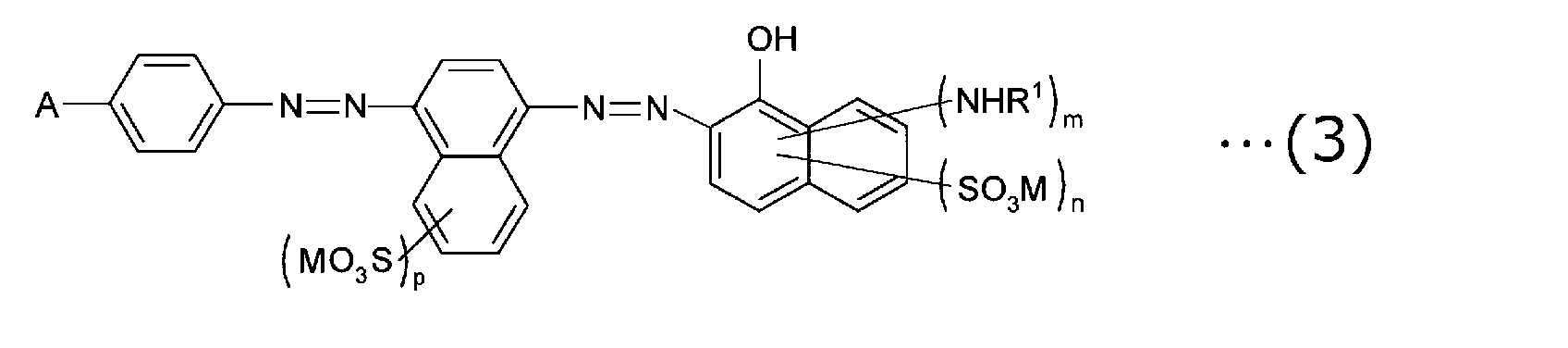
一般式(3)において、R1、M、mおよびnは、上記一般式(1)のそれらと同様であり、Aは、一般式(2)のそれと同様である。一般式(3)において、pは、0~4の整数を表す。前記pは、好ましくは1または2であり、より好ましくは1である。
上記一般式(1)~(3)で表される芳香族ジスアゾ化合物は、例えば、細田豊著「理論製造 染料化学(5版)」(昭和43年7月15日技報堂発行、135頁~152頁)に従って合成できる。例えば、一般式(3)の芳香族ジスアゾ化合物は、アニリン誘導体とナフタレンスルホン酸誘導体をジアゾ化およびカップリング反応させてモノアゾ化合物を得た後、このモノアゾ化合物をジアゾ化した後、さらに、1-アミノ-8-ナフトールスルホン酸誘導体とカップリング反応させることによって合成できる。
偏光子の厚みとしては、目的に応じて任意の適切な厚みが採用され得る。偏光子の厚みの下限は、好ましくは100nmであり、より好ましくは200nmであり、特に好ましくは300nmである。偏光子の厚みの上限は、好ましくは1000nmであり、より好ましくは700nmであり、特に好ましくは500nmである。
偏光子は、例えば下記の工程A~Dを含む方法により形成され得る。
工程A:リオトロピック液晶と溶媒(例えば、水)とを混合し、液晶相(例えば、ネマチック液晶相)を呈する溶液を調製すること;
工程B:基材に配向処理を施すこと;
工程C:配向処理された基材表面に工程Aで得られた溶液を塗布すること;
工程D:塗膜を乾燥すること。
工程A:リオトロピック液晶と溶媒(例えば、水)とを混合し、液晶相(例えば、ネマチック液晶相)を呈する溶液を調製すること;
工程B:基材に配向処理を施すこと;
工程C:配向処理された基材表面に工程Aで得られた溶液を塗布すること;
工程D:塗膜を乾燥すること。
D.粘着剤層
粘着剤層30は、上記のとおり、偏光子20と反対側に配置されたベース粘着剤領域30aと偏光子20側に配置された屈折率調整領域30bとを有する。ベース粘着剤領域30aは、代表的には、粘着剤ベース材料(例えば、通常の粘着剤)で構成され得る。屈折率調整領域30bは、ベース粘着剤領域30aよりも高い屈折率を有する。屈折率調整領域を有する粘着剤層を採用することにより、上記C項に記載の偏光子の優れた特性を維持しつつ、偏光板の反射特性を顕著に改善することができる。
粘着剤層30は、上記のとおり、偏光子20と反対側に配置されたベース粘着剤領域30aと偏光子20側に配置された屈折率調整領域30bとを有する。ベース粘着剤領域30aは、代表的には、粘着剤ベース材料(例えば、通常の粘着剤)で構成され得る。屈折率調整領域30bは、ベース粘着剤領域30aよりも高い屈折率を有する。屈折率調整領域を有する粘着剤層を採用することにより、上記C項に記載の偏光子の優れた特性を維持しつつ、偏光板の反射特性を顕著に改善することができる。
粘着剤ベース材料としては、光学用途に使用可能な粘着性および透明性を有する材料であれば、任意の適切な材料が用いられ得る。具体例としては、アクリル系粘着剤、ゴム系粘着剤、シリコーン系粘着剤、ポリエステル系粘着剤、ウレタン系粘着剤、エポキシ系粘着剤、およびポリエーテル系粘着剤が挙げられる。粘着剤ベース材料は、単独で用いてもよく、2種以上を組み合わせて用いてもよい。透明性、加工性および耐久性などの観点から、アクリル系粘着剤が好ましい。粘着剤ベース材料の屈折率は、代表的には、1.40~1.55である。
1つの実施形態においては、屈折率調整領域30bは、粘着剤ベース材料より高い屈折率を有する樹脂材料で構成され得る。このような樹脂材料の屈折率は、例えば1.59~2.04であり得る。このような樹脂材料としては、例えば、スチレン系樹脂、スチレン系モノマーを単量体単位として含む共重合体樹脂が挙げられる。樹脂材料は、例えば、芳香族環含有アクリル系モノマーおよびスチレン系モノマーから選択された少なくとも1種の芳香族環含有共重合性モノマーを単量体単位として含むアクリル系重合体であり得る。このような材料の詳細は、例えば特開2002-173656号公報に記載されている。当該公報の記載は、本明細書に参考として援用される。屈折率調整領域は、例えば、このような樹脂材料の溶液または分散液を粘着剤ベース材料で形成された粘着剤層(最終的にベース粘着剤領域となる)の表面に塗布し、乾燥することにより形成され得る。
別の実施形態においては、屈折率調整領域30bは、粘着剤ベース材料に高屈折率材料粒子を分散させることにより形成され得る。高屈折率材料粒子の屈折率は、例えば1.60~2.74であり得る。高屈折率材料粒子の屈折率と粘着剤ベース材料の屈折率との差は、好ましくは0.20~1.30である。高屈折率材料粒子を構成する材料の具体例としては、TiO2、ZrO2、CeO2、Al2O3、BaTiO2、Nb2O5およびSnO2、ならびにこれらの組み合わせが挙げられる。高屈折率材料粒子の平均一次粒子径は、好ましくは3nm~100nmである。屈折率調整領域は、例えば、粘着剤ベース材料で形成された粘着剤層に高屈折率材料粒子を分散させた塗布用処理液を塗布し、高屈折率材料粒子を粘着剤ベース材料に浸透させることにより、粘着剤層の厚み方向の一定領域にわたって形成され得る。このようにして形成された屈折率調整領域の屈折率は、例えば1.60~2.14であり得る。
粘着剤層の厚みとしては、目的に応じて任意の適切な厚みが採用され得る。粘着剤層の厚みは、例えば5μm~500μmであり、好ましくは10μm~300μmであり、より好ましくは20μm~200μmである。このうち、屈折率調整領域の厚みは、好ましくは20nm~600nmであり、より好ましくは20nm~300nmであり、さらに好ましくは20nm~200nmである。ベース粘着剤領域と屈折率調整領域との境界は、図1に示すように不規則な微細凹凸形状となる(ただし、図1は、見やすくするために屈折率調整領域の厚みおよび凹凸が強調されている)。屈折率調整領域の厚みは、複数の位置の厚みの平均により決定される。当該複数の位置のそれぞれの厚みは、高屈折率材料粒子の90%が存在する領域の厚みとして求められる。ベース粘着剤領域の厚みは、粘着剤層の全体厚みから屈折率調整領域の厚みを差し引いて求められる。
粘着剤層の全光線透過率は、高ければ高いほど好ましい。粘着剤層の全光線透過率は、好ましくは80%以上であり、より好ましくは90%以上である。全光線透過率は、JIS K7361に準拠して測定され得る。
屈折率調整領域を含む粘着剤層の詳細は、例えばWO2015/108159に記載されている。当該公報の記載は、本明細書に参考として援用される。
以下、実施例により本発明を具体的に説明するが、本発明はこれらの実施例には限定されない。実施例における各特性の測定方法は以下の通りである。なお、特に明記しない限り、実施例における「部」および「%」は重量基準である。
(1)屈折率
アタゴ社製のアッベ屈折率計を用いて平均屈折率を測定した。
(2)反射率および反射色相
実施例および比較例で得られた偏光板を、粘着剤を介して黒板に貼り合わせた。さらに、偏光板の粘着剤層にガラス板を貼り合わせ、画像表示装置代替品を作製した。得られた画像表示装置代替品について、コニカミノルタ社製の分光測色計「CM-2600d」を用いて反射色相および反射率を測定した。反射率は入射角2°および30°の光について、それぞれ測定した。
アタゴ社製のアッベ屈折率計を用いて平均屈折率を測定した。
(2)反射率および反射色相
実施例および比較例で得られた偏光板を、粘着剤を介して黒板に貼り合わせた。さらに、偏光板の粘着剤層にガラス板を貼り合わせ、画像表示装置代替品を作製した。得られた画像表示装置代替品について、コニカミノルタ社製の分光測色計「CM-2600d」を用いて反射色相および反射率を測定した。反射率は入射角2°および30°の光について、それぞれ測定した。
<実施例1>
1.有機色素(リオトロピック液晶)の合成
4-ニトロアニリンと8-アミノ-2-ナフタレンスルホン酸とを、常法(細田豊著「理論製造 染料化学 第5版」昭和43年7月15日技法堂発行、135ページ~152ページに記載の方法)により、ジアゾ化およびカップリング反応させて、モノアゾ化合物を得た。得られたモノアゾ化合物を、上記常法によりジアゾ化し、さらに、1-アミノ-8-ナフトール-2,4-ジスルホン酸リチウム塩とカップリング反応させて粗生成物を得た。これを塩化リチウムで塩析することによって、下記構造式(4)の芳香族ジスアゾ化合物を得た。
1.有機色素(リオトロピック液晶)の合成
4-ニトロアニリンと8-アミノ-2-ナフタレンスルホン酸とを、常法(細田豊著「理論製造 染料化学 第5版」昭和43年7月15日技法堂発行、135ページ~152ページに記載の方法)により、ジアゾ化およびカップリング反応させて、モノアゾ化合物を得た。得られたモノアゾ化合物を、上記常法によりジアゾ化し、さらに、1-アミノ-8-ナフトール-2,4-ジスルホン酸リチウム塩とカップリング反応させて粗生成物を得た。これを塩化リチウムで塩析することによって、下記構造式(4)の芳香族ジスアゾ化合物を得た。
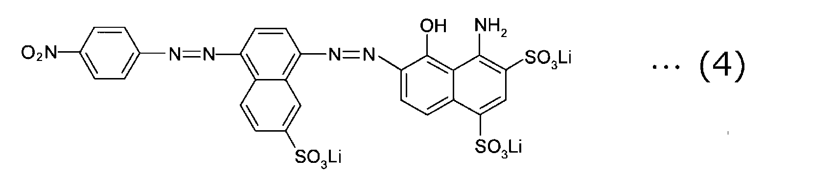
2.偏光子の作製
上記構造式(4)の芳香族ジスアゾ化合物をイオン交換水に溶解させ、濃度4重量%のコーティング液を調製した。当該コーティング液はネマチック液晶相を呈した。一方、基材としてノルボルネン系樹脂フィルム(日本ゼオン(株)製:製品名「ゼオノア」、Re(550)=1nm、Rth(550)=3nm)を用意し、このフィルムの表面にラビング処理および親水化処理(コロナ処理)を施した。当該処理面に、バーコーター(BUSHMAN社製:製品名「Mayer rot HS4」を用いてコーティング液を塗布し、塗膜を23℃の恒温室内で自然乾燥して、基材表面に乾燥塗膜(偏光子)を形成した。得られた偏光子の厚みは300nmであり、na(450)は1.4であり、na(650)は2.7であった。
上記構造式(4)の芳香族ジスアゾ化合物をイオン交換水に溶解させ、濃度4重量%のコーティング液を調製した。当該コーティング液はネマチック液晶相を呈した。一方、基材としてノルボルネン系樹脂フィルム(日本ゼオン(株)製:製品名「ゼオノア」、Re(550)=1nm、Rth(550)=3nm)を用意し、このフィルムの表面にラビング処理および親水化処理(コロナ処理)を施した。当該処理面に、バーコーター(BUSHMAN社製:製品名「Mayer rot HS4」を用いてコーティング液を塗布し、塗膜を23℃の恒温室内で自然乾燥して、基材表面に乾燥塗膜(偏光子)を形成した。得られた偏光子の厚みは300nmであり、na(450)は1.4であり、na(650)は2.7であった。
3.屈折率調整領域を含む粘着剤層の形成
3-1.粘着剤ベース材料の調製
ジシクロペンタニルアクリレート(DCPMA、メタクリル酸ジシクロペンタニル)60重量部、メチルメタクリレート(MMA、メタクリル酸メチル)40重量部、連鎖移動剤としてのα-チオグリセロール3.5重量部、および重合溶媒としてのトルエン100重量部を、4つ口フラスコに投入し、これらを窒素雰囲気下において70℃で1時間撹拌した。次に、重合開始剤としての2,2´-アゾビスイソブチロニトリル0.2重量部を4つ口フラスコに投入し、70℃で2時間反応させ、続いて、80℃で2時間反応させた。その後、反応液を130℃温度雰囲気下に投入し、トルエン、連鎖移動剤および未反応モノマーを乾燥除去させ、固形状のアクリル系ポリマー(A-1)を得た。このアクリル系ポリマー(A-1)の重量平均分子量(Mw)は5.1×10³であった。
一方、アクリル酸2-エチルヘキシル(2EHA)68重量部、N-ビニル-2-ピロリドン(NVP)14.5重量部、およびアクリル酸2-ヒドロキシエチル(HEA)17.5重量部から構成されるモノマー混合物に、光重合開始剤(商品名「イルガキュア184」、BASF社製)0.035重量部、および光重合開始剤(商品名「イルガキュア651」、BASF社製)0.035重量部を配合した後、粘度(計測条件:BH粘度計No.5ローター、10rpm、測定温度30℃)が約20Pa・sになるまで紫外線を照射して、上記モノマー成分の一部が重合したプレポリマー組成物を得た。
3-1.粘着剤ベース材料の調製
ジシクロペンタニルアクリレート(DCPMA、メタクリル酸ジシクロペンタニル)60重量部、メチルメタクリレート(MMA、メタクリル酸メチル)40重量部、連鎖移動剤としてのα-チオグリセロール3.5重量部、および重合溶媒としてのトルエン100重量部を、4つ口フラスコに投入し、これらを窒素雰囲気下において70℃で1時間撹拌した。次に、重合開始剤としての2,2´-アゾビスイソブチロニトリル0.2重量部を4つ口フラスコに投入し、70℃で2時間反応させ、続いて、80℃で2時間反応させた。その後、反応液を130℃温度雰囲気下に投入し、トルエン、連鎖移動剤および未反応モノマーを乾燥除去させ、固形状のアクリル系ポリマー(A-1)を得た。このアクリル系ポリマー(A-1)の重量平均分子量(Mw)は5.1×10³であった。
一方、アクリル酸2-エチルヘキシル(2EHA)68重量部、N-ビニル-2-ピロリドン(NVP)14.5重量部、およびアクリル酸2-ヒドロキシエチル(HEA)17.5重量部から構成されるモノマー混合物に、光重合開始剤(商品名「イルガキュア184」、BASF社製)0.035重量部、および光重合開始剤(商品名「イルガキュア651」、BASF社製)0.035重量部を配合した後、粘度(計測条件:BH粘度計No.5ローター、10rpm、測定温度30℃)が約20Pa・sになるまで紫外線を照射して、上記モノマー成分の一部が重合したプレポリマー組成物を得た。
3-2.粘着剤層(ベース粘着剤領域)の形成
次に、上記プレポリマー組成物に、上記アクリル系ポリマー(A-1)5重量部、ヘキサンジオールジアクリレート(HDDA)0.15重量部、シランカップリング剤(商品名「KBM-403」、信越化学工業株式会社製)0.3重量部を添加して混合し、アクリル系粘着剤組成物を得た。上記アクリル系粘着剤組成物を、剥離フィルム(商品名「MRF#38」、三菱樹脂株式会社製)の剥離処理面に、粘着剤層形成後の厚さが150μmとなるように塗布して、塗布層を形成し、次いで、当該塗布層の表面に、剥離フィルム(商品名「MRN#38」、三菱樹脂株式会社製)を貼り合わせた。その後、照度:5mW/cm2、光量:1500mJ/cm2の条件で紫外線照射を行い、塗布層を光硬化させて、粘着剤層(屈折率:1.48)を形成した。
次に、上記プレポリマー組成物に、上記アクリル系ポリマー(A-1)5重量部、ヘキサンジオールジアクリレート(HDDA)0.15重量部、シランカップリング剤(商品名「KBM-403」、信越化学工業株式会社製)0.3重量部を添加して混合し、アクリル系粘着剤組成物を得た。上記アクリル系粘着剤組成物を、剥離フィルム(商品名「MRF#38」、三菱樹脂株式会社製)の剥離処理面に、粘着剤層形成後の厚さが150μmとなるように塗布して、塗布層を形成し、次いで、当該塗布層の表面に、剥離フィルム(商品名「MRN#38」、三菱樹脂株式会社製)を貼り合わせた。その後、照度:5mW/cm2、光量:1500mJ/cm2の条件で紫外線照射を行い、塗布層を光硬化させて、粘着剤層(屈折率:1.48)を形成した。
3-3.屈折率調整領域の形成
高屈折率材料粒子を分散させた塗布用処理液として、CIKナノテック(株)製の分散液を用いた。当該分散液は、ジルコニア粒子(ZrO2、屈折率:2.17、平均一次粒子径:20nm)をエタノールに分散させた分散液(粒子濃度:1.5重量%、分散液の透過率:75%)であった。なお、ジルコニア粒子の平均一次粒子径は、TEM画像から計測した。
上記3-2で得られた両面に剥離フィルムが仮着された粘着剤層(粘着剤シート)から、一方の剥離フィルムを剥離除去した。露出した粘着剤層の表面に、上記塗布用処理液を、屈折率調整領域の厚さが20nm~300nmになるようにバーコーターRDS No.5で塗布し、110℃の乾燥オーブンで180秒間乾燥させた。このようにして、屈折率調整領域(屈折率:1.62)を形成した。次いで、屈折率調整領域が形成された粘着剤層表面に剥離フィルムを貼り合わせ、粘着剤シートを得た。
高屈折率材料粒子を分散させた塗布用処理液として、CIKナノテック(株)製の分散液を用いた。当該分散液は、ジルコニア粒子(ZrO2、屈折率:2.17、平均一次粒子径:20nm)をエタノールに分散させた分散液(粒子濃度:1.5重量%、分散液の透過率:75%)であった。なお、ジルコニア粒子の平均一次粒子径は、TEM画像から計測した。
上記3-2で得られた両面に剥離フィルムが仮着された粘着剤層(粘着剤シート)から、一方の剥離フィルムを剥離除去した。露出した粘着剤層の表面に、上記塗布用処理液を、屈折率調整領域の厚さが20nm~300nmになるようにバーコーターRDS No.5で塗布し、110℃の乾燥オーブンで180秒間乾燥させた。このようにして、屈折率調整領域(屈折率:1.62)を形成した。次いで、屈折率調整領域が形成された粘着剤層表面に剥離フィルムを貼り合わせ、粘着剤シートを得た。
4.偏光板の作製
上記2で得られた基材/偏光子の積層体の偏光子表面に、上記3-3で得られた粘着剤シートを、屈折率調整領域が偏光子側となるようにして貼り合わせた。このようにして、基材/偏光子/屈折率調整領域/ベース粘着剤領域の構成を有する偏光板を得た。得られた偏光板を上記(2)の評価に供した。結果を表1に示す。
上記2で得られた基材/偏光子の積層体の偏光子表面に、上記3-3で得られた粘着剤シートを、屈折率調整領域が偏光子側となるようにして貼り合わせた。このようにして、基材/偏光子/屈折率調整領域/ベース粘着剤領域の構成を有する偏光板を得た。得られた偏光板を上記(2)の評価に供した。結果を表1に示す。
<比較例1>
粘着剤層に屈折率調整領域を形成しなかったこと以外は実施例1と同様にして偏光板を作製した。得られた偏光板を用いて実施例1と同様の評価を行った。結果を表1に示す。
粘着剤層に屈折率調整領域を形成しなかったこと以外は実施例1と同様にして偏光板を作製した。得られた偏光板を用いて実施例1と同様の評価を行った。結果を表1に示す。

<評価>
表1から明らかなように、高屈折率層(実施例では粘着剤層における屈折率調整領域)を形成することにより、反射色相がよりニュートラルとなり、反射率を抑制することができることがわかる。
表1から明らかなように、高屈折率層(実施例では粘着剤層における屈折率調整領域)を形成することにより、反射色相がよりニュートラルとなり、反射率を抑制することができることがわかる。
本発明の偏光板は、携帯情報端末(PDA),携帯電話,時計,デジタルカメラ,携帯ゲーム機などの携帯機器、パソコンモニター,ノートパソコン,コピー機などのOA機器、ビデオカメラ,液晶テレビ,電子レンジなどの家庭用電気機器、インストゥルメントパネル、バックモニター,カーナビゲーションシステム用モニター,カーオーディオなどの車載用機器、商業店舗用インフォメーション用モニターなどの展示機器、監視用モニターなどの警備機器、介護用モニター,医療用モニターなどの介護・医療機器などの各種用途の画像表示装置に用いることができる。
10 基材
20 偏光子
30 粘着剤層
30a ベース粘着剤領域
30b 屈折率調整領域
100 偏光板
20 偏光子
30 粘着剤層
30a ベース粘着剤領域
30b 屈折率調整領域
100 偏光板
Claims (7)
- 基材と偏光子と高屈折率層とをこの順に有し、
該偏光子の吸収軸方向の屈折率をna、透過軸方向の屈折率をntとしたとき、少なくともnaが波長依存性を有する、
偏光板。 - 前記高屈折率層が、粘着剤層における屈折率調整領域として形成されている、請求項1に記載の偏光板。
- 波長450nmにおける前記偏光子の吸収軸方向の屈折率na(450)と波長650nmにおける該偏光子の吸収軸方向の屈折率na(650)との差の絶対値が1.0以上である、請求項1または2に記載の偏光板。
- 前記屈折率調整領域の屈折率が1.60~2.14である、請求項1から3のいずれかに記載の偏光板。
- 前記偏光子の吸収軸方向の反射率と該偏光子の透過軸方向の反射率との差が10%以上である、請求項1から4のいずれかに記載の偏光板。
- 前記偏光子が芳香族ジスアゾ化合物を含む、請求項1から5のいずれかに記載の偏光板。
- 前記偏光子の厚みが1000nm以下である、請求項6に記載の偏光板。
Priority Applications (2)
| Application Number | Priority Date | Filing Date | Title |
|---|---|---|---|
| KR1020197025359A KR20190126071A (ko) | 2017-03-15 | 2018-02-20 | 편광판 |
| CN201880017466.9A CN110392851B (zh) | 2017-03-15 | 2018-02-20 | 偏振片 |
Applications Claiming Priority (2)
| Application Number | Priority Date | Filing Date | Title |
|---|---|---|---|
| JP2017049744A JP7048213B2 (ja) | 2017-03-15 | 2017-03-15 | 偏光板 |
| JP2017-049744 | 2017-03-15 |
Publications (1)
| Publication Number | Publication Date |
|---|---|
| WO2018168351A1 true WO2018168351A1 (ja) | 2018-09-20 |
Family
ID=63521991
Family Applications (1)
| Application Number | Title | Priority Date | Filing Date |
|---|---|---|---|
| PCT/JP2018/005940 Ceased WO2018168351A1 (ja) | 2017-03-15 | 2018-02-20 | 偏光板 |
Country Status (5)
| Country | Link |
|---|---|
| JP (1) | JP7048213B2 (ja) |
| KR (1) | KR20190126071A (ja) |
| CN (1) | CN110392851B (ja) |
| TW (1) | TWI762601B (ja) |
| WO (1) | WO2018168351A1 (ja) |
Cited By (1)
| Publication number | Priority date | Publication date | Assignee | Title |
|---|---|---|---|---|
| WO2019151334A1 (ja) * | 2018-01-30 | 2019-08-08 | 富士フイルム株式会社 | 偏光板、円偏光板、表示装置 |
Families Citing this family (1)
| Publication number | Priority date | Publication date | Assignee | Title |
|---|---|---|---|---|
| JP7557504B2 (ja) | 2022-08-17 | 2024-09-27 | 日東電工株式会社 | 偏光板および該偏光板を用いた画像表示装置 |
Citations (10)
| Publication number | Priority date | Publication date | Assignee | Title |
|---|---|---|---|---|
| JP2004133171A (ja) * | 2002-10-10 | 2004-04-30 | Konica Minolta Holdings Inc | 光学補償シート及び液晶表示装置 |
| KR20060001238A (ko) * | 2004-06-30 | 2006-01-06 | 엘지.필립스 엘시디 주식회사 | 편광필름 및 액정표시장치 |
| JP2010134349A (ja) * | 2008-12-08 | 2010-06-17 | Sony Corp | 液晶表示装置 |
| JP2012068377A (ja) * | 2010-09-22 | 2012-04-05 | Toppan Printing Co Ltd | 反射防止フィルム、偏光板および透過型液晶表示装置 |
| JP2014215592A (ja) * | 2013-04-30 | 2014-11-17 | コニカミノルタ株式会社 | 偏光機能付きガラスおよびそれを備えた液晶表示装置 |
| JP2015200866A (ja) * | 2014-03-31 | 2015-11-12 | 日東電工株式会社 | 光学部材、偏光板のセットおよび液晶表示装置 |
| WO2015194532A1 (ja) * | 2014-06-18 | 2015-12-23 | 王子ホールディングス株式会社 | 偏光子用粘着剤組成物及び偏光子用粘着シート |
| JP2016012124A (ja) * | 2014-06-06 | 2016-01-21 | 日東電工株式会社 | 投影装置及び車 |
| JP2016206468A (ja) * | 2015-04-24 | 2016-12-08 | 株式会社ポラテクノ | 光学フィルタ並びにそれを使用した撮像装置及び画像形成装置 |
| JP2017026826A (ja) * | 2015-07-22 | 2017-02-02 | 日東電工株式会社 | 透明な粘着剤層及びパターン化された透明導電層を有する偏光フィルム積層体並びに液晶パネル及び有機elパネル |
Family Cites Families (3)
| Publication number | Priority date | Publication date | Assignee | Title |
|---|---|---|---|---|
| JPS6055878B2 (ja) | 1976-07-06 | 1985-12-06 | オムロン株式会社 | 取引処理装置の警備設備 |
| JP5153445B2 (ja) * | 2008-01-24 | 2013-02-27 | 日東電工株式会社 | 液晶性コーティング液および偏光膜 |
| JP6152068B2 (ja) * | 2014-04-09 | 2017-06-21 | 富士フイルム株式会社 | 偏光板、および画像表示装置 |
-
2017
- 2017-03-15 JP JP2017049744A patent/JP7048213B2/ja not_active Expired - Fee Related
-
2018
- 2018-02-20 WO PCT/JP2018/005940 patent/WO2018168351A1/ja not_active Ceased
- 2018-02-20 KR KR1020197025359A patent/KR20190126071A/ko not_active Abandoned
- 2018-02-20 CN CN201880017466.9A patent/CN110392851B/zh active Active
- 2018-03-14 TW TW107108586A patent/TWI762601B/zh not_active IP Right Cessation
Patent Citations (10)
| Publication number | Priority date | Publication date | Assignee | Title |
|---|---|---|---|---|
| JP2004133171A (ja) * | 2002-10-10 | 2004-04-30 | Konica Minolta Holdings Inc | 光学補償シート及び液晶表示装置 |
| KR20060001238A (ko) * | 2004-06-30 | 2006-01-06 | 엘지.필립스 엘시디 주식회사 | 편광필름 및 액정표시장치 |
| JP2010134349A (ja) * | 2008-12-08 | 2010-06-17 | Sony Corp | 液晶表示装置 |
| JP2012068377A (ja) * | 2010-09-22 | 2012-04-05 | Toppan Printing Co Ltd | 反射防止フィルム、偏光板および透過型液晶表示装置 |
| JP2014215592A (ja) * | 2013-04-30 | 2014-11-17 | コニカミノルタ株式会社 | 偏光機能付きガラスおよびそれを備えた液晶表示装置 |
| JP2015200866A (ja) * | 2014-03-31 | 2015-11-12 | 日東電工株式会社 | 光学部材、偏光板のセットおよび液晶表示装置 |
| JP2016012124A (ja) * | 2014-06-06 | 2016-01-21 | 日東電工株式会社 | 投影装置及び車 |
| WO2015194532A1 (ja) * | 2014-06-18 | 2015-12-23 | 王子ホールディングス株式会社 | 偏光子用粘着剤組成物及び偏光子用粘着シート |
| JP2016206468A (ja) * | 2015-04-24 | 2016-12-08 | 株式会社ポラテクノ | 光学フィルタ並びにそれを使用した撮像装置及び画像形成装置 |
| JP2017026826A (ja) * | 2015-07-22 | 2017-02-02 | 日東電工株式会社 | 透明な粘着剤層及びパターン化された透明導電層を有する偏光フィルム積層体並びに液晶パネル及び有機elパネル |
Cited By (2)
| Publication number | Priority date | Publication date | Assignee | Title |
|---|---|---|---|---|
| WO2019151334A1 (ja) * | 2018-01-30 | 2019-08-08 | 富士フイルム株式会社 | 偏光板、円偏光板、表示装置 |
| US11054691B2 (en) | 2018-01-30 | 2021-07-06 | Fujifilm Corporation | Polarizing plate, circularly polarizing plate, and display device |
Also Published As
| Publication number | Publication date |
|---|---|
| JP7048213B2 (ja) | 2022-04-05 |
| TWI762601B (zh) | 2022-05-01 |
| CN110392851B (zh) | 2022-05-17 |
| KR20190126071A (ko) | 2019-11-08 |
| JP2018151603A (ja) | 2018-09-27 |
| TW201837508A (zh) | 2018-10-16 |
| CN110392851A (zh) | 2019-10-29 |
Similar Documents
| Publication | Publication Date | Title |
|---|---|---|
| KR102458585B1 (ko) | 원편광판 및 표시 장치 | |
| TW201730597A (zh) | 偏光板、具備該偏光板的顯示裝置,及其製造方法 | |
| JP7553474B2 (ja) | 光吸収異方性層、積層体、光学フィルム、画像表示装置、バックライトモジュール | |
| JP7573609B2 (ja) | 光学フィルム、光学積層体および画像表示装置 | |
| JPWO2017175581A1 (ja) | 光反射フィルム、ならびにこれを用いた光制御フィルムおよびミラーディスプレイ | |
| JP5723077B1 (ja) | 位相差板、楕円偏光板およびそれを用いた表示装置 | |
| JP7835725B2 (ja) | 積層体、映り込み防止システム、および、画像表示装置 | |
| WO2021187379A1 (ja) | 液晶表示装置 | |
| WO2022270466A1 (ja) | 光学フィルム、光吸収異方性層の製造方法および画像表示装置 | |
| JP5274928B2 (ja) | 液晶パネル及び液晶表示装置 | |
| JP7048213B2 (ja) | 偏光板 | |
| JP7281953B2 (ja) | 積層体 | |
| WO2022234789A1 (ja) | 偏光板及び有機el表示装置 | |
| JP2024180789A (ja) | 光学積層体及び画像表示装置 | |
| CN118584572A (zh) | 光学层叠体 | |
| JP7723855B1 (ja) | 偏光積層体 | |
| JP2016085304A (ja) | 位相差板およびその製造方法、並びに位相差板を用いた楕円偏光板および表示装置 | |
| JP7520197B2 (ja) | 光学積層体及びその製造方法 | |
| KR102863763B1 (ko) | 유기 el 표시 장치 | |
| CN120722480A (zh) | 光学层叠体和光学层叠体的制造方法 | |
| TW202612909A (zh) | 偏光積層體 | |
| JP2026008879A (ja) | 光学積層体、及び、画像表示装置 | |
| JP2025168252A (ja) | 位相差層積層体及び光学積層体 | |
| JP2026008790A (ja) | 位相差層積層体、光学積層体、及び、位相差層積層体の製造方法 | |
| TW202409620A (zh) | 圓偏光板 |
Legal Events
| Date | Code | Title | Description |
|---|---|---|---|
| 121 | Ep: the epo has been informed by wipo that ep was designated in this application |
Ref document number: 18767703 Country of ref document: EP Kind code of ref document: A1 |
|
| ENP | Entry into the national phase |
Ref document number: 20197025359 Country of ref document: KR Kind code of ref document: A |
|
| NENP | Non-entry into the national phase |
Ref country code: DE |
|
| 122 | Ep: pct application non-entry in european phase |
Ref document number: 18767703 Country of ref document: EP Kind code of ref document: A1 |