WO2018168124A1 - 制御装置、プログラム、支援装置および支援方法 - Google Patents
制御装置、プログラム、支援装置および支援方法 Download PDFInfo
- Publication number
- WO2018168124A1 WO2018168124A1 PCT/JP2017/044487 JP2017044487W WO2018168124A1 WO 2018168124 A1 WO2018168124 A1 WO 2018168124A1 JP 2017044487 W JP2017044487 W JP 2017044487W WO 2018168124 A1 WO2018168124 A1 WO 2018168124A1
- Authority
- WO
- WIPO (PCT)
- Prior art keywords
- pedal
- mode
- actuator
- vehicle speed
- driver
- Prior art date
- Legal status (The legal status is an assumption and is not a legal conclusion. Google has not performed a legal analysis and makes no representation as to the accuracy of the status listed.)
- Ceased
Links
Images




Classifications
-
- B—PERFORMING OPERATIONS; TRANSPORTING
- B60—VEHICLES IN GENERAL
- B60K—ARRANGEMENT OR MOUNTING OF PROPULSION UNITS OR OF TRANSMISSIONS IN VEHICLES; ARRANGEMENT OR MOUNTING OF PLURAL DIVERSE PRIME-MOVERS IN VEHICLES; AUXILIARY DRIVES FOR VEHICLES; INSTRUMENTATION OR DASHBOARDS FOR VEHICLES; ARRANGEMENTS IN CONNECTION WITH COOLING, AIR INTAKE, GAS EXHAUST OR FUEL SUPPLY OF PROPULSION UNITS IN VEHICLES
- B60K26/00—Arrangement or mounting of propulsion-unit control devices in vehicles
- B60K26/04—Arrangement or mounting of propulsion-unit control devices in vehicles of means connecting initiating means or elements to propulsion unit
-
- B—PERFORMING OPERATIONS; TRANSPORTING
- B60—VEHICLES IN GENERAL
- B60K—ARRANGEMENT OR MOUNTING OF PROPULSION UNITS OR OF TRANSMISSIONS IN VEHICLES; ARRANGEMENT OR MOUNTING OF PLURAL DIVERSE PRIME-MOVERS IN VEHICLES; AUXILIARY DRIVES FOR VEHICLES; INSTRUMENTATION OR DASHBOARDS FOR VEHICLES; ARRANGEMENTS IN CONNECTION WITH COOLING, AIR INTAKE, GAS EXHAUST OR FUEL SUPPLY OF PROPULSION UNITS IN VEHICLES
- B60K31/00—Vehicle fittings, acting on a single sub-unit only, for automatically controlling vehicle speed, i.e. preventing speed from exceeding an arbitrarily established velocity or maintaining speed at a particular velocity, as selected by the vehicle operator
-
- B—PERFORMING OPERATIONS; TRANSPORTING
- B60—VEHICLES IN GENERAL
- B60W—CONJOINT CONTROL OF VEHICLE SUB-UNITS OF DIFFERENT TYPE OR DIFFERENT FUNCTION; CONTROL SYSTEMS SPECIALLY ADAPTED FOR HYBRID VEHICLES; ROAD VEHICLE DRIVE CONTROL SYSTEMS FOR PURPOSES NOT RELATED TO THE CONTROL OF A PARTICULAR SUB-UNIT
- B60W30/00—Purposes of road vehicle drive control systems not related to the control of a particular sub-unit, e.g. of systems using conjoint control of vehicle sub-units
- B60W30/14—Adaptive cruise control
-
- B—PERFORMING OPERATIONS; TRANSPORTING
- B60—VEHICLES IN GENERAL
- B60W—CONJOINT CONTROL OF VEHICLE SUB-UNITS OF DIFFERENT TYPE OR DIFFERENT FUNCTION; CONTROL SYSTEMS SPECIALLY ADAPTED FOR HYBRID VEHICLES; ROAD VEHICLE DRIVE CONTROL SYSTEMS FOR PURPOSES NOT RELATED TO THE CONTROL OF A PARTICULAR SUB-UNIT
- B60W50/00—Details of control systems for road vehicle drive control not related to the control of a particular sub-unit, e.g. process diagnostic or vehicle driver interfaces
- B60W50/08—Interaction between the driver and the control system
- B60W50/10—Interpretation of driver requests or demands
Definitions
- This invention relates to a technique for switching a vehicle operation mode between a manual operation mode and an automatic operation mode.
- the automatic driving mode is a mode in which the vehicle is driven mainly by a computer, and is distinguished from a manual driving mode in which a driver (driver) operates the vehicle depending on his / her limbs and senses.
- the automatic driving mode is expected to bring about effects such as reducing the driver's burden and reducing traffic congestion.
- the driver may have to drive with the steering wheel.
- it may be better to use the automatic operation mode on a highway, but to use the manual operation mode on a general road. Therefore, a technique for safely switching between the automatic operation mode and the manual operation mode is required.
- the operation of the driver and the behavior of the vehicle are basically separated. In other words, except for emergency response, the vehicle is not affected even if the steering wheel is turned off or the accelerator or brake is depressed. Conversely, in the manual operation mode, the driver's operation is directly transmitted to the vehicle. Since the operation feeling is remarkably different in this way, the safety depends on how smoothly the operation can be transferred from the computer to the human when the operation mode is switched.
- Japanese Patent Application Laid-Open No. 2015-182525 discloses a technique aiming at a smooth change to the speed required by the driver when switching to manual operation. However, there is no discussion about the needs from another point of view, how to smoothly take over pedal operation while maintaining speed.
- Handing over includes handing over the steering wheel, handing over the pedal, and handing over the visual, but there is a demand for technical development related to pedaling.
- the present invention has been made paying attention to the above circumstances, and an object thereof is to allow the driver to smoothly take over the pedal operation, thereby improving safety.
- the present invention takes the following measures.
- the 1st aspect of this invention is a control apparatus provided in the assistance apparatus which assists a driver
- the first mode is a mode in which the operation amount of the pedal for vehicle speed control is not related to the vehicle speed
- the second mode is a mode in which the operation amount is related to the vehicle speed.
- the control device includes a holding unit that holds the pedal in a default position by controlling an actuator that generates a driving force and positions the pedal in response to the start of switching from the first mode to the second mode.
- Pedal control that controls the actuator to move the pedal to the position corresponding to the vehicle speed when the footrest is detected by the detector that detects the driver's footrest on the pedal while And a release portion for releasing the pedal that is stepped on at a position corresponding to the vehicle speed from the driving force of the actuator.
- the release unit is configured to release the pedal from the driving force of the actuator with a time constant set to a value that the driver can follow.
- the default position is configured such that the pedal is not depressed in the second mode.
- the default position is configured to be a stepping position corresponding to the accelerator opening calculated from the legal speed set on the road on which the vehicle is traveling.
- the detector is configured to be a sensor that detects a load on the pedal.
- the detector is configured to be an image sensor that detects footrest on the pedal by analyzing video data obtained by photographing an area including the pedal.
- the pedal controller is configured to notify the driver whether the pedal is an accelerator pedal or a brake pedal when controlling the actuator.
- the accelerator pedal is held at the default position by the actuator. From this state, when the footrest on the pedal is detected, the pedal is moved to a position corresponding to the vehicle speed. Thereafter, the pedal that is stepped on at a position corresponding to the vehicle speed is released from the driving force of the actuator.
- the pedal is initially in a predetermined position, and when the driver puts his / her foot on, the pedal is moved to the vehicle speed corresponding position with the foot on. Thereafter, the pedal positioning force (driving force) is released, and the driver can take over the pedal operation from the position corresponding to the vehicle speed. Therefore, the driver can take over the depression of the pedal at an appropriate position, thereby improving the safety related to the mode switching.
- the pedal is released.
- the unit is released from the driving force of the actuator with a time constant set to a value that the driver can follow. Because of this configuration, the pedal operation is gradually handed over from the machine to the human foot rather than as soon as the foot is placed.
- the driver may be given an announcement such as "Start pedal takeover".
- the driver feels that the force for positioning the pedal gradually decreases, and keeps the position of the pedal following that.
- the pedal operation can be taken over in a state where the balance of the force for operating the pedal is maintained, the safety related to the mode switching can be improved.
- the default position is a position where the pedal is not depressed in the second mode.
- the pedal is initially in the foremost position, and the accelerator amount is 0 for an accelerator pedal, and the brake amount is 0 for a brake pedal. Since it is such a structure, a driver
- operator is easy to put a foot rather than having a pedal in the back.
- the default position is a depression position corresponding to the accelerator opening calculated from the legal speed set on the road on which the vehicle is traveling.
- the footrest on the pedal is detected by the sensor that detects the load on the pedal. Since it is such a structure, the footrest on a pedal can be detected by a simple means.
- the footrest on the pedal is detected by the image sensor that analyzes the video data obtained by photographing the area including the pedal. Since it is such a structure, since it is not necessary to attach a sensor to pedal itself, weight reduction of a pedal can be promoted.
- the handover process is started after the driver is notified whether the pedal to be handed over is an accelerator pedal or a brake pedal. Therefore, the driver can surely recognize the pedal to be handed over.
- FIG. 1 is a diagram illustrating an overall configuration of an automatic driving control system including a support device according to an embodiment of the present invention.
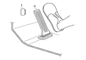
- FIG. 2 is an external view showing an example of the vicinity of the accelerator pedal 10 on the driver's seat side floor.
- FIG. 3 is an external view showing an example of a driver seat.
- FIG. 4 is a functional block diagram showing an example of the pedal ECU 5 shown in FIG.
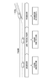
- FIG. 5 is a diagram for explaining one of the concepts related to mode switching.
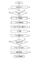
- FIG. 6 is a flowchart illustrating an example of a processing procedure according to the embodiment.
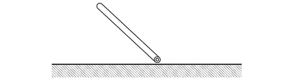
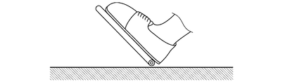
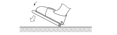
- FIG. 7A is a schematic diagram showing a change in the position of the accelerator pedal 10 during mode switching.
- FIG. 7B is a schematic diagram showing a change in the position of the accelerator pedal 10 during mode switching.
- FIG. 7C is a schematic diagram showing a change in the position of the accelerator pedal 10 during mode switching.
- FIG. 7D is a schematic diagram showing a change in the position of the accelerator pedal 10 during mode
- FIG. 1 is a block diagram showing an example of an automatic driving control system including a support device according to an embodiment of the present invention.
- This automatic driving control system is mounted on the vehicle 1.
- the vehicle 1 can travel in either the manual operation mode or the automatic operation mode.
- the mode switching control device 6 performs control related to the mode switching.
- the vehicle 1 includes a power unit 2 and a steering device 3 as basic equipment.
- the power unit 2 includes a power source and a transmission.
- As the power source an internal combustion engine, an electric motor, or both can be used.
- the steering device 3 is connected to the steering wheel 4.
- the automatic driving mode is a mode that realizes an operating state in which the vehicle 1 automatically travels along the road, for example.
- the automatic driving mode may include, for example, a driving state in which the vehicle 1 automatically travels toward a preset destination without driving by the driver. In the automatic driving mode, it is not always necessary to control all the behaviors of the vehicle 1.
- the automatic driving mode may include a driving state in which the driving operation of the driver is reflected in the traveling of the vehicle 1 within a preset allowable range. In this embodiment, it is assumed that the pedal operation amount for vehicle speed control is not related to the vehicle speed in the automatic operation mode.
- the driving operation support control assists the driving operation of the vehicle 1 so as to drive along the curve by assisting the steering by the driver when the vehicle 1 is traveling on the curve, for example.
- the driving operation support control includes control for assisting the driver's accelerator operation (for example, operation of the accelerator pedal) or brake operation (for example, operation of the brake pedal), manual steering (manual operation of steering), and manual speed adjustment (speed adjustment). Manual operation) or the like.
- Manual steering is to operate the traveling direction of the vehicle 1 mainly by the driver's operation of the steering wheel.
- the manual speed adjustment is to adjust the speed of the vehicle 1 mainly by the driver's accelerator operation or brake operation.
- the manual operation mode is a mode in which the vehicle 1 is driven mainly by a driver's manual driving operation, for example.
- the manual operation mode is, for example, an operation mode in which the vehicle 1 travels based only on the driving operation of the driver and an operation mode in which driving operation support control is performed to assist the driving operation of the driver while mainly driving the driving operation of the driver. And may be included.
- description will be made assuming that the pedal operation amount for vehicle speed control is related to the vehicle speed in the manual operation mode.
- Automatic control includes, for example, automatic steering (automatic steering operation) and automatic speed adjustment (automatic driving of speed).
- Automatic steering is an operating state in which the steering device is automatically controlled.
- Automatic steering includes LKA (Lane Keeping Assist).
- LKA Li Keeping Assist
- the LKA automatically controls the steering device 3 so that the vehicle 1 does not deviate from the traveling lane even when the driver does not perform the steering operation.
- the driver's steering operation may be reflected in the steering of the vehicle 1 within a range (allowable range) in which the vehicle 1 does not deviate from the travel lane even during execution of LKA.
- automatic steering is not limited to LKA.
- Automatic speed adjustment is an operating state in which the speed of the vehicle 1 is automatically controlled.
- Automatic speed adjustment includes ACC (Adaptive Cruise Control). For example, when there is no preceding vehicle ahead of the vehicle 1, the ACC performs constant speed control that causes the vehicle 1 to travel at a constant speed at a preset speed. Further, when a preceding vehicle is present in front of the vehicle 1, the ACC performs follow-up control for adjusting the vehicle speed of the vehicle 1 according to the inter-vehicle distance from the preceding vehicle.
- ACC Adaptive Cruise Control
- the vehicle 1 decelerates if there is a driver's brake operation (for example, operation of a brake pedal). Further, even if the ACC is being executed, if there is an accelerator operation (for example, an accelerator pedal operation) by the driver, a preset maximum permissible speed (for example, the maximum speed legally determined on the running road) ) Until the vehicle 1 can be accelerated. Note that not only ACC but also CC (Cruise Control) is included in the category of automatic speed adjustment.
- the mode switching control device 6 is a computer that executes control related to mode switching for switching the operation mode of the vehicle.
- the mode switching control device 6 is connected to a display unit 9 as an example of a display.
- the display unit 9 displays a map around the vehicle, various information, messages, and the like.
- the display unit 9 is, for example, a touch panel of a car navigation system, a head-up display, a display of a smartphone or a tablet terminal, and the like, and is a human machine interface between a passenger (including a driver) and the mode switching control device 6.
- a speaker (not shown) is also included in this type of human machine interface.
- the mode switching control device 6 is connected to the driver camera 7.
- the driver camera 7 is disposed at a place where the driver can be imaged, for example, on a dashboard, and images the inside of the vehicle including the driver.
- the mode switching control device 6 is connected to the GPS receiver 14.
- the GPS receiver 14 captures a plurality of GPS satellites and calculates three-dimensional position data (positioning information) of the vehicle 1 based on the positioning information transmitted from each satellite. Based on the position data of the vehicle 1 and information from the navigation system (not shown), the mode switching control device 6 determines approach of a switching section related to mode switching. When recognizing that the switching section is approaching, the mode switching control device 6 starts control related to mode switching.
- the switching section is a section of a certain length provided so that the operation mode can be switched with ease. For example, it is conceivable to set a switching section of about 100m to several kilometers before the interchange, etc., and to perform mode switching after the surroundings have been prepared for visual observation and the safety can be sufficiently secured. Yes. A period (also referred to as a switching period) required for traveling in this section is approximately 60 seconds.
- the automatic operation control system in the present embodiment includes a pedal ECU (Electronic Control Unit) 5.
- the pedal ECU 5 is a computer as a control device provided in a support device that assists the driver during mode switching.
- the pedal ECU 5 acquires sensing data from the foot camera 8, the load sensor 11, the pedal sensor 12, the gyro sensor 15, and the vehicle speed sensor 16 via a not-shown in-vehicle LAN (Local Area Network).
- the pedal ECU 5 is communicably connected to the mode switching control device 6 to exchange various data with each other.
- the pedal ECU 5 is communicably connected to an actuator 13 that generates a driving force and positions the accelerator pedal 10, and outputs a control signal for controlling the actuator 13.
- the accelerator pedal 10 is controlled by the pedal ECU 5.
- the system containing pedal ECU5, the foot camera 8 or the load sensor 11, and the actuator 13 as an assistance apparatus which assists a driver
- FIG. 2 is an external view showing an example of the vicinity of the accelerator pedal 10 on the driver's seat side floor.
- the vehicle 1 travels without permission even when the accelerator pedal 10 is released.
- the foot camera 8 is attached to a position that does not interfere with the driver's side floor.
- the foot camera 8 captures a floor portion including the accelerator pedal 10 and analyzes the obtained video data to detect the footrest on the accelerator pedal 10. The result of this detection is notified to the pedal ECU 5.
- FIG. 3 is an external view showing an example of a driver seat.
- the load sensor 11 is attached to, for example, a portion of the seat where the right thigh is placed, and can detect the presence or absence of a passenger by tracing the load or trace the movement of the right foot.
- the detected pressure also changes depending on whether the foot is on the accelerator pedal 10 or not. That is, the load sensor 11 detects the load on the accelerator pedal 10 and notifies the pedal ECU 5 of the presence or absence of footrest based on the result. If both the foot camera 8 and the load sensor 11 are used, they can complement each other, and only one of them can be used as long as sufficient sensing accuracy can be obtained.
- FIG. 4 is a functional block diagram illustrating an example of the pedal ECU 5.
- the pedal ECU 5 includes an I / O (input / output interface) 51, a control unit 52, and a memory 53.
- the memory 53 is a semiconductor memory such as RAM (Random Access Memory), ROM (Read Only Memory), flash memory, SDRAM (Synchronous Dynamic RAM), EPROM (Erasable Programmable ROM), EPROM (Electrically Erasable Programmable ROM), etc. It may be a non-volatile memory or a storage medium such as an SSD (Solid State Drive) or HDD (Hard Disk Drive). Alternatively, it may be a storage area provided inside a one-chip microcomputer such as an FPGA (Field Programmable Gate Array) or a PIC (Peripheral Interface Controller).
- FPGA Field Programmable Gate Array
- PIC Peripheral Interface Controller
- the I / O 51 acquires operation amount data of the accelerator pedal 10 from the pedal sensor 12.
- the operation amount data is data indicating the position of the accelerator pedal 10 or the accelerator opening (depression amount), and is an amount that can be measured in an analog or digital manner by a positioning meter such as a potentiometer.
- the acquired operation amount data is stored in the memory 53 as one of the sensing data 53b. Sensing data 53b including this operation amount data is exchanged with the mode switching control device 6 through the I / O 51 as appropriate.
- the I / O 51 acquires detection data indicating whether or not the accelerator pedal 10 is placed on the foot from the foot camera 8. This detection data is stored in the memory 53 as one of the sensing data 53b. Note that only the video data may be acquired and the data analysis may be executed on the pedal ECU 5 side.
- the I / O 51 acquires pressure data from the load sensor 11 and stores it in the memory 53 as one of the sensing data 53b.
- the pedal ECU 5 analyzes the pressure data and detects whether or not the accelerator pedal 10 is placed on the foot. Of course, the load sensor 11 may perform this analysis.
- the I / O 51 acquires various data (for example, rotation speed data, output data, torque data, fuel injection amount data, etc.) from the power unit 2 of the vehicle 1. These data are stored in the memory 53 as sensing data 53b.
- the I / O 51 acquires the attitude data of the vehicle 1 from the gyro sensor 15 and stores it in the memory 53 as one of the sensing data 53b. Further, the I / O 51 acquires the speed data of the vehicle 1 from the vehicle speed sensor 16 and stores it in the memory 53 as one of the sensing data 53b.
- the control unit 52 has a CPU (Central Processing Unit) that constitutes a computer.
- the control unit 52 includes an acquisition unit 52a, a calculation unit 52b, a holding unit 52c, a detection unit 52d, a pedal control unit 52e, and a release unit 52f as functions necessary for carrying out this embodiment. These functions are realized by the CPU reading the support program 53a written in the memory 53 into a register and executing it.
- CPU Central Processing Unit
- the acquisition unit 52a acquires necessary sensing data 53b including speed data from the memory 53.
- the calculation unit 52b calculates the position (or operation amount) of the accelerator pedal 10 corresponding to the speed data.
- the holding unit 52c controls the actuator 13 to move the accelerator pedal 10 to a predetermined default position and holds the state in the initial phase of the switching period from the automatic operation mode to the manual operation mode.
- the position in the foreground in other words, the position in a state where it is not stepped on is set as the default position.
- the holding unit 52 c generates a control signal for moving the accelerator pedal 10 to the nearest position and transmits the control signal to the actuator 13 via the I / O 51.
- the actuator 13 generates a driving force and moves the accelerator pedal 10.
- the detecting unit 52d detects the footrest on the accelerator pedal 10 based on the detection data from the foot camera 8 and the pressure data from the load sensor 11.
- the pedal control unit 52e controls the actuator 13 to move the accelerator pedal 10 to a position corresponding to the vehicle speed when the footrest on the accelerator pedal 10 is detected.
- the release unit 52f releases the accelerator pedal 10 that is stepped on at a position corresponding to the vehicle speed from the driving force of the actuator 13 in the final phase of mode switching, that is, immediately before switching to the manual operation mode in the switching period.
- FIG. 5 is a diagram for explaining one of the concepts related to mode switching.
- three sections can be considered for mode switching. That is, an automatic operation section, an automatic ⁇ manual operation switching section (abbreviated as a switching section), and a manual operation section. Control regarding mode switching is sequentially executed in the three sections.
- the mode switching from the automatic operation mode to the manual operation mode will be considered.
- These sections may be set in advance, for example, before the exit from the highway to the general road.
- the mode switching from the automatic operation mode to the manual operation mode is started to reach the switching section.
- the switching section countermeasures for mode switching to manual operation are performed. One of them is taking over the accelerator pedal. And if mode switching is completed safely before going out to a general road, a manual driving area will be started. Further, for example, if switching to the automatic operation mode is not permitted, an emergency response is executed, and for example, measures for evacuation and stop to the roadside belt are taken.
- FIG. 6 is a flowchart illustrating an example of a processing procedure according to the embodiment.
- the procedure shown in this flowchart is realized by the mode switching control device 6 and the pedal ECU 5 operating in cooperation with each other.
- the vehicle 1 traveling on the highway in the automatic driving mode approaches an interchange near the destination and performs mode switching from the automatic driving mode to the manual driving mode.
- step S1 when a destination is set using a navigation system (not shown) (step S1), the mode switching control device 6 waits for an approach to an interchange on the route (step S2).
- step S2 When cruising in the automatic operation mode, the position of the accelerator pedal 10 is free.
- step S2 when the approach to the interchange is recognized (step S2: Yes), the mode switching control device 6 starts the mode switching process (step S3) and takes over the process to the pedal ECU 5. As a result, the accelerator pedal takeover process is started (step S4).
- the pedal ECU 5 first gives a control signal to the actuator 13, and as shown in FIG. 7A, for example, the front position where the accelerator pedal 10 is the default position, that is, the initial position when the accelerator pedal 10 is not depressed (accelerator opening). And the state is maintained (step S5).
- the amount of operation of the accelerator pedal 10 is not transmitted to the power unit 2 at this stage. That is, in the automatic driving mode, the information transmission path between the operation amount of the accelerator pedal 10 and the power unit 2 is basically disconnected, and the position of the accelerator pedal 10 (accelerator opening) does not affect the behavior of the vehicle. Therefore, even if the actuator 13 moves the accelerator pedal 10 to the forefront, the speed of the vehicle 1 does not suddenly decrease.
- step S6 the pedal ECU 5 performs data analysis (step S6), and calculates the accelerator opening corresponding to the speed data acquired by the vehicle speed sensor 16 (step S7).
- step S8 the pedal ECU 5 waits for footing on the accelerator pedal 10 (step S8). At this time, for example, an announcement such as “Please put your foot on the accelerator pedal” may be issued from a speaker or the like.
- step S9 the pedal ECU 5 again gives a control signal to the actuator 13 to change the position of the accelerator pedal 10. That is, the pedal ECU 5 controls the actuator 13 to lower the frontmost accelerator pedal 10 to a position (accelerator opening) corresponding to the vehicle speed calculated in step S7 (step S9). That is, the accelerator pedal 10 with the driver's feet resting is moved to and held at a position corresponding to the vehicle speed as shown in FIG. 7C.
- the position of the accelerator pedal 10 is temporarily fixed by the driving force of the actuator 13. Therefore, the driver cannot depress the accelerator pedal 10 in this state. At this time, for example, an announcement such as “keep the position with the foot on” may be issued from a speaker or the like.
- this state is stabilized to some extent (for example, about several seconds)
- the pedal ECU 5 gradually removes the driving force from the actuator 13. As a result, the accelerator pedal 10 that is stepped on at a position corresponding to the vehicle speed is released from the driving force of the actuator 13 as shown in FIG. 7D (step S10).
- the driving force is removed with a long time constant while maintaining a period during which the driver can not be surprised (for example, about several seconds).
- the driver feels that the force for positioning the accelerator pedal 10 is gradually released, and eventually recovers the normal operation feeling.
- this state is reached, the handover of the accelerator pedal is completed.
- the actuator 13 connected to the accelerator pedal 10 is controlled, and the foremost position when not depressed (default) The accelerator pedal 10 is moved to (position) and temporarily held at that position. From this state, when a footrest on the accelerator pedal 10 is detected, the actuator 13 is controlled to lower the accelerator pedal 10 to a position corresponding to the vehicle speed. Thereafter, the driving force of the actuator to the accelerator pedal 10 is gradually released to complete the accelerator pedal takeover process.
- the driver since this is done, the driver only needs to place his / her foot on the accelerator pedal 10 moved to a position corresponding to the vehicle speed and maintain the accelerator position. Therefore, when the driver takes over the pedal, the driver can easily shift from the speed adjustment by the machine to the speed adjustment by the accelerator operation of the driver.
- the accelerator pedal 10 since the accelerator pedal 10 is returned to the foremost position as the default position and the driver is encouraged to step on the foot, the driver can easily put the foot on the accelerator pedal 10. That is, for many drivers, it is easier to step on the accelerator pedal 10 when it is at the front than at the back. Further, since the accelerator pedal 10 moves in the stepping-in direction after placing the foot, it is in harmony with the operation of increasing the vehicle speed (depressing the accelerator), and it is difficult to give a sense of incongruity.
- the driver can smoothly take over the pedal operation, thereby providing a control device, a program, a support device, and a support method for improving safety.
- the present invention is not limited to the above embodiment.
- the default position of the accelerator pedal 10 has been described as the foremost position when the accelerator pedal 10 is not depressed.
- the default position is not limited to this position.
- the stepping position corresponding to the accelerator opening calculated from the legal speed set on the traveling road may be set as the default position.
- the stepping position corresponding to 80 km / h or 100 km / h may be set as the default position.
- the legal speed set for the road on which the vehicle is traveling can be acquired by, for example, a car navigation system or a road-vehicle communication system.
- a so-called organ-type accelerator pedal is illustrated.
- the present invention can be applied to a suspension accelerator pedal which has recently been mainstream. It is also clear that the present invention can be applied to a brake pedal as a pedal for controlling the vehicle speed.
- step S4 in FIG. 6 after the announcement “Start taking over the accelerator pedal” is displayed on the display unit 9 or output from a speaker (not shown), the pedal ECU 5 turns the accelerator pedal 10 on. You may move to the position before the count (step S5). If the brake pedal is to be handed over, for example, an announcement that “brake pedal handing over will be started” may be displayed on the display unit 9 or output from a speaker (not shown). In this way, the driver can reliably recognize whether the pedal to be handed over is an accelerator pedal or a brake pedal.
- the accelerator pedal 10 may be fixed at the maximum depressed position. This is because the accelerator opening does not affect the vehicle speed during the automatic operation mode. If it does in this way, the floor space by the side of a driver's seat can be taken widely and habitability can be improved.
- the switching section for mode switching can be set to a somewhat free place.
- a switching section is set somewhere, for example, 100 m to several km ahead of the vehicle 1, and the mode is set within this section.
- Various controls related to switching and handover may be performed.
- the intention display by the driver can be indicated by an operation using a push button provided on the steering wheel 4, a soft button provided on the touch panel, or an operation of an accelerator pedal.
- a driver's voice intention display may be recognized by a computer.
- the load on the accelerator pedal 10 is detected by a load sensor attached to the seat. Instead of this, even if a small sensor such as a piezoelectric sensor is attached directly to the accelerator pedal 10, the footrest can be detected.
- the apparatus of the present invention can be realized by a computer and a program, and the program can be recorded on a recording medium or provided through a network.
- each of the above devices and their device parts can be implemented with either a hardware configuration or a combined configuration of hardware resources and software.
- the software of the combined configuration a program for causing the computer to realize the functions of each device by being installed in a computer from a network or a computer-readable recording medium in advance and executed by a processor of the computer is used.
- processor used in connection with a computer is, for example, CPU, GPU (Graphics Processing Unit), ASIC (Application Specific Integrated Circuit), SPLD (Simple Programmable Logic Device), CPLD (Complex Programmable Logic Device), Or it can be understood as a circuit such as an FPGA.
- the processor reads out and executes the program stored in the memory, thereby realizing a specific function based on the program.
- the program may be directly incorporated in the processor circuit.
- the processor realizes its function by reading and executing a program incorporated in the circuit.
- the vehicle type, the function of the automatic driving control device, the function and processing procedure and processing content of the mode switching support device can be variously modified and implemented without departing from the gist of the present invention.
- the present invention is not limited to the above-described embodiment as it is, and can be embodied by modifying the constituent elements without departing from the scope of the invention in the implementation stage.
- various inventions can be formed by appropriately combining a plurality of constituent elements disclosed in the embodiment. For example, some components may be deleted from all the components shown in the embodiment. Furthermore, you may combine suitably the component covering different embodiment.
- a support device that assists the driver when the vehicle operation mode is switched between a first mode in which the pedal operation amount for vehicle speed control is not related to the vehicle speed and a second mode in which the operation amount is related to the vehicle speed.
- a control device provided in A processor, The processor is In response to the start of switching from the first mode to the second mode, the pedal is held at a default position by controlling an actuator that generates a driving force to position the pedal; When a footrest on the pedal is detected by a detector that detects the footrest of the driver on the pedal in a state where the pedal is in the default position, the actuator is controlled to move the pedal to the vehicle speed. Move to the position corresponding to A control device configured to release the pedal in a state of being stepped on at a position corresponding to the vehicle speed from the driving force of the actuator.
- a support device that assists the driver when the vehicle operation mode is switched between a first mode in which the pedal operation amount for vehicle speed control is not related to the vehicle speed and a second mode in which the operation amount is related to the vehicle speed. Because An actuator for generating a driving force to position the pedal; A detector for detecting the driver's footrest on the pedal; A processor capable of transmitting and receiving signals between the actuator and the detector, The processor is In response to the start of switching from the first mode to the second mode, the actuator is controlled to hold the pedal in a default position; In the state where the pedal is in the default position, when the detector detects a footrest on the pedal, the actuator is controlled to move the pedal to a position corresponding to the vehicle speed, An assisting device configured to release the pedal in a state of being stepped on at a position corresponding to the vehicle speed from the driving force of the actuator.
- a computer assists the driver in switching the vehicle operation mode between a first mode in which the pedal operation amount for vehicle speed control is not related to the vehicle speed and a second mode in which the operation amount is related to the vehicle speed.
- a support method In response to the start of switching from the first mode to the second mode, an actuator that generates driving force and positions the pedal is controlled using at least one hardware processor to hold the pedal in a default position.
- the process of When the footrest on the pedal is detected by a detector that detects the footrest of the driver on the pedal in a state where the pedal is in the default position, the actuator is used using at least one hardware processor. And moving the pedal to a position corresponding to the vehicle speed, And a step of releasing the pedal in a state where the pedal is stepped on at a position corresponding to the vehicle speed from the driving force of the actuator using at least one hardware processor.
Landscapes
- Engineering & Computer Science (AREA)
- Transportation (AREA)
- Mechanical Engineering (AREA)
- Automation & Control Theory (AREA)
- Chemical & Material Sciences (AREA)
- Combustion & Propulsion (AREA)
- Human Computer Interaction (AREA)
- Control Of Driving Devices And Active Controlling Of Vehicle (AREA)
- Auxiliary Drives, Propulsion Controls, And Safety Devices (AREA)
- Controls For Constant Speed Travelling (AREA)
Abstract
運転者がペダル操作をスムーズに引き継げるようにし、安全性の向上を図ること。 自動運転モードから手動運転モードへのモード切替が開始されると、アクチュエータ13によりアクセルペダル10を一番手前の位置で一時的に保持する。この状態から、アクセルペダル10への足載せが検知されると、アクセルペダル10をアクチュエータ13により車速に対応する位置にまで引き下げる。その後、その車速に対応する位置で踏まれているアクセルペダル10を、運転者が追従可能な程度に、徐々にアクチュエータ13の駆動力から解放する。
Description
この発明は、車両の運転モードを手動運転モードと自動運転モードとの間で切り替える技術に関する。
車両の運転を自動化する技術が注目されており、自動運転モードについての検討が始まっている。自動運転モードは、コンピュータが主体となって車両を走行させるモードであり、運転者(ドライバ)が自らの手足や感覚を頼りに車両を操作する手動運転モードとは区別される。
自動運転モードは、運転者の負担の軽減や渋滞の緩和等の効果をもたらすと期待されている。しかし車両が出発してから目的地に着くまでには、運転者がハンドルを握って運転しなくてはならないこともある。例えば高速道路上では自動運転モードに任せても、一般道では手動運転モードにするほうが良いこともある。そこで、自動運転モードと手動運転モードとを安全に切り替えるための技術が求められる。
自動運転モードでは、運転者の操作と車両の挙動とが基本的に切り離される。つまり緊急対応時を除いて、ハンドルを切っても、アクセルやブレーキを踏み込んでも車両は影響を受けない。逆に手動運転モードでは運転者の操作がダイレクトに車両に伝わる。このように著しく操作感覚が異なることから、運転モード切替の際に、コンピュータから人間へと如何にスムーズに操作を引き継げるかが安全性を左右する。例えば、車内で寛いでいる状態から、運転姿勢を取り、ハンドルを握り(ハンドルの引継)、アクセルペダルやブレーキペダルを必要なだけ踏み込み(ペダルの引継)、前後左右を確認して目線を前方に向ける(目線の引継)、といった一連の手順をいかに無理なく行えるかが重要である。
特開2015-182525号公報には、手動運転に切り替える際にドライバの要求する速度にまでスムーズに変更することを目指す技術が開示されている。しかし、速度を保ったまま如何にスムーズにペダル操作を引き継ぐかという、別の視点からのニーズについては議論されていない。
以上述べたように、自動運転モードから手動運転モードへの切り替えの際には、機械から人間への操作の引き継ぎが重要である。引き継ぎにはハンドル操作の引き継ぎ、ペダル操作の引き継ぎ、視覚の引き継ぎなどがあるが、特にペダル操作に関する技術開発が要望されている。
この発明は上記事情に着目してなされたもので、その目的は、運転者がペダル操作をスムーズに引き継げるようにし、これにより安全性の向上を図ることにある。
上記の目的を達成するために、本発明では以下のような手段を講じる。
この発明の第1の態様は、車両の運転モードを第1モードと第2モードとの間で切り替える際に運転者を支援する支援装置に設けられる制御装置である。ここで、第1モードは、車速制御のためのペダルの操作量が車速に関連しないモードであり、第2モードは、操作量が車速に関連するモードである。そして、この制御装置に、第1モードから第2モードへの切替開始に応じて、駆動力を発生してペダルを位置決めするアクチュエータを制御することによりペダルをデフォルト位置で保持する保持部と、ペダルがデフォルト位置にある状態で、ペダルへの運転者の足載せを検知する検知器によりペダルへの足載せが検出されると、アクチュエータを制御してペダルを車速に対応する位置に移動させるペダル制御部と、車速に対応する位置で踏まれている状態のペダルをアクチュエータの駆動力から解放する解放部とを具備するように構成したものである。
この発明の第2の態様は、解放部が、運転者が追従可能な値に設定されている時定数でペダルをアクチュエータの駆動力から解放するように構成したものである。
この発明の第3の態様は、デフォルト位置を、第2モードにおいてペダルが踏まれていない状態の位置であるように構成したものである。
この発明の第4の態様は、デフォルト位置を、車両が走行中の道路に設定されている法定速度から計算されるアクセル開度に対応する踏み込み位置であるように構成したものである。
この発明の第5の態様は、検知器を、ペダルへの荷重を検知するセンサであるように構成したものである。
この発明の第6の態様は、検知器を、ペダルを含むエリアを撮影して得た映像データを解析してペダルへの足載せを検知する画像センサであるように構成したものである。
この発明の第7の態様は、ペダル制御部が、アクチュエータの制御に際して、ペダルがアクセルペダルまたはブレーキペダルのいずれであるかを運転者に通知するように構成したものである。
この発明の第1の態様によれば、例えば自動運転モードから手動運転モードへのモード切替が開始されると、例えば切替期間の初期フェーズにおいて、アクチュエータにより例えばアクセルペダルがデフォルト位置に保持させられる。この状態から、ペダルへの足載せが検知されると、ペダルは車速に対応する位置に移動される。その後、車速に対応する位置で踏まれているペダルはアクチュエータの駆動力から解放される。
このような構成であるから、ペダルは最初、予め定められた位置にあり、運転者が足を乗せると、ペダルは足を載せたまま車速対応位置にまで移動させられる。その後、ペダルを位置決めしている力(駆動力)が解放され、運転者は車速に対応する位置からペダル操作を引き継ぐことができる。従って運転者は適切な位置でペダルの踏み込みを引き継ぐことができるようになり、これにより、モード切替に係わる安全性を向上させることができる
この発明の第2の態様によれば、ペダルは、解放部により、運転者が追従可能な値に設定されている時定数でアクチュエータの駆動力から解放される。このような構成であるから、足が載ったとたんにではなく、徐々にペダル操作が機械から人間の足に引き継がれる。このとき、「ペダルの引き継ぎを開始します。」などのアナウンスを運転者に与えても良い。運転者はペダルを位置決めしている力が徐々に減ってゆくのを感じ、それに追従してペダルの位置を保っていればよい。このように、ペダルを操作する力のバランスを保った状態でペダル操作を引き継げるので、モード切替に係わる安全性を向上させることができる。
この発明の第2の態様によれば、ペダルは、解放部により、運転者が追従可能な値に設定されている時定数でアクチュエータの駆動力から解放される。このような構成であるから、足が載ったとたんにではなく、徐々にペダル操作が機械から人間の足に引き継がれる。このとき、「ペダルの引き継ぎを開始します。」などのアナウンスを運転者に与えても良い。運転者はペダルを位置決めしている力が徐々に減ってゆくのを感じ、それに追従してペダルの位置を保っていればよい。このように、ペダルを操作する力のバランスを保った状態でペダル操作を引き継げるので、モード切替に係わる安全性を向上させることができる。
この発明の第3の態様によれば、デフォルト位置は、第2モードにおいてペダルが踏まれていない状態の位置である。つまりペダルは最初、一番手前の位置にあり、アクセルペダルであればアクセル量が0、ブレーキペダルであればブレーキ量が0の位置である。このような構成であるから、一番奥にペダルがあるよりも運転者は足を載せやすい。
この発明の第4の態様によれば、デフォルト位置は、車両が走行中の道路に設定されている法定速度から計算されるアクセル開度に対応する踏み込み位置である。このような構成であるから、第2モードへの引き継ぎに際してアクセルペダルの移動量を最小限にできる。
この発明の第5の態様によれば、ペダルへの荷重を検知するセンサにより、ペダルへの足載せが検知される。このような構成であるから、シンプルな手段によりペダルへの足載せを検知することができる。
この発明の第6の態様によれば、ペダルを含むエリアを撮影して得た映像データを解析する画像センサにより、ペダルへの足載せが検知される。このような構成であるから、ペダル自体にセンサを取り付けなくても良いので、ペダルの軽量化を促すことができる。
この発明の第7の態様によれば、引き継ぎ対象となるペダルがアクセルペダルまたはブレーキペダルのいずれであるかが運転者に通知されてから、引き継ぎ処理が開始される。従って運転者は、引き継ぎを行うべきペダルを確実に認識することができる。
以下、図面を参照して、この発明に係わる実施形態を説明する。
図1は、この発明の一実施形態に係る支援装置を含む、自動運転制御システムの一例を示すブロック図である。この自動運転制御システムは車両1に搭載される。車両1は、手動運転モードまたは自動運転モードのいずれかのモードで走行することが可能である。モード切替制御装置6は、このモード切替に係わる制御を行う。
図1は、この発明の一実施形態に係る支援装置を含む、自動運転制御システムの一例を示すブロック図である。この自動運転制御システムは車両1に搭載される。車両1は、手動運転モードまたは自動運転モードのいずれかのモードで走行することが可能である。モード切替制御装置6は、このモード切替に係わる制御を行う。
車両1は、基本装備としてパワーユニット2および操舵装置3を備える。パワーユニット2は、動力源および変速装置を含む。動力源としては、内燃機関または電気モータ、あるいはその両方を用いることが可能である。操舵装置3はステアリングホイール4に接続される。
自動運転モードは、例えば、道路に沿って車両1を自動的に走行させる運転状態を実現するモードである。自動運転モードは、例えば、運転者が運転操作をすることなく、予め設定された目的地に向かって自動的に車両1を走行させる運転状態を含んでもよい。自動運転モードは、必ずしも車両1の全ての挙動を制御する必要はない。例えば、自動運転モードは、予め設定された許容範囲において運転者の運転操作を車両1の走行に反映する運転状態も含んでよい。この実施形態では、自動運転モードにおいて、車速制御のためのペダルの操作量が車速に関連しないとして説明する。
運転操作支援制御は、例えば、車両1のカーブ走行時に運転者による操舵をアシストして、カーブに沿って走行するように車両1の運転操作を支援する。また運転操作支援制御は、運転者のアクセル操作(例えばアクセルペダルの操作)またはブレーキ操作(例えばブレーキペダルの操作)を支援する制御と、手動操舵(操舵の手動運転)および手動速度調整(速度調整の手動運転)などを含んでもよい。手動操舵は、運転者のステアリングホイールの操作を主体として車両1の進行方向を操作することである。手動速度調整は、運転者のアクセル操作又はブレーキ操作を主体として車両1の速度を調整することである。
一方、手動運転モードは、例えば、運転者の手動による運転操作を主体として車両1を走行させるモードである。手動運転モードは、例えば、運転者の運転操作だけに基づいて車両1を走行させる動作モードと、運転者の運転操作を主体としながら運転者の運転操作を支援する運転操作支援制御を行う動作モードとを含んでもよい。この実施形態では、手動運転モードにおいて、車速制御のためのペダルの操作量が車速に関連するとして説明する。
自動制御には、例えば、自動操舵(操舵の自動運転)と自動速度調整(速度の自動運転)がある。自動操舵は、操舵装置を自動で制御する運転状態である。自動操舵にはLKA(Lane Keeping Assist)が含まれる。LKAは、例えば、運転者がステアリング操作をしない場合であっても、車両1が走行車線から逸脱しないように自動で操舵装置3を制御する。なお、LKAの実行中であっても、車両1が走行車線を逸脱しない範囲(許容範囲)において運転者のステアリング操作を車両1の操舵に反映してもよい。なお、自動操舵はLKAに限らない。
自動速度調整は、車両1の速度を自動で制御する運転状態である。自動速度調整にはACC(Adaptive Cruise Control)が含まれる。ACCは、例えば、車両1の前方に先行車が存在しない場合は予め設定された設定速度で車両1を定速走行させる定速制御を行う。また、車両1の前方に先行車が存在する場合には、ACCは、先行車との車間距離に応じて車両1の車速を調整する追従制御を行う。
ACCを実行中であっても、運転者のブレーキ操作(例えばブレーキペダルの操作)があれば、車両1は減速する。また、ACCを実行中であっても、運転者のアクセル操作(例えばアクセルペダルの操作)があれば、予め設定された最大許容速度(例えば、走行中の道路において法的に定められた最高速度)まで、車両1を加速させることもできる。なお、ACCに限らず、CC(Cruise Control:定速制御)等も自動速度調整の範疇に含まれる。
モード切替制御装置6は、車両の運転モードを切り替えるモード切替に係わる制御を実行する、コンピュータである。モード切替制御装置6は、表示器の一例としての表示部9に接続される。表示部9は、車両の周辺の地図、種々の情報あるいはメッセージなどを表示する。表示部9は、例えば、カーナビゲーションシステムのタッチパネル、ヘッドアップディスプレイ、あるいはスマートフォンやタブレット端末のディスプレイなどであり、搭乗者(運転者を含む)とモード切替制御装置6とのヒューマンマシンインタフェースである。例えばスピーカ(図示せず)などもこの種のヒューマンマシンインタフェースに含まれる。
また、モード切替制御装置6は、ドライバカメラ7に接続される。ドライバカメラ7は、例えばダッシュボード上のように、運転者を撮像できる場所に配置され、運転者を含む車内を撮像する。
また、モード切替制御装置6は、GPS受信機14に接続される。GPS受信機14は複数のGPS衛星を捕捉し、各衛星から送信される測位情報に基づいて車両1の3次元の位置データ(測位情報)を算出する。モード切替制御装置6はこの車両1の位置データとナビゲーションシステム(図示しない)からの情報とに基づいて、モード切替に係わる切替区間の接近を判定する。切替区間が接近していることを認識すると、モード切替制御装置6はモード切替に係わる制御を開始する。
切替区間とは、ゆとりを持って運転モードを切り替えられるようにするために設けられる、或る長さの区間である。例えば、インターチェンジの手前などに100m~数km程度の切替区間を設定し、その間に周辺の目視などの準備を済ませて安全を十分に確保できる状態になってからモード切替を行うことが考えられている。この区間を走行するのにかかる期間(切替期間とも称する)は、おおむね60秒程度である。
ところで、本実施形態における自動運転制御システムは、ペダルECU(Electronic Control Unit)5を備える。ペダルECU5は、モード切替の際に運転者を支援する支援装置に備わる制御装置としての、コンピュータである。
ペダルECU5は、足元カメラ8、荷重センサ11、ペダルセンサ12、ジャイロセンサ15および車速センサ16から、図示しない車内LAN(Local Area Network)などを経由してそれぞれセンシングデータを取得する。またペダルECU5は、モード切替制御装置6に通信可能に接続されて種々のデータを互いに授受する。
さらにペダルECU5は、駆動力を発生してアクセルペダル10を位置決めするアクチュエータ13に通信可能に接続されて、アクチュエータ13を制御するための制御信号を出力する。これによりアクセルペダル10はペダルECU5により制御されることとなる。なお、ペダルECU5、足元カメラ8または荷重センサ11、およびアクチュエータ13を含む系を、モード切替の際に運転者を支援する支援装置としても良い。
図2は、運転席側フロアのアクセルペダル10近傍の一例を示す外観図である。自動運転モードにおいては、アクセルペダル10から足を離していても車両1は勝手に走行する。運転席側フロアの邪魔にならない位置に、足元カメラ8が取り付けられる。足元カメラ8は、アクセルペダル10を含むフロア部分を撮影し、得られた映像データを解析して、アクセルペダル10への足載せを検知する。この検知の結果はペダルECU5に通知される。
図3は、運転席シートの一例を示す外観図である。荷重センサ11は、例えばシートの右大腿部の載る部分に取り付けられ、荷重を検知することで搭乗者の有無を検知したり、右足の動きをトレースしたりすることが可能である。アクセルペダル10に足が載っているか否かによっても検知圧力は変化する。すなわち荷重センサ11は、アクセルペダル10への荷重を検知し、その結果に基づき足載せの有無をペダルECU5に通知する。なお足元カメラ8と荷重センサ11との双方を用いれば互いの補完ができるし、十分なセンシング精度を得られれば、いずれか片方だけでもよい。
図4は、ペダルECU5の一例を示す機能ブロック図である。ペダルECU5は、I/O(入出力インタフェース)51と、制御部52と、メモリ53とを備える。
メモリ53は、例えばRAM(Random Access Memory)、ROM(Read Only Memory)、フラッシュメモリ、SDRAM(Synchronous Dynamic RAM)などの半導体メモリ、あるいはEPROM(Erasable Programmable ROM)、EPROM(Electrically Erasable Programmable ROM)などの不揮発性メモリ、あるいはSSD(Solid State Drive)やHDD(Hard Disk Drive)等のストレージメディアであって良い。あるいは、FPGA(Field Programmable Gate Array)やPIC(Peripheral Interface Controller)などのワンチップマイコン内部に設けられた記憶領域であっても良い。
メモリ53は、例えばRAM(Random Access Memory)、ROM(Read Only Memory)、フラッシュメモリ、SDRAM(Synchronous Dynamic RAM)などの半導体メモリ、あるいはEPROM(Erasable Programmable ROM)、EPROM(Electrically Erasable Programmable ROM)などの不揮発性メモリ、あるいはSSD(Solid State Drive)やHDD(Hard Disk Drive)等のストレージメディアであって良い。あるいは、FPGA(Field Programmable Gate Array)やPIC(Peripheral Interface Controller)などのワンチップマイコン内部に設けられた記憶領域であっても良い。
I/O51は、ペダルセンサ12からアクセルペダル10の操作量データを取得する。操作量データはアクセルペダル10の位置あるいはアクセル開度(踏み込み量)を示すデータであり、ポテンシオメータなどの測位計によりアナログ的に、あるいはディジタル的に計測可能な量である。取得された操作量データは、センシングデータ53bの一つとしてメモリ53に記憶される。この操作量データを含むセンシングデータ53bは、I/O51を介してモード切替制御装置6と適宜授受される。
また、I/O51は、足元カメラ8からアクセルペダル10の足載せの有無を示す検知データを取得する。この検知データはセンシングデータ53bの一つとしてメモリ53に記憶される。なお映像データだけを取得してデータ解析をペダルECU5側で実行しても良い。
また、I/O51は、荷重センサ11からの圧力データを取得し、センシングデータ53bの一つとしてメモリ53に記憶させる。ペダルECU5は、圧力データを解析してアクセルペダル10の足載せの有無を検知する。もちろん、この解析を荷重センサ11が実行しても良い。
また、I/O51は、車両1のパワーユニット2からの種々のデータ(例えば回転数データ、出力データ、トルクデータ、燃料噴射量データなど)を取得する。これらのデータはセンシングデータ53bとしてメモリ53に記憶される。
また、I/O51は、ジャイロセンサ15から車両1の姿勢データを取得し、センシングデータ53bの一つとしてメモリ53に記憶させる。さらにI/O51は、車速センサ16から車両1の速度データを取得し、センシングデータ53bの一つとしてメモリ53に記憶させる。
制御部52は、コンピュータを構成するCPU(Central Processing Unit)を有する。制御部52は、この実施形態を実施するために必要な機能として、取得部52a、計算部52b、保持部52c、検知部52d、ペダル制御部52eおよび解放部52fを備える。これらの機能は、メモリ53に書き込まれた支援プログラム53aをCPUがレジスタに読み出し、実行することで実現される。
取得部52aは、速度データを含む、必要なセンシングデータ53bをメモリ53から取得する。計算部52bは、速度データに対応するアクセルペダル10の位置(あるいは操作量)を計算する。
保持部52cは、自動運転モードから手動運転モードへの切替期の初期フェーズにおいて、アクチュエータ13を制御してアクセルペダル10を予め定められたデフォルト位置に移動させ、その状態を保持する。実施形態では一番手前の位置、要するに踏まれていない状態の位置をデフォルト位置とする。
すなわち保持部52cは、アクセルペダル10を最も手前の位置に移動させるための制御信号を生成し、I/O51を経由してアクチュエータ13に伝達する。これによりアクチュエータ13は駆動力を発生し、アクセルペダル10を移動させる。
検知部52dは、足元カメラ8からの検知データや荷重センサ11からの圧力データに基づいて、アクセルペダル10への足載せを検知する。ペダル制御部52eは、アクセルペダル10への足載せが検知されると、アクチュエータ13を制御して、アクセルペダル10を車速に対応する位置に移動させる。
解放部52fは、車速に対応する位置で踏まれているアクセルペダル10を、モード切替の終期フェーズにおいて、つまり切替期間において手動運転モードに切り替わる直前に、アクチュエータ13の駆動力から解放する。次に、上記構成を基礎として実施形態における作用および効果を説明する。
図5は、モード切替に関連する概念の一つを説明するための図である。図5に示されるように、モード切替に関して大きく3つの区間を考えることができる。すなわち、自動運転区間、自動→手動運転切替区間(切替区間と略称する)、手動運転区間である。この3つの区間において順次、モード切替に関する制御が実行される。なおここでは、自動運転モードから手動運転モードへのモード切替について考えることとする。これらの区間は、例えば、高速道路から一般道路に至る出口の手前に予め設定されていても良い。
自動運転区間において、GPS測位データなどから切替区間の接近が検知されると、まず、手動運転モードへの切替が可能かどうかがコンピュータにより判断される。このような判断を可能にするために、ドライバカメラ7により運転者を撮影し、運転者の状態を詳しく分析するための研究がされている。
自動運転モードへの切替が許可されれば、自動運転モードから手動運転モードへのモード切替が開始されて切替区間に至る。切替区間では、手動運転へのモード切替に向けた対処が実施される。アクセルペダルの引き継ぎもその一つである。そして、一般道路に出る前に無事にモード切替が完了すると、手動運転区間が開始される。また、例えば自動運転モードへの切替が許可されなければ、緊急対応が実行され、例えば路側帯への退避および停止措置が取られる。
図6は、実施形態に係る処理手順の一例を示すフローチャートである。このフローチャートに示される手順は、モード切替制御装置6とペダルECU5とが連携して協調的に作用することで、実現される。なお、以下の説明では、高速道路を自動運転モードで走行中の車両1が目的地近くのインターチェンジに接近し、自動運転モードから手動運転モードへのモード切替を実行することを想定する。
図6において、例えばナビゲーションシステム(図示せず)を用いて目的地がセットされると(ステップS1)、モード切替制御装置6は、経路上にあるインターチェンジへの接近を待ち受ける(ステップS2)。なお自動運転モードで巡航しているとき、アクセルペダル10の位置はフリーである。
次に、インターチェンジへの接近が認識されると(ステップS2:Yes)、モード切替制御装置6は、モード切替処理を開始し(ステップS3)、処理をペダルECU5に引き継ぐ。これによりアクセルペダルの引き継ぎ処理が開始される(ステップS4)。
そうするとペダルECU5は、先ず、アクチュエータ13に制御信号を与え、図7Aのようにアクセルペダル10をデフォルト位置としての例えば一番手前の位置、つまりアクセルペダル10を踏み込んでいない時の初期位置(アクセル開度がゼロの位置)にまで移動させ、その状態を保持する(ステップS5)。
ここで重要なことは、この段階では、アクセルペダル10の操作量はパワーユニット2に伝わらないことである。つまり自動運転モードにおいては、アクセルペダル10の操作量とパワーユニット2との情報伝達経路が基本的に切り離されていて、アクセルペダル10の位置(アクセル開度)は、車両の挙動に影響しない。したがってアクチュエータ13がアクセルペダル10を一番手前に移動させても、車両1の速度が急に低下したりすることは無い。
次にペダルECU5は、データ解析を行い(ステップS6)、車速センサ16で取得された速度データに対応するアクセル開度を計算する(ステップS7)。次にペダルECU5は、アクセルペダル10への足載せを待ち受ける(ステップS8)。このとき、例えば「アクセルペダルに足を載せてください。」などのアナウンスをスピーカなどから発しても良い。
図7Bのように、運転者がアクセルペダル10に足を載せると、ペダルECU5はアクチュエータ13に再度、制御信号を与えてアクセルペダル10の位置を変化させる。つまりペダルECU5は、アクチュエータ13を制御して、一番手前にあるアクセルペダル10を、ステップS7で計算された車速に対応する位置(アクセル開度)に下げさせる(ステップS9)。つまり運転者の足が載ったままのアクセルペダル10は、図7Cのように、車速に対応する位置にまで移動され、保持される。
アクチュエータ13の駆動力により、アクセルペダル10は一時的に位置固定される。従って、この状態で運転者は、アクセルペダル10を踏み込むことはできない。このとき、例えば「足を載せたままの位置を保ってください。」などのアナウンスをスピーカなどから発しても良い。この状態がある程度安定すると(例えば数秒程度)、ペダルECU5は、アクチュエータ13から徐々に駆動力を抜いてゆく。これにより、車速に対応する位置で踏まれているアクセルペダル10は、図7Dに示されるように、アクチュエータ13の駆動力から解放される(ステップS10)。
このとき、急に駆動力をゼロにするのではなく、運転者が驚かずにいられる期間(例えば数秒程度)を保って、長い時定数で駆動力を除去するようにする。これにより運転者は、アクセルペダル10を位置決めしている力が徐々に抜けていくことを感じ、やがて、通常の操作感を取り戻す。この状態に至れば、アクセルペダルの引き継ぎが終了する。
以上述べたようにこの実施形態では、自動運転モードによる走行制御中に切替区間が近付くと、アクセルペダル10に接続されたアクチュエータ13を制御して、踏み込んでいないときの一番手前の位置(デフォルト位置)にまでアクセルペダル10を移動させ、その位置で一時的に保持する。この状態から、アクセルペダル10への足載せが検知されると、アクチュエータ13を制御して、車速に対応する位置にまでアクセルペダル10を引き下げる。その後、アクセルペダル10へのアクチュエータの駆動力を徐々に解放してアクセルペダルの引き継ぎ処理を完了するようにしている。
このようにしたので、運転者は、車速に対応する位置に移動させられたアクセルペダル10に足を載せ、そのアクセルポジションを保っていればよい。従って運転者は、ペダル引き継ぎに際して、機械による速度調整から自らのアクセル操作による速度調整に違和感なく移行することが可能になる。
また、デフォルト位置として一番手前の位置にアクセルペダル10を戻してから、運転者に足載せを促すようにしたので、運転者はアクセルペダル10に足を載せやすくなる。つまり多くの運転者にとって、一番奥にあるよりも、一番手前にあるほうがアクセルペダル10を踏みやすい。また、足を載せた後にアクセルペダル10が踏み込み方向に移動してゆくので、車速を増す動作(アクセル踏み込み)と調和し、違和感を与えにくい。
すなわちこの実施形態によれば、運転者がペダル操作をスムーズに引き継げるようになり、これにより安全性の向上を図った制御装置、プログラム、支援装置および支援方法を提供することができる。
なお、この発明は上記実施形態に限られるものではない。例えば、実施形態ではアクセルペダル10のデフォルト位置を、踏み込まれていない時の一番手前の位置として説明した。しかしデフォルト位置はこの位置に限定されるものではない。例えば、走行中の道路に設定されている法定速度から計算されるアクセル開度に対応する踏み込み位置を、デフォルト位置としても良い。例えば、高速道路であれば80km/hや100km/hに対応する踏み込み位置をデフォルト位置としても良い。このようにすると、アクセルペダル10をその時の車速に対応する位置に移動させたとき、ペダルの移動量を少なくすることができ、ドライバが受ける違和感を軽減できる。なお、走行中の道路に設定されている法定速度は、例えばカーナビゲーションシステムや路車間通信システムにより取得することができる。
また、実施形態ではいわゆるオルガン式のアクセルペダルについて図示したが、近年主流の吊り下げ式のアクセルペダルに対しても本願発明を適用できることは、明らかである。また、車速を制御するペダルとしてのブレーキペダルについても本願発明を適用できることは、明らかである。
また、引き継ぎの対象とするペダルがアクセルペダルであるか、またはブレーキペダルであるのかを事前に運転者に通知してから、ペダル操作の引き継ぎ処理を開始してもよい。例えば、図6のステップS4において、「アクセルペダルの引き継ぎを開始します」というアナウンスを、表示部9に表示したりスピーカ(図示せず)から出力した後に、ペダルECU5は、アクセルペダル10を一番手前の位置に移動させても良い(ステップS5)。ブレーキペダルの引き継ぎを行うのであれば、例えば「ブレーキペダルの引き継ぎを開始します」というアナウンスを表示部9に表示したり、スピーカ(図示せず)から出力すればよい。このようにすることで、運転者は引き継ぎを行うべきペダルがアクセルペダルであるか、ブレーキペダルであるかを確実に認識することができる。
また、自動運転モードでの巡航中には、アクセルペダル10を最大踏み込み位置に固定しておいても良い。自動運転モード中にはアクセル開度は車速に影響しないからである。このようにすると運転席側のフロア空間を広くとれ、居住性を高めることができる。
また、モード切替のための切替区間は、或る程度自由な場所に設定されることもできる。例えば、自動運転モードから手動運転モードへのモード切替の意思表示が運転者によって示された場合に、車両1の例えば前方100m~数kmのどこかに切替区間を設定し、この区間内でモード切替に係わる各種制御や引き継ぎを行うようにしてもよい。なお、運転者による意思表示は、ステアリングホイール4に設けられた押しボタンやタッチパネルに設けられたソフトボタン等を用いた操作、あるいはアクセルペダルの操作等により示されることができる。あるいは運転者の音声による意思表示をコンピュータにより認識するようにしてもよい。
また、図3においてはシートに取り付けられた荷重センサによりアクセルペダル10への足載せを検知するようにした。これに代えて、アクセルペダル10に直接、圧電センサなどの小型センサを取り付けても足載せを検知することができる。
さらに、ドライバカメラ7で撮像された運転者の映像データから運転者の状態を数値的に評価する技術と組み合わせれば、アナウンスをするか、しないかの判断も含め、さらに安全性を高めたシステムを提供できる可能性がある。
この発明の装置は、コンピュータとプログラムによっても実現でき、プログラムを記録媒体に記録することも、ネットワークを通して提供することも可能である。
また、以上の各装置及びそれらの装置部分は、それぞれハードウェア構成、またはハードウェア資源とソフトウェアとの組み合せ構成のいずれでも実施可能である。組み合せ構成のソフトウェアとしては、予めネットワークまたはコンピュータ読み取り可能な記録媒体からコンピュータにインストールされ、当該コンピュータのプロセッサに実行されることにより、各装置の機能を当該コンピュータに実現させるためのプログラムが用いられる。
また、以上の各装置及びそれらの装置部分は、それぞれハードウェア構成、またはハードウェア資源とソフトウェアとの組み合せ構成のいずれでも実施可能である。組み合せ構成のソフトウェアとしては、予めネットワークまたはコンピュータ読み取り可能な記録媒体からコンピュータにインストールされ、当該コンピュータのプロセッサに実行されることにより、各装置の機能を当該コンピュータに実現させるためのプログラムが用いられる。
コンピュータに関連して用いられる「プロセッサ」という用語は、例えばCPU、GPU(Graphics Processing Unit)、或いは、ASIC(Application Specific Integrated Circuit)、SPLD(Simple Programmable Logic Device)、CPLD(Complex Programmable Logic Device)、またはFPGA等の回路と理解され得る。
プロセッサは、メモリに記憶されたプログラムを読み出し実行することで、プログラムに基づく特有の機能を実現する。メモリに代えて、プロセッサの回路内にプログラムを直接組み込むよう構成することも可能である。このケースでは、プロセッサは回路内に組み込まれたプログラムを読み出し実行することでその機能を実現する。
このほか車両の種類、自動運転制御装置の機能、モード切替支援装置の機能と処理手順および処理内容等についても、この発明の要旨を逸脱しない範囲で種々変形して実施可能である。
要するにこの発明は、上記実施形態そのままに限定されるものではなく、実施段階ではその要旨を逸脱しない範囲で構成要素を変形して具体化できる。また、上記実施形態に開示されている複数の構成要素の適宜な組み合せにより種々の発明を形成できる。例えば、実施形態に示される全構成要素から幾つかの構成要素を削除してもよい。さらに、異なる実施形態に亘る構成要素を適宜組み合せてもよい。
上記の実施形態の一部又は全部は以下の付記のようにも記載され得るが、以下に限られるものではない。
(付記1)
車速制御のためのペダルの操作量が車速に関連しない第1モードと、前記操作量が前記車速に関連する第2モードとの間で車両の運転モードを切り替える際に運転者を支援する支援装置に設けられる制御装置であって、
プロセッサを具備し、
前記プロセッサは、
前記第1モードから前記第2モードへの切替開始に応じて、駆動力を発生して前記ペダルを位置決めするアクチュエータを制御することにより前記ペダルをデフォルト位置で保持し、
前記ペダルが前記デフォルト位置にある状態で、前記ペダルへの前記運転者の足載せを検知する検知器により前記ペダルへの足載せが検出されると、前記アクチュエータを制御して前記ペダルを前記車速に対応する位置に移動させ、
前記車速に対応する位置で踏まれている状態の前記ペダルを前記アクチュエータの駆動力から解放するように構成される、制御装置。
(付記2)
車速制御のためのペダルの操作量が車速に関連しない第1モードと、前記操作量が前記車速に関連する第2モードとの間で車両の運転モードを切り替える際に運転者を支援する支援装置であって、
駆動力を発生して前記ペダルを位置決めするアクチュエータと、
前記ペダルへの前記運転者の足載せを検知する検知器と、
前記アクチュエータおよび検知器との間で信号の送受信が可能なプロセッサとを具備し、
前記プロセッサは、
前記第1モードから前記第2モードへの切替開始に応じて、前記アクチュエータを制御することにより前記ペダルをデフォルト位置で保持し、
前記ペダルが前記デフォルト位置にある状態で、前記検知器により前記ペダルへの足載せが検出されると、前記アクチュエータを制御して前記ペダルを前記車速に対応する位置に移動させ、
前記車速に対応する位置で踏まれている状態の前記ペダルを前記アクチュエータの駆動力から解放するように構成される、支援装置。
(付記3)
車速制御のためのペダルの操作量が車速に関連しない第1モードと、前記操作量が前記車速に関連する第2モードとの間で車両の運転モードを切り替える際に運転者をコンピュータにより支援する支援方法であって、
前記第1モードから前記第2モードへの切替開始に応じて、駆動力を発生して前記ペダルを位置決めするアクチュエータを少なくとも1つのハードウェアプロセッサを用いて制御して、前記ペダルをデフォルト位置で保持する過程と、
前記ペダルが前記デフォルト位置にある状態で、前記ペダルへの前記運転者の足載せを検知する検知器により前記ペダルへの足載せが検出されると、少なくとも1つのハードウェアプロセッサを用いて前記アクチュエータを制御して、前記ペダルを前記車速に対応する位置に移動させる過程と、
前記車速に対応する位置で踏まれている状態の前記ペダルを、少なくとも1つのハードウェアプロセッサを用いて前記アクチュエータの駆動力から解放する過程とを具備するように構成される、支援方法。
Claims (10)
- 車速制御のためのペダルの操作量が車速に関連しない第1モードと、前記操作量が前記車速に関連する第2モードとの間で車両の運転モードを切り替える際に運転者を支援する支援装置に設けられる制御装置であって、
前記第1モードから前記第2モードへの切替開始に応じて、駆動力を発生して前記ペダルを位置決めするアクチュエータを制御することにより前記ペダルをデフォルト位置で保持する保持部と、
前記ペダルが前記デフォルト位置にある状態で、前記ペダルへの前記運転者の足載せを検知する検知器により前記ペダルへの足載せが検出されると、前記アクチュエータを制御して前記ペダルを前記車速に対応する位置に移動させるペダル制御部と、
前記車速に対応する位置で踏まれている状態の前記ペダルを前記アクチュエータの駆動力から解放する解放部と
を具備する制御装置。 - 前記解放部は、前記運転者が追従可能な値に設定されている時定数で前記ペダルを前記アクチュエータの駆動力から解放する、請求項1に記載の制御装置。
- 前記デフォルト位置は、前記第2モードにおいて前記ペダルが踏まれていない状態の位置である、請求項1に記載の制御装置。
- 前記デフォルト位置は、前記車両が走行中の道路に設定されている法定速度から計算されるアクセル開度に対応する踏み込み位置である、請求項1に記載の制御装置。
- 前記検知器は、前記ペダルへの荷重を検知するセンサである、請求項1に記載の制御装置。
- 前記検知器は、前記ペダルを含むエリアを撮影して得た映像データを解析して前記ペダルへの足載せを検知する画像センサである、請求項1に記載の制御装置。
- 前記ペダル制御部は、前記アクチュエータの制御に際して、前記ペダルがアクセルペダルまたはブレーキペダルのいずれであるかを前記運転者に通知する、請求項1に記載の制御装置。
- コンピュータを、請求項1乃至7のいずれか1項に記載の制御装置として機能させるためのプログラム。
- 車速制御のためのペダルの操作量が車速に関連しない第1モードと、前記操作量が前記車速に関連する第2モードとの間で車両の運転モードを切り替える際に運転者を支援する支援装置であって、
駆動力を発生して前記ペダルを位置決めするアクチュエータと、
前記ペダルへの前記運転者の足載せを検知する検知器と、
前記アクチュエータおよび検知器との間で信号の送受信が可能な制御部と
を具備し、
前記制御部は、
前記第1モードから前記第2モードへの切替開始に応じて、前記アクチュエータを制御することにより前記ペダルをデフォルト位置で保持する保持部と、
前記ペダルが前記デフォルト位置にある状態で、前記検知器により前記ペダルへの足載せが検出されると、前記アクチュエータを制御して前記ペダルを前記車速に対応する位置に移動させるペダル制御部と、
前記車速に対応する位置で踏まれている状態の前記ペダルを前記アクチュエータの駆動力から解放する解放部と
を具備する支援装置。 - 車速制御のためのペダルの操作量が車速に関連しない第1モードと、前記操作量が前記車速に関連する第2モードとの間で車両の運転モードを切り替える際に運転者をコンピュータにより支援する支援方法であって、
前記第1モードから前記第2モードへの切替開始に応じて、駆動力を発生して前記ペダルを位置決めするアクチュエータを前記コンピュータが制御することにより前記ペダルをデフォルト位置で保持する過程と、
前記ペダルが前記デフォルト位置にある状態で、前記ペダルへの前記運転者の足載せを検知する検知器により前記ペダルへの足載せが検出されると、前記コンピュータが前記アクチュエータを制御して、前記ペダルを前記車速に対応する位置に移動させる過程と、
前記車速に対応する位置で踏まれている状態の前記ペダルを前記コンピュータが前記アクチュエータの駆動力から解放する過程と
を具備する、支援方法。
Applications Claiming Priority (2)
| Application Number | Priority Date | Filing Date | Title |
|---|---|---|---|
| JP2017-048073 | 2017-03-14 | ||
| JP2017048073A JP2018149933A (ja) | 2017-03-14 | 2017-03-14 | 制御装置、プログラム、支援装置および支援方法 |
Publications (1)
| Publication Number | Publication Date |
|---|---|
| WO2018168124A1 true WO2018168124A1 (ja) | 2018-09-20 |
Family
ID=63522942
Family Applications (1)
| Application Number | Title | Priority Date | Filing Date |
|---|---|---|---|
| PCT/JP2017/044487 Ceased WO2018168124A1 (ja) | 2017-03-14 | 2017-12-12 | 制御装置、プログラム、支援装置および支援方法 |
Country Status (2)
| Country | Link |
|---|---|
| JP (1) | JP2018149933A (ja) |
| WO (1) | WO2018168124A1 (ja) |
Cited By (1)
| Publication number | Priority date | Publication date | Assignee | Title |
|---|---|---|---|---|
| US11565667B1 (en) * | 2022-02-01 | 2023-01-31 | Ford Global Technologies, Llc | Automatic brake pedal control |
Families Citing this family (1)
| Publication number | Priority date | Publication date | Assignee | Title |
|---|---|---|---|---|
| JP7098909B2 (ja) * | 2017-11-02 | 2022-07-12 | 株式会社デンソー | ペダル装置 |
Citations (6)
| Publication number | Priority date | Publication date | Assignee | Title |
|---|---|---|---|---|
| JPH06270715A (ja) * | 1993-01-12 | 1994-09-27 | Motohiro Okada | 主として自動車用クルーズコントロール装置 |
| JP2000054860A (ja) * | 1998-08-10 | 2000-02-22 | Denso Corp | 自動走行制御装置及びペダル反力調整器並びに記録媒体 |
| JP2005082041A (ja) * | 2003-09-09 | 2005-03-31 | Toyota Motor Corp | 車両用自動ブレーキ装置 |
| JP2007199939A (ja) * | 2006-01-25 | 2007-08-09 | Equos Research Co Ltd | 自動運転制御装置 |
| US20160251018A1 (en) * | 2013-10-15 | 2016-09-01 | Continental Automotive Gmbh | Method for operating a motor vehicle and motor vehicle for carrying out the method |
| JP2016172477A (ja) * | 2015-03-17 | 2016-09-29 | トヨタ自動車株式会社 | 駆動または制動が自動制御される車輌のペダル装置 |
Family Cites Families (2)
| Publication number | Priority date | Publication date | Assignee | Title |
|---|---|---|---|---|
| JP2005335648A (ja) * | 2004-05-31 | 2005-12-08 | Nissan Motor Co Ltd | 情報提示装置および方法 |
| JP5381321B2 (ja) * | 2008-07-31 | 2014-01-08 | 日産自動車株式会社 | アクセルペダル踏力制御装置 |
-
2017
- 2017-03-14 JP JP2017048073A patent/JP2018149933A/ja active Pending
- 2017-12-12 WO PCT/JP2017/044487 patent/WO2018168124A1/ja not_active Ceased
Patent Citations (6)
| Publication number | Priority date | Publication date | Assignee | Title |
|---|---|---|---|---|
| JPH06270715A (ja) * | 1993-01-12 | 1994-09-27 | Motohiro Okada | 主として自動車用クルーズコントロール装置 |
| JP2000054860A (ja) * | 1998-08-10 | 2000-02-22 | Denso Corp | 自動走行制御装置及びペダル反力調整器並びに記録媒体 |
| JP2005082041A (ja) * | 2003-09-09 | 2005-03-31 | Toyota Motor Corp | 車両用自動ブレーキ装置 |
| JP2007199939A (ja) * | 2006-01-25 | 2007-08-09 | Equos Research Co Ltd | 自動運転制御装置 |
| US20160251018A1 (en) * | 2013-10-15 | 2016-09-01 | Continental Automotive Gmbh | Method for operating a motor vehicle and motor vehicle for carrying out the method |
| JP2016172477A (ja) * | 2015-03-17 | 2016-09-29 | トヨタ自動車株式会社 | 駆動または制動が自動制御される車輌のペダル装置 |
Cited By (1)
| Publication number | Priority date | Publication date | Assignee | Title |
|---|---|---|---|---|
| US11565667B1 (en) * | 2022-02-01 | 2023-01-31 | Ford Global Technologies, Llc | Automatic brake pedal control |
Also Published As
| Publication number | Publication date |
|---|---|
| JP2018149933A (ja) | 2018-09-27 |
Similar Documents
| Publication | Publication Date | Title |
|---|---|---|
| CN114655237B (zh) | 驾驶转换控制装置以及驾驶转换控制方法 | |
| CN111469848B (zh) | 车辆控制装置 | |
| US9522700B2 (en) | Driving support apparatus for vehicle and driving support method | |
| JP6342856B2 (ja) | 車両制御装置 | |
| US10131277B2 (en) | Surroundings monitoring apparatus | |
| JP6544320B2 (ja) | 自動運転車両の制御システム及び制御方法 | |
| JP6651925B2 (ja) | 運転支援装置、運転支援方法 | |
| JP6690581B2 (ja) | 運転モード切替制御装置、方法およびプログラム | |
| WO2018168123A1 (ja) | 制御装置、プログラム、支援装置および支援方法 | |
| JP6613590B2 (ja) | 走行制御装置および走行制御方法 | |
| JP7519397B2 (ja) | 制御装置、制御装置の動作方法、プログラム及び記憶媒体 | |
| JP2016193683A (ja) | 車両制御装置 | |
| US20180326998A1 (en) | Stop intention determination apparatus and stop intention determination method | |
| CN115195720B (zh) | 自动速度控制装置、自动速度控制方法及自动速度控制程序 | |
| CN108860155A (zh) | 驾驶辅助装置以及驾驶辅助方法 | |
| WO2019026469A1 (ja) | 車両制御装置、車両制御方法、車両制御プログラム | |
| US12325454B2 (en) | Notification device and notification method | |
| JP6388044B1 (ja) | 制御装置、プログラム、支援装置および支援方法 | |
| JP6990221B2 (ja) | 車両並びにその制御装置及び制御方法 | |
| JP2018149933A (ja) | 制御装置、プログラム、支援装置および支援方法 | |
| WO2018105027A1 (ja) | 自動運転支援装置 | |
| CN113479205B (zh) | 移动体控制装置、移动体以及移动体控制方法 | |
| JP7683593B2 (ja) | 車両用表示制御装置及び車両用表示制御方法 | |
| JP7841585B2 (ja) | 運転支援方法及び運転支援装置 | |
| JP7622900B2 (ja) | 運転支援方法及び運転支援装置 |
Legal Events
| Date | Code | Title | Description |
|---|---|---|---|
| 121 | Ep: the epo has been informed by wipo that ep was designated in this application |
Ref document number: 17900403 Country of ref document: EP Kind code of ref document: A1 |
|
| NENP | Non-entry into the national phase |
Ref country code: DE |
|
| 122 | Ep: pct application non-entry in european phase |
Ref document number: 17900403 Country of ref document: EP Kind code of ref document: A1 |