WO2018168093A1 - 光学構造体、導光体、および表示装置 - Google Patents
光学構造体、導光体、および表示装置 Download PDFInfo
- Publication number
- WO2018168093A1 WO2018168093A1 PCT/JP2017/042255 JP2017042255W WO2018168093A1 WO 2018168093 A1 WO2018168093 A1 WO 2018168093A1 JP 2017042255 W JP2017042255 W JP 2017042255W WO 2018168093 A1 WO2018168093 A1 WO 2018168093A1
- Authority
- WO
- WIPO (PCT)
- Prior art keywords
- outer edge
- light
- optical structure
- curved
- adjacent
- Prior art date
- Legal status (The legal status is an assumption and is not a legal conclusion. Google has not performed a legal analysis and makes no representation as to the accuracy of the status listed.)
- Ceased
Links
Images


Classifications
-
- G—PHYSICS
- G02—OPTICS
- G02B—OPTICAL ELEMENTS, SYSTEMS OR APPARATUS
- G02B6/00—Light guides; Structural details of arrangements comprising light guides and other optical elements, e.g. couplings
- G02B6/0001—Light guides; Structural details of arrangements comprising light guides and other optical elements, e.g. couplings specially adapted for lighting devices or systems
- G02B6/0011—Light guides; Structural details of arrangements comprising light guides and other optical elements, e.g. couplings specially adapted for lighting devices or systems the light guides being planar or of plate-like form
- G02B6/0033—Means for improving the coupling-out of light from the light guide
- G02B6/0035—Means for improving the coupling-out of light from the light guide provided on the surface of the light guide or in the bulk of it
- G02B6/0036—2-D arrangement of prisms, protrusions, indentations or roughened surfaces
-
- F—MECHANICAL ENGINEERING; LIGHTING; HEATING; WEAPONS; BLASTING
- F21—LIGHTING
- F21S—NON-PORTABLE LIGHTING DEVICES; SYSTEMS THEREOF; VEHICLE LIGHTING DEVICES SPECIALLY ADAPTED FOR VEHICLE EXTERIORS
- F21S2/00—Systems of lighting devices, not provided for in main groups F21S4/00 - F21S10/00 or F21S19/00, e.g. of modular construction
-
- G—PHYSICS
- G02—OPTICS
- G02B—OPTICAL ELEMENTS, SYSTEMS OR APPARATUS
- G02B30/00—Optical systems or apparatus for producing three-dimensional [3D] effects, e.g. stereoscopic images
- G02B30/20—Optical systems or apparatus for producing three-dimensional [3D] effects, e.g. stereoscopic images by providing first and second parallax images to an observer's left and right eyes
- G02B30/34—Stereoscopes providing a stereoscopic pair of separated images corresponding to parallactically displaced views of the same object, e.g. three-dimensional [3D] slide viewers
-
- G—PHYSICS
- G09—EDUCATION; CRYPTOGRAPHY; DISPLAY; ADVERTISING; SEALS
- G09F—DISPLAYING; ADVERTISING; SIGNS; LABELS OR NAME-PLATES; SEALS
- G09F13/00—Illuminated signs; Luminous advertising
- G09F13/18—Edge-illuminated signs
-
- G—PHYSICS
- G02—OPTICS
- G02B—OPTICAL ELEMENTS, SYSTEMS OR APPARATUS
- G02B6/00—Light guides; Structural details of arrangements comprising light guides and other optical elements, e.g. couplings
- G02B6/0001—Light guides; Structural details of arrangements comprising light guides and other optical elements, e.g. couplings specially adapted for lighting devices or systems
- G02B6/0011—Light guides; Structural details of arrangements comprising light guides and other optical elements, e.g. couplings specially adapted for lighting devices or systems the light guides being planar or of plate-like form
- G02B6/0033—Means for improving the coupling-out of light from the light guide
- G02B6/0058—Means for improving the coupling-out of light from the light guide varying in density, size, shape or depth along the light guide
- G02B6/006—Means for improving the coupling-out of light from the light guide varying in density, size, shape or depth along the light guide to produce indicia, symbols, texts or the like
Definitions
- the present invention relates to an optical structure that emits light while changing the traveling direction of light, a light guide including the optical structure, and a display device including the light guide.
- a triangular prism-shaped reflection pattern 130 is disposed in a region of a shape corresponding to a predetermined character on the back surface 124 of the light guide plate 120, and the light sources 100 or the light sources 110 are alternated. Discloses a technique of displaying different characters on the surface 123 side of the light guide plate 120 by lighting the light source.
- the reflection pattern 130 also acts as a slit for light to diffract the light. Therefore, as shown in FIG. 9A, the light reflected by the reflection surface 131 of the reflection pattern 130 is broadened by diffraction.
- FIG. 9B is a plan view of the reflection pattern 130 as viewed from the surface 123 side (the upper side in FIG. 9A).
- the length L in the short direction of the reflective surface 131 is shorter, in other words, as the pattern depth of the reflective pattern 130 is shallower, the influence of the above-mentioned diffraction becomes remarkable.
- optical performance of reflection pattern means performance relating to display quality such as characters, figures, symbols, stereoscopic images, and projected images displayed on the surface 123 side of the light guide plate 120, in other words, It means the performance of the light guiding effect of the light guide plate 120 and the quality of the image quality.
- the present invention has been made in view of the above problems, and an object thereof is an optical structure, a light guide, and a light emitting device capable of reducing the influence of diffraction and improving optical performance as compared with the prior art. To provide.
- an optical structure in one aspect of the present invention is an optical structure that emits light by changing the traveling direction of light, and is formed of a flat surface to change the traveling direction of light.
- a first surface and a second surface formed adjacent to the first surface and including a surface having a curved shape corresponding to the side surface of the cylinder.
- an optical structure capable of reducing the influence of diffraction and improving optical performance as compared to the related art.
- (A) is a top view which shows the structure of the reflective pattern in Embodiment 1
- (b) is the AA arrow directional cross-sectional view of (a)
- (c) is a perspective view which shows the structure of the said reflective pattern FIG. It is a figure which expands and shows the edge part e.
- (A) is sectional drawing which shows the reflective pattern in Embodiment 2 formed in the back surface of a light-guide plate, (b) demonstrates the shape of the said reflective pattern seen from the direction perpendicular to the surface of a reflective surface FIG.
- FIG. 5 is a plan view showing a light emitting device in one embodiment of the present invention. It is a figure for demonstrating the shape of the reflective pattern in Embodiment 4 of this invention, and is the figure seen from the direction perpendicular
- (A) is a top view which shows the conventional light-guide plate
- (b) is the sectional view.
- (A) is sectional drawing which shows the conventional light-guide plate,
- (b) is the top view which looked at the reflective pattern from the upper side,
- (c) is a side view which shows the reflection pattern of a trapezoidal prism type
- Embodiment 1 One embodiment of the present invention is described below with reference to FIG. 1, FIG. 2 and FIG.
- a reflection pattern formed in a concave shape on the back surface of a light guide plate will be described.
- Such a light guide plate can be manufactured, for example, as follows. That is, a metal body is processed to produce a mold, and electroforming is performed using the produced mold. The said light-guide plate can be formed by inject-molding using the metal mold
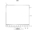
- FIG. 6 is a plan view showing an outline of the display device 1 in one aspect of the present invention.
- the display device 1 includes a light source group 2 including a plurality of light sources 2a, and a light guide plate for guiding light incident from the light source 2a and partially emitting the light from the light emission surface 41 (light guide And a light source control unit 3 for controlling the light emission state of the plurality of light sources 2a.
- a plurality of reflection patterns of the present embodiment are formed in a concave shape on the back surface of the light guide plate (light guide) 4 on the opposite side to the light emission surface 41.
- the light entering the light guide plate 4 from the light source 2 a propagates in the light guide plate 4 while totally reflecting in the light guide plate 4, and part of the light whose traveling direction is changed by the reflection pattern is the light emission surface 41 It is emitted from
- the light emission surface 41 it is possible to cause the light emission surface 41 to emit light and display, for example, a pattern corresponding to the arrangement of the reflection pattern by the light emitted with the traveling direction being changed by the plurality of reflection patterns.
- the display device 1 is not limited to a mode of displaying a two-dimensional (2D) image, and may be a display device capable of three-dimensional (3D) display.
- the configuration of the reflection pattern (optical structure) 10A of the present embodiment will be described based on FIGS. 1 and 2.
- the reflection pattern 10 ⁇ / b> A of the present embodiment is a hollow hollow structure provided on the back surface of the light guide plate 4.
- the reflection pattern 10A is regarded as a convex-shaped structure protruding inward from the back surface of the light guide plate 4.
- the structure when the reflection pattern 10A is viewed from the inside of the light guide plate 4 will be described.
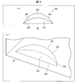
- FIG. 1A is a plan view showing the configuration of the reflection pattern 10A in the present embodiment
- FIG. 1B is a cross-sectional view taken along the line AA of FIG. c) is a perspective view showing the configuration of the reflection pattern 10A.
- the reflection pattern 10A is provided on the back surface side of the light guide plate 4, the light emission surface 41 side of the light guide plate 4 is upward, and the back surface side is downward.
- the outer edge curve 34 shown through the light guide plate 4 and shown as a relatively sparse dotted line is deeper than the reflecting surface 20 composed of the top outer edge 23 and the outer edge straight line 24 shown as a dense dotted line. Located on the side.
- the reflection pattern 10A in the present embodiment is a flat surface, which is a reflection surface (first surface) 20 that specularly reflects light, and a curve having a curved shape. And a curved surface (second surface) 30 including a surface 31 at both ends.
- the reflecting surface 20 and the curved surface 30 at both ends are adjacent to each other.
- the lower side of the reflection pattern 10A (the back side in the direction perpendicular to the paper surface of FIG. It is the formed opening.
- the reflecting surface 20 is a flat surface inclined at an acute inclination angle with respect to the reference surface 40, and reflects light incident on the light guide plate 4 toward the light emitting surface 41 of the light guide plate 4.
- the reflective surface 20 has a top outer edge (first outer edge) 23 whose outer edge is a ridgeline at the top of the reflection pattern 10A and a straight outer edge straight line (second outer edge straight line) 24 adjacent to the reference surface 40. It has become. Both ends of the top outer edge 23 are curved.
- the top outer edge 23 is composed of (i) an arc-shaped line rising in the direction in which the distance approaches each other from both ends of the outer edge straight line 24 and (ii) a line segment connecting the tips of these two arcs to each other .
- the double-end curved surface 30 is adjacent to the reflective surface 20 via the top outer edge 23.
- the curved surface 31 which the both-ends curved surface 30 contains is a surface which has a curved shape corresponding to the side of a cylinder.
- the curved surface 31 is formed, for example, as follows.
- a metal body is processed to produce a mold, and a mold is produced by electroforming using the produced mold.
- the light guide plate 4 in which the reflection pattern 10A is formed can be obtained.
- the reflection pattern 10A has substantially the same shape as a recess formed in a mold by processing a metal body.
- a surface of the cylindrical flat end mill corresponding to the reflecting surface 11 is formed on the mold, and (ii) rotation of the side face of the flat end mill
- surfaces corresponding to the curved surfaces 31 at both ends of the curved surfaces 30 are formed in the mold. That is, the curved surface 31 is a cylindrical surface corresponding to the cylindrical shape of the end mill.
- the curved surface 30 at both ends is a flat surface 32 between the curved surface 31 at one end and the curved surface 31 at the other end.
- the both-ends curved surface 30 is an outer-edge curve (the first surface is adjacent to the outer surface) whose outer edge is a straight line corresponding to (i) the top outer edge 23 and (ii) the curved surface 31 and the flat surface 32. There is no outer edge) 34).
- the outer edge curve 34 is a line segment included in the reference surface 40 and is a line segment having the same shape as the top outer edge 23.
- the reference surface 40 can also be expressed as a virtual plane including an outer edge straight line (an outer edge not adjacent to the second surface) 24 and an outer edge curve 34.
- Both ends of the reflection pattern 10A are referred to as an end e.
- the end e is a portion near the vertex v where the top outer edge 23, the outer edge straight line 24 and the outer edge curve 34 intersect.
- FIG. 2 is an enlarged view of the end e.
- the pattern depth is constant, for example, as in a triangular prism-type reflection pattern
- the reflection pattern behaves to emit discrete light, for example, as a Bessel function by diffraction. Therefore, there is a problem that the optical performance of the reflection pattern is deteriorated.
- the present inventors can reduce the influence of diffraction and improve the optical performance as compared to the prior art by setting the end e of the reflection pattern 10A as follows. I found out what I could do.
- the end e has an arc corresponding to the curved surface 31 of the both-end curved surface 30.
- the angle ⁇ is 90 degrees or less. Therefore, the length of the perpendicular (corresponding to the pattern depth) perpendicular to the outer edge straight line 24 in the reflecting surface 20 gradually becomes gradually due to the arc of the top outer edge 23 of the reflecting surface 20 and the curved shape of the curved surface 31 included in the both-end curved surface 30. Change.
- the degree of discreteness due to diffraction changes, light of different discrete degrees overlaps. As a result, the discreteness of the light emitted from the reflection pattern 10A can be relaxed.
- the reflection pattern 10A has the above-mentioned arc, it is possible to reduce the portion having a small depth as much as possible, as compared to the case where the depth is changed at a constant rate. Furthermore, as the pattern depth decreases, the amount of change in the pattern depth increases.
- the reflection pattern 10A in one aspect of the present invention also exhibits the following effects. That is, when the conventional triangular prism-shaped reflection pattern 130 as shown in FIG. 9B is formed by injection molding, molding sag may occur on the side surface of the reflection pattern 130. Such a shaped sag reflects (scatters) light incident from the side direction of the reflection pattern 130.
- light is made incident from the side direction of the reflection pattern 130 (the direction perpendicular to the paper surface in FIG. 9B)
- light is transmitted through the reflection pattern 130, that is, reflection in the reflection pattern 130. It is a case where light is intended not to exit from the surface 123.
- a trapezoidal prism-shaped reflection pattern 140 as shown in FIG. 9C can be considered as a shape that hardly causes the above-described molded sag.
- the projecting end portions 142 are present at both ends of the trapezoidal lower base 141, the occurrence of forming sag can be suppressed.
- the base angle of the trapezoid needs to be reduced to a certain extent in order to suppress the occurrence of molding sag.
- a portion where the distance between the bottom side 143 and the oblique side 144 is short increases.
- the influence of the above-mentioned diffraction becomes remarkable, and the directivity of the light emitted from the surface 123 is spread, so that the optical performance is deteriorated.
- the reflection pattern 10A in one aspect of the present invention has an arc corresponding to the curved surface 31 of the both-end curved surface 30 at the end e. Further, when the angle formed by the tangent at the vertex v of the curved surface 31 and the outer edge straight line 24 is ⁇ , the angle ⁇ is 90 degrees or less. Therefore, when the reflection pattern 10A is formed by injection molding, the resin flow can be made smooth by the arc of the top outer edge 23 of the reflection surface 20 and the curved shape of the curved surface 31 included in the both-end curved surface 30. it can. As a result, the occurrence of molding sag can be suppressed during the injection molding of the reflection pattern 10, and the generation of noise light can also be suppressed.
- the reflection pattern 10A formed in a concave shape on the back surface of the light guide plate formed by injection molding has been described.
- the optical structure in one aspect of the present invention is not necessarily limited to this.
- it may be a concave pattern formed by notching the back surface of the light guide plate.
- it may be a convex-shaped reflection pattern formed so as to protrude outward from the light guide plate.
- the optical structure in one aspect of the present invention is not limited to the configuration integrally provided with the light guide plate, and may be attached to the back surface of the light guide plate, for example.
- the optical structure in one aspect of the present invention may be made of a material that totally reflects light.
- the optical structure according to one aspect of the present invention is a recess-like pattern provided on the back surface of the light guide plate, and an exit structure that changes the path of the light by refracting the light incident on the light guide plate. It may be the body. In this case, refracted light is emitted from the back surface of the light guide plate.
- Modification 2 In the display device 1 according to the first embodiment, the traveling direction of the light incident on the light guide plate 4 is changed according to the arrangement and the direction of the reflection pattern 10A, and the light is emitted from the light emission surface 41 to the light emission surface 41. It was an apparatus for displaying a two-dimensional image or the like.
- the optical structure, the light guide including the optical structure, and the display device including the light guide according to one embodiment of the present invention are not limited to displaying a two-dimensional image or the like.
- the display device in one aspect of the present invention may spatially project a three-dimensional image (stereoscopic image). For example, a plurality of reflection patterns are arranged, and an image for the left eye and an image for the right eye are displayed on the light emission surface 41 side of the light guide plate 4 so that the observer can observe a surface image having a stereoscopic effect.
- the optical structure in one embodiment of the present invention can be applied to such a display device.
- the display device in one aspect of the present invention may have, for example, a configuration in which a plurality of optical structures reflect or refract incident image light.
- the reflected or refracted light is emitted from the light emission surface 41 and forms an image at an imaging point on a plane. This allows the user to visually recognize the image projected in the air when looking at the virtual plane.
- the optical structure in one aspect of the present invention can also be applied to such a display device.
- the display device in one aspect of the present invention may be a display device that displays a symbol, a picture, an image, and the like by using the directivity of light emitted from the light guide plate 4.
- the display device may use a light guide plate to switch the display of the pattern, or use a directivity to perform special appearance expression in which the light emission state of the pattern is not uniform. It may be used to perform binocular or multiview stereoscopic display. Also, as an imaging method in the case of using a light guide plate, a known method can be used.
- Second Embodiment Another embodiment of the present invention is described below with reference to FIGS. 3 and 4.
- the configuration other than that described in the present embodiment is the same as that of the first embodiment.
- members having the same functions as the members shown in the drawing of the first embodiment are given the same reference numerals, and the description thereof will be omitted.
- a concave-shaped pattern was formed on the back surface of a light guide plate using a flat end mill, and a mold for injection molding was sometimes manufactured.
- the rotation speed of the rotation center of the flat end mill is 0 and the rotation speed near the rotation center axis is relatively low, there is a problem that the surface to be cut becomes rough and does not become a mirror surface near the rotation center axis. .
- the present embodiment has been made in view of the above problems, and an object thereof is to provide an optical structure which can make the entire first surface a mirror surface and can further improve the optical performance. In providing the body.
- FIG. 3 (a) is a cross-sectional view showing a reflection pattern 10B of the present embodiment formed on the back surface of the light guide plate 4, and FIG. 3 (b) is from a direction perpendicular to the surface of the reflection surface 20. It is a figure for demonstrating the shape of the reflective pattern 10B seen.
- a reflection pattern 10 ⁇ / b> B is provided on the rear surface (reference surface 40) of the light guide plate 4.
- the light incident from the side surface of the light guide plate 4 is specularly reflected by the reflection surface 20 of the reflection pattern 10 B, and is emitted from the light emission surface 41 of the light guide plate 4.
- the maximum value of the distance between the boundary line (top outer edge 23) between the reflecting surface 20 and the plane 32 included in the both-end curved surface 30 and the reference surface 40 is D. Further, the angle between the reflective surface 20 and the reference surface 40 is assumed to be ⁇ . Further, the length of the slope of the reflective surface 20, that is, the maximum value of the distance between the top outer edge 23 and the outer edge straight line 24 on the reflective surface 20 is set to l.
- the curved surface 31 of the reflection pattern 10B is a surface having a curved shape corresponding to the side surface of the cylinder, the radius of the bottom surface 50 of this cylinder is R, and the point of the center of the bottom surface of the cylinder is P.
- the radius R and the point P are shown in FIG.
- a flat end mill can be used, and the tip end surface of the flat end mill corresponds to the bottom surface of the cylinder. It will be.
- the reflection pattern 10B of the present embodiment has the following formula (1) D ⁇ R sin ⁇ (1) Is true.
- the maximum value (distance l) of the perpendicular length from the point on the top outer edge (first outer edge) 23 to the outer edge straight line (second outer edge straight line) 24 ) Is shorter than the radius of the bottom of the cylinder. That is, the distance l is shorter than the radius R.
- the inclination (angle ⁇ ) of the tangent line 51 to the outer edge straight line 24 is less than 90 degrees.
- FIG. 4A is a front view of the tool 60 used to manufacture the reflection pattern 10B
- FIG. 4B is a side view of the tool 60
- FIG. 4C is a view of manufacturing the mold 70 using the tool 60. It is sectional drawing which shows.
- the reflection pattern 10B can be manufactured using a flat end mill, but here, a tool 60 with a diamond bar 61 attached to its tip is used.
- the diamond bar 61 is excellent in sharpness, and by using the diamond bar 61, the machined surface can be mirror-finished more precisely. As the tool 60 rotates about the rotation center axis 62, the diamond bar 61 pivots and cuts the object.
- the surface of the mold 70 is cut so as not to use the central portion (portion with low rotational speed) of the tool 60.
- the plane of the tip of the diamond bar 61 forms an inclined surface 71 corresponding to the reflection surface 20 of the reflection pattern 10B.
- the locus drawn by the diamond bar 61 when the tool 60 is rotated about the rotation center axis 62 has a cylindrical shape, and the surface connected by the side surface of the diamond bar 61 corresponds to the curved surface 30 at both ends of the reflection pattern 10B.
- An electroforming process can be performed using the produced casting mold 70 to produce a mold. Then, by injection molding using the mold, a light guide plate on which the reflection pattern 10B is formed can be obtained.
- the reflective pattern 10B of the present embodiment forms the reflective surface 20 or its mold, a region near the rotation center axis of the tool 60 is not used. Therefore, it is possible to make the entire reflection surface 20 of the reflection pattern 10B after cutting or the reflection pattern 10B obtained by injection molding using a mold a mirror surface. Therefore, optical performance can be further improved.
- the entire surface of the reflection pattern 10B of the present embodiment can be a mirror surface. There is no need to form a mirror surface later, and the cost can be reduced. Also, there is no need to use a special device.
- the curved surface 30 at both ends is composed of the curved surfaces 31 at both ends and the flat surface 32 between them.
- the curved shapes at both ends are different from each other.
- FIG. 5A is a plan view showing the configuration of the reflection pattern 10C in the present embodiment
- FIG. 5B is a perspective view showing the configuration of the reflection pattern 10C.
- the light guide plate 4 is shown passing through.
- the reflection surface 200 formed of a flat surface is a part of a circle.
- the reflection pattern 10C has an overall curved surface 300 having a curved shape adjacent to the reflective surface 200.
- the reflective surface 200 and the generally curved surface 300 are adjacent via the top outer edge 230.
- the outer edge of the reflective surface 200 comprises a top outer edge 230 and an outer edge straight line 240.
- the outer edge of the generally curved surface 300 comprises a top outer edge 230 and an outer edge curve 340.
- the top outer edge 230 and the outer edge curve 340 are shaped so as to eliminate the straight portions of the top outer edge 23 and the outer edge curve 34 in the first embodiment, respectively, and are smooth curves.
- Such a reflection pattern 10C can be manufactured by cutting without moving the tool 60 in the in-plane direction of the surface of the mold 70 in the manufacturing method as described in the second embodiment.
- Embodiment 4 Another embodiment of the present invention will be described below with reference to FIG.
- the configuration other than that described in the present embodiment is the same as the first embodiment and the second embodiment. Further, for convenience of explanation, members having the same functions as the members shown in the drawing of the first embodiment are given the same reference numerals, and the description thereof is omitted.
- the curved surface 31 at both ends has a curved shape with a constant curvature, corresponding to the side surface of the cylinder.
- the curved shape is different in that it is composed of two cylindrical surfaces.
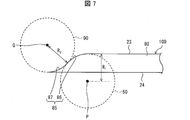
- FIG. 7 is a view for explaining the shape of the reflective pattern 10D in the present embodiment, as viewed from the direction perpendicular to the surface of the reflective surface 80. As shown in FIG.
- the reflection pattern 10D of the present embodiment is provided with a reflection surface 80 formed of a flat surface, and the curved shape of the curved surface at both ends of the reflection pattern 10D is as follows.
- the curved shape of the curved surface will be described here based on the shape of the top outer edge 23 when the reflective surface 80 is viewed from the direction along the perpendicular line of the reflective surface 80.
- the top outer edge 23 corresponding to the portion of the curved surface in the reflection pattern 10D is referred to as a curved outer edge 85.
- the curved surface in the reflection pattern 10D has a first curved surface and a second curved surface.
- the curved outer edge 85 includes a first curved outer edge 86 corresponding to the first curved surface and a second curved outer edge 87 corresponding to the second curved surface.
- the first curved surface is a curved surface corresponding to the side surface of the first cylinder
- the second curved surface is a curved surface corresponding to the side surface of the second cylinder.
- the center point P of the bottom surface 50 of the first cylinder, the radius and R 1, point a center of the second cylindrical bottom 90 Q, the radius is R 2.
- the point P and the point Q are located on opposite sides of the curved outer edge 85 which is a boundary between the reflective surface 80 and the curved surface in the reflective pattern 10D.
- the curved outer edge 85 can also be said to be a curve that forms a gentle S-shaped curve.
- the above radius R 1 and radius R 2 may be the same value, or may be different from each other.
- Such a reflection pattern 10D may be further processed, for example, on a mold obtained by electroforming after cutting of the mold 70 in the manufacturing method as described in the second embodiment. It can be manufactured by injection molding using a mold obtained by
- the optical structure according to one aspect of the present invention is an optical structure that emits light by changing the traveling direction of light, and includes a flat surface, and a first surface that changes the traveling direction of light And a second surface formed adjacent to the first surface and including a surface having a curved shape corresponding to the side surface of the cylinder.
- the reflection pattern behaves to emit discrete light by diffraction as in, for example, a Bessel function.
- the outer edge of the first surface of the optical structure includes an arc corresponding to the curved shape of the second surface. Therefore, the length (corresponding to the pattern depth) of the perpendicular perpendicular to the base of the first surface gradually changes corresponding to the arc. As a result, since the degree of discreteness due to diffraction changes, light of different discrete degrees overlaps. As a result, the discreteness of light emitted from the optical structure can be relaxed.
- a reflection pattern having a small pattern depth is susceptible to diffraction, and the degree of discreteness becomes extremely high. According to the above configuration, it is possible to reduce the portion where the depth is small as much as possible as compared to the case where the depth is changed at a constant rate. Furthermore, the shape can be made such that the amount of change in the pattern depth increases as the pattern depth decreases.
- the optical structure in one aspect of the present invention changes the path of the light by reflecting or refracting the incident light on the first surface.
- the light path of light can be changed with a simple configuration.
- the optical structure can be provided, for example, in a concave shape on the bottom surface of the light guide, and can be a reflection pattern that reflects the light incident on the light guide and emits it from the surface side, or refracts the incident light It is also possible to use a refraction pattern that emits from the bottom side.
- the optical structure can also be provided in a convex shape.
- the optical structure according to one aspect of the present invention further includes an outer edge not adjacent to the second surface among the outer edges of the first surface, and the first surface among the outer edges of the second surface
- a virtual plane including the non-adjacent outer edge is referred to as a reference plane, and the maximum value of the distance between the boundary line between the first plane and the second plane and the reference plane is D, and the first plane
- D the angle formed with the reference plane
- R the radius of the bottom of the cylinder
- R be the radius of the cross section when the cylinder is cut in a plane perpendicular to the long axis of the cylinder when it is regarded as.
- the radius of this cross section corresponds to the radius R of the base of the cylinder.
- the area near the central axis of rotation of the flat end mill is not used when forming the first surface or the mold thereof. Therefore, the entire first surface of the optical structure after cutting or the optical structure formed by injection molding using a mold can be made into a mirror surface. Therefore, optical performance can be further improved.
- an outer edge of the first surface not adjacent to the second surface among the outer edges of the first surface, and an outer edge of the outer edge of the second surface are the first surface
- An imaginary plane including a non-adjacent outer edge is referred to as a reference surface
- an outer edge of the first surface adjacent to the second surface is a first outer edge, and an outer edge adjacent to the reference surface.
- the maximum value of the length of the perpendicular from the point on the first outer edge to the second outer edge straight line is shorter than the radius of the bottom of the cylinder.
- the maximum value of the length of the perpendicular from the point on the first outer edge to the second outer edge straight line is shorter than the radius of the bottom surface of the cylinder. That is, when forming the first surface or its mold, the area near the central axis of rotation of the flat end mill is not used. Therefore, the entire first surface can be a mirror surface.
- an outer edge of the first surface not adjacent to the second surface among the outer edges of the first surface, and an outer edge of the outer edge of the second surface are the first surface
- An imaginary plane including a non-adjacent outer edge is referred to as a reference surface
- an outer edge of the first surface adjacent to the second surface is a first outer edge, and an outer edge adjacent to the reference surface.
- the inclination of the tangent of the curve indicated by the first outer edge is preferably less than 90 degrees with respect to the second outer edge straight line .
- the inclination of the tangent of the curve indicated by the first outer edge with respect to the second outer edge straight line is less than 90 degrees.
- the second surface may include the curved shape at both ends, and the two curved shapes may be adjacent to each other.
- the second surface includes the curved surface at both ends, and a flat surface is included between the curved surfaces.
- the curved shape is formed at both ends of the second surface, and each of the curved shapes corresponds to a side surface of the first cylinder as the cylinder.
- the center of and the center of the bottom of the second cylinder may be located on opposite sides of the boundary between the first surface and the second surface.
- a light guide comprising the above-mentioned optical structure, a display comprising the light guide and a light source for causing light to enter the light guide, and a display utilizing directivity of light emitted from the light guide
- the display device to perform is also contained in the technical scope of this invention.
Landscapes
- Physics & Mathematics (AREA)
- General Physics & Mathematics (AREA)
- Optics & Photonics (AREA)
- Engineering & Computer Science (AREA)
- Theoretical Computer Science (AREA)
- General Engineering & Computer Science (AREA)
- Planar Illumination Modules (AREA)
- Light Guides In General And Applications Therefor (AREA)
- Illuminated Signs And Luminous Advertising (AREA)
Abstract
回折の影響を低減し、光学性能を従来よりも向上させることができる光学構造体、導光体、および発光装置を提供する。反射パターン(10A)は、光の進行方向を変化させて出射させる光学構造体であって、平坦な面からなり、光の進行方向を変化させる反射面(20)と、反射面(20)に隣接して形成され、円柱の側面に対応する湾曲形状を有する面を含む両端湾曲面(30)とを備えている。
Description
本発明は、光の進行方向を変化させて出射させる光学構造体、該光学構造体を備えた導光体、および該導光体を備えた表示装置に関する。
従来、光源から出射された光を導光板の側面から入射させ、導光板の裏面側に設けられた反射パターンにより光を反射させて導光板の表面から出射させる技術が知られている。
例えば、特許文献1には、図8に示すように、導光板120の裏面124における所定の文字に対応する形状の領域に三角プリズム型の反射パターン130を配置し、光源100または光源110を交互に点灯させることによって、導光板120の表面123側に異なる文字を表示する技術が開示されている。
ここで、反射パターン130は、光に対してスリットの様な働きもし、光を回折させる。そのため、反射パターン130の反射面131により反射された光には、図9の(a)に示すように、回折による広がりが生じる。
図9の(b)は、反射パターン130を表面123側(図9の(a)における上側)から見た平面図である。反射面131の短手方向の長さLが短くなるほど、換言すれば反射パターン130のパターン深さが浅いほど、上記回折の影響が顕著になる。
長さLが一定な反射パターン130では、回折によって、角度方向に対して例えばベッセル関数の様に離散的な光を出射する振る舞いをする。その結果、反射パターン130の光学性能が悪化してしまう。本明細書において「反射パターンの光学性能」とは、導光板120の表面123側に表示される文字、図形、記号、立体画像、および投影画像等の表示品質に関する性能を意味し、換言すれば導光板120の光分け演出性および画質の良否に関する性能を意味する。
本発明は、上記の問題点に鑑みてなされたものであり、その目的は、回折の影響を低減し、光学性能を従来よりも向上させることができる光学構造体、導光体、および発光装置を提供することにある。
上記の課題を解決するために、本発明の一態様における光学構造体は、光の進行方向を変化させて出射させる光学構造体であって、平坦な面からなり、光の進行方向を変化させる第1面と、前記第1面に隣接して形成され、円柱の側面に対応する湾曲形状を有する面を含む第2面とを備えている。
本発明の一態様によれば、回折の影響を低減し、光学性能を従来よりも向上させることができる光学構造体、導光体、および発光装置を提供することができるという効果を奏する。
〔実施形態1〕
本発明の一実施形態について、図1、図2および図6に基づいて説明すれば、以下のとおりである。本実施の形態では、光の進行方向を変化させて出射させる光学構造体の一例としての、例えば、導光板の裏面に凹部状に形成された反射パターンについて説明する。このような導光板は、例えば、次のように製造することができる。すなわち、金属体を加工して鋳型を作製し、作製した鋳型を用いて電鋳する。電鋳により得られた金型を用いて射出成形することにより、上記導光板を形成することができる。
本発明の一実施形態について、図1、図2および図6に基づいて説明すれば、以下のとおりである。本実施の形態では、光の進行方向を変化させて出射させる光学構造体の一例としての、例えば、導光板の裏面に凹部状に形成された反射パターンについて説明する。このような導光板は、例えば、次のように製造することができる。すなわち、金属体を加工して鋳型を作製し、作製した鋳型を用いて電鋳する。電鋳により得られた金型を用いて射出成形することにより、上記導光板を形成することができる。
<表示装置1>
図6に基づいて、本発明の一態様における表示装置1について説明する。図6は、本発明の一態様における表示装置1の概要を示す平面図である。
図6に基づいて、本発明の一態様における表示装置1について説明する。図6は、本発明の一態様における表示装置1の概要を示す平面図である。
図6に示すように、表示装置1は、複数の光源2aを含む光源群2と、光源2aから入射した光を導光し、その一部を光出射面41から出射させる導光板(導光体)4と、複数の光源2aの発光状態を制御する光源制御部3と、を備えている。
導光板(導光体)4における光出射面41とは反対側の裏面に、本実施の形態の反射パターンが凹部状に複数形成されている。光源2aから導光板4内に入射した光は、導光板4内を全反射しながら導光板4内を伝播し、上記反射パターンによって進行方向が変化させられた一部の光が光出射面41から出射される。
これにより、複数の反射パターンによって進行方向が変化させられて出射された光によって、例えば反射パターンの配置に対応する図柄を光出射面41に発光表示させることができる。
なお、表示装置1は、2次元(2D)の画像を表示する態様に限定されず、3次元(3D)表示が可能な表示装置であってもよい。
<反射パターン10A>
図1および図2に基づいて、本実施の形態の反射パターン(光学構造体)10Aの構成について説明する。本実施の形態の反射パターン10Aは、導光板4の裏面に設けられた、凹部状の中空の構造である。ここで、本発明の理解を容易にするために、図1の(a)および図2の説明においては、反射パターン10Aを、導光板4の裏面から内側に突出した凸部状の構造とみなして説明する。換言すれば、導光板4の内部側から反射パターン10Aを見た場合の構造について説明する。
図1および図2に基づいて、本実施の形態の反射パターン(光学構造体)10Aの構成について説明する。本実施の形態の反射パターン10Aは、導光板4の裏面に設けられた、凹部状の中空の構造である。ここで、本発明の理解を容易にするために、図1の(a)および図2の説明においては、反射パターン10Aを、導光板4の裏面から内側に突出した凸部状の構造とみなして説明する。換言すれば、導光板4の内部側から反射パターン10Aを見た場合の構造について説明する。
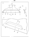
図1の(a)は本実施の形態における反射パターン10Aの構成を示す平面図であり、図1の(b)は(a)のA-A線矢視断面図であり、図1の(c)は反射パターン10Aの構成を示す斜視図である。ここで、上述のように、反射パターン10Aは導光板4の裏面側に設けられているとし、導光板4の光出射面41側を上方向とし、裏面側を下方向としている。図1の(c)においては、導光板4を透過して示し、比較的疎な点線として示す外縁曲線34は、密な点線として示す頂部外縁23および外縁直線24からなる反射面20よりも奥側に位置している。
図1の(a)~(c)に示すように、本実施の形態における反射パターン10Aは、平坦な面からなり光を正反射する反射面(第1面)20と、湾曲形状を有する湾曲面31を両端部に含む両端湾曲面(第2面)30とを有している。反射面20と両端湾曲面30とは互いに隣接している。
導光板4における、反射パターン10Aが形成されている裏面を基準面40とすると、反射パターン10Aの下側(図1の(a)における紙面に垂直な方向の奥側)は、基準面40に形成された開口部となっている。
反射面20は、基準面40に対して鋭角の傾斜角度にて傾斜した平坦な面であり、導光板4に入射した光を導光板4の光出射面41に向けて反射する。反射面20は、その外縁が、反射パターン10Aの頂部における稜線である頂部外縁(第1外縁)23と、基準面40に隣接している直線状の外縁直線(第2外縁直線)24とからなっている。この頂部外縁23の両端部は湾曲している。換言すれば、頂部外縁23は、(i)外縁直線24の両端からそれぞれ互いに距離が近づく方向に立ち上がる円弧状の線と、(ii)それら2つの円弧の先端同士を互いに結ぶ線分とからなる。
両端湾曲面30は、上記頂部外縁23を介して反射面20と隣接している。両端湾曲面30が含む湾曲面31は、円柱の側面に対応する湾曲形状を有する面である。ここで、この湾曲面31および上記円柱についての理解を容易にするために、反射パターン10Aの製造方法を概略的に説明する。湾曲面31は、例えば以下のようにして形成される。
すなわち、例えばフラットエンドミルを用いて、金属体を加工して鋳型を作製し、作製した鋳型を用いて電鋳することにより金型を作製する。作製した金型を用いて射出成形することにより、反射パターン10Aが形成された導光板4を得ることができる。反射パターン10Aは、金属体を加工して鋳型に形成した凹部と略同一の形状となる。
上記フラットエンドミルを所望の方向に動かして加工することにより、(i)円柱形状のフラットエンドミルの先端側が反射面11に対応する面を上記鋳型に形成し、(ii)フラットエンドミルの側面の回転に対応して、両端湾曲面30の両端部の湾曲面31に対応する面が上記鋳型に形成される。つまり、湾曲面31は、上記エンドミルの円柱形状に対応する円筒面となっている。
また、両端湾曲面30は、一端側の湾曲面31と他端側の湾曲面31との間は平面32となっている。両端湾曲面30は、その外縁が、(i)上記頂部外縁23と、(ii)湾曲面31に対応する曲線および平面32に対応する直線からなる外縁曲線(前記第1面とは隣接していない外縁)34とからなっている。外縁曲線34は、基準面40に含まれる線分であって、頂部外縁23と同様の形状の線分である。
また、基準面40は、外縁直線(前記第2面とは隣接していない外縁)24と外縁曲線34とを含む仮想平面であると表現することもできる。
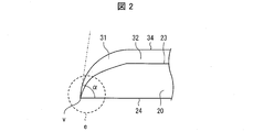
反射パターン10Aの両端部を端部eとする。端部eは、頂部外縁23と外縁直線24と外縁曲線34とが交わる頂点vの近傍部分である。
図2は、端部eを拡大して示す図である。ここで、上述のとおり、例えば三角プリズム型の反射パターンのようにパターン深さが一定の場合、反射パターンは、回折によって例えばベッセル関数の様に離散的な光を出射する振る舞いをする。よって、反射パターンの光学性能が悪化するという課題があった。
そこで、本発明者らは、図2に示すように、反射パターン10Aの端部eを以下のような構成とすることにより、回折の影響を低減し、光学性能を従来よりも向上させることができることを見出した。
すなわち、端部eでは、両端湾曲面30が有する湾曲面31に対応する円弧を有している。ここで、湾曲面31の頂点vにおける接線と、外縁直線24とが成す角の角度をαとすると、角度αは90度以下となっている。そのため、反射面20の頂部外縁23の円弧、および両端湾曲面30が含む湾曲面31の湾曲形状によって反射面20における外縁直線24に垂直な垂線の長さ(パターン深さに対応)が徐々に変化する。これにより、回折による離散度合が変化するため、異なる離散度合の光が重なり合う。その結果、反射パターン10Aから出射する光の離散性を緩和することができる。
ここで、一定の割合でパターン深さを変える方法も考えられるが、前述のように、パターン深さが小さい部分では、回折の影響を受け易く、極端に離散度合が大きくなる。これに対して、反射パターン10Aは、上記円弧を有していることにより、一定の割合で深さを変える場合よりも、深さが小さい部分をなるべく少なくすることができる。さらには、パターン深さが小さくなるに従って、パターン深さの変化量が大きくなる形状となっている。
したがって、回折の影響を低減し、光学性能を従来よりも向上させることができる。
また、本発明の一態様における反射パターン10Aは、以下のような効果も奏する。すなわち、図9の(b)に示すような従来の三角プリズム型の反射パターン130を射出成形で形成した場合、反射パターン130の側面に成形ダレが生じることがある。そのような成形ダレは、反射パターン130の側面方向から入射した光を反射(散乱)する。ここで、反射パターン130の側面方向(図9の(b)における紙面に垂直な方向)から光を入射させる場合とは、該反射パターン130を光が透過すること、すなわち該反射パターン130における反射光が表面123から出射しないことを意図している場合である。
成形ダレによって反射(散乱)した光の一部が表面123から漏出することにより、導光板120の表面123側に、意図しない発光(ノイズ光)が観察される。そのため、反射パターン130の光学性能が悪化し得る。
ここで、上述のような成形ダレが生じ難い形状として、図9の(c)に示すような、例えば台形プリズム型の反射パターン140が考えられる。このような台形プリズム型の反射パターン140では、台形の下底141の両端に突端部142があるため、成形ダレが生じることが抑制され得る。
しかしながら、反射パターン140を射出成形する場合に、成形ダレが生じることを抑制するためには、台形の底角をある程度小さくする必要がある。この場合、底辺143と斜辺144との距離が近い部分(回折の影響を受け易い部分)が多くなる。その結果、上述した回折の影響が顕著になり、表面123から出射される光の指向性が広がるため、光学性能が悪化してしまう。
これに対して、本発明の一態様における反射パターン10Aは、端部eにおいて、両端湾曲面30が有する湾曲面31に対応する円弧を有している。また、湾曲面31の頂点vにおける接線と、外縁直線24とが成す角の角度をαとすると、角度αは90度以下となっている。そのため、反射パターン10Aを射出成形にて形成する場合に、反射面20の頂部外縁23の円弧、および両端湾曲面30が含む湾曲面31の湾曲形状によって樹脂の流動を滑らかなものとすることができる。その結果、反射パターン10の射出成型時に成形ダレが生じることを抑制することができ、ノイズ光の発生を抑制することもできる。
したがって、成形ダレによるノイズ光の発生および回折の影響を低減し、光学性能を従来よりも向上させることができる。
(変形例1)
上記実施形態1では、本発明の一態様における光学構造体として、射出成形により形成された導光板の裏面に凹部状に形成された反射パターン10Aについて説明した。本発明の一態様における光学構造体としては、必ずしもこれに限らない。例えば、導光板の裏面を切り欠くことによって形成された凹部状のパターンであってもよい。また、導光板から外側に突出するように形成された凸形状の反射パターンであってもよい。また、本発明の一態様における光学構造体は、導光板と一体に設けられる構成に限られず、例えば導光板の裏面に取り付けられるものであってもよい。この場合、本発明の一態様における光学構造体は、光を全反射させる材料から成るものであってもよい。
上記実施形態1では、本発明の一態様における光学構造体として、射出成形により形成された導光板の裏面に凹部状に形成された反射パターン10Aについて説明した。本発明の一態様における光学構造体としては、必ずしもこれに限らない。例えば、導光板の裏面を切り欠くことによって形成された凹部状のパターンであってもよい。また、導光板から外側に突出するように形成された凸形状の反射パターンであってもよい。また、本発明の一態様における光学構造体は、導光板と一体に設けられる構成に限られず、例えば導光板の裏面に取り付けられるものであってもよい。この場合、本発明の一態様における光学構造体は、光を全反射させる材料から成るものであってもよい。
或いは、本発明の一態様における光学構造体は、導光板の裏面に設けられた凹部状のパターンであって、導光板に入射した光を屈折させることにより、当該光の経路を変更する出射構造体であってもよい。この場合、導光板の裏面から、屈折光が出射される。
(変形例2)
上記実施形態1における表示装置1は、導光板4に入射した光が、反射パターン10Aの配置および向きに応じて進行方向が変化させられて、光出射面41から出射して光出射面41に2次元の画像等を表示させる装置であった。ただし、本発明の一態様における光学構造体、該光学構造体を備えた導光体、および該導光体を備えた表示装置は、2次元の画像等を表示させることに限定されない。
上記実施形態1における表示装置1は、導光板4に入射した光が、反射パターン10Aの配置および向きに応じて進行方向が変化させられて、光出射面41から出射して光出射面41に2次元の画像等を表示させる装置であった。ただし、本発明の一態様における光学構造体、該光学構造体を備えた導光体、および該導光体を備えた表示装置は、2次元の画像等を表示させることに限定されない。
本発明の一態様における表示装置は、3次元映像(立体画像)を空間投影するものであってよい。例えば、複数の反射パターンが配列されて、導光板4の光出射面41側に左眼用画像と右眼用画像とが表示され、観察者が立体感のある面画像を観測することができるような表示装置に、本発明の一態様における光学構造体は適用することができる。
また、本発明の一態様における表示装置は、例えば、入射された画像光を複数の光学構造体が反射または屈折する構成であってもよい。反射または屈折された光は、光出射面41から出射され、平面上の結像点にて結像する。これにより、ユーザは、仮想の平面を見たときに、空中に投影された画像を視認することができる。本発明の一態様における光学構造体は、このような表示装置にも適用することができる。
また、本発明の一態様における表示装置は、導光板4から出射する光の指向性を利用して、図柄、絵、像等の表示を行う表示装置であってもよい。
具体的には、表示装置は、導光板を用いて、図柄の表示切替や、指向性を利用して図柄の発光状態が均一でない特殊な見栄え表現を行うものであってもよく、導光板を用いて、二眼式または多眼式の立体表示を行うものであってもよい。また、導光板を用いた場合の結像方式としては、公知の方式を使用することができる。
〔実施形態2〕
本発明の他の実施形態について、図3および図4に基づいて説明すれば、以下のとおりである。尚、本実施の形態において説明すること以外の構成は、前記実施形態1と同じである。また、説明の便宜上、前記実施形態1の図面に示した部材と同一の機能を有する部材については、同一の符号を付し、その説明を省略する。
本発明の他の実施形態について、図3および図4に基づいて説明すれば、以下のとおりである。尚、本実施の形態において説明すること以外の構成は、前記実施形態1と同じである。また、説明の便宜上、前記実施形態1の図面に示した部材と同一の機能を有する部材については、同一の符号を付し、その説明を省略する。
従来、フラットエンドミルを用いて例えば導光板の裏面に凹部状のパターンを形成すること、および射出成型用の金型を製造することがあった。ここで、フラットエンドミルの回転中心の回転速度は0であり、回転中心軸近傍の回転速度は比較的低いことから、回転中心軸近傍では切削対象の面が荒れて鏡面にならないという課題があった。
本実施の形態は、上記のような問題に鑑みてなされたものであって、その目的は、第1面の全体を鏡面にすることができ、光学性能をより一層向上させることができる光学構造体を提供することにある。
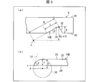
図3の(a)は導光板4の裏面に形成された本実施の形態の反射パターン10Bを示す断面図であり、図3の(b)は反射面20の表面に対して垂直な方向から見た、反射パターン10Bの形状を説明するための図である。
図3に示すように、導光板4の裏面(基準面40)に反射パターン10Bが設けられている。導光板4の側面から入射した光は、反射パターン10Bの反射面20にて正反射されて、導光板4の光出射面41から出射される。
反射面20と両端湾曲面30が含む平面32との境界線(頂部外縁23)と、基準面40との間の距離の最大値をDとする。また、反射面20と基準面40とがなす角度をθとする。また、反射面20の斜面の長さ、すなわち反射面20上にける頂部外縁23と外縁直線24との間の距離の最大値をlとする。
ここで、反射パターン10Bの湾曲面31は、円柱の側面に対応する湾曲形状を有する面であり、この円柱の底面50の半径をRとし、円柱の底面の中心の点をPとする。図3に、半径Rおよび点Pを示す。説明を簡単にするために、例えば、導光板4の裏面を切り欠いて反射パターン10Bを形成する場合、フラットエンドミルを用いることができ、該フラットエンドミルの先端面が、上記円柱の底面に相当することになる。
本実施の形態の反射パターン10Bは、下記式(1)
D<Rsinθ ・・・(1)
が成り立つ。
D<Rsinθ ・・・(1)
が成り立つ。
また、本実施の形態の反射パターン10Bは、他の側面では、頂部外縁(第1外縁)23上の点から外縁直線(第2外縁直線)24へ至る垂線の長さの最大値(距離l)は、前記円柱の底面の半径よりも短い。つまり、上記距離lは半径Rよりも短い。
また、本実施の形態の反射パターン10Bは、他の側面では、頂部外縁(第1外縁)23と外縁直線(第2外縁直線)24との交点である点vにおいて、頂部外縁23が示す曲線の接線51の、外縁直線24に対する傾き(角度β)は、90度未満である。
(反射パターン10Bの製造方法)
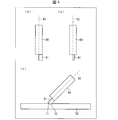
図4の(a)は反射パターン10Bの製造に用いられる工具60の正面図であり、(b)は工具60の側面図であり、(c)は工具60を用いて鋳型70を製造する様子を示す断面図である。
図4の(a)は反射パターン10Bの製造に用いられる工具60の正面図であり、(b)は工具60の側面図であり、(c)は工具60を用いて鋳型70を製造する様子を示す断面図である。
反射パターン10Bは、フラットエンドミルを用いて製造することができるが、ここでは、先端にダイヤモンドバー61が装着された工具60を用いる。ダイヤモンドバー61は切れ味が優れており、ダイヤモンドバー61を用いることにより、加工面をより精密に鏡面加工することができる。工具60が回転中心軸62を中心として回転することにより、ダイヤモンドバー61が旋回し、対象物を切削する。
図4の(c)に示すように、工具60の中心部(回転速度が低い部分)を使わないように、鋳型70の表面を切削加工する。ダイヤモンドバー61の先端の平面が、反射パターン10Bの反射面20に対応する傾斜面71を形成する。また、工具60が回転中心軸62を中心として回転したときのダイヤモンドバー61が描く軌跡は円柱形状となり、ダイヤモンドバー61の側面によって結索された面が、反射パターン10Bの両端湾曲面30に対応する面72を形成する。
作製した鋳型70を用いて、電鋳処理を行い、金型を作製することができる。そして、その金型を用いて射出成型することにより、反射パターン10Bが形成された導光板を得ることができる。
尚、工具60を用いて、鋳型70ではなく樹脂母材を切り欠いて、反射パターン10Bが形成された導光板を製造することもできる。
このように、本実施の形態の反射パターン10Bは、反射面20またはその鋳型を形成するときに、工具60の回転中心軸近傍の領域は使用されない。そのため、切削後の反射パターン10B、または鋳型を用いて射出成形して得られた反射パターン10Bの反射面20の全体を鏡面にすることができる。したがって、光学性能をより一層向上させることができる。
一般に、ミクロンサイズのパターンを研磨することは容易ではないし、非常に手間がかかる。また、研磨によって歪みが出たら、やり直しになってしまう。
本実施の形態の反射パターン10Bは、全面を鏡面とすることができる。後から鏡面を形成する必要がなく、コストを低減することができる。また、特別な装置を使う必要がない。
〔実施形態3〕
本発明の他の実施形態について、図5に基づいて説明すれば、以下のとおりである。尚、本実施の形態において説明すること以外の構成は、前記実施形態1および実施形態2と同じである。また、説明の便宜上、前記実施形態1の図面に示した部材と同一の機能を有する部材については、同一の符号を付し、その説明を省略する。
本発明の他の実施形態について、図5に基づいて説明すれば、以下のとおりである。尚、本実施の形態において説明すること以外の構成は、前記実施形態1および実施形態2と同じである。また、説明の便宜上、前記実施形態1の図面に示した部材と同一の機能を有する部材については、同一の符号を付し、その説明を省略する。
前記実施形態1における反射パターン10Aでは、両端湾曲面30は、両端部の湾曲面31と、それらの間の平面32とからなっていた。これに対して、本実施の形態の反射パターン10Cでは、両端部の湾曲形状が互いに隣接している点が異なっている。
図5の(a)は本実施の形態における反射パターン10Cの構成を示す平面図であり、図5の(b)は反射パターン10Cの構成を示す斜視図である。図5の(b)においては、導光板4を透過して示している。
図5に示すように、本実施の形態の反射パターン10Cは、平坦な面からなる反射面200が円の一部である。また、反射パターン10Cは、反射面200と隣接する、湾曲形状を有する全体湾曲面300を有している。反射面200と全体湾曲面300とは、頂部外縁230を介して隣接している。反射面200の外縁は、頂部外縁230と外縁直線240とからなっている。全体湾曲面300の外縁は、頂部外縁230と外縁曲線340とからなっている。頂部外縁230および外縁曲線340はそれぞれ、前記実施形態1における頂部外縁23および外縁曲線34の直線部分が無くなった形状であり、滑らかな曲線となっている。
このような反射パターン10Cは、前記実施形態2にて説明したような製造方法において、工具60を鋳型70の表面の面内方向に動かさずに切削加工を行うことによって、製造することができる。
これにより、反射面200が円の一部である反射パターン10Cを実現することができる。
〔実施形態4〕
本発明の他の実施形態について、図7に基づいて説明すれば、以下のとおりである。尚、本実施の形態において説明すること以外の構成は、前記実施形態1および実施形態2と同じである。また、説明の便宜上、前記実施形態1の図面に示した部材と同一の機能を有する部材については、同一の符号を付し、その説明を省略する。
本発明の他の実施形態について、図7に基づいて説明すれば、以下のとおりである。尚、本実施の形態において説明すること以外の構成は、前記実施形態1および実施形態2と同じである。また、説明の便宜上、前記実施形態1の図面に示した部材と同一の機能を有する部材については、同一の符号を付し、その説明を省略する。
前記実施形態1における反射パターン10Aでは、両端湾曲面30は、両端部の湾曲面31が、円柱の側面に対応する、曲率が一定の湾曲形状を有していた。これに対して、本実施の形態の反射パターン10Dでは、湾曲形状が、2つの円筒面からなっている点が異なっている。
図7は、本実施の形態における反射パターン10Dの形状を説明するための図であり、反射面80の表面に対して垂直な方向から見た図である。
図7に示すように、本実施の形態の反射パターン10Dは、平坦な面からなる反射面80を備え、反射パターン10Dの両端における湾曲面の湾曲形状が以下のようになっている。なお、説明の便宜上、ここでは、湾曲面の湾曲形状を、反射面80に立てた垂線に沿う方向から反射面80を見たときの、頂部外縁23の形状に基づいて説明する。
反射パターン10Dにおける湾曲面の部分に対応する頂部外縁23を、湾曲外縁85と称する。反射パターン10Dにおける湾曲面は、第1湾曲面および第2湾曲面を有している。湾曲外縁85は、上記第1湾曲面に対応する第1湾曲外縁86、および上記第2湾曲面に対応する第2湾曲外縁87からなっている。
上記第1湾曲面は、第1円柱の側面に対応する湾曲面であり、上記第2湾曲面は、第2円柱の側面に対応する湾曲面である。ここで、第1円柱の底面50の中心を点P、半径をR1とし、第2円柱の底面90の中心を点Q、半径をR2とする。
点Pと点Qとは、反射パターン10Dにおける反射面80と、湾曲面との境界線である湾曲外縁85の互いに反対側に位置している。湾曲外縁85は、緩やかなS字状のカーブを描く曲線であるということもできる。
上記半径R1と半径R2とは、互いに同一の値であってもよく、互いに異なる値であってもよい。
このような反射パターン10Dは、例えば、前記実施形態2にて説明したような製造方法において、鋳型70の切削加工を行った後に電鋳して得られた金型に対して、さらに加工することによって得られる金型を用いて、射出成形することにより製造することができる。
これにより、反射面である第1面の両端部が波型の形状の湾曲面を有する光学構造体を実現できる。
以上のように、本発明の一態様における光学構造体は、光の進行方向を変化させて出射させる光学構造体であって、平坦な面からなり、光の進行方向を変化させる第1面と、前記第1面に隣接して形成され、円柱の側面に対応する湾曲形状を有する面を含む第2面とを備えている。
ここで、例えば三角プリズム型の反射パターンのようにパターン深さが一定の場合、反射パターンは、回折によって例えばベッセル関数の様に離散的な光を出射する振る舞いをする。
上記の構成によれば、光学構造体の第1面の外縁には、第2面の湾曲形状に対応する円弧が含まれている。そのため、該円弧に対応して、第1面における底辺に垂直な垂線の長さ(パターン深さに対応)が徐々に変化する。これにより、回折による離散度合が変化するため、異なる離散度合の光が重なり合う。その結果、光学構造体から出射する光の離散性を緩和することができる。
また、パターン深さが小さい反射パターンは、回折の影響を受け易く、極端に離散度合が大きくなる。上記の構成によれば、一定の割合で深さを変える場合よりも、深さが小さい部分をなるべく少なくすることができる。さらには、パターン深さが小さくなるに従って、パターン深さの変化量が大きくなる形状とすることができる。
したがって、回折の影響を低減し、光学性能を従来よりも向上させることができる。
また、本発明の一態様における光学構造体は、前記第1面において、入射した光を反射または屈折させることにより、当該光の経路を変更する。
上記の構成によれば、簡単な構成で光の光路を変更することができる。光学構造体は、例えば導光体の底面に凹部状に設けられ、導光体に入射した光を反射して表面側から出射する反射パターンとすることができ、または、入射した光を屈折して底面側から出射する屈折パターンとすることもできる。また、光学構造体は、凸形状に設けることもできる。
本発明の一態様における光学構造体は、さらに、前記第1面の外縁のうち、前記第2面とは隣接していない外縁と、前記第2面の外縁のうち、前記第1面とは隣接していない外縁とを含む仮想平面を基準面と称し、前記第1面と前記第2面との境界線と前記基準面との間の距離の最大値をDとし、前記第1面と前記基準面とがなす角度をθとし、前記円柱の底面の半径をRとした場合、下記式(1)
D<Rsinθ ・・・(1)
が成り立つことが好ましい。
D<Rsinθ ・・・(1)
が成り立つことが好ましい。
ここで、例えばフラットエンドミルを使用して、導光体の表面に光学構造体を形成する場合、または鋳型となる物体の表面に光学構造体に対応する凹部を形成する場合に、フラットエンドミルを円柱と見なした場合の、当該円柱の長軸に対して垂直な平面で当該円柱を切断したときの断面の半径をRとする。この断面の半径は、前記円柱の底面の半径Rに対応する。
フラットエンドミルの回転中心軸近傍の回転速度は比較的低いため、回転中心軸近傍では鏡面を形成することが困難である。
上記の構成によれば、前記第1面またはその鋳型を形成するときに、フラットエンドミルの回転中心軸近傍の領域は使用されない。そのため、切削後の光学構造体、または鋳型を用いて射出成形した光学構造体の第1面の全体を鏡面にすることができる。したがって、光学性能をより一層向上させることができる。
また、本発明の一態様における光学構造体は、前記第1面の外縁のうち、前記第2面とは隣接していない外縁と、前記第2面の外縁のうち、前記第1面とは隣接していない外縁とを含む仮想平面を基準面と称し、前記第1面の外縁のうち、前記第2面と隣接している外縁を第1外縁とし、前記基準面と隣接している外縁を第2外縁直線とし、前記第1外縁上の点から前記第2外縁直線へ至る垂線の長さの最大値は、前記円柱の底面の半径よりも短いことが好ましい。
上記の構成によれば、前記第1外縁上の点から前記第2外縁直線へ至る垂線の長さの最大値は、前記円柱の底面の半径よりも短い。つまり、第1面またはその鋳型を形成するときに、フラットエンドミルの回転中心軸近傍の領域は使用されない。そのため、第1面の全体を鏡面にすることができる。
また、本発明の一態様における光学構造体は、前記第1面の外縁のうち、前記第2面とは隣接していない外縁と、前記第2面の外縁のうち、前記第1面とは隣接していない外縁とを含む仮想平面を基準面と称し、前記第1面の外縁のうち、前記第2面と隣接している外縁を第1外縁とし、前記基準面と隣接している外縁を第2外縁直線とし、前記第1外縁と前記第2外縁直線との交点において、前記第1外縁が示す曲線の接線の、前記第2外縁直線に対する傾きは、90度未満であることが好ましい。
上記の構成によれば、前記第1外縁と前記第2外縁直線との交点において、前記第1外縁が示す曲線の接線の、前記第2外縁直線に対する傾きは、90度未満である。この構成は、第1面またはその鋳型を形成するときに、フラットエンドミルの回転中心軸近傍の領域を使用しないことにより実現される。そのため、第1面の全体を鏡面にすることができる。
また、本発明の一態様における光学構造体は、前記第2面は、両端に前記湾曲形状を含み、2つの前記湾曲形状は、互いに隣接しているとすることができる。
上記の構成によれば、反射面である第1面が円の一部である光学構造体を実現できる。
また、本発明の一態様における光学構造体は、前記第2面は、両端に前記湾曲形状の面を含み、前記湾曲形状の面の間には平面が含まれている。
上記の構成によれば、反射面である第1面が横長の光学構造体を実現できる。
また、本発明の一態様における光学構造体は、前記第2面の両端に前記湾曲形状が形成されており、前記湾曲形状のそれぞれは、前記円柱としての第1円柱の側面に対応する第1湾曲面および前記円柱としての第2円柱の側面に対応する第2湾曲面を有し、前記第1面に立てた垂線に沿う方向から前記第1面を見たとき、前記第1円柱の底面の中心と前記第2円柱の底面の中心とは、前記第1面と前記第2面との境界線の互いに反対側に位置していてもよい。
上記の構成によれば、反射面である第1面の両端部が波型の形状の湾曲面を有する光学構造体を実現できる。
上述の光学構造体を備える導光体、前記導光体と当該導光体に光を入射する光源とを備える表示装置、および、前記導光体から出射する光の指向性を利用した表示を行う表示装置も本発明の技術的範囲に含まれる。
本発明は上述した各実施形態に限定されるものではなく、請求項に示した範囲で種々の変更が可能であり、異なる実施形態にそれぞれ開示された技術的手段を適宜組み合わせて得られる実施形態についても本発明の技術的範囲に含まれる。
1 表示装置
2a 光源
4 導光板(導光体)
10A、10B 反射パターン(光学構造体)
20 反射面(第1面)
23 頂部外縁(第1外縁)
24 外縁直線(第2外縁直線)
30 両端湾曲面(第2面)
31 湾曲面(湾曲形状の面)
32 平面
40 基準面
41 光出射面
200 反射面(第1面)
300 全体湾曲面(第2面)
2a 光源
4 導光板(導光体)
10A、10B 反射パターン(光学構造体)
20 反射面(第1面)
23 頂部外縁(第1外縁)
24 外縁直線(第2外縁直線)
30 両端湾曲面(第2面)
31 湾曲面(湾曲形状の面)
32 平面
40 基準面
41 光出射面
200 反射面(第1面)
300 全体湾曲面(第2面)
Claims (11)
- 光の進行方向を変化させて出射させる光学構造体であって、
平坦な面からなり、光の進行方向を変化させる第1面と、
前記第1面に隣接して形成され、円柱の側面に対応する湾曲形状を有する面を含む第2面とを備える光学構造体。 - 前記第1面において、入射した光を反射または屈折させることにより、当該光の経路を変更する請求項1に記載の光学構造体。
- 前記第1面の外縁のうち、前記第2面とは隣接していない外縁と、前記第2面の外縁のうち、前記第1面とは隣接していない外縁とを含む仮想平面を基準面と称し、
前記第1面と前記第2面との境界線と前記基準面との間の距離の最大値をDとし、前記第1面と前記基準面とがなす角度をθとし、前記円柱の底面の半径をRとした場合、下記式(1)
D<Rsinθ ・・・(1)
が成り立つ請求項1または2に記載の光学構造体。 - 前記第1面の外縁のうち、前記第2面とは隣接していない外縁と、前記第2面の外縁のうち、前記第1面とは隣接していない外縁とを含む仮想平面を基準面と称し、
前記第1面の外縁のうち、前記第2面と隣接している外縁を第1外縁とし、前記基準面と隣接している外縁を第2外縁直線とし、
前記第1外縁上の点から前記第2外縁直線へ至る垂線の長さの最大値は、前記円柱の底面の半径よりも短い請求項1から3のいずれか1項に記載の光学構造体。 - 前記第1面の外縁のうち、前記第2面とは隣接していない外縁と、前記第2面の外縁のうち、前記第1面とは隣接していない外縁とを含む仮想平面を基準面と称し、
前記第1面の外縁のうち、前記第2面と隣接している外縁を第1外縁とし、前記基準面と隣接している外縁を第2外縁直線とし、
前記第1外縁と前記第2外縁直線との交点において、前記第1外縁が示す曲線の接線の、前記第2外縁直線に対する傾きは、90度未満である請求項1から4のいずれか1項に記載の光学構造体。 - 前記第2面は、両端に前記湾曲形状を含み、2つの前記湾曲形状は、互いに隣接している請求項1から5のいずれか1項に記載の光学構造体。
- 前記第2面は、両端に前記湾曲形状の面を含み、前記湾曲形状の面の間には平面が含まれている請求項1から5のいずれか1項に記載の光学構造体。
- 前記第2面の両端に前記湾曲形状が形成されており、
前記湾曲形状のそれぞれは、前記円柱としての第1円柱の側面に対応する第1湾曲面および前記円柱としての第2円柱の側面に対応する第2湾曲面を有し、
前記第1面に立てた垂線に沿う方向から前記第1面を見たとき、前記第1円柱の底面の中心と前記第2円柱の底面の中心とは、前記第1面と前記第2面との境界線の互いに反対側に位置している請求項1または2に記載の光学構造体。 - 入射した光を導光し、その一部を光出射面から出射させる導光体であって、
請求項1から8のいずれか1項に記載の光学構造体を複数備える導光体。 - 請求項9に記載の導光体と、
前記導光体に光を入射する光源とを備える表示装置。 - 前記導光体から出射する光の指向性を利用した表示を行う請求項10に記載の表示装置。
Priority Applications (3)
| Application Number | Priority Date | Filing Date | Title |
|---|---|---|---|
| US16/461,700 US10670795B2 (en) | 2017-03-14 | 2017-11-24 | Optical structure, light guide, and a display device |
| CN201780071287.9A CN109964076B (zh) | 2017-03-14 | 2017-11-24 | 光学构造体、导光体及显示装置 |
| DE112017007240.9T DE112017007240B4 (de) | 2017-03-14 | 2017-11-24 | Optische anordnung, lichtleiter und anzeigevorrichtung |
Applications Claiming Priority (2)
| Application Number | Priority Date | Filing Date | Title |
|---|---|---|---|
| JP2017049220A JP6693452B2 (ja) | 2017-03-14 | 2017-03-14 | 光学構造体、導光体、および表示装置 |
| JP2017-049220 | 2017-03-14 |
Publications (1)
| Publication Number | Publication Date |
|---|---|
| WO2018168093A1 true WO2018168093A1 (ja) | 2018-09-20 |
Family
ID=63522952
Family Applications (1)
| Application Number | Title | Priority Date | Filing Date |
|---|---|---|---|
| PCT/JP2017/042255 Ceased WO2018168093A1 (ja) | 2017-03-14 | 2017-11-24 | 光学構造体、導光体、および表示装置 |
Country Status (5)
| Country | Link |
|---|---|
| US (1) | US10670795B2 (ja) |
| JP (1) | JP6693452B2 (ja) |
| CN (1) | CN109964076B (ja) |
| DE (1) | DE112017007240B4 (ja) |
| WO (1) | WO2018168093A1 (ja) |
Families Citing this family (2)
| Publication number | Priority date | Publication date | Assignee | Title |
|---|---|---|---|---|
| US10883670B1 (en) * | 2019-08-22 | 2021-01-05 | Champ Vision Display Inc. | Light guide module and light source module |
| TWM639487U (zh) | 2022-12-16 | 2023-04-01 | 誠屏科技股份有限公司 | 燈飾模組 |
Citations (6)
| Publication number | Priority date | Publication date | Assignee | Title |
|---|---|---|---|---|
| US20050057915A1 (en) * | 2003-02-12 | 2005-03-17 | Hon Hai Precision Industry Co., Ltd. | Patterned light guide plate and display device having same |
| JP2007206335A (ja) * | 2006-02-01 | 2007-08-16 | Harison Toshiba Lighting Corp | 液晶表示装置用バックライト |
| JP2008084544A (ja) * | 2006-09-25 | 2008-04-10 | Harison Toshiba Lighting Corp | 導光板、照明装置及び液晶表示装置用バックライト |
| JP2008203633A (ja) * | 2007-02-21 | 2008-09-04 | Harison Toshiba Lighting Corp | 表示装置 |
| JP2015156317A (ja) * | 2014-02-20 | 2015-08-27 | オムロン株式会社 | 反射構造体、導光体、発光装置および遊技機 |
| JP2016122162A (ja) * | 2014-12-25 | 2016-07-07 | オムロン株式会社 | 導光板、表示装置及び遊技機 |
Family Cites Families (7)
| Publication number | Priority date | Publication date | Assignee | Title |
|---|---|---|---|---|
| US7364341B2 (en) * | 1999-02-23 | 2008-04-29 | Solid State Opto Limited | Light redirecting films including non-interlockable optical elements |
| DE60030541T2 (de) | 2000-01-06 | 2007-08-30 | Koninklijke Philips Electronics N.V. | Leuchte und leuchttafeln |
| JP4279815B2 (ja) * | 2005-08-30 | 2009-06-17 | 日本ライツ株式会社 | 導光板および平面照明装置 |
| US8740443B2 (en) * | 2006-07-03 | 2014-06-03 | Core Wireless Licensing S.A.R.L. | Changing graphics in an apparatus including user interface illumination |
| JP5512380B2 (ja) * | 2010-04-30 | 2014-06-04 | 株式会社フジクラ | 表示装置 |
| JP5701434B1 (ja) * | 2014-07-11 | 2015-04-15 | 株式会社フジクラ | 表示装置および表示方法 |
| JP6369353B2 (ja) * | 2015-02-24 | 2018-08-08 | オムロン株式会社 | 導光体および発光装置 |
-
2017
- 2017-03-14 JP JP2017049220A patent/JP6693452B2/ja active Active
- 2017-11-24 DE DE112017007240.9T patent/DE112017007240B4/de active Active
- 2017-11-24 CN CN201780071287.9A patent/CN109964076B/zh active Active
- 2017-11-24 US US16/461,700 patent/US10670795B2/en active Active
- 2017-11-24 WO PCT/JP2017/042255 patent/WO2018168093A1/ja not_active Ceased
Patent Citations (6)
| Publication number | Priority date | Publication date | Assignee | Title |
|---|---|---|---|---|
| US20050057915A1 (en) * | 2003-02-12 | 2005-03-17 | Hon Hai Precision Industry Co., Ltd. | Patterned light guide plate and display device having same |
| JP2007206335A (ja) * | 2006-02-01 | 2007-08-16 | Harison Toshiba Lighting Corp | 液晶表示装置用バックライト |
| JP2008084544A (ja) * | 2006-09-25 | 2008-04-10 | Harison Toshiba Lighting Corp | 導光板、照明装置及び液晶表示装置用バックライト |
| JP2008203633A (ja) * | 2007-02-21 | 2008-09-04 | Harison Toshiba Lighting Corp | 表示装置 |
| JP2015156317A (ja) * | 2014-02-20 | 2015-08-27 | オムロン株式会社 | 反射構造体、導光体、発光装置および遊技機 |
| JP2016122162A (ja) * | 2014-12-25 | 2016-07-07 | オムロン株式会社 | 導光板、表示装置及び遊技機 |
Also Published As
| Publication number | Publication date |
|---|---|
| DE112017007240B4 (de) | 2022-02-17 |
| US20190353837A1 (en) | 2019-11-21 |
| JP2018152302A (ja) | 2018-09-27 |
| CN109964076B (zh) | 2021-04-06 |
| JP6693452B2 (ja) | 2020-05-13 |
| DE112017007240T5 (de) | 2019-12-12 |
| CN109964076A (zh) | 2019-07-02 |
| US10670795B2 (en) | 2020-06-02 |
Similar Documents
| Publication | Publication Date | Title |
|---|---|---|
| JP5701434B1 (ja) | 表示装置および表示方法 | |
| JP7095043B2 (ja) | 多様なファセット角を有するフレネルレンズアセンブリ | |
| TWI378278B (en) | Method of making an optical substrate having cavities | |
| CN104864362B (zh) | 反射构造体、导光体、发光装置及游戏机 | |
| US11982827B2 (en) | Diffraction light guide plate and display device including the same | |
| US10895759B2 (en) | Optical device and method of three-dimensional display | |
| KR102570053B1 (ko) | 도광판, 백라이트 모듈 및 디스플레이 장치 | |
| CN102326112A (zh) | 包括多功能镜片的显示装置,制造方法以及具有菲涅耳结构的光学元件 | |
| US20130128620A1 (en) | Vehicular lamp | |
| JP6798372B2 (ja) | 導光体、表示装置及び遊技機 | |
| JP6350177B2 (ja) | 発光装置 | |
| CN106796019B (zh) | 线照明显示装置以及导光体 | |
| CN107076986B (zh) | 成像光学器件和数据眼镜 | |
| WO2016006525A1 (ja) | 表示装置及び表示方法 | |
| JP2014240960A (ja) | 空間映像投映装置 | |
| JP2021089866A (ja) | 灯体 | |
| JP2016180776A (ja) | 表示装置および表示方法 | |
| CN109964076B (zh) | 光学构造体、导光体及显示装置 | |
| US10168535B2 (en) | Optical element and display device | |
| JP2010061028A (ja) | 光学シート、面光源装置および透過型表示装置 | |
| US11806606B2 (en) | Light guide plate, light emitting device, display device and game machine | |
| JP2024524390A (ja) | 導光体及びこれを用いた表示画面 | |
| JP2016122627A (ja) | 面光源装置および表示装置 | |
| JP2015222629A (ja) | 装飾照明装置 | |
| CN110608412A (zh) | 一种车辆用灯具花纹及其设计生成方法、车辆用灯具 |
Legal Events
| Date | Code | Title | Description |
|---|---|---|---|
| 121 | Ep: the epo has been informed by wipo that ep was designated in this application |
Ref document number: 17901115 Country of ref document: EP Kind code of ref document: A1 |
|
| 122 | Ep: pct application non-entry in european phase |
Ref document number: 17901115 Country of ref document: EP Kind code of ref document: A1 |