WO2018163508A1 - 列車制御システム、列車制御方法および列車の車上装置 - Google Patents
列車制御システム、列車制御方法および列車の車上装置 Download PDFInfo
- Publication number
- WO2018163508A1 WO2018163508A1 PCT/JP2017/040345 JP2017040345W WO2018163508A1 WO 2018163508 A1 WO2018163508 A1 WO 2018163508A1 JP 2017040345 W JP2017040345 W JP 2017040345W WO 2018163508 A1 WO2018163508 A1 WO 2018163508A1
- Authority
- WO
- WIPO (PCT)
- Prior art keywords
- train
- speed
- travel
- target
- target speed
- Prior art date
- Legal status (The legal status is an assumption and is not a legal conclusion. Google has not performed a legal analysis and makes no representation as to the accuracy of the status listed.)
- Ceased
Links
Images


Classifications
-
- B—PERFORMING OPERATIONS; TRANSPORTING
- B60—VEHICLES IN GENERAL
- B60L—PROPULSION OF ELECTRICALLY-PROPELLED VEHICLES; SUPPLYING ELECTRIC POWER FOR AUXILIARY EQUIPMENT OF ELECTRICALLY-PROPELLED VEHICLES; ELECTRODYNAMIC BRAKE SYSTEMS FOR VEHICLES IN GENERAL; MAGNETIC SUSPENSION OR LEVITATION FOR VEHICLES; MONITORING OPERATING VARIABLES OF ELECTRICALLY-PROPELLED VEHICLES; ELECTRIC SAFETY DEVICES FOR ELECTRICALLY-PROPELLED VEHICLES
- B60L15/00—Methods, circuits, or devices for controlling the traction-motor speed of electrically-propelled vehicles
- B60L15/40—Adaptation of control equipment on vehicle for remote actuation from a stationary place
-
- B—PERFORMING OPERATIONS; TRANSPORTING
- B61—RAILWAYS
- B61L—GUIDING RAILWAY TRAFFIC; ENSURING THE SAFETY OF RAILWAY TRAFFIC
- B61L27/00—Central railway traffic control systems; Trackside control; Communication systems specially adapted therefor
Definitions
- the present invention relates to a train control system, a train control method, and a train onboard device for suppressing a delay spread generated for a subsequent train traveling behind the preceding train due to a delay of the preceding train.
- a train control method for suppressing a delay spread generated for a subsequent train traveling behind the preceding train due to a delay of the preceding train.
- Patent Literature 1 discloses an on-vehicle cooperation system in which a ground device and on-vehicle devices on all trains in an area managed by the ground device are connected by a network.
- the ground device obtains the train travel information from the on-board device on each train, creates target information for the corresponding subsequent train by the internal processing device, and uses this target information on the vehicle on each train.
- the on-board device travels according to the sent target information.
- Patent Document 1 since the method described in Patent Document 1 performs processing based on the time information when the train arrives, a delay occurs in the departure time due to an increase in boarding time due to congestion or a boarding ride, etc. It is impossible to cope with the departure time delay depending on the dynamics. Under such circumstances, the succeeding train will excessively approach the preceding train, and the succeeding train will be braked by the signal and will stop in the middle of the station. In addition, the subsequent trains will be approached excessively in the same manner, so that the trains will stop in the middle of the station.
- the departure delay of the preceding train affects the subsequent train that runs behind it, and further spreads to the following train.
- energy consumption increases as compared to normal operation, and a train delay is spread.
- the train control system includes a shortest release time calculation unit provided on the ground side, a target speed calculation unit provided on the vehicle upper side or the ground side of the train, and a travel control device provided on the vehicle upper side.
- the shortest release time calculation unit has the brake pattern based on the departure time of the preceding train at the target station from the brake pattern for stopping the train before the occupied section by the preceding train traveling in front of the train.
- the target speed calculation unit obtains a station entry limit position for preventing the train from entering the target station from the brake pattern.
- the train's target speed is calculated from the train station entry limit position, current position, deceleration and shortest release time.
- the train is provided with a driving determination unit that determines a driving command for controlling the driving of the train based on the degree and the brake pattern, or a driving support unit that provides driving support information of the own train to the driver of the train. Is controlled by a travel control device.
- the present invention it is possible to minimize and avoid a stop between stations of a train, and it is possible to prevent an increase in energy consumption and prevent an increase or spread of a train delay as compared with normal operation. It becomes possible.
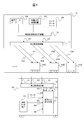
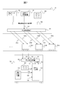
- FIG. 1 is a diagram illustrating an example of a system configuration and a data flow according to the first embodiment of the present invention.
- FIG. 2 is a diagram illustrating a flowchart of processing executed by the shortest release time calculation apparatus.
- FIG. 3 is a diagram illustrating an example of an internal configuration of the automatic train travel device.
- FIG. 4 is a diagram illustrating a flowchart of processing executed by the target speed calculation device.
- FIG. 5 is a diagram illustrating an example of an internal configuration of the travel determination device.
- FIG. 6 is a diagram showing an effect when the train control according to the present invention is performed.
- FIG. 7 is a diagram illustrating an example of a system configuration and data flow according to the second embodiment of the present invention.
- FIG. 1 is a diagram illustrating an example of a system configuration and a data flow according to the first embodiment of the present invention.
- FIG. 2 is a diagram illustrating a flowchart of processing executed by the shortest release time calculation apparatus.
- FIG. 3 is
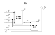
- FIG. 8 is a diagram illustrating an example of an internal configuration of the train traveling device.
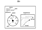
- FIG. 9 is a diagram illustrating a configuration example of a driving support screen displayed by the driving support device.
- FIG. 10 is a diagram illustrating an example of a system configuration and a data flow according to the third embodiment of the present invention.
- FIG. 1 is a diagram illustrating an example of a system configuration and a data flow according to the first embodiment of the present invention.
- the ground device 101 manages the information of the route under the jurisdiction, and transmits information to the trains 102A, 102B, 102C,... (Hereinafter collectively referred to as “train 102”) traveling on the route under the jurisdiction. .
- the train 102 (102A, 102B, 102C,%) Controls its own train based on the transmitted information.
- the ground device 101 includes an arrival / departure situation management device 103 that manages the arrival / departure situation of trains that travel on the route under jurisdiction, a time interval database 104 that manages time interval data (data indicating the time interval of train arrival),
- the shortest release time calculation device 106 is a station to which each train 102A, 102B, 102C,... Enters, based on the input information from the arrival / departure situation management device 103, the time interval database 104, and the diagram database 105.
- Brake pattern shortest release times 151A, 151B, 151C,... (Hereinafter collectively referred to as “shortest release time 151”) and station entry limit positions 152A, 152B, 152C for each train (Hereinafter collectively referred to as “station entry limit position 152”) is calculated.
- the shortest release time indicates the earliest time that the brake pattern disappears when the brake pattern disappears.
- the ground-side transmitting device 107 uses the train 102 (102A, 102B, 102C,%) For each information of the shortest release time 151 (151A, 151B, 151C, etc. And the station entry limit position 152 (152A, 152B, 152C,. Send to.
- the train 102 (see the lower diagram in FIG. 1) measures the upper vehicle receiving device 108 that receives information from the ground device 101, the database 109 that records the acceleration / deceleration characteristics of the train, the current train speed 154, and the current train position 155.
- a speed measuring device 110 that performs the operation and a train traveling device 111 that determines a train traveling method.
- the vehicle upper side receiving device 108 receives the shortest release time 151 and the station entry limit position 152 from the ground device 101, and also has a relationship with a preceding train that travels in front of the own train from a signal device (not shown).
- the fixed train approach limit position 153 is received.
- the speed measuring device 110 measures the current train position 155 obtained by integrating the current train speed 154 and the current train speed 154.
- a speed generator, GPS, or the like may be used as the speed measuring device 110.
- the automatic train traveling device 111 is based on the shortest release time 151, the station entry limit position 152, the own train entry limit position 153, the current train speed 154, the current train position 155, and the acceleration / deceleration characteristics 156 recorded in the database 109. Determine how the train will travel.
- the train 102 performs automatic operation according to the travel method determined by the automatic train travel device 111.
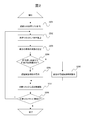
- FIG. 2 is a diagram showing a flowchart of processing executed by the shortest release time calculation device 106.
- the processing content will be described with reference to this flowchart.
- the shortest release time calculation device 106 is simply referred to as “calculation device 106”.
- step 201 the computing device 106 extracts a list of trains existing on the route under the jurisdiction, and proceeds to step 202.
- the diamond database 105 is taken into consideration, and an appropriate correction according to the arrival / departure situation is added by the arrival / departure situation management apparatus 101.
- step 202 the computing device 106 extracts one train existing between the stations from the train list extracted in step 201, and proceeds to step 203.
- step 203 the calculation device 106 calculates the number N of trains that have stopped before the own train until the station where the train extracted in step 202 is heading (to the station where the extracted train is heading). (Including trains that are stopped), the process proceeds to step 204. For this calculation, the diamond database 105 and the arrival / departure situation management apparatus 101 are used.
- step 204 the computing device 106 checks whether or not other trains stopped at the station where the train extracted in step 202 is heading are delayed. If another train stops and is delayed (Y), the process proceeds to step 205. On the other hand, if the other train is not stopped, or if the other train is stopped but the departure is not delayed (N), the process proceeds to step 206.
- step 205 the calculation device 106 calculates the shortest release time by the following calculation formula based on the number N of trains extracted in step 203, and proceeds to step 207.
- step 206 when the shortest release time has been issued even once until the computer 106 arrives at the station where the extracted train is heading, the calculation device 106 sets the shortest release time most recently issued among them. Command and go to step 207. If it has never been issued, the shortest release time is not specified.
- step 207 the computing device 106 deletes the current train from the list of trains existing on the line under its control, and proceeds to step 208.
- step 208 the computing device 106 checks whether there is still a train in the list of trains that exist on the route under its jurisdiction, and if it exists (Y), returns to step 202 and does not exist (N). If so, the process ends.
- FIG. 3 is a diagram illustrating an example of an internal configuration of the automatic train travel device 111 mounted on the on-board device 102.
- the automatic train travel device 111 includes a target speed calculation device 301 that calculates a target speed 351, a travel pattern database 302 that stores a target travel pattern 352, and a travel determination device 303 that determines a travel command 353.
- the target speed calculation device 301 calculates the target speed 351 of the own train based on the shortest release time 151, the station entry limit position 152, the current train position 155, and the acceleration / deceleration characteristics 156.
- the travel pattern database 302 stores a target travel pattern 352 of the own train configured by a set of (position, speed). At that time, the travel pattern database 302 stores at least one of a travel pattern created in advance and a travel pattern created during travel.
- the travel determination device 303 travels based on the own train approach limit position 153, the current train speed 154, the current train position 155, the acceleration / deceleration characteristics 156, the target speed 351, and the target travel pattern 352 of the own train. Command 353 is determined.
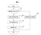
- FIG. 4 is a diagram illustrating a flowchart of processing executed by the target speed calculation device 301 provided in the automatic train travel device 111. The processing contents will be described below along this flowchart. In the following steps, the target speed calculation device 301 is simply referred to as “calculation device 301”.
- step 401 the calculation device 301 checks whether or not there is the shortest release time 151 (T_Release). If there is (Y), the calculation apparatus 301 proceeds to step 402, and if there is not (N), step 405 is performed. Proceed to
- step 402 the calculation device 301 acquires the station entry limit position 152 (X_LMA), and proceeds to step 403.
- step 403 the calculation device 301 acquires the train deceleration ( ⁇ [m / s / s]) based on the acceleration / deceleration characteristics 156, and proceeds to step 404.
- step 405 the calculation device 301 sets the maximum speed of the train to the target speed 351 and ends the process.
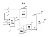
- FIG. 5 is a diagram illustrating an example of an internal configuration of a travel determination device 303 provided in the automatic train travel device 111.
- the travel determination device 303 includes a travel follow-up control unit 501 that determines a first travel command 551, a signal speed calculation unit 502 that calculates a signal speed 552, a target speed control unit 504 that determines a second travel command 554, and a comparison process. It consists of parts 503 and 505.
- the travel follow-up control unit 501 is configured to make the current train speed 154 and the current train position 155 closer to the target travel pattern 352 based on the current train speed 154, the current train position 155, and the target travel pattern 352. 1 running command 551 is determined.
- the signal speed calculation unit 502 calculates a signal speed 552 corresponding to the brake pattern speed of the own train at the current train position based on the own train approach limit position 153, the current train position 155, and the acceleration / deceleration characteristics 156.
- the comparison processing unit 503 outputs the smaller value of the signal speed 552 and the target speed 351 as the follow target speed 553.
- the target speed control unit 504 determines the second travel command 554 so that the current train speed 154 approaches the tracking target speed 553.
- the comparison processing unit 505 outputs the smaller command value of the first travel command 551 and the second travel command 554 as the travel command 353 of the own train.
- a known method may be used as a determination method of the first travel command 551 from the travel follow-up control unit 501 and a determination method of the second travel command 554 from the target speed control function 504, for example, the target speed Proportional control based on the deviation of the current speed may be used.
- the signal speed calculation unit 502 calculates the signal speed 552 as follows: the signal speed 552 is V_ATP [km / h], the own train entry limit position 153 is Y_LMA [m], and the current train position 155 is X [m].
- V_ATP (2 ⁇ ⁇ ⁇
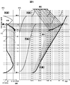
- FIG. 6 is a diagram showing an effect when the train control according to the present invention is performed. It is assumed that the train 1 stops at the station B at the time T0, the train 2 travels from the station A toward the station B, and the train 3 travels thereafter. After this, the effect obtained when the control according to the present invention is applied when the train 1 is delayed at the station B will be described.
- the diagram on the left side shows a travel locus when the control according to the present invention is applied to the train 3 with the horizontal axis representing speed and the vertical axis representing position. (Speed change).
- the diagram on the right side shows the position of each of train 1, train 2 and train 3 from time to time, with the horizontal axis representing time and the vertical axis representing position.
- step 201 ⁇ 202 ⁇ 203 ⁇ 204 (N) ⁇ 206 ⁇ 207 ⁇
- Train 2 (running pattern not shown) has arrived from the time-position locus shown in the right diagram of FIG. 6 to the vicinity of the approach limit position of the station heading at time T0. However, at time T0, there is no conflict with the brake pattern generated from the approach limit position of the station, and there is no departure delay in the preceding train 1, so the vehicle travels to stop at station B. The train 3 following the train 2 accelerates toward the target speed.
- step 401 (Y) ⁇ 402 ⁇ 403 ⁇ 404, and the respective target speeds VO21 and VO31 are calculated. Is done.
- the train 2 and the train 3 perform the control mode shown in FIG. 5 according to the target speeds VO21 and VO31.
- the train 3 is controlled according to the target speed VO31 because there is a distance to the brake limit PT1 determined by the approach limit P1 of the own train determined by the approach limit of the station that is heading and the preceding train 2. Become. Since the target speed VO31 is higher than the current speed, the train 3 is in an accelerated state (the left figure in FIG. 6).
- the target speed VO31 of the train 3 is in a direction approaching the current speed, but is higher than the current speed. Further, since there is a distance to the brake pattern PT2 determined by the approach limit P2 of the own train determined by the preceding train 2, control is performed according to the target speed VO31. For this reason, the train 3 continues to accelerate (left figure in FIG. 6).
- step 401 (Y) ⁇ 402 ⁇ 403 ⁇ 404
- the target speed VO32 is calculated. Further, since there is a distance to the brake pattern PT2 determined by the approach limit P2 of the own train determined by the preceding train 2, control is performed according to the target speed VO32. Since the target speed VO32 coincides with the current speed V2, the train 3 operates so as to maintain the current speed V2.
- the process proceeds from step 401 (Y) ⁇ 402 ⁇ 403 ⁇ 404, and the target speed VO33 is calculated. Further, since there is a distance to the brake pattern PT2 determined by the approach limit P2 of the own train determined by the preceding train 2, control is performed according to the target speed VO33. Since the target speed VO33 is lower than the current speed V3, the train 3 decelerates to become the target speed VO33 (the left diagram in FIG. 6).
- Time T3 to T4 As the time advances from time T3 to T4, the target speed VO33 of the train 3 is calculated to be a value that is lower than the current speed. Further, since there is still a distance to the brake pattern PT2 determined by the approach limit P2 of the own train determined by the preceding train 2, control is performed according to the target speed VO33. That is, the train 3 decelerates to reach the target speed VO33 (the left diagram in FIG. 6).
- Time T4 At time T4, the train 1 stopped at the station B departs.
- the shortest release time calculation device 106 shown in FIG. 2 for train 2 and train 3 both proceed in the order of step 201 ⁇ 202 ⁇ 203 ⁇ 204 (Y) ⁇ 205 ⁇ 207 ⁇ 208, and the shortest release of each.
- Times TO24 and TO34 are calculated.
- both the train 2 and the train 3 proceed in steps 401 (Y) ⁇ 402 ⁇ 403 ⁇ 404 to calculate the target speeds VO24 and VO34.
- the train 2 and the train 3 perform traveling control.
- the target speed VO24 for the train 2 is still 0, the train 2 remains stopped.
- control is performed according to the target speed VO34. It will be.
- the current speed of the train 3 is V4, but since the target speed VO34 is lower than the current speed V4, the train 3 decelerates to the target speed VO34 (the left figure in FIG. 6).
- Time T5 is the time when the train 1 has left the station B.
- the shortest release time calculation device 106 shown in FIG. 2 for train 2 and train 3 both proceed in the order of step 201 ⁇ 202 ⁇ 203 ⁇ 204 (Y) ⁇ 206 ⁇ 207 ⁇ 208, and the shortest release for each.
- TO24 and TO34 that have been output most recently are calculated.
- both the train 2 and the train 3 proceed in steps 401 (Y) ⁇ 402 ⁇ 403 ⁇ 404, and the TO24 and TO34 of the shortest opening time and the respective Since the station entry limit position has not changed, the target speeds VO24 and VO34 are calculated. According to the target speeds VO24 and VO34, the train 2 and the train 3 perform traveling control. However, since the target speed VO24 for the train 2 is still 0, the train 2 remains stopped.
- Time T6 is a time when the prevention of entering the station by the train 1 is canceled.
- the shortest release time calculation device 106 shown in FIG. 2 for train 2 and train 3 both proceed in the order of step 201 ⁇ 202 ⁇ 203 ⁇ 204 (Y) ⁇ 206 ⁇ 207 ⁇ 208, and the shortest release for each.
- TO24 and TO34 that have been output most recently are calculated.
- both the train 2 and the train 3 proceed in steps 401 (Y) ⁇ 402 ⁇ 403 ⁇ 404, and the shortest opening time for the train 2 is TO24.
- the target speed VO26 exceeding 0 is calculated, and the train 2 starts re-acceleration and heads for the station B.
- the target speed remains VO34.
- step 401 (Y) ⁇ 402 ⁇ 403 ⁇ 404.
- the process proceeds from step 401 (Y) ⁇ 402 ⁇ 403 ⁇ 404.
- the shortest opening time is TO24, since the station entry limit position has changed to station B, the target speed VO27 exceeding 0 is calculated, and the vehicle is approaching station B. Control.
- the shortest opening time is TO34, and the approach limit does not change, so the target speed remains VO34.
- Time T7 is the time when the train 2 departs.
- the process proceeds from step 201 ⁇ 202 ⁇ 203 ⁇ 204 (Y) ⁇ 206 ⁇ 207 ⁇ 208, and the shortest release time was output most recently.
- TO34 is calculated.
- the process proceeds from the train 401 to Step 401 (Y) ⁇ 402 ⁇ 403 ⁇ 404, the shortest opening time is TO34, and the approach limit does not change. The speed remains unchanged at VO34.
- Time T8 Time T ⁇ b> 8 is the time when the prevention of entering the station by the train 2 that precedes the train 3 is canceled.
- the process proceeds from step 201 ⁇ 202 ⁇ 203 ⁇ 204 (Y) ⁇ 206 ⁇ 207 ⁇ 208.
- the most recently output TO 34 is calculated.
- the process proceeds from step 401 (Y) ⁇ 402 ⁇ 403 ⁇ 404, and the shortest opening time is TO34.
- a target speed VO38 exceeding the target speed VO34 is calculated.
- the train 3 starts re-acceleration and heads for the station B.
- the train 3 has just reached the station entry limit position and can travel without applying unnecessary braking.
- the train 3 operates toward the station B according to a speed pattern as shown in the left diagram of FIG.
- FIG. 7 is a diagram illustrating an example of a system configuration and a data flow according to the second embodiment of the present invention.
- the train 102 and the automatic train travel device 111 shown in FIG. 1 are replaced with a train 701 and a train travel device 702, respectively.
- the components having the same numbers as those in FIG. 1 have the same contents as those in the first embodiment, and hence the description thereof is omitted below.
- the train 701 shown in the lower diagram of FIG. 7 includes an upper-side receiving device 108, a database 109 that records the acceleration / deceleration characteristics of the train, a measuring device 110 relating to the current train speed and speed position, and a train traveling device 702 that determines a traveling method. Composed.
- the vehicle upper side receiving device 108 receives the shortest release time 151 and the station entry limit position 152 from the ground device 101 and is determined by the relationship with the train traveling in front of the own train from the signal device (not shown).
- the own train approach limit position 153 is received.
- the speed measuring device 110 measures the current train position 155 obtained by integrating the current train speed 154 and the current train speed 154.
- the train travel device 702 determines a travel method based on the shortest release time 151, the station entry limit position 152, the own train entry limit position 153, the current train speed 154, the current train position 155, and the acceleration / deceleration characteristics 156. .
- FIG. 8 is a diagram illustrating an example of the configuration of the train traveling device 702.
- the train travel device 702 has a configuration in which the travel pattern database 302 is removed from the automatic train travel device 111 of the first embodiment shown in FIG. 3 and the travel determination device 303 is replaced with a drive support device 801. There is no change in the calculation device 301).
- the driving support device 801 determines driving support information based on the shortest release time 151, the own train approach limit position 153, the current train speed 154, the current train position 155, and the target speed 351.
- the driving support device 801 may have a display unit.
- FIG. 9 is a diagram illustrating a configuration example of a driving support screen displayed by the driving support device 801.
- the current time, the shortest release time 151, the remaining time that is the difference between the shortest release time 151 and the current time are displayed in the upper left part of the screen, and a speedometer is displayed in the left part of the screen.
- the target speed 351 and the current train speed 154 are displayed in the account.
- the operation history information and the operation target information are displayed with the time on the horizontal axis and the position on the vertical axis. Regarding these pieces of information, driving history information can be generated by combining the current train position 155 and the current time, and driving target information can be generated by combining the shortest release time 151 and the own train entry limit position 153. Is possible.
- FIG. 10 is a diagram illustrating an example of a system configuration and a data flow according to the third embodiment of the present invention.
- the ground device 1001 has the function of the target speed calculation device 301 of the automatic train traveling device 111 of the train 102 of the first embodiment on the ground device 1001 side of the third embodiment.
- the train database 1003, the train position management apparatus 1004, and the target speed calculation apparatus 1005 are provided.
- the third embodiment also uses trains 1002A, 1002B, 1002C,... (Hereinafter collectively referred to as the trains 1001A, 1002C,... Information is transmitted to “train 1002”), and the train 1002 (1002A, 1002B, 1002C,...) Controls itself based on the transmitted information.
- the train database 1003 records and stores acceleration / deceleration characteristics relating to trains traveling on the jurisdiction.
- the train position management device 1004 manages in real time the train position 1051 related to the train traveling on the line under its jurisdiction.
- the target speed calculation device 1005 is based on the shortest release time 151, the station entry limit position 152, information from the diagram database 105, the train acceleration / deceleration characteristics recorded in the train database 1003, and the train position 1051 from the train position management device 1004. Then, the target speeds 1052A, 1052B, 1052C,... Of the train 1002 (1002A, 1002B, 1002C,%) (Hereinafter collectively referred to as “target speed 1052”) are calculated. A target speed 1052 (1052A, 1052B, 1052C,%) From the target speed calculation apparatus 1005 is transmitted from the ground side transmission apparatus 1006 to the train 1002 (1002A, 1002B, 1002C,).
- the train 1002 shown in the lower part of FIG. 10 does not have the target speed calculation device 301 of the first embodiment as described above.
- the vehicle upper side receiving device 108 receives the target speed 1052 from the ground device 1001 and receives the own train approach limit position 153 determined by the relationship with the train traveling in front of the own train from a signal device (not shown). To do.
- the traveling pattern database 302 that stores the target traveling pattern 352 of the own train that is configured is the same as in the first embodiment.
- the traveling determination device 1007 determines a traveling method based on the target traveling pattern 352, the target speed 1052, the own train approach limit position 153, the current train speed 154, the current train position 155, and the acceleration / deceleration characteristics 156.
- the train 1002 is operated by automatic operation according to the travel method determined by the travel determination device 1007.
- the target speed calculation function 1005 provided in the ground device 1001 is the same as the processing flow of the target speed calculation device 301 shown in FIG. 4, and the current position 155 (X [m]) of the train used in step 404 is determined. What is necessary is just to change to the train position 1051 from the train position management apparatus 1004.
- the internal configuration of the travel determination device 1007 included in the train 1002 changes the target speed 351 of the travel determination device 303 shown in FIG. 5 to the target speed 1052 received from the ground device 1001.
- the driving support device 801 according to the second embodiment may be substituted for the automatic train traveling device 1007.
- Example 3 train control as shown in FIG. 6 can be performed. As a result, also in Example 3, the same effects as those of Example 1 and Example 2 described above can be obtained.
- 101 Ground device, 102, 102A, 102B, 102C: Train, 103: Arrival / departure status management device, 104: Time interval database, 105: Diamond database, 106: Shortest release time calculation device, 107: ground side transmission device, 108: vehicle upper side reception device, 109: Database for recording the acceleration / deceleration characteristics of trains, 110: Speed measuring device, 111: Train traveling device, 151: Shortest release time, 152: Station entry limit position, 153: Own train entry limit position, 154: Current train speed, 155: Current train position, 156: Acceleration / deceleration characteristics, 301: target speed calculation device, 302: travel pattern database, 303: Travel determination device, 351: Target speed, 352: Target running pattern of own train, 353: Running command of own train, 501: Travel tracking control unit, 502: Signal speed calculation unit, 503, 505: comparison processing unit, 504: target speed control unit, 551: First traveling command, 552: Signal speed, 553: follows
Landscapes
- Engineering & Computer Science (AREA)
- Mechanical Engineering (AREA)
- Power Engineering (AREA)
- Transportation (AREA)
- Electric Propulsion And Braking For Vehicles (AREA)
- Train Traffic Observation, Control, And Security (AREA)
Applications Claiming Priority (2)
| Application Number | Priority Date | Filing Date | Title |
|---|---|---|---|
| JP2017-042396 | 2017-03-07 | ||
| JP2017042396A JP6802091B2 (ja) | 2017-03-07 | 2017-03-07 | 列車制御システム、列車制御方法および列車の車上装置 |
Publications (1)
| Publication Number | Publication Date |
|---|---|
| WO2018163508A1 true WO2018163508A1 (ja) | 2018-09-13 |
Family
ID=63448435
Family Applications (1)
| Application Number | Title | Priority Date | Filing Date |
|---|---|---|---|
| PCT/JP2017/040345 Ceased WO2018163508A1 (ja) | 2017-03-07 | 2017-11-09 | 列車制御システム、列車制御方法および列車の車上装置 |
Country Status (2)
| Country | Link |
|---|---|
| JP (1) | JP6802091B2 (enExample) |
| WO (1) | WO2018163508A1 (enExample) |
Families Citing this family (2)
| Publication number | Priority date | Publication date | Assignee | Title |
|---|---|---|---|---|
| JP7413177B2 (ja) * | 2020-07-21 | 2024-01-15 | 株式会社東芝 | 運転曲線作成装置、運転支援装置および運転制御装置 |
| JP7781699B2 (ja) * | 2022-04-11 | 2025-12-08 | 株式会社日立製作所 | 列車制御システム |
Citations (4)
| Publication number | Priority date | Publication date | Assignee | Title |
|---|---|---|---|---|
| JPH05193502A (ja) * | 1991-10-25 | 1993-08-03 | Toshiba Corp | 最適走行パターン算出装置および算出システム |
| JPH0740835A (ja) * | 1993-07-30 | 1995-02-10 | Nippon Signal Co Ltd:The | ディジタル伝送式自動列車制御装置 |
| WO2015118671A1 (ja) * | 2014-02-07 | 2015-08-13 | 三菱電機株式会社 | 列車走行管理装置 |
| JP2017030674A (ja) * | 2015-08-05 | 2017-02-09 | 株式会社東芝 | 列車制御システム |
-
2017
- 2017-03-07 JP JP2017042396A patent/JP6802091B2/ja active Active
- 2017-11-09 WO PCT/JP2017/040345 patent/WO2018163508A1/ja not_active Ceased
Patent Citations (4)
| Publication number | Priority date | Publication date | Assignee | Title |
|---|---|---|---|---|
| JPH05193502A (ja) * | 1991-10-25 | 1993-08-03 | Toshiba Corp | 最適走行パターン算出装置および算出システム |
| JPH0740835A (ja) * | 1993-07-30 | 1995-02-10 | Nippon Signal Co Ltd:The | ディジタル伝送式自動列車制御装置 |
| WO2015118671A1 (ja) * | 2014-02-07 | 2015-08-13 | 三菱電機株式会社 | 列車走行管理装置 |
| JP2017030674A (ja) * | 2015-08-05 | 2017-02-09 | 株式会社東芝 | 列車制御システム |
Also Published As
| Publication number | Publication date |
|---|---|
| JP6802091B2 (ja) | 2020-12-16 |
| JP2018144676A (ja) | 2018-09-20 |
Similar Documents
| Publication | Publication Date | Title |
|---|---|---|
| CN104379396B (zh) | 列车控制装置 | |
| WO2015030068A1 (ja) | 運行管理システム、運行管理方法およびプログラム | |
| JP2018135018A (ja) | 運行制御システム | |
| JP6072314B2 (ja) | 列車走行管理装置 | |
| US10150491B2 (en) | Device and method for controlling train | |
| JP6619985B2 (ja) | 自動列車運転装置および列車運転支援装置 | |
| KR100283828B1 (ko) | 열차 운행관리 시스템 | |
| JP5972781B2 (ja) | 時隔曲線図作成装置 | |
| WO2018163508A1 (ja) | 列車制御システム、列車制御方法および列車の車上装置 | |
| US20170210405A1 (en) | Train control device | |
| JP2019089449A (ja) | 列車走行制御装置、方法及びプログラム | |
| KR20150137902A (ko) | 속도 제어 장치, 중앙 관리 서버, 및 이를 이용한 차량 속도 제어 시스템과 방법 | |
| JP2006006030A (ja) | 運転パターン作成装置、車両速度制御装置および車両運転支援装置。 | |
| CN110626391A (zh) | 一种乘客信息系统的信息预测方法 | |
| EP3192717A1 (en) | Operation control system | |
| JP7376413B2 (ja) | 自律走行車両の運行管理装置及び運行管理方法 | |
| JPH06321115A (ja) | 列車制御装置 | |
| JP2017204197A (ja) | 運転支援方法及び運転支援システム | |
| WO2018008337A1 (ja) | 走行パターン作成装置及び走行パターン作成方法 | |
| JP7466494B2 (ja) | 列車制御システム及び列車制御装置 | |
| WO2019135310A1 (ja) | 運転支援システム | |
| JP6613073B2 (ja) | 列車制御システム | |
| JP7045287B2 (ja) | 列車制御システムおよび列車制御方法 | |
| JP7781699B2 (ja) | 列車制御システム | |
| JP2005280542A (ja) | Atc/o装置 |
Legal Events
| Date | Code | Title | Description |
|---|---|---|---|
| 121 | Ep: the epo has been informed by wipo that ep was designated in this application |
Ref document number: 17900000 Country of ref document: EP Kind code of ref document: A1 |
|
| NENP | Non-entry into the national phase |
Ref country code: DE |
|
| 122 | Ep: pct application non-entry in european phase |
Ref document number: 17900000 Country of ref document: EP Kind code of ref document: A1 |