WO2018159341A1 - ロボットの制御方法 - Google Patents
ロボットの制御方法 Download PDFInfo
- Publication number
- WO2018159341A1 WO2018159341A1 PCT/JP2018/005643 JP2018005643W WO2018159341A1 WO 2018159341 A1 WO2018159341 A1 WO 2018159341A1 JP 2018005643 W JP2018005643 W JP 2018005643W WO 2018159341 A1 WO2018159341 A1 WO 2018159341A1
- Authority
- WO
- WIPO (PCT)
- Prior art keywords
- motor
- value
- current
- command
- overload detection
- Prior art date
Links
Images


Classifications
-
- B—PERFORMING OPERATIONS; TRANSPORTING
- B25—HAND TOOLS; PORTABLE POWER-DRIVEN TOOLS; MANIPULATORS
- B25J—MANIPULATORS; CHAMBERS PROVIDED WITH MANIPULATION DEVICES
- B25J9/00—Programme-controlled manipulators
- B25J9/16—Programme controls
- B25J9/1628—Programme controls characterised by the control loop
- B25J9/1641—Programme controls characterised by the control loop compensation for backlash, friction, compliance, elasticity in the joints
-
- B—PERFORMING OPERATIONS; TRANSPORTING
- B25—HAND TOOLS; PORTABLE POWER-DRIVEN TOOLS; MANIPULATORS
- B25J—MANIPULATORS; CHAMBERS PROVIDED WITH MANIPULATION DEVICES
- B25J9/00—Programme-controlled manipulators
- B25J9/16—Programme controls
- B25J9/1674—Programme controls characterised by safety, monitoring, diagnostic
-
- B—PERFORMING OPERATIONS; TRANSPORTING
- B25—HAND TOOLS; PORTABLE POWER-DRIVEN TOOLS; MANIPULATORS
- B25J—MANIPULATORS; CHAMBERS PROVIDED WITH MANIPULATION DEVICES
- B25J9/00—Programme-controlled manipulators
- B25J9/16—Programme controls
- B25J9/1694—Programme controls characterised by use of sensors other than normal servo-feedback from position, speed or acceleration sensors, perception control, multi-sensor controlled systems, sensor fusion
-
- H—ELECTRICITY
- H02—GENERATION; CONVERSION OR DISTRIBUTION OF ELECTRIC POWER
- H02P—CONTROL OR REGULATION OF ELECTRIC MOTORS, ELECTRIC GENERATORS OR DYNAMO-ELECTRIC CONVERTERS; CONTROLLING TRANSFORMERS, REACTORS OR CHOKE COILS
- H02P21/00—Arrangements or methods for the control of electric machines by vector control, e.g. by control of field orientation
- H02P21/0085—Arrangements or methods for the control of electric machines by vector control, e.g. by control of field orientation specially adapted for high speeds, e.g. above nominal speed
- H02P21/0089—Arrangements or methods for the control of electric machines by vector control, e.g. by control of field orientation specially adapted for high speeds, e.g. above nominal speed using field weakening
-
- H—ELECTRICITY
- H02—GENERATION; CONVERSION OR DISTRIBUTION OF ELECTRIC POWER
- H02P—CONTROL OR REGULATION OF ELECTRIC MOTORS, ELECTRIC GENERATORS OR DYNAMO-ELECTRIC CONVERTERS; CONTROLLING TRANSFORMERS, REACTORS OR CHOKE COILS
- H02P21/00—Arrangements or methods for the control of electric machines by vector control, e.g. by control of field orientation
- H02P21/22—Current control, e.g. using a current control loop
-
- H—ELECTRICITY
- H02—GENERATION; CONVERSION OR DISTRIBUTION OF ELECTRIC POWER
- H02P—CONTROL OR REGULATION OF ELECTRIC MOTORS, ELECTRIC GENERATORS OR DYNAMO-ELECTRIC CONVERTERS; CONTROLLING TRANSFORMERS, REACTORS OR CHOKE COILS
- H02P29/00—Arrangements for regulating or controlling electric motors, appropriate for both AC and DC motors
- H02P29/60—Controlling or determining the temperature of the motor or of the drive
- H02P29/62—Controlling or determining the temperature of the motor or of the drive for raising the temperature of the motor
-
- H—ELECTRICITY
- H02—GENERATION; CONVERSION OR DISTRIBUTION OF ELECTRIC POWER
- H02P—CONTROL OR REGULATION OF ELECTRIC MOTORS, ELECTRIC GENERATORS OR DYNAMO-ELECTRIC CONVERTERS; CONTROLLING TRANSFORMERS, REACTORS OR CHOKE COILS
- H02P29/00—Arrangements for regulating or controlling electric motors, appropriate for both AC and DC motors
- H02P29/60—Controlling or determining the temperature of the motor or of the drive
- H02P29/64—Controlling or determining the temperature of the winding
-
- G—PHYSICS
- G05—CONTROLLING; REGULATING
- G05B—CONTROL OR REGULATING SYSTEMS IN GENERAL; FUNCTIONAL ELEMENTS OF SUCH SYSTEMS; MONITORING OR TESTING ARRANGEMENTS FOR SUCH SYSTEMS OR ELEMENTS
- G05B2219/00—Program-control systems
- G05B2219/30—Nc systems
- G05B2219/39—Robotics, robotics to robotics hand
- G05B2219/39192—Compensate thermal effects, expansion of links
Definitions
- the present disclosure relates to a robot control method, and more particularly to a robot control method for reducing malfunctions of a robot caused by an increase in reduction gear grease viscous friction at a low temperature.
- the grease used in the speed reducer (hereinafter referred to as “speed reducer grease”) at a low temperature below 5 ° C. Viscosity may increase and viscous friction may increase. As a result, the generated torque of the servo motor is offset by friction, and there is a case where the driving torque is insufficient and satisfactory performance cannot be obtained.
- the magnitude of the d-axis current to be added is determined from the temperature sensor and the magnitude of the q-axis current. Therefore, when the d-axis current is originally supplied by field-weakening control, the d-axis current is further added, and the apparent current (vector sum of the q-axis current and the d-axis current) exceeds the allowable maximum value. This may cause demagnetization of the motor magnet.
- a control device that controls a robot is equipped with an overload detection function in order to prevent overheating of the motor due to overload caused by a reduction gear failure or external contact. Since an apparent current is used for overload detection, if the d-axis current is added without considering the overload detection function, the apparent current increases and an overload may be detected by mistake. Then, the robot may stop to prevent overheating of the motor.
- the present disclosure has been made in view of the above points, and an object of the present disclosure is to reduce the viscous friction of the reduction gear grease at a low temperature by heat generation of the motor without causing motor demagnetization and an overload detection error.
- An object of the present invention is to provide a robot control method that can be used.
- the d-axis current is added when the absolute value of the motor current command and the overload detection level are equal to or lower than a predetermined value.
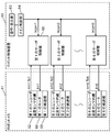
- FIG. 1 is a diagram showing a schematic configuration of a vertical articulated 6-axis robot in the present embodiment.
- FIG. 2 is a block diagram showing a configuration relating to position control of the vertically articulated robot in the present embodiment.
- FIG. 3 is a block diagram showing a configuration of a conventional servo control unit.
- FIG. 4 is a diagram for explaining a vector of a conventional motor command current Im.
- FIG. 5 is a diagram showing details of the d-axis addition 0 block of FIG.
- FIG. 6 is a block diagram showing a configuration of a conventional servo control unit.
- FIG. 7 is a diagram showing details of the d-axis addition 1 block of FIG.
- FIG. 8 is a flowchart for explaining the operation in FIG. FIG.
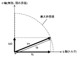
- FIG. 9 is a diagram for explaining a vector of a conventional motor command current.
- FIG. 10 is a diagram for explaining that the conventional motor command current exceeds the maximum allowable value.
- FIG. 11 is a flowchart of overload detection in the present embodiment.
- FIG. 12 is a diagram showing a motor time limit curve in the present embodiment.
- FIG. 13 is a block diagram showing the configuration of the servo control unit in the present embodiment.
- FIG. 14 is a diagram showing details of the d-axis addition two blocks in FIG.
- FIG. 15 is a flowchart for explaining the operation in FIG.
- FIG. 16 is a diagram for explaining a current vector when Ia2 ⁇ Iath2 is satisfied.
- FIG. 17 is a diagram for explaining a vector of motor command current Im in the present embodiment.
- FIG. 18 is a diagram showing transitions of the overload detection value, the absolute value of the motor command current, and the d-axis current addition set value in the present embodiment.
- FIG. 1 is a diagram showing a schematic configuration of a vertical articulated 6-axis robot according to the present embodiment.
- the vertical articulated 6-axis robot is composed of a robot bot mechanism 61 and a robot controller 62.
- the robot mechanism 61 has a plurality of arms and joint axes (not shown), and drives each arm using a speed reducer provided in the vicinity of each joint axis.
- FIG. 2 is a block diagram showing the internal configuration of the robot mechanism 61 and the robot controller 62. In particular, a configuration related to position control of a vertical articulated 6-axis robot is described.
- an operation / display unit 63 receives an instruction regarding movement of the arm or the like of the robot mechanism 61.
- the main control unit 64 stores a movement trajectory of the arm of the robot mechanism 61.
- the operation / display unit 63 receives an instruction, it outputs position commands ⁇ com1 to ⁇ com6 of each axis (for example, 6 axes) of the robot to each axis of the robot according to the movement trajectory corresponding to the instruction.
- the first servo control unit 65 to the sixth servo control unit of each axis of the robot control the first motor 66 to the sixth motor in the robot mechanism 61 so as to follow the position command.
- Each motor is provided with a speed reducer 53.
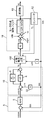
- FIG. 3 is a block diagram showing a configuration of a conventional servo control unit.
- the position control block 6 multiplies the difference value between the position command ⁇ com and the motor position feedback ⁇ m by a position proportional gain 5 to generate a speed loop command ⁇ com.
- the motor position feedback ⁇ m is obtained from an encoder 51 that is a position detector attached to the motor.
- the speed control block 10 multiplies the difference value between the speed loop command ⁇ com and the motor speed feedback ⁇ m by a speed proportional gain 8.
- the motor speed footback ⁇ m is obtained by differentiating the motor position feedback ⁇ m by the differential element 32. Further, the product of the difference value multiplied by the speed integral gain 9 is added to the value multiplied by the speed proportional gain 8 to generate the motor torque current command Iq.
- field weakening control when the motor is driven at high speed, field weakening control may be required.
- the motor back electromotive force that increases in proportion to the motor rotation can be weakened. That is, since the difference between the motor back electromotive force and the power supply voltage is maintained even during high-speed rotation, it is possible to pass a current through the motor and to drive the motor.
- the field weakening control is realized by vector addition of the field weakening current command Id0 of the motor reactive current component to the motor torque current command Iq.
- the motor command current Im can be calculated by the following (Formula 1).
- FIG. 4 is a vector diagram showing (Equation 1).
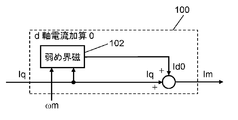
- FIG. 5 is a block diagram showing details of the d-axis current addition 0 block 100.
- the field weakening current command Id0 is calculated using the motor speed feedback ⁇ m and the motor torque current command Iq. As the motor driving speed and torque increase, it is necessary to increase the effect of field weakening (suppress the back electromotive force of the motor more). In order to increase the effect of the field weakening, it is necessary to increase the field weakening current command Id0.
- the field weakening current command Id0 can be calculated by, for example, (Equation 2) below.
- Id0 k1 ⁇ ⁇ m + k2 ⁇ Iq (Formula 2)
- k1 speed proportional coefficient
- k2 torque proportional coefficient
- Patent Document 1 the d-axis current addition value Id1 is determined in accordance with the temperature sensor and the motor torque current command Iq, and the motor is heated by flowing the reactive current component even when the motor is stopped. Thereby, the method of heating the reduction gear grease and reducing the viscous friction of the reduction gear grease has been proposed.
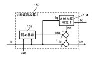
- FIG. 6 is a block diagram showing a configuration of a conventional servo control unit. The difference from FIG. 3 is that the encoder 52 has a built-in temperature sensor and outputs a temperature sensor value Tc, and a d-axis current addition 1 block 150 is provided instead of the d-axis current addition 0 block 100. It is a point.
- FIG. 7 is a block diagram showing details of the d-axis current addition 1 block 150.
- FIG. 8 is a flowchart showing the operation of the d-axis current addition 1 block 150.
- step 8-1 of FIG. 8 a field weakening current command Id0 is calculated. Step 8-1 is executed in the field weakening block 102 of FIG.
- step 8-2 it is determined whether the temperature sensor value Tc is less than the temperature sensor threshold value Tcth. If the temperature sensor value Tc is less than the temperature sensor threshold value Tcth, the process proceeds to step 8-3. Otherwise, the process proceeds to step 8-5.
- step 8-3 it is determined whether the absolute value of the motor torque current command Iq is less than the motor torque current threshold value Iqth. If the absolute value of the motor torque current command Iq is less than the motor torque current threshold value Iqth, the process proceeds to step 8-4. Otherwise, the process proceeds to step 8-5.
- step 8-4 the d-axis current addition set value Id_add is set to the d-axis current addition value Id1.
- Step 8-5 “0” is set to the shaft current addition value Id1.
- steps 8-2 to 8-5 are executed in the d-axis addition determination 1 block 104 in FIG.
- step 8-6 the motor command current Im is calculated by the following (formula 3).
- the reduction gear grease solidified at a low temperature can be heated to reduce the viscous friction of the reduction gear grease.
- the absolute value Ia of the motor command current Im can be calculated by the following (formula 4).
- the absolute value Ia of the motor command current Im may have already reached the maximum allowable value before the d-axis current addition value Id1 is added. Even if the absolute value of the motor torque current command Iq is less than the motor torque current threshold value Iqth, the absolute value Ia of the motor command current Im may reach the Im maximum allowable value by adding the field weakening current command Id0. is there.
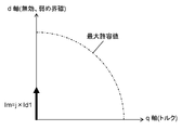
- the absolute value Ia of the motor command current Im exceeds the Im maximum allowable value as shown in FIG.
- the overload detection function is a function for detecting an overload in order to control so that the time integrated value of the absolute value Ia of the motor command current Im does not exceed the limit value of the temperature rise of the winding of the motor.
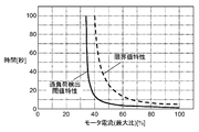
- FIG. 12 shows a motor time characteristic curve.
- the vertical axis of the motor time characteristic curve is the motor current output time
- the horizontal axis is the motor current value (maximum ratio).
- the broken line in FIG. 12 indicates the limit value characteristic.
- the limit value characteristic indicates the time when the temperature rise of the motor winding reaches the limit value and the motor current value. That is, the motor temperature rise reaches the limit value when the motor current output time reaches about 100 seconds when the motor current value is 40%. When the motor current value is 50%, the output time of the motor current has reached about 25 seconds. When the motor current value is 70%, the motor current output time has reached about 8 seconds.
- overload detection is performed so that the time integrated value of the absolute value Ia of the motor command current Im is below this limit value.
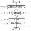
- FIG. 11 is a flowchart of overload detection. This process is executed every fixed period ⁇ T.
- step 11-1 the overload detection value OLdet is obtained by the following (formula 5).
- OLdet OLdet (n ⁇ 1) + (Ia ⁇ Iath) ⁇ ⁇ T (Formula 5)
- Iath Overload detection current threshold value
- ⁇ T Overload detection cycle
- this overload detection value OLdet is compared with the first overload threshold value OLth, and when the following condition (Equation 6) is satisfied, it is determined that the overload is detected.
- step 11-2 If the determination in step 11-2 is “Y”, it is determined that the vehicle is overloaded, and the motor is stopped in step 11-3. Further, an abnormality is displayed in step 11-4, and the overload detection process is terminated.
- the abnormality display displays “overload detection” on the operation / display unit 63 shown in FIG. 2 in order to notify the user of the abnormality.
- step 11-2 If the determination in step 11-2 is “N”, it is determined that there is no overload condition, and the overload detection process is terminated.
- the solid line in FIG. 12 shows the overload detection threshold characteristic.
- the overload detection threshold characteristic (solid line) is set to be lower than the limit value characteristic (broken line). This indicates that the method for calculating the overload detection value OLdet shown in (Equation 5) is appropriate.
- Kt Motor torque constant Iq: Motor current ⁇ m: Motor angular acceleration (differential value of ⁇ m) ⁇ m: Motor angular velocity Jm: Motor inertia (rotor + reducer primary side)
- D Coefficient of viscous friction
- ⁇ Dynamic friction torque
- ⁇ dyn Dynamic torque (sum of gravity torque, inertial force, centrifugal force, Coriolis force)
- ⁇ dis collision torque
- the dynamic friction torque ⁇ can be calculated by the following (formula 9).
- the d-axis current addition value Id1 is added here as a countermeasure against low temperature, the absolute value Ia of the motor command current Im further increases, and the overload detection value OLdet further increases. If the overload detection value OLdet increases until the condition of (Equation 6) is satisfied, an overload detection error occurs and the control device stops.
- the first servo control unit 65 in order to reduce the viscous friction of the reduction gear grease at a low temperature without causing motor demagnetization and overload detection error, the first servo control unit 65 according to the present embodiment will be described below.
- FIG. 13 is a block diagram showing a configuration of the first servo control unit 65 of the present embodiment. The difference from FIG. 6 is that an overload detection block 204 is added and that a d-axis current addition 2 block 200 is provided instead of the d-axis current addition 1 block 150.
- FIG. 14 is a block diagram showing details of the d-axis current addition 2 block 200. The difference from FIG. 7 is that an absolute value calculation block 205 before addition is provided.
- FIG. 15 is a flowchart showing the operation of FIG. 14, that is, the robot control method of the present embodiment.
- step 15-1 the field weakening current block Id0 is calculated by the field weakening block 102 in FIG.
- step 15-2 the absolute value Ia2 of the motor command current Im before addition of the d-axis current is obtained by (Equation 10) in the absolute value calculation block 205 before addition in FIG.
- step 15-3 the temperature sensor value Tc is compared with the temperature sensor threshold value Tcth. If the temperature sensor value Tc is less than the temperature sensor threshold value Tcth, the process proceeds to step 15-4. Otherwise, the process proceeds to step 15-7.
- step 15-4 Ia2 calculated in step 15-2 is compared with the current absolute value threshold value Iath2. If Ia2 is less than Iath2, the process proceeds to step 15-5. Otherwise, the process proceeds to step 15-7.
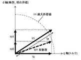
- FIG. 16 shows a current vector when the absolute value Ia2 of the motor command current Im before the d-axis current addition is less than the current absolute value threshold value Iath2.
- step 15-4 it is confirmed that the absolute value Ia of the motor command current Im does not exceed the maximum allowable value even if the d-axis current addition value Id1A described later is added to the motor command current Im before the d-axis current is added. ing.
- step 15-5 the overload detection value OLdet is compared with the second overload threshold value OLth2.
- the overload detection value OLdet is calculated by the overload detection block 204 in FIG. If the overload detection value OLdet is less than the second overload threshold OLth2, the process proceeds to step 15-6, and otherwise, the process proceeds to step 15-7. Note that the value of the second overload threshold OLth2 is set lower than the value of the first overload threshold OLth.
- step 15-6 the d-axis current addition set value Id_addA is set to the d-axis current addition value Id1A.
- step 15-7 “0” is set to the d-axis current addition value Id1A.
- Steps 15-3 to 15-7 are executed in the d-axis addition determination 2 block 202 in FIG.
- step 15-8 the motor command current Im is calculated by the following (formula 11).
- FIG. 17 shows the motor command current Im calculated by (Equation 11).
- Id1A is added to FIG. 16, but it can be seen that the absolute value Ia of the motor command current Im does not exceed the maximum allowable value.
- step 15-3 Tc ⁇ Tch
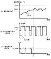
- FIG. 18A shows the overload detection value
- FIG. 18B shows the absolute value of the motor command current
- FIG. 18C shows the d-axis current addition set value.
- step 15-6 and step 15-8 are executed and the d-axis current is added. Therefore, the overload detection value OLdet calculated by (Equation 5) tends to increase, and tends to increase if viewed largely until time t1.
- the robot control method is a robot control method for controlling the movement of a robot arm using a servo motor via a speed reducer, and the temperature is equal to or lower than a predetermined value.
- a step of determining that the absolute value of the motor current command is not more than a predetermined value, and a step of determining that the overload detection level is not more than the predetermined value, and adding the d-axis current It is characterized by.
- the second to fifth servo control units included in the robot control device 62 of FIG. 2 have the same configuration as the first servo control unit 65 described with reference to FIGS. Therefore, the description is omitted.
- the robot control method of the present disclosure can reduce the viscous friction of the reducer grease at low temperatures by generating heat without causing motor demagnetization and overload error. Useful in application.
- Position proportional gain 6 Position control block 8 Speed proportional gain 9 Speed integral gain 10 Speed control block 18 Block indicating motor and external force 32 Differentiating element 51 Encoder 52 Encoder 53 Reducer 61 Robot mechanism 62 Robot controller 62 Robot controller 63 Operation / display unit 64 Main control unit 65 Servo control unit 66 Motor 100 d-axis current addition 0 block 102 Weak field block 104 d-axis addition determination 1 block 150 d-axis current addition 1 block 200 d-axis current addition 2 block 202 d-axis addition determination 2 block 204 Overload detection block 205 Absolute value calculation block before addition ⁇ m Motor speed feedback ⁇ com Position command ⁇ m Position feedback ⁇ L Reducer output position ⁇ com Speed loop command Im Motor command current ⁇ m Motor generated torque ⁇ dyn Dynamic torque (sum of gravity torque, inertial force, centrifugal force, Coriolis force) ⁇ Dynamic friction torque ⁇ dis Collision torque Tc Temperature sensor output value Iq Motor torque current command Id0 Field weaken
Landscapes
- Engineering & Computer Science (AREA)
- Power Engineering (AREA)
- Robotics (AREA)
- Mechanical Engineering (AREA)
- Control Of Ac Motors In General (AREA)
- Manipulator (AREA)
- Control Of Electric Motors In General (AREA)
- Protection Of Generators And Motors (AREA)
- Numerical Control (AREA)
Abstract
サーボモータを用いてロボットアームの運動制御を行うロボットの制御方法であって、外気温が所定値以下であり(ステップ15-3)、かつモータ電流指令の絶対値が所定値以下であり(ステップ15-4)、かつ過負荷検出値が所定値以下(ステップ15-5)である場合に、前記モータ電流指令にd軸電流を加算するようにした(ステップ15-6、ステップ15-8)、ロボットの制御方法。
Description
本開示は、ロボットの制御方法に関し、低温時の減速機グリス粘性摩擦増大に起因するロボット動作不良を減少させるロボットの制御方法に関する。
減速機を介してサーボモータを駆動させて部品を動作させる制御機器においては、気温が5℃を下回る低温時に、減速機に使用されているグリス(以下、「減速機グリス」と記載する)の粘性が高くなって粘性摩擦が増大することがある。そうすると、サーボモータの発生トルクが摩擦で相殺され、駆動トルクが不足して満足な性能が得られなくなる場合がある。
そこで、サーボモータのトルクを発生させる電流(以下q軸電流という)ではなく、無効成分電流(以下d軸電流という)を流し、モータを発熱させることにより、減速機グリスの粘性摩擦を減少させる方法が提案されている(例えば、特許文献1参照)。
しかしながら、上記の特許文献1の技術では、温度センサとq軸電流の大きさとから加算するd軸電流の大きさを決定している。そのため、元々弱め界磁制御でd軸電流を流している場合は、更にd軸電流が追加されることになり、皮相電流(q軸電流とd軸電流とのベクトル和)が許容最大値を超えてしまって、モータ磁石の減磁を招く恐れがある。
また、一般に、ロボットを制御する制御装置には、減速機の故障や外部との接触等によって生じる過負荷によるモータの過加熱を防ぐために、過負荷検出機能が搭載されている。過負荷検出には皮相電流が用いられるため、過負荷検出機能を考慮せずにd軸電流を加算すると、皮相電流が増加し、誤って過負荷が検出されることがある。そうすると、モータの過加熱を防ぐために、ロボットが停止する可能性がある。
本開示はかかる点に鑑みてなされたもので、その目的は、モータ減磁および過負荷検出エラーを発生させることなく、モータの発熱により、低温時における減速機グリスの粘性摩擦を低減することができるロボットの制御方法を提供することにある。
上記の目的を達成するために、ここに開示する技術では、モータ電流指令の絶対値および過負荷検出レベルが所定値以下の場合にd軸電流を加算する。これにより、モータ減磁および過負荷を発生させることなく、モータの発熱により、低温時の減速機グリス摩擦低減を行う。そのため、皮相電流が許容最大値を超えることなく、さらに過負荷検出エラーによるロボット停止を発生させることなく、低温時における減速機グリスの粘性摩擦を低減することができる。
以上説明したように、本開示のロボットの制御方法によると、モータ減磁および過負荷エラーを発生させることなく、モータの発熱により、低温時における減速機グリスの粘性摩擦を低減することができる。
以下、本実施の形態を図面に基づいて詳細に説明する。以下の好ましい実施形態の説明は、本質的に例示に過ぎない。
図1は、本実施の形態に係る垂直多関節6軸ロボットの概略構成を示す図である。同図に示すように、垂直多関節6軸ロボットは、ロ ボットメカ61とロボット制御装置62とから構成される。ここで、ロボットメカ61は、図示しない複数のアームおよび関節軸を有しており、各関節軸の近傍に設けられた減速機を用いて各アームを駆動するものである。
図2は、ロボットメカ61とロボット制御装置62との内部構成を示すブロック図である。ここでは特に、垂直多関節6軸ロボットの位置制御に関する構成を記載している。
図2に示すように、ロボット制御装置62の内部には、操作・表示部63、メイン制御部64、および、第1のサーボ制御部65から第6のサーボ制御部が設けられている。操作・表示部63は、ロボットメカ61のアーム等の移動に関する指示を受け付ける。メイン制御部64は、ロボットメカ61のアーム等の移動の軌跡を記憶している。そして、操作・表示部63が指示を受け付けると、その指示に対応する移動の軌跡に従い、ロボットの各軸(例えば6軸)の位置指令θcom1からθcom6を、ロボットの各軸に出力する。すると、その位置指令に追従するように、ロボットの各軸の第1のサーボ制御部65から第6のサーボ制御部が、ロボットメカ61内の第1のモータ66から第6のモータをそれぞれ制御する。各モータのそれぞれには減速機53が設けられている。
ここでは、本実施形態のサーボ制御部65について説明する前に、従来のサーボ制御部について説明する。
図3は、従来のサーボ制御部の構成を示すブロック図である。位置制御ブロック6は、位置指令θcomとモータ位置フィードバックθmとの差分値に、位置比例ゲイン5を乗じて、速度ループ指令ωcomを生成する。モータ位置フィードバックθmは、モータに取り付けられた位置検出器であるエンコーダ51から得られる。
速度制御ブロック10は、速度ループ指令ωcomとモータ速度フィードバックωmとの差分値に、速度比例ゲイン8を乗ずる。モータ速度フィートバックωmは、モータ位置フィードバックθmを微分要素32で微分して得られる。さらにその差分値の積分値に速度積分ゲイン9を乗じたものを、速度比例ゲイン8を乗じた値に加算して、モータトルク電流指令Iqを生成する。
ここで、モータを高速回転で駆動する場合、弱め界磁制御が必要となる場合がある。弱め界磁制御を行うと、モータ回転に比例して増大するモータ逆起電力を弱めることができる。すなわち高速回転時でもモータ逆起電力と電源電圧との差が保たれるので、モータに電流を流すことが可能となり、モータを駆動できることになる。
通常、弱め界磁制御は、モータ無効電流成分の弱め界磁電流指令Id0をモータトルク電流指令Iqにベクトル加算することで実現する。このときモータ指令電流Imは以下の(式1)で計算できる。
Im=Iq+j×Id0 (式1)
ただし、j:虚数単位(無効成分を表す)
この計算は、図3のd軸電流加算0ブロック100で実行される。(式1)をベクトル図で示すと図4となる。図5はd軸電流加算0ブロック100の詳細を示したブロック図である。
ただし、j:虚数単位(無効成分を表す)
この計算は、図3のd軸電流加算0ブロック100で実行される。(式1)をベクトル図で示すと図4となる。図5はd軸電流加算0ブロック100の詳細を示したブロック図である。
図5に示すように、弱め界磁電流指令Id0は、モータ速度フィードバックωmとモータトルク電流指令Iqとを用いて計算される。モータ駆動の速度およびトルクが大きくなるほど、弱め界磁の効果を大きくする(モータの逆起電力をより抑える)必要がある。弱め界磁の効果を大きくするためには、弱め界磁電流指令Id0を大きくする必要がある。弱め界磁電流指令Id0は、例えば以下の(式2)で計算できる。
Id0=k1×ωm+k2×Iq (式2)
ただし、k1:速度比例係数、 k2:トルク比例係数
ここで、ロボットが停止状態であると、重力が印加されていない軸ではωm=0、Iq=0となり、Id0=0、Im=0となる場合がある。この場合はモータに電流が流れないので、モータは発熱しない。低温状態で減速機グリスが固まっている場合は固まった減速機グリスを加熱することができない。
ただし、k1:速度比例係数、 k2:トルク比例係数
ここで、ロボットが停止状態であると、重力が印加されていない軸ではωm=0、Iq=0となり、Id0=0、Im=0となる場合がある。この場合はモータに電流が流れないので、モータは発熱しない。低温状態で減速機グリスが固まっている場合は固まった減速機グリスを加熱することができない。
そこで特許文献1では、温度センサ及びモータトルク電流指令Iqに従ってd軸電流加算値Id1を決定し、モータ停止時でも無効電流成分を流すことでモータを発熱させる。これにより、減速機グリスを加熱して、減速機グリスの粘性摩擦を減少させる方法が提案されている。
図6は、従来のサーボ制御部の構成を示すブロック図である。図3との相違は、エンコーダ52が温度センサを内蔵しており、温度センサ値Tcを出力している点、およびd軸電流加算0ブロック100の代わりに、d軸電流加算1ブロック150を備えている点である。
図7は、d軸電流加算1ブロック150の詳細を示したブロック図である。図8は、d軸電流加算1ブロック150の動作を示したフローチャートである。
図8のステップ8-1では、弱め界磁電流指令Id0を計算する。ステップ8-1は、図7の弱め界磁ブロック102で実行される。
ステップ8-2では、温度センサ値Tcが温度センサ閾値Tcth未満であるか判断する。温度センサ値Tcが温度センサ閾値Tcth未満であればステップ8-3へ進み、それ以外ではステップ8-5へ進む。
ステップ8-3では、モータトルク電流指令Iqの絶対値がモータトルク電流閾値Iqth未満であるか判断する。モータトルク電流指令Iqの絶対値がモータトルク電流閾値Iqth未満であればステップ8-4へ進み、それ以外ではステップ8-5へ進む。
ステップ8-4ではd軸電流加算値Id1にd軸電流加算設定値Id_addを設定する。
一方、ステップ8-5では軸電流加算値Id1に「0」を設定する。
以上、ステップ8-2~8-5は、図7のd軸加算判定1ブロック104で実行される。
ステップ8-6では、モータ指令電流Imが以下の(式3)で計算される。
Im=Iq+j×(Id0 + Id1) (式3)
図9は、ωm=0、Iq=0およびId0=0の状態(すなわち、ロボットが停止かつ重力が印加されていない状態)で、温度センサ出力値Tc<Tcth、すなわち低温の場合のベクトル図を示している。このとき、(式2)および(式3)より、モータ指令電流Im=j×Id1となるので、モータに無効成分電流が流れ、モータが加熱されることになる。
図9は、ωm=0、Iq=0およびId0=0の状態(すなわち、ロボットが停止かつ重力が印加されていない状態)で、温度センサ出力値Tc<Tcth、すなわち低温の場合のベクトル図を示している。このとき、(式2)および(式3)より、モータ指令電流Im=j×Id1となるので、モータに無効成分電流が流れ、モータが加熱されることになる。
モータが加熱されることにより、低温で固まった減速機グリスを加熱して、減速機グリスの粘性摩擦を減少させることができる。
しかしながら、この方法では、元々弱め界磁でd軸電流を流している場合(Id0≠0の場合)、モータ指令電流Imが最大許容値を越えたり、過負荷エラーが発生する可能性がある。
モータ指令電流Imの絶対値Iaは以下の(式4)で計算できる。
Ia=|Im|=√(Iq2+(Id0+Id1)2) (式4)
モータに流せる電流には最大許容値がある。モータ電流の絶対値が最大許容値を越えると、モータの巻線の損傷やモータの磁石の減磁が発生する恐れがある。
モータに流せる電流には最大許容値がある。モータ電流の絶対値が最大許容値を越えると、モータの巻線の損傷やモータの磁石の減磁が発生する恐れがある。
なお、d軸電流加算値Id1が加算される前に、既にモータ指令電流Imの絶対値Iaが最大許容値に到達している場合がある。モータトルク電流指令Iqの絶対値がモータトルク電流閾値Iqth未満であっても、弱め界磁電流指令Id0が加算されることによりモータ指令電流Imの絶対値IaがIm最大許容値に到達する場合がある。
ここへ低温対策のための無効電流であるd軸電流加算値Id1を加算すると、図10に示す様に、モータ指令電流Imの絶対値IaはIm最大許容値を越えてしまう。
つまり、特許文献1のように、モータトルク電流指令Iqの監視だけでd軸電流加算値Id1を決定すると、モータ指令電流Imの絶対値IaがIm最大許容値を越えてしまうことがある。そうすると、モータの巻線の損傷やモータの磁石の減磁が発生する可能性がある。
続いて、過負荷検出機能について説明する。過負荷検出機能は、モータ指令電流Imの絶対値Iaの時間積算値が、モータの巻線の温度上昇の限界値を超えない様に制御するために、過負荷を検出する機能である。
図12は、モータ時限特性曲線を示す。モータ時限特性曲線の縦軸はモータ電流の出力時間であり、横軸はモータ電流値(最大比)である。図12の破線は、限界値特性を示している。限界値特性は、モータの巻線の温度上昇が限界値に達したときの時間およびモータ電流値を示している。すなわち、モータの温度上昇が限界値に達するのは、モータ電流値が40%の場合は、モータ電流の出力時間が約100秒に達したときである。モータ電流値が50%の場合は、モータ電流の出力時間が約25秒に達したときである。モータ電流値が70%の場合は、モータ電流の出力時間が約8秒に達したときである。
そこで、過負荷検出機能では、モータ指令電流Imの絶対値Iaの時間積算値がこの限界値以下になる様に過負荷検出を行う。
図11は、過負荷検出のフローチャートである。この処理は一定周期ΔT毎に実行されるものとする。
ステップ11-1で、過負荷検出値OLdetを以下の(式5)で求める。
OLdet=OLdet(n-1)+(Ia-Iath)×ΔT (式5)
ただし、Iath:過負荷検出電流閾値
ΔT:過負荷検出周期
なお、(式5)のOLdet(n-1)は、1周期前の過負荷検出値(OLdet)である。ステップ11-2で、この過負荷検出値OLdetを第1過負荷閾値OLthと比較し、下記(式6)の条件が成立した時、過負荷と判定する。
ただし、Iath:過負荷検出電流閾値
ΔT:過負荷検出周期
なお、(式5)のOLdet(n-1)は、1周期前の過負荷検出値(OLdet)である。ステップ11-2で、この過負荷検出値OLdetを第1過負荷閾値OLthと比較し、下記(式6)の条件が成立した時、過負荷と判定する。
OLdet≧OLth (式6)
ステップ11-2の判定が「Y」である場合、過負荷状態と判定し、ステップ11-3でモータを停止する。さらに、ステップ11-4で異常表示を行い、過負荷検出の処理を終了する。なお、異常表示は、ユーザに異常を通知するために、図2に示した操作・表示部63に「過負荷検出」と表示する。
ステップ11-2の判定が「Y」である場合、過負荷状態と判定し、ステップ11-3でモータを停止する。さらに、ステップ11-4で異常表示を行い、過負荷検出の処理を終了する。なお、異常表示は、ユーザに異常を通知するために、図2に示した操作・表示部63に「過負荷検出」と表示する。
ステップ11-2の判定が「N」の場合、過負荷状態では無いとの判定し、過負荷検出の処理を終了する。
図12の実線は、過負荷検出閾値特性を示す。過負荷検出閾値特性は、一例として、Iath=33およびOLth=100とした場合に、(式6)でOLdet=OLthとなるときの時間およびモータ電流値(最大比)を示している。過負荷検出閾値特性(実線)は限界値特性(破線)を下回る様に設定されている。これは、(式5)で示す過負荷検出値OLdetの計算方法が妥当である事を示している。
図6に戻り、気温が低い場合に生じる減速機グリスの粘性摩擦の問題について説明する。
図6におけるモータ及び外力を示すブロック18を数式で表したものが下記の(式7)および(式8)である。減速機53が剛体であると仮定した場合、モータ駆動側から見たモータ発生トルクτmは(式7)で表され、負荷側から見たモータ発生トルクτmは(式8)で表される。
(式7)でImではなく、Iqを用いているのは、トルク発生に有効な成分はIqだからである。(式8)で減速機出力位置θLではなく、モータの位置フィードバックθmの微分値ωmを用いているのは、減速機53が剛体であると仮定しているので、減速機出力位置θLは単に位置フィードバックθmに減速比(比例係数)を乗じた値になるからである。
τm=Kt×Iq (式7)
τm=τdyn+τdis+Jm×αm+D×ωm+τμ (式8)
ただし、
Kt:モータトルク定数
Iq:モータ電流
αm:モータ角加速度(ωmの微分値)
ωm:モータ角速度
Jm:モータイナーシャ(ロータ+減速機1次側)
D:粘性摩擦係数
τμ:動摩擦トルク
τdyn:動力学トルク(重力トルク、慣性力、遠心力、コリオリ力の和)
τdis:衝突トルク
ここで、動摩擦トルクτμは以下の(式9)で計算できる。
τm=τdyn+τdis+Jm×αm+D×ωm+τμ (式8)
ただし、
Kt:モータトルク定数
Iq:モータ電流
αm:モータ角加速度(ωmの微分値)
ωm:モータ角速度
Jm:モータイナーシャ(ロータ+減速機1次側)
D:粘性摩擦係数
τμ:動摩擦トルク
τdyn:動力学トルク(重力トルク、慣性力、遠心力、コリオリ力の和)
τdis:衝突トルク
ここで、動摩擦トルクτμは以下の(式9)で計算できる。
τμ=Kμ×sgn (式9)
ただし、Kμ:動摩擦の大きさ
sgn:1(ωm>0)、または0(ωm=0)、または-1(ωm<0)
気温が低下して特に5℃以下になると、(式8)の粘性摩擦係数Dが飛躍的に増大する。そのため、負荷側の駆動に必要なモータ発生トルクτmも増大し、そのトルクを発生させるモータトルク電流指令Iqも増大する。その結果、(式4)で計算されるモータ指令電流Imの絶対値Iaも増大する。
ただし、Kμ:動摩擦の大きさ
sgn:1(ωm>0)、または0(ωm=0)、または-1(ωm<0)
気温が低下して特に5℃以下になると、(式8)の粘性摩擦係数Dが飛躍的に増大する。そのため、負荷側の駆動に必要なモータ発生トルクτmも増大し、そのトルクを発生させるモータトルク電流指令Iqも増大する。その結果、(式4)で計算されるモータ指令電流Imの絶対値Iaも増大する。
つまり、気温が20℃前後の常温時とロボットの動作が同じであっても、5℃以下の低温時には、モータ指令電流Imの絶対値Iaが増加し、(式6)で計算される過負荷検出値OLdetも増大する。
ここへ低温対策として、d軸電流加算値Id1を加算すると、モータ指令電流Imの絶対値Iaがさらに増大し、過負荷検出値OLdetもさらに増大する。そして(式6)の条件が成立するまで過負荷検出値OLdetが増大すると、過負荷検出エラーが発生し制御機器が停止することになる。
そこで、モータ減磁および過負荷検出エラーを発生させることなく、低温時における減速機グリスの粘性摩擦を低減するために、以下に本実施の形態に係る第1のサーボ制御部65について説明する。
図13は、本実施の形態の第1のサーボ制御部65の構成を示すブロック図である。図6との相違は、過負荷検出ブロック204を追加した点、および、d軸電流加算1ブロック150の代わりにd軸電流加算2ブロック200を備える点である。
図14は、d軸電流加算2ブロック200の詳細を示したブロック図である。図7との相違は、加算前絶対値演算ブロック205を設けた点である。
図15は、図14の動作、すなわち本実施の形態のロボットの制御方法を示したフローチャートである。
ステップ15-1では、図14の弱め界磁ブロック102で弱め界磁電流指令Id0を計算する。
ステップ15-2では、図14の加算前絶対値演算ブロック205にて、d軸電流加算前のモータ指令電流Imの絶対値Ia2を(式10)で求める。
Ia2 =√(Iq2+Id02) (式10)
ステップ15-3では、温度センサ値Tcと温度センサ閾値Tcthとを比較する。温度センサ値Tcが温度センサ閾値Tcth未満であればステップ15-4へ進み、それ以外ではステップ15-7へ進む。
ステップ15-3では、温度センサ値Tcと温度センサ閾値Tcthとを比較する。温度センサ値Tcが温度センサ閾値Tcth未満であればステップ15-4へ進み、それ以外ではステップ15-7へ進む。
ステップ15-4では、ステップ15-2で算出したIa2と電流絶対値閾値Iath2とを比較する。Ia2がIath2未満であればステップ15-5へ進み、それ以外ではステップ15-7へ進む。
ここで、図16は、d軸電流加算前のモータ指令電流Imの絶対値Ia2が電流絶対値閾値Iath2未満である場合の電流ベクトルを示している。ステップ15-4では、d軸電流加算前のモータ指令電流Imに後述するd軸電流加算値Id1Aが加算されても、モータ指令電流Imの絶対値Iaが最大許容値を越えないことを確認している。
次に、ステップ15-5では、過負荷検出値OLdetと第2過負荷閾値OLth2とを比較する。過負荷検出値OLdetは図13の過負荷検出ブロック204で計算される。過負荷検出値OLdetが第2過負荷閾値OLth2未満であればステップ15-6へ進み、それ以外ではステップ15-7へ進む。なお、第2過負荷閾値OLth2の値は第1過負荷閾値OLthの値より低く設定されている。
ステップ15-6では、d軸電流加算値Id1Aにd軸電流加算設定値Id_addAを設定する。
一方、ステップ15-7では、d軸電流加算値Id1Aに「0」を設定する。
以上ステップ15-3~15-7は、図14のd軸加算判定2ブロック202で実行される。
ステップ15-8では、モータ指令電流Imが以下の(式11)で計算される。
Im=Iq+j×(Id0 + Id1A) (式11)
図17は、(式11)で計算されたモータ指令電流Imを示している。図17では、図16にId1Aが加算されるが、モータ指令電流Imの絶対値Iaが最大許容値を越えないことがわかる。
図17は、(式11)で計算されたモータ指令電流Imを示している。図17では、図16にId1Aが加算されるが、モータ指令電流Imの絶対値Iaが最大許容値を越えないことがわかる。
続いて図18(a)~(c)を用いて、本実施の形態の過負荷検出について説明する。ここでは、ステップ15-3の条件(Tc<Tch)は常に成立しているものとする。
図18(a)は過負荷検出値を示し、図18(b)はモータ指令電流の絶対値を示し、(c)はd軸電流加算設定値を示している。ここでは、時間t1までは、ステップ15-5の条件(OLdet<OLth2)が成立している場合を例に説明する。
時間t1までは、ステップ15-4の条件(Ia2<Iath2)が成立している間は、ステップ15-6およびステップ15-8の処理が実行され、d軸電流が加算される。それ故、(式5)で計算される過負荷検出値OLdetは増加する割合が多く、時間t1までは大きく見れば増加傾向にある。
時間t1でステップ15-5の条件が成立しなくなると、以後はステップ15-7でId1A=0となり、d軸電流が加算されない。そのため、d軸電流加算による過負荷検出値OLdetの増加傾向がなくなるので、過負荷検出値OLdetが第1過負荷閾値OLthを越えることを防止することができる。すなわち、過負荷検出エラーの発生を防止することができる。
以上説明したように、本実施の形態のロボットの制御方法は、減速機を介したサーボモータを用いてロボットアームの運動制御を行うロボットの制御方法であって、気温が所定値以下であることを判定するステップと、モータ電流指令の絶対値が所定値以下であることを判定するステップと、過負荷検出レベルが所定値以下であることを判定するステップを備え、d軸電流を加算することを特徴とする。
なお、図2のロボット制御装置62に含まれる第2のサーボ制御部から第5のサーボ制御部は、それぞれ、図13から図18で説明した第1のサーボ制御部65と同様の構成であるため、説明を省略する。
本開示のロボット制御方法は、モータ減磁および過負荷エラーを発生させることなく、モータ発熱によって、低温時における減速機グリスの粘性摩擦を低減させることができるので、溶接ロボットなどの産業用ロボットに適用する上で有用である。
5 位置比例ゲイン
6 位置制御ブロック
8 速度比例ゲイン
9 速度積分ゲイン
10 速度制御ブロック
18 モータ及び外力を示すブロック
32 微分要素
51 エンコーダ
52 エンコーダ
53 減速機
61 ロボットメカ
62 ロボット制御装置
63 操作・表示部
64 メイン制御部
65 サーボ制御部
66 モータ
100 d軸電流加算0ブロック
102 弱め界磁ブロック
104 d軸加算判定1ブロック
150 d軸電流加算1ブロック
200 d軸電流加算2ブロック
202 d軸加算判定2ブロック
204 過負荷検出ブロック
205 加算前絶対値演算ブロック
ωm モータ速度フィードバック
θcom 位置指令
θm 位置フィードバック
θL 減速機出力位置
ωcom 速度ループ指令
Im モータ指令電流
τm モータ発生トルク
τdyn 動力学トルク(重力トルク、慣性力、遠心力、コリオリ力の和)
τμ 動摩擦トルク
τdis 衝突トルク
Tc 温度センサ出力値
Iq モータトルク電流指令
Id0 弱め界磁電流指令
Id1 d軸電流加算値
Ia モータ指令電流Imの絶対値
Ia2 d軸電流加算前のモータ指令電流Imの絶対値
Iath 過負荷検出電流閾値
Iath2 電流絶対値閾値(d軸電流加算判定用)
Id1A d軸電流加算値
Id_addA d軸電流加算設定値
OLdet 過負荷検出値
OLth 第1過負荷閾値(過負荷判定用)
OLth2 第2過負荷閾値(d軸電流加算判定用)
Claims (2)
- サーボモータを用いてロボットアームの運動制御を行うロボットの制御方法であって、
気温が所定値以下であり、かつモータ電流指令の絶対値が所定値以下であり、かつ過負荷検出値が所定値以下である場合に、前記モータ電流指令にd軸電流を加算する
ロボットの制御方法。 - 気温が第1の所定値以下であるか判定するステップと、
気温が前記第1の所定値以下である場合に、モータ電流指令の絶対値が第2の所定値以下であるか判定するステップと、
モータ電流指令の絶対値が前記第2の所定値以下である場合に、過負荷検出値が第3の所定値以下であるか判定するステップと、
過負荷検出値が前記第3の所定値以下である場合に、モータ電流指令にd軸電流を加算するステップとを含む
請求項1記載のロボットの制御方法。
Priority Applications (4)
| Application Number | Priority Date | Filing Date | Title |
|---|---|---|---|
| JP2019502882A JP6975886B2 (ja) | 2017-03-01 | 2018-02-19 | ロボットの制御方法 |
| CN201880014523.8A CN110366818B (zh) | 2017-03-01 | 2018-02-19 | 机器人的控制方法 |
| EP18760661.1A EP3576298B1 (en) | 2017-03-01 | 2018-02-19 | Robot control method |
| US16/548,295 US11298819B2 (en) | 2017-03-01 | 2019-08-22 | Robot control method |
Applications Claiming Priority (2)
| Application Number | Priority Date | Filing Date | Title |
|---|---|---|---|
| JP2017-038341 | 2017-03-01 | ||
| JP2017038341 | 2017-03-01 |
Related Child Applications (1)
| Application Number | Title | Priority Date | Filing Date |
|---|---|---|---|
| US16/548,295 Continuation US11298819B2 (en) | 2017-03-01 | 2019-08-22 | Robot control method |
Publications (1)
| Publication Number | Publication Date |
|---|---|
| WO2018159341A1 true WO2018159341A1 (ja) | 2018-09-07 |
Family
ID=63370892
Family Applications (1)
| Application Number | Title | Priority Date | Filing Date |
|---|---|---|---|
| PCT/JP2018/005643 WO2018159341A1 (ja) | 2017-03-01 | 2018-02-19 | ロボットの制御方法 |
Country Status (5)
| Country | Link |
|---|---|
| US (1) | US11298819B2 (ja) |
| EP (1) | EP3576298B1 (ja) |
| JP (1) | JP6975886B2 (ja) |
| CN (1) | CN110366818B (ja) |
| WO (1) | WO2018159341A1 (ja) |
Cited By (3)
| Publication number | Priority date | Publication date | Assignee | Title |
|---|---|---|---|---|
| CN109768748A (zh) * | 2019-03-29 | 2019-05-17 | 广东美的制冷设备有限公司 | 矢量控制系统、控制方法、装置、空调器与存储介质 |
| WO2020173755A1 (de) * | 2019-02-27 | 2020-09-03 | Mahle International Gmbh | Verfahren zum betreiben eines dreiphasigen elektrischen motors und dreiphasiger elektrischer motor |
| JP7442578B2 (ja) | 2022-02-28 | 2024-03-04 | 株式会社デンソーウェーブ | 学習モデル生成方法、学習モデル生成プログラム、学習モデル生成装置、学習用データ生成方法、学習用データ生成プログラム、学習用データ生成装置、推論方法、推論プログラム、推論装置、秤量方法、及び秤量システム |
Families Citing this family (2)
| Publication number | Priority date | Publication date | Assignee | Title |
|---|---|---|---|---|
| WO2021192181A1 (ja) * | 2020-03-26 | 2021-09-30 | 三菱電機株式会社 | 摩擦補償装置、衝突検知装置、トルクフィードフォワード演算装置およびロボット制御装置並びに摩擦補償方法 |
| CN112476423B (zh) * | 2020-11-12 | 2022-03-08 | 腾讯科技(深圳)有限公司 | 机器人的关节电机控制方法、装置、设备及存储介质 |
Citations (4)
| Publication number | Priority date | Publication date | Assignee | Title |
|---|---|---|---|---|
| JPS63127885A (ja) * | 1986-11-18 | 1988-05-31 | 横河電機株式会社 | ロボツトア−ムの温度制御装置 |
| JPH10180662A (ja) * | 1996-12-27 | 1998-07-07 | Tokico Ltd | 工業用ロボット |
| JP2005138606A (ja) * | 2003-11-04 | 2005-06-02 | Toyota Motor Corp | 操舵装置 |
| JP4292871B2 (ja) | 2003-05-29 | 2009-07-08 | 株式会社ジェイテクト | 車両の操舵制御装置 |
Family Cites Families (8)
| Publication number | Priority date | Publication date | Assignee | Title |
|---|---|---|---|---|
| JPH0637903Y2 (ja) * | 1987-02-12 | 1994-10-05 | 坂本文具株式会社 | ホツチキス |
| JP3625901B2 (ja) * | 1995-06-30 | 2005-03-02 | 三菱電機株式会社 | サーボ制御システムの自動適正化方法および装置 |
| JP2005219133A (ja) * | 2004-02-03 | 2005-08-18 | Fanuc Ltd | ロボット用サーボモータ制御装置およびロボット |
| JP5468215B2 (ja) * | 2008-06-09 | 2014-04-09 | ダイキン工業株式会社 | 空気調和機及び空気調和機の製造方法 |
| JP6079786B2 (ja) * | 2012-11-20 | 2017-02-15 | 株式会社安川電機 | モータ駆動システムおよびモータ制御装置 |
| JP6541301B2 (ja) * | 2014-03-28 | 2019-07-10 | キヤノン株式会社 | ロボット装置、ロボット装置の制御方法、ロボット制御プログラム、及び記録媒体 |
| JP2016030403A (ja) | 2014-07-29 | 2016-03-07 | 東芝機械株式会社 | 電動機の制御方法、電動機の制御装置及び成形装置 |
| WO2016178262A1 (ja) * | 2015-05-01 | 2016-11-10 | 三菱電機株式会社 | 電動パワーステアリング制御装置および電動パワーステアリング制御方法 |
-
2018
- 2018-02-19 CN CN201880014523.8A patent/CN110366818B/zh active Active
- 2018-02-19 WO PCT/JP2018/005643 patent/WO2018159341A1/ja unknown
- 2018-02-19 EP EP18760661.1A patent/EP3576298B1/en active Active
- 2018-02-19 JP JP2019502882A patent/JP6975886B2/ja active Active
-
2019
- 2019-08-22 US US16/548,295 patent/US11298819B2/en active Active
Patent Citations (4)
| Publication number | Priority date | Publication date | Assignee | Title |
|---|---|---|---|---|
| JPS63127885A (ja) * | 1986-11-18 | 1988-05-31 | 横河電機株式会社 | ロボツトア−ムの温度制御装置 |
| JPH10180662A (ja) * | 1996-12-27 | 1998-07-07 | Tokico Ltd | 工業用ロボット |
| JP4292871B2 (ja) | 2003-05-29 | 2009-07-08 | 株式会社ジェイテクト | 車両の操舵制御装置 |
| JP2005138606A (ja) * | 2003-11-04 | 2005-06-02 | Toyota Motor Corp | 操舵装置 |
Cited By (3)
| Publication number | Priority date | Publication date | Assignee | Title |
|---|---|---|---|---|
| WO2020173755A1 (de) * | 2019-02-27 | 2020-09-03 | Mahle International Gmbh | Verfahren zum betreiben eines dreiphasigen elektrischen motors und dreiphasiger elektrischer motor |
| CN109768748A (zh) * | 2019-03-29 | 2019-05-17 | 广东美的制冷设备有限公司 | 矢量控制系统、控制方法、装置、空调器与存储介质 |
| JP7442578B2 (ja) | 2022-02-28 | 2024-03-04 | 株式会社デンソーウェーブ | 学習モデル生成方法、学習モデル生成プログラム、学習モデル生成装置、学習用データ生成方法、学習用データ生成プログラム、学習用データ生成装置、推論方法、推論プログラム、推論装置、秤量方法、及び秤量システム |
Also Published As
| Publication number | Publication date |
|---|---|
| EP3576298A1 (en) | 2019-12-04 |
| CN110366818A (zh) | 2019-10-22 |
| EP3576298B1 (en) | 2020-12-16 |
| US11298819B2 (en) | 2022-04-12 |
| CN110366818B (zh) | 2023-05-12 |
| EP3576298A4 (en) | 2020-01-08 |
| US20190375098A1 (en) | 2019-12-12 |
| JP6975886B2 (ja) | 2021-12-01 |
| JPWO2018159341A1 (ja) | 2019-12-19 |
Similar Documents
| Publication | Publication Date | Title |
|---|---|---|
| WO2018159341A1 (ja) | ロボットの制御方法 | |
| JP4983812B2 (ja) | ロボットの制御方法および制御装置 | |
| WO2017047009A1 (ja) | ロボットの衝突検出方法 | |
| CN105479459B (zh) | 机器人零力控制方法以及系统 | |
| US20140306644A1 (en) | Electric Motor Control Device | |
| JP3933158B2 (ja) | ロボットの衝突検出方法 | |
| JP2013169609A (ja) | ロボットの衝突検出方法 | |
| JPH1170490A (ja) | 産業用ロボットの衝突検出方法 | |
| JP5711560B2 (ja) | モータ制御装置 | |
| JP2006167820A (ja) | ロボットアームの制御方法 | |
| JP2010136583A (ja) | 電動機のトルク制御装置 | |
| JP2018093609A (ja) | モータ制御システム | |
| CN110495092B (zh) | 用于控制无刷电动机的方法和系统 | |
| JP6331237B1 (ja) | モータ制御装置及びモータ制御方法 | |
| JPS63308607A (ja) | 産業用ロボットの制御装置 | |
| KR102567726B1 (ko) | 모터 제어 방법, 모터 구동 장치, 산업용 로봇의 제어 방법 및 산업용 로봇 | |
| WO2024024578A1 (ja) | ロボットの制御方法及びロボットの制御装置 | |
| EP4063085A1 (en) | Robot control method and robot control device | |
| JP5309812B2 (ja) | モータ制御装置及びモータ制御方法 | |
| JP4815806B2 (ja) | 交流回転機の制御装置 | |
| JP6303993B2 (ja) | 圧延機の制御装置 | |
| JP5849455B2 (ja) | ロボット | |
| JP5333839B2 (ja) | モータ制御装置 | |
| JPH0789299B2 (ja) | サ−ボ装置 | |
| JP2007252119A (ja) | 交流電動機駆動システム |
Legal Events
| Date | Code | Title | Description |
|---|---|---|---|
| 121 | Ep: the epo has been informed by wipo that ep was designated in this application |
Ref document number: 18760661 Country of ref document: EP Kind code of ref document: A1 |
|
| ENP | Entry into the national phase |
Ref document number: 2019502882 Country of ref document: JP Kind code of ref document: A |
|
| NENP | Non-entry into the national phase |
Ref country code: DE |
|
| ENP | Entry into the national phase |
Ref document number: 2018760661 Country of ref document: EP Effective date: 20190828 |