WO2018159261A1 - 無線通信装置 - Google Patents
無線通信装置 Download PDFInfo
- Publication number
- WO2018159261A1 WO2018159261A1 PCT/JP2018/004596 JP2018004596W WO2018159261A1 WO 2018159261 A1 WO2018159261 A1 WO 2018159261A1 JP 2018004596 W JP2018004596 W JP 2018004596W WO 2018159261 A1 WO2018159261 A1 WO 2018159261A1
- Authority
- WO
- WIPO (PCT)
- Prior art keywords
- wireless communication
- screen
- display
- information
- unit
- Prior art date
- Legal status (The legal status is an assumption and is not a legal conclusion. Google has not performed a legal analysis and makes no representation as to the accuracy of the status listed.)
- Ceased
Links
Images





Classifications
-
- G—PHYSICS
- G05—CONTROLLING; REGULATING
- G05D—SYSTEMS FOR CONTROLLING OR REGULATING NON-ELECTRIC VARIABLES
- G05D1/00—Control of position, course, altitude or attitude of land, water, air or space vehicles, e.g. using automatic pilots
- G05D1/20—Control system inputs
- G05D1/22—Command input arrangements
- G05D1/221—Remote-control arrangements
- G05D1/226—Communication links with the remote-control arrangements
-
- G—PHYSICS
- G05—CONTROLLING; REGULATING
- G05D—SYSTEMS FOR CONTROLLING OR REGULATING NON-ELECTRIC VARIABLES
- G05D1/00—Control of position, course, altitude or attitude of land, water, air or space vehicles, e.g. using automatic pilots
-
- G—PHYSICS
- G05—CONTROLLING; REGULATING
- G05D—SYSTEMS FOR CONTROLLING OR REGULATING NON-ELECTRIC VARIABLES
- G05D1/00—Control of position, course, altitude or attitude of land, water, air or space vehicles, e.g. using automatic pilots
- G05D1/02—Control of position or course in two dimensions
-
- G—PHYSICS
- G05—CONTROLLING; REGULATING
- G05D—SYSTEMS FOR CONTROLLING OR REGULATING NON-ELECTRIC VARIABLES
- G05D1/00—Control of position, course, altitude or attitude of land, water, air or space vehicles, e.g. using automatic pilots
- G05D1/20—Control system inputs
- G05D1/22—Command input arrangements
- G05D1/221—Remote-control arrangements
- G05D1/222—Remote-control arrangements operated by humans
- G05D1/224—Output arrangements on the remote controller, e.g. displays, haptics or speakers
- G05D1/2244—Optic
- G05D1/2245—Optic providing the operator with a purely computer-generated representation of the environment of the vehicle, e.g. virtual reality
-
- G—PHYSICS
- G05—CONTROLLING; REGULATING
- G05D—SYSTEMS FOR CONTROLLING OR REGULATING NON-ELECTRIC VARIABLES
- G05D1/00—Control of position, course, altitude or attitude of land, water, air or space vehicles, e.g. using automatic pilots
- G05D1/20—Control system inputs
- G05D1/24—Arrangements for determining position or orientation
-
- H—ELECTRICITY
- H04—ELECTRIC COMMUNICATION TECHNIQUE
- H04W—WIRELESS COMMUNICATION NETWORKS
- H04W4/00—Services specially adapted for wireless communication networks; Facilities therefor
- H04W4/30—Services specially adapted for particular environments, situations or purposes
- H04W4/40—Services specially adapted for particular environments, situations or purposes for vehicles, e.g. vehicle-to-pedestrians [V2P]
-
- G—PHYSICS
- G05—CONTROLLING; REGULATING
- G05D—SYSTEMS FOR CONTROLLING OR REGULATING NON-ELECTRIC VARIABLES
- G05D2101/00—Details of software or hardware architectures used for the control of position
- G05D2101/10—Details of software or hardware architectures used for the control of position using artificial intelligence [AI] techniques
-
- G—PHYSICS
- G05—CONTROLLING; REGULATING
- G05D—SYSTEMS FOR CONTROLLING OR REGULATING NON-ELECTRIC VARIABLES
- G05D2111/00—Details of signals used for control of position, course, altitude or attitude of land, water, air or space vehicles
- G05D2111/30—Radio signals
Definitions
- the present invention relates to a wireless communication device capable of transmitting and receiving information related to autonomous traveling to an autonomous traveling work vehicle that autonomously travels along a predetermined traveling route.
- the user operates the wireless communication device to give various instructions such as the start of autonomous traveling to the autonomous traveling work vehicle (for example, see Patent Document 1.)
- the wireless communication device described in Patent Literature 1 includes a display unit such as a display, and the display unit displays a state of the autonomous traveling work vehicle, an operation unit for performing various instructions, and the like. ing.
- a main problem of the present invention is to provide a wireless communication apparatus capable of displaying a screen capable of improving user operability on a display unit.
- a first characteristic configuration of the present invention includes a wireless communication unit capable of wireless communication with an autonomous traveling work vehicle that autonomously travels along a predetermined traveling route, A display control unit that controls a screen displayed on the display unit, The display control unit relates to the use of the autonomous traveling work vehicle, and a first screen on which the display ends after a certain period of time has elapsed after power is turned on or an application is started and no user-selectable operation unit is displayed.
- a second screen for displaying the disclaimer, a plurality of operation sections and map information that can be selected by the user are displayed, and a transition to another screen is made by selecting one of the plurality of operation sections.
- the third screen is sequentially displayed.
- the display control unit since the display control unit sequentially displays the first screen, the second screen, and the third screen, by displaying the disclaimer at an early stage, the confirmation of the disclaimer can be appropriately performed at an early stage. Can be taken. As a result, the disclaimer can be displayed at a timing when the user does not feel annoyed as much as possible, such as during the operation on the third screen or immediately before the start of autonomous driving. Improvements can be made.
- the display control unit can display a third screen on which a plurality of operation units and map information are displayed after the disclaimer is confirmed by the user. Therefore, the user can perform various operations while checking the map information on the third screen, and can change to another screen by selecting one of the plurality of operation units. From this, it can also be recognized that the operation unit has been selected, so that the operability of the user can be improved.
- the second characteristic configuration of the present invention includes a position information acquisition unit that acquires position information of the autonomous traveling work vehicle,
- the display control unit can identify previous work position information related to the position of the autonomous traveling work vehicle when the autonomous traveling work vehicle performed autonomous traveling last time when displaying map information on the third screen.
- the feature is that it is displayed.
- the display control unit when displaying the map information, displays the previous work position information in an identifiable manner, so that the user can perform work such as a farm field on which the autonomous traveling work vehicle has autonomously traveled last time. It is possible to easily recognize which area is the area. Thereby, for example, even when autonomous traveling is ended in the middle of work in a work area such as a farm field last time, it is possible to easily recognize which work area is the work area such as a farm field. Autonomous traveling can be started at, and work in the middle of work can be continued.
- a third characteristic configuration of the present invention includes a position information acquisition unit that acquires position information of the autonomous traveling work vehicle,
- the display control unit displays a work screen including the travel route before the autonomous travel work vehicle starts autonomous travel,
- a start operation unit capable of instructing the start of autonomous traveling is disposed at the left and right end portions
- a stop operation unit capable of instructing stop of autonomous traveling is disposed at the left and right other end portions
- a deviation information display unit indicating a deviation of the position of the autonomous traveling work vehicle with respect to the travel route is disposed between the start operation unit and the stop operation unit.
- the deviation information display unit is arranged on the work screen displayed before the start of autonomous driving, the user can view the deviation information display unit and thereby determine the horizontal direction of the traveling route.
- the deviation information display part is arrange
- the display control unit transmits the travel route when information on the travel route is transmitted to the autonomous traveling work vehicle via the wireless communication unit and a predetermined condition is satisfied.
- the predetermined condition includes that information related to the travel route transmitted via the wireless communication unit matches information related to the travel route acquired by the autonomous traveling work vehicle via the wireless communication unit. It is in the point characterized by being.
- the display control unit displays the work screen only after a predetermined condition that the transmitted information related to the travel route matches the information related to the travel route acquired by the autonomous traveling work vehicle is displayed. Confirms that the work screen is displayed, so that it can easily recognize that the transmission of information related to the travel route is being performed normally, and the subsequent operations can be performed with peace of mind. .
- the plurality of operation units include a rework operation unit that performs work on a past travel route that was previously transmitted to the autonomous traveling work vehicle,
- the display control unit displays the work screen when the predetermined condition is satisfied without transmitting information on the past travel route to the autonomous traveling work vehicle. It is characterized in that it is displayed on the display unit.
- the display control unit does not transmit the information related to the past travel route to the autonomous traveling work vehicle.
- the work screen can be displayed while shortening the time required for. Thereby, the work screen can be displayed smoothly, and the operation work for starting the autonomous running can be simplified and the time required for the operation work can be shortened.
- the display control unit displays the work screen regardless of whether the information related to the travel route or the information related to the past travel route is transmitted to the autonomous traveling work vehicle.
- the work preparation screen is displayed on the display unit before being displayed on the display unit.
- the display control unit before the work screen is displayed, the display control unit has a common work preparation screen regardless of whether information on the travel route or information on the past travel route is transmitted to the autonomous travel work vehicle. Therefore, the user can easily recognize the display order in which the display screen is displayed next by confirming that the work preparation screen is displayed. Therefore, the user can confirm whether the user's operation is an appropriate operation depending on whether the display screen is in the display order, and can easily perform a stable operation.
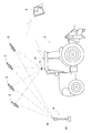
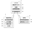
- Diagram showing schematic configuration of autonomous running system Block diagram showing schematic configuration of autonomous running system
- wireless communication terminal The figure which shows the disclaimer screen which is displayed on the display section of the wireless communication terminal
- wireless communication terminal The figure which shows the top screen displayed on the display part of a radio
- wireless communication terminal The figure which shows the path
- wireless communication terminal The figure which shows the work preparation screen displayed on the display part of a radio
- wireless communication terminal The figure which shows the work screen displayed on the display part of a radio
- wireless communication terminal The figure which shows the notification information screen displayed on the display part of a radio
- wireless communication terminal The figure which shows the work screen displayed on the display part of a radio
- the autonomous traveling system includes a tractor 1 as an autonomous traveling work vehicle that autonomously travels along a predetermined traveling route, and wireless communication that can instruct various information to the tractor 1.
- a terminal 2 (corresponding to a wireless communication device) is provided.
- a reference station 4 for acquiring position information of the tractor 1 is provided.
- the tractor 1 is illustrated as an autonomous traveling work vehicle.
- a walking work vehicle can be applied in addition to a riding work vehicle such as a rice transplanter, a combiner, a civil engineering / architecture work device, a snowplow, and the like. is there.
- the tractor 1 includes a vehicle-side wireless communication unit 14, the wireless communication terminal 2 includes a terminal-side wireless communication unit 21 (corresponding to a wireless communication unit), and the reference station 4 includes a reference station.
- a side wireless communication unit 41 is provided.
- Various types of information can be transmitted and received between the tractor 1 and the wireless communication terminal 2 by wireless communication between the vehicle-side wireless communication unit 14 and the terminal-side wireless communication unit 21, and the vehicle-side wireless communication unit 14 and the reference station
- Various types of information can be transmitted and received between the tractor 1 and the reference station 4 by wireless communication with the side wireless communication unit 41.
- the wireless communication terminal 2 and the reference station 4 are configured to transmit and receive various types of information via the tractor 1.
- the wireless communication terminal 2 and the reference station 4 are configured to be capable of directly transmitting and receiving various types of information without going through the tractor 1 by wireless communication between the terminal-side wireless communication unit 21 and the reference station-side wireless communication unit 41. You can also.
- the frequency band used for wireless communication between the wireless communication units may be a common frequency band or different frequency bands.
- the tractor 1 includes a positioning antenna 11, a control unit 12, a position information acquisition unit 13, a vehicle-side wireless communication unit 14, and the like, and the position information acquisition unit 13 is controlled by the control unit 12.
- the vehicle is configured to be able to autonomously travel while acquiring its current position information (current position of the tractor 1).
- the positioning antenna 11 is configured to receive, for example, a signal from a positioning satellite 3 constituting a satellite positioning system (GNSS).
- GNSS satellite positioning system
- the positioning antenna 11 is disposed, for example, on the upper surface of the cabin roof of the tractor 1.
- a reference station 4 installed at a predetermined reference point is provided, and satellite positioning information of the tractor 1 (mobile station) is obtained from correction information from the reference station 4. Is corrected, and a positioning method for obtaining the current position of the tractor 1 can be applied.
- various positioning methods such as DGPS (differential GPS positioning) and RTK positioning (real-time kinematic positioning) can be applied.
- DGPS differential GPS positioning
- RTK positioning real-time kinematic positioning
- the reference station 4 is provided in addition to the positioning antenna 11 provided in the tractor 1 on the mobile station side. It has been.
- the position information of the reference point that is the installation position of the reference station 4 is set and grasped in advance.
- the reference station 4 is disposed at a position (reference point) that does not interfere with the traveling of the tractor 1, for example, around the field.
- the reference station 4 includes a reference station side wireless communication unit 41 and a reference station positioning antenna 42.
- the carrier phase (satellite positioning information) from the positioning satellite 3 is measured by both the reference station 4 installed at the reference point and the positioning antenna 11 of the tractor 1 on the mobile station side whose position information is to be obtained. is doing.
- the reference station 4 generates correction information including the measured satellite positioning information and reference point position information every time the satellite positioning information is measured from the positioning satellite 3 or every time the set cycle elapses, and the reference station side wireless communication is performed.
- the correction information is transmitted from the unit 41 to the vehicle-side wireless communication unit 14 of the tractor 1.
- the position information acquisition unit 13 of the tractor 1 obtains the current position information of the tractor 1 by correcting the satellite positioning information measured by the positioning antenna 11 using the correction information transmitted from the reference station 4.
- the position information acquisition unit 13 obtains, for example, latitude information / longitude information as the current position information of the tractor 1.
- the wireless communication terminal 2 is composed of, for example, a tablet-type personal computer having a touch panel, and can display various information on the touch panel. Various information can also be input by operating the touch panel.
- the wireless communication terminal 2 can be used by being carried outside the tractor 1 by the user, and can also be used by being mounted on the side of the driver's seat of the tractor 1 or the like.
- the wireless communication terminal 2 includes a terminal-side wireless communication unit 21, a display control unit 22, a route generation unit 23, a display unit 24 (touch panel), and the like.
- the display control unit 22 is configured to display various screens on the display screen of the display unit 24. In the following description, when the display control unit 22 displays a predetermined screen, display on the display unit 24 is indicated unless otherwise specified.
- the route generation unit 23 is configured to generate a travel route on which the tractor 1 travels autonomously. Further, the wireless communication terminal 2 is provided with a storage unit (not shown), and various information such as information registered by the user is stored in the storage unit.
- the route generation unit 23 When autonomously traveling the tractor 1, first, when the user operates the wireless communication terminal 2, the route generation unit 23 generates a travel route, and various other information such as information on the generated travel route. Is transmitted from the wireless communication terminal 2 to the tractor 1. Then, after various conditions for starting autonomous traveling of the tractor 1 are satisfied, the user operates the wireless communication terminal 2 to instruct the tractor 1 to start autonomous traveling. Autonomous driving is started. During autonomous traveling, the control unit 12 of the tractor 1 acquires the current position of the tractor 1 acquired by the position information acquisition unit 13 such that the tractor 1 autonomously travels along the traveling route generated by the route generating unit 23. The operating state of the tractor 1 is controlled based on the information.
- the current position information of the tractor 1 acquired by the position information acquisition unit 13 is transmitted from the tractor 1 to the wireless communication terminal 2 in real time (for example, every several seconds), and is displayed on the display unit 24 of the wireless communication terminal 2.
- the current position of the tractor 1 can be displayed.
- the display control unit 22 displays a splash screen (corresponding to the first screen) shown in FIG. 3 and a disclaimer screen (second screen shown in FIG. 4). And the top screen (corresponding to the third screen) shown in FIG.
- the splash screen shown in FIG. 3 is a screen that is displayed at the beginning after the power is turned on or the application is started, and a company logo, a company name, and the like are displayed at the center of the screen, and an operation unit 51 (FIG. 3) that can be selected and operated by the user. 4 to 13) are not displayed.
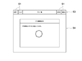
- the display control unit 22 makes a transition from the splash screen (FIG. 3) to the disclaimer screen (FIG. 4) when a certain period of time has elapsed after the power is turned on. On the disclaimer screen shown in FIG. 4, disclaimers regarding the use of the tractor 1 are displayed.
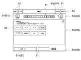
- the disclaimer screen shown in FIG. 4 is divided into an upper display region 53 on the upper end side of the screen and a lower display region 54 on the lower side of the screen.
- the upper display region 53 is displayed after this disclaimer screen.
- the various display screens (FIGS. 5 to 13) are common display screens.
- the upper display area 53 is a fixed display area whose display contents are not changed.
- the lower display area 54 is a non-fixed display area in which different display contents are displayed when the user selects and operates the operation unit 51.
- the “to map” and “help” operation sections 51 are displayed at the left end, the “GNSS” and “MENU” operation sections 51 are displayed at the right end, and the current display is displayed at the center.
- the display contents as to whether or not such a screen is displayed are displayed.
- the “to map” operation unit 51 is an operation unit for displaying map information
- the “GNSS” operation unit 51 is a satellite that acquires latitude, longitude, GNSS state, and satellite positioning information. This is an operation unit for displaying detailed information of the satellite positioning system such as the number of 3, the serial number of the reference station 4, and the remaining battery level of the base station 4.
- the route generation unit 23 generates a travel route.
- the initial registration screen shown in FIG. 5 is a screen for registering various types of information related to the tractor 1, such as the model of the tractor 1, and various types of information related to the tractor 1 are registered by user operations.
- the frame of the selected model is surrounded by a red thick line so that it can be recognized which model is selected.
- the display control unit 22 makes a transition from the initial registration screen shown in FIG. 5 to the top screen shown in FIG. Before the transition from the initial registration screen shown in FIG. 5 to the top screen shown in FIG. 6, a screen such as an initial registration screen (for example, home address registration) other than information related to the tractor 1 may be passed.
- an initial registration screen for example, home address registration
- the display control unit 22 does not display the initial registration screen shown in FIG. 5 from the disclaimer screen shown in FIG. Transition to the top screen shown.
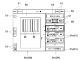
- a plurality of operation units 51 (various icons in the figure) and map information 52 that can be selected by the user are displayed, and one operation unit 51 among the plurality of operation units 51 is selected.
- the screen transitions to another screen.
- the map information 52 is displayed at the center of the lower display area 54 so as to include the registered farm fields H1 to H7.
- the center of the map information 52 is displayed at a predetermined position set in advance.
- an operation section 51a for displaying the farm field list (icon indicated by “ ⁇ ” in the figure) and an operation section 51b for the previous work (indicated by “Start work on the path worked last time” in the figure).
- other operation units 51 are displayed so as to surround the periphery of the map information 52 except for the upper part.
- the display control unit 22 displays the map information 52 so that the center of the map information 52 is the same as the center of the previous display screen. In addition, when the “current position” operation unit 51 is operated, the display control unit 22 displays the map information 52 so that the center of the map information 52 is the current position of the tractor 1.
- the display control unit 22 displays the previous work position information 55 related to the position of the tractor 1 when the tractor 1 autonomously travels the previous time in an identifiable manner.
- the previous work position information 55 is indicated by a predetermined mark (pin), and is displayed at the center of the farm field H2 where the tractor 1 autonomously traveled last time.
- the position where the previous work position 55 is displayed may be any position where the field H can be identified. For example, the work start position when the work for registering the field H is performed or the tractor 1 to the field H. It is also possible to display the previous work position 55 at the entrance.
- the display control unit 22 not only finishes the previous autonomous traveling by completing the work in the field, but also ends the previous autonomous traveling in the middle of the field work at the center of the field.
- the work position information 55 is displayed.
- the display control unit 22 starts from the top screen shown in FIG. Transition to the field list screen.
- the lower display area 54 is divided into a lower left display area 54a and a lower right display area 54b, and the lower display area of the top screen shown in FIG.
- a plurality of operation units 51 and map information 52 displayed in 54 are displayed.
- the part 51c (in the figure, an icon of “display path list of this field”) is displayed.
- the operation units 51 such as “distance order”, “name order”, and “registration order” are selected and operated, so that the fields can be rearranged in the operated order.
- the field information in the field As the field information in the field, the distance from the current position of the tractor 1 to the field, the registration date when the field information is registered, the field position information, and the like are displayed. Further, when displaying the field information list 56, the previous field information 57 (pin) indicated by a predetermined mark is displayed for the field in which the tractor 1 autonomously traveled last time. Thereby, the user can recognize on the map (previous work position information 55) from the map information 52 which farm field the tractor 1 has autonomously traveled last time, and from the field information list 56. Information about the field (previous field information 57) can also be recognized.
- the display control unit 22 changes the color of the selected field frame and surrounds it with a thick line (for example, a red thick line).
- a thick line for example, a red thick line
- the selected field is displayed so as to be distinguishable from other fields, and the selected operation unit 51 is also surrounded by a thick line by changing its frame color (for example, a red thick line).
- the selected operation unit 51 is displayed so as to be distinguishable from other operation units 51.
- the display control unit 22 starts from the field list screen shown in FIG. Transition to the path list screen.
- an enlarged screen 58 of the selected field is displayed in the lower left display area 54a, and a list 59 of previously generated path information (information on travel routes) is displayed in the lower right display area 54b.
- a path transfer operation unit 51d for transferring the selected path information (information relating to the travel route) to the tractor 1 (in the figure, an icon indicated by “Start work on this path”) is displayed. .
- the farmland enlargement screen 58 displays the travel route 25 generated by the route generation unit 23.
- a plurality of linear travel routes 25 are arranged at intervals in the left-right direction. Is displayed.
- the operation unit 51 such as “distance order”, “name order”, and “registration order” is selected and operated, so that it can be rearranged in the operated order and displayed.
- the path information the distance from the current position of the tractor 1 to the start position of the path, the date when the path is generated, the start position information of the path, and the like are displayed.
- a path detail display operation unit 51e (icon indicated by “detail” in the drawing) for displaying detailed information of the path information is displayed, and the selected path information and The selected operation unit 51 is displayed so as to be distinguishable from other path information and the other operation unit 51 by changing the color of the frame and surrounding it with a thick line (for example, surrounding it with a red thick line). .
- the display control unit 22 When the user selects and operates the path detail display operation unit 51e in a state where a specific path is selected on the path list screen illustrated in FIG. 8, the display control unit 22 performs the path illustrated in FIG. 9 from the path list screen illustrated in FIG. Transition to the detail screen.
- the display details are changed only in the lower right display area 54b from the path list screen shown in FIG.
- the detailed path information 60 the field area, the presence / absence of obstacles, the width of a non-work area (such as a headland) around the work area for generating the path (travel path), and base station information at the time of generating the path (travel path)
- the base station information with which the tractor 1 is currently communicating, the tractor information, the information on the work equipment attached to the tractor 1, the number of paths (traveling routes), and the like are displayed.
- the display control unit 22 displays the path list screen shown in FIG. 8 or the path details shown in FIG. A transition is made from the screen to the work preparation screen shown in FIG. At this time, the path information (information on the travel route) is transferred from the wireless communication terminal 2 to the tractor 1 by the terminal-side wireless communication unit 21 and the vehicle-side wireless communication unit 14.
- control unit (not shown) of the wireless communication terminal 2 and the control unit 12 of the tractor 1 are configured such that the path information transmitted via the terminal-side wireless communication unit 21 and the vehicle-side wireless communication unit 14 and the terminal-side wireless communication unit 21 and a wireless communication check process for checking whether or not the path information acquired by the tractor 1 matches via the vehicle-side wireless communication unit 14.
- this wireless communication check process for example, the total amount of path information transmitted via the terminal-side wireless communication unit 21 and the vehicle-side wireless communication unit 14, and the terminal-side wireless communication unit 21 and the vehicle-side wireless communication unit 14 Depending on whether or not the total amount of path information acquired by the tractor 1 matches, a process (CRC check process) for checking whether or not the path information matches can be applied.
- CRC check process for example, individual ID information in the path information is transferred, and whether or not the path information matches depending on whether or not the ID information matches. It is also possible to check, and various wireless communication check processes can be applied.
- the display control unit 22 includes the path information transmitted via the terminal-side wireless communication unit 21 and the vehicle-side wireless communication unit 14, and the path acquired by the tractor 1 via the terminal-side wireless communication unit 21 and the vehicle-side wireless communication unit 14. After confirming that the information matches, the operation preparation screen shown in FIG. 10 is changed to the operation screen shown in FIG. Thus, when the path information is transmitted to the tractor 1 via the terminal-side wireless communication unit 21 and the vehicle-side wireless communication unit 14, the display control unit 22 acquires the path information transmitted from the wireless communication terminal 2 and the tractor 1.
- the work screen shown in FIG. 11 can be displayed only after a predetermined condition that the path information matches is established.
- the display control unit 22 does not display the work screen shown in FIG. Is displayed, or the screen is returned to the path list screen shown in FIG.
- any error screen may be used as long as it can display the contents of the error in an identifiable manner.
- the display content may be different depending on the content of the error, or the display content may be displayed regardless of the content of the error.
- the common display screen can be the same. Incidentally, when an error screen is displayed, it is possible to return to the path list screen shown in FIG. 8 from the error screen.
- the lower display area 54 has a lower upper display area 54 c located on the upper end side, a lower lower display area 54 d located on the lower end side, a lower upper display area 54 c, and a lower part in the vertical direction.
- the display area is divided into three display areas including a lower intermediate display area 54e located between the lower display area 54d and the lower display area 54d.
- the lower upper display area 54c and the lower lower display area 54d cannot be switched to another screen, and the lower middle display area 54e can be switched to another screen.
- the lower intermediate display area 54e has the same display screen as the field expansion screen 58 and the plurality of operation units 51 displayed in the lower left display area 54a in the path list screen shown in FIG. 8 or the path detail screen shown in FIG. Is displayed.
- the display control unit 22 displays the current position 26 of the tractor 1 on the field expansion screen 58 so that the current position of the tractor 1 can be recognized. Then, the display control unit 22 can identify the travel route 25 on which the tractor 1 is currently autonomously traveling and the travel route 25 that is scheduled to travel next by changing the color and the like on the enlarged field screen 58 of the field. It can also be displayed. In addition, the display control unit 22 can display the plurality of travel routes 25 in different forms by changing the color between the travel route 25 that has already been operated and the travel route 25 that has not yet been performed.
- the display control unit 22 is configured to be able to switch the display screen of the lower intermediate display area 54e to a tractor information screen and a work command screen separately from the field enlargement screen 58.
- a tractor information screen information indicating the state of the tractor 1 such as the actual vehicle speed, the actual engine speed, and the load factor is displayed.
- an operation unit 51 and the like for changing the vehicle speed and the engine rotation speed are displayed.
- the display control unit 22 is configured to be capable of interrupting and displaying a caution screen, a warning screen, or the like as a display screen of the lower intermediate display area 54e.
- the caution screen is a screen for displaying a condition that is not satisfied among various conditions for starting self-running driving, and the warning screen is for maintaining the current driving during autonomous driving. It is a screen for displaying the cause when autonomous driving is stopped at. Since the control information related to the caution screen and the warning screen is generated by the control unit 12 of the tractor 1, the wireless communication terminal 2 receives the generated control information by the terminal-side wireless communication unit 21, The display control unit 22 interrupts and displays a caution screen or a warning screen.
- a start operation unit 51f capable of instructing the start of autonomous travel is disposed at the left end
- a stop operation unit 51g capable of instructing the stop of autonomous travel is disposed at the right end.
- the deviation information display part 61 which shows the deviation of the position of the tractor 1 with respect to the driving
- a notification information operation unit 51h for confirming error notification information and other operation units 51 are arranged, and the work progress rate by the autonomous traveling, the remaining work time, and the like are displayed. ing.
- the display control unit 22 sets the start operation unit 51f in an inactive state in which selection operation cannot be performed until various conditions for starting autonomous traveling are satisfied, and when various conditions for starting autonomous traveling are satisfied, a start operation is performed.
- the unit 51f is in an active state that allows selection operation.
- the state can be identified by the user.
- the display control unit 22 causes the start operation unit 51f to instruct the suspension of autonomous traveling temporarily. Part (not shown).
- the display control unit 22 changes the start operation unit 51f from the pause operation unit to the original display form, and the start operation unit 51f instructs the start of autonomous running. It is configured to be switchable between a display form and a display form instructing a temporary stop of autonomous driving. In this way, the display control unit 22 can change the display form of the start operation unit 51f to allow one operation unit to function as two operation units, and autonomous driving is started or temporarily stopped. This makes it easier for the user to grasp the work status of autonomous traveling, such as whether he / she is doing.
- the terminal-side wireless communication unit 21 and the vehicle-side wireless communication unit 14 receive the current position information of the tractor 1 acquired by the position information acquisition unit 13 of the tractor 1 in real time (for example, every one minute). is doing. Thereby, the display control unit 22 acquires the current position information of the tractor 1 in real time (for example, every 1 minute).
- the terminal-side wireless communication unit 21, the display control unit 22 and the like are connected to the tractor 1. It functions as a position information acquisition unit that can acquire the position information.
- the display control unit 22 causes the deviation information display unit 61 to display in which direction and how much the current position of the tractor 1 to be acquired is shifted in the lateral width direction with respect to the travel route 25.
- the control unit 12 of the tractor 1 determines in which direction and in what direction the current position of the tractor 1 is in the width direction with respect to the travel route 25.
- Deviation information is obtained, and the obtained deviation information is transmitted from the tractor 1 to the wireless communication terminal 2.
- the display control unit 22 controls the deviation information display unit 61 based on the deviation information transmitted from the tractor 1.
- the deviation information display unit 61 is provided in a state in which a plurality of display lamp units are arranged in the left-right direction, and the plurality of display lamp units have different lighting colors depending on the installation area in the left-right direction. For example, three display lamp portions located in the central region are green, two display lamp portions located in the region closer to the end are yellow, and two display lamp portions located in the region closer to the end. Is orange, and the two indicator lamps located in the most end region are red.
- the display control unit 22 controls the deviation information display unit 61 so as to display in which direction the current position of the center of the tractor 1 is shifted from the center of the travel route 25 in the width direction of the travel route 25.
- the display lamp portion located in the end region is changed from the display lamp portion located in the central region.
- the deviation information display unit 61 is controlled so that the lighting range is sequentially expanded.
- the three display lamp units located in the central region are turned on.
- the display lamp portion located in the left region adjacent thereto is also lit, and in the lateral width direction of the travel route 25 from the center of the travel route 25 to the current position of the center of the tractor 1 As the distance increases, the lighting range extends to the left.
- the display control unit 22 indicates in which direction and how much the current position of the tractor 1 to be acquired is shifted in the lateral direction of the travel path 25 before starting the autonomous traveling of the tractor 1 and during the autonomous traveling of the tractor 1.
- the deviation information display unit 61 displays the deviation information. Thereby, before starting an autonomous driving
- a distance display unit 62 for displaying the distance is arranged.
- the distance display section 62 is a bar-shaped display section extending in the vertical direction, and the length from the lower end to the upper end corresponds to the entire length of the travel route 25.
- the display control unit 22 causes the distance display unit 62 to turn on and display in a predetermined color from the lower end to the position corresponding to the current position of the tractor 1, so that the user can reach the end (headland) of the travel route 25. It is possible to recognize the distance.
- the notification information operation unit 51h (the icon indicated by “Details” in the figure) is arranged at the left end of the lower lower display area 54d. If various conditions for starting one autonomous running are satisfied, the left side of the notification information operation unit 51h is lit in a specific color for establishment (for example, green). On the contrary, if various conditions for starting autonomous traveling of the tractor 1 are not satisfied, the left side of the notification information operation unit 51h is lit in a specific color (for example, red) that is not yet established.
- the display control unit 22 A transition is made from the work screen shown in FIG. 11 to the notification information screen shown in FIG.
- the display content of the lower intermediate display area 54e is changed on the work screen shown in FIG. 11, and various conditions for starting the autonomous traveling of the tractor 1 (steering, reverser, brake , Clutch, parking brake, auxiliary transmission, vehicle speed, UFO setting) is displayed.
- the display control unit 22 lights a specific color for establishment (for example, green) for a part that satisfies the condition for each part, and indicates that the part that does not satisfy the condition is not established. Specific color (for example, red) is lit.
- the deviation information display unit 61 shows the deviation of the position of the tractor 1 with respect to the travel route 25.
- the work screens shown in FIGS. As described above, the farm field enlargement screen 58 shows the deviation of the position of the tractor 1 relative to the travel route 25.
- the display control unit 22 displays the travel route 25 and the current position 26 of the tractor 1 on the field expansion screen 58.
- the travel route 25 and the current position 26 of the tractor 1 are displayed between the start operation unit 51f and the stop operation unit 51g. 26 functions as a deviation information display unit.
- the user can easily recognize how much the current position of the tractor 1 is shifted in which direction in the lateral width direction of the travel route 25. be able to.
- Two deviation information display sections with respect to the current position 26 are arranged.
- the display control unit 22 displays the travel route 25 and the current position 26 of the tractor 1 on the field expansion screen 58 not only before the start of the autonomous travel but also during the autonomous travel. Yes.
- the user recognizes how much the tractor 1 is displaced in the lateral direction with respect to the travel route 25 not only when performing alignment for moving the tractor 1 to the autonomous travel start position but also during autonomous travel. can do.
- the current position 26 of the tractor 1 indicated by a dotted line indicates a state where the current position 26 deviates to the right side or the left side with respect to the travel route 25.
- the display control unit 22 controls the display screen of the display unit 24 and the tractor 1 is autonomously operated to perform work on the field, the user selects and operates the operation unit 51 on each display screen.
- the display control unit 22 performs control so that the display screen sequentially changes as in the following (1) to (8).
- the registration work on the initial registration screen shown in FIG. 5 is initially performed only once.
- the display control unit 22 (2) skips the disclaimer screen shown in FIG. 4 and (3I) skips the initial registration screen shown in FIG. 5 and (4) transitions to the top screen shown in FIG. I am letting.
- the above (1) to (8) show the case where work is performed by transmitting path information (information on the travel route 25) from the wireless communication terminal 2 to the tractor 1. For example, new path information is transmitted. Instead, the work can be performed using the past path information (information relating to the travel route 25) previously transmitted to the tractor 1.
- the display control unit 22 controls the display screen to sequentially change as in (1) to (4).
- (4) On the top screen shown in FIG. 51b (corresponding to the rework operation unit) is selected and operated.
- the display control unit 22 (4) from the top screen shown in FIG. 6, (5) the field list screen shown in FIG. 7, and (6) the path list screen shown in FIG. (7)
- the screen is shifted to the work preparation screen shown in FIG.
- the display control unit 22 performs wireless communication without transmitting past path information (information on the travel route 25) to the tractor 1, unlike when the display screens (4) to (7) are sequentially shifted.
- a wireless communication check process is performed between the control unit (not shown) of the terminal 2 and the control unit 12 of the tractor 1.
- the control unit 12 of the tractor 1 since the control unit 12 of the tractor 1 has acquired the past path information transmitted previously, the control unit 12 of the wireless communication terminal 2 (illustrated) is transmitted from the control unit 12 of the tractor 1. Is omitted) by asking whether or not the acquired past path information matches the past path information previously transmitted from the wireless communication terminal 2 to the tractor 1. Then, for example, the past path information matches depending on whether or not the total amount of acquired past path information matches the total amount of past path information previously transmitted from the wireless communication terminal 2 to the tractor 1. It is possible to perform a process for checking whether or not (CRC check process). Further, instead of the CRC check process, for example, individual ID information in the past path information is transferred, and whether or not the past path information matches is checked by whether or not the ID information matches. In addition, various wireless communication check processes can be applied.
- CRC check process for example, individual ID information in the past path information is transferred, and whether or not the past path information matches is checked by whether or not the ID information matches.
- various wireless communication check processes can be applied
- the display control unit 22 displays the work preparation screen (7) shown in FIG. 10 and performs wireless communication check processing.
- the work screen shown in FIG. 11 can be displayed only after the predetermined condition that the past path information matches is established.
- the display control unit 22 displays an error screen without displaying the work screen shown in FIG. 11, or displays the error screen on the path list screen shown in FIG. I try to return it.
- any error screen may be used as long as it can display the contents of the error in an identifiable manner.
- the display contents may be different depending on the contents of the error,
- the common display screen can be the same. Incidentally, when an error screen is displayed, it is possible to return to the path list screen shown in FIG. 8 from the error screen.
- the display control unit 22 displays (8) the same display screen as the work preparation screen shown in FIG. 10 before (8) the work screen shown in FIG. 11 is displayed. I am letting. Thereby, the user can easily recognize that (8) the work screen shown in FIG. 11 is displayed next when the work preparation screen shown in (7) FIG. 10 is displayed.
- the display control unit 22 displays the disclaimer screen shown in FIG. 4 next to the splash screen shown in FIG. 3.
- the display control unit 22 has changed to the work screen shown in FIG. 11.
- the disclaimer screen shown in FIG. 4 can be displayed, and the timing for displaying the disclaimer screen shown in FIG. 4 can be changed as appropriate.
- the disclaimer screen shown in FIG. 4 can be displayed after the start operation unit 51f is selected on the work screen shown in FIG. In this case, for example, the start operation unit 51f can be omitted from the work screen shown in FIG. 11, and the start operation unit 51f can be added to the disclaimer screen shown in FIG.
- the tractor 1 is provided with an imaging device such as a camera, and a captured image of the imaging device can be displayed on the display unit 24 of the wireless communication terminal 2.
- the captured image of the imaging device can be fixedly displayed so that it is always displayed.
- the work screens shown in FIGS. 11 and 13 function as the deviation information display unit 61 arranged in the lower upper display region 54c and the deviation information display unit arranged in the lower intermediate display region 54e.
- route 25 and the present position 26 of the tractor 1 was shown, only either one deviation information display part can also be arrange
- the present invention can be applied to various wireless communication devices capable of transmitting and receiving information related to autonomous driving.
Landscapes
- Engineering & Computer Science (AREA)
- Radar, Positioning & Navigation (AREA)
- Remote Sensing (AREA)
- Aviation & Aerospace Engineering (AREA)
- Physics & Mathematics (AREA)
- General Physics & Mathematics (AREA)
- Automation & Control Theory (AREA)
- Signal Processing (AREA)
- Computer Networks & Wireless Communication (AREA)
- Control Of Position, Course, Altitude, Or Attitude Of Moving Bodies (AREA)
- Guiding Agricultural Machines (AREA)
- Business, Economics & Management (AREA)
- Health & Medical Sciences (AREA)
- Artificial Intelligence (AREA)
- Evolutionary Computation (AREA)
- Game Theory and Decision Science (AREA)
- Medical Informatics (AREA)
- General Engineering & Computer Science (AREA)
Abstract
Description
表示部に表示する画面を制御する表示制御部とを備え、
前記表示制御部は、電源投入後又はアプリケーション起動後に、ユーザが選択可能な操作部が表示されていない状態で、一定期間経過後に表示が終了する第1画面と、前記自律走行作業車両の使用に関する免責事項を表示する第2画面と、ユーザが選択可能な複数の操作部及び地図情報が表示され、それら複数の操作部の内、一つの操作部が選択されることで他の画面に遷移する第3画面とを順次表示させることを特徴とする点にある。
前記表示制御部は、前記第3画面において地図情報を表示させる際に、前回、前記自律走行作業車両が自律走行を行ったときの前記自律走行作業車両の位置に関する前回作業位置情報を識別可能に表示させることを特徴とする点にある。
前記表示制御部は、前記自律走行作業車両の自律走行の開始前に、前記走行経路を含めた作業画面を表示させるものであり、
その作業画面において、左右一端部に自律走行の開始を指示可能な開始操作部が配置されているとともに、左右他端部に自律走行の停止を指示可能な停止操作部が配置され、且つ、前記開始操作部と前記停止操作部との間には前記走行経路に対する前記自律走行作業車両の位置の偏差を示す偏差情報表示部が配置されていることを特徴とする点にある。
前記所定条件は、前記無線通信部を介して送信した前記走行経路に関する情報と、前記無線通信部を介して前記自律走行作業車両が取得した前記走行経路に関する情報とが一致することが含まれていることを特徴とする点にある。
前記表示制御部は、前記再作業操作部が選択された場合、前記過去の走行経路に関する情報を前記自律走行作業車両に送信することなく、前記所定条件が成立した場合に、前記作業画面を前記表示部に表示させることを特徴とする点にある。
この自律走行システムは、図1に示すように、予め定められた走行経路に沿って自律走行する自律走行作業車両としてのトラクタ1と、そのトラクタ1に対して各種の情報を指示可能な無線通信端末2(無線通信装置に相当する)とが備えられている。そして、この実施形態では、トラクタ1の位置情報を取得するための基準局4が備えられている。
(2)図4に示す免責事項画面
(3)図5に示す初期登録画面
(4)図6に示すトップ画面
(5)図7に示す圃場リスト画面
(6)図8に示すパス一覧画面(図8に示すパス一覧画面→図9に示すパス詳細画面)
(7)図10に示す作業準備画面
(8)図11に示す作業画面
(1)上記実施形態では、表示制御部22が、図4に示す免責事項画面を、図3に示すスプラッシュ画面の次に表示させているが、例えば、図11に示す作業画面に遷移された後、図4に示す免責事項画面を表示させることもでき、図4に示す免責事項画面をどのようなタイミングで表示させるかは適宜変更が可能である。
また、図11に示す作業画面において開始操作部51fが選択操作された後に、図4に示す免責事項画面を表示させることもできる。この場合には、例えば、図11に示す作業画面において開始操作部51fを省略して、図4に示す免責事項画面に開始操作部51fを追加して表示させることができる。
2 無線通信端末(無線通信装置)
13 位置情報取得部
21 端末側無線通信部(無線通信部)
22 表示制御部
24 表示部
51 操作部
51b 前回作業用操作部(再作業操作部)
51f 開始操作部
51g 停止操作部
52 地図情報
55 前回作業位置情報
61 偏差情報表示部
Claims (6)
- 予め定められた走行経路に沿って自律走行する自律走行作業車両と無線通信可能な無線通信部と、
表示部に表示する画面を制御する表示制御部とを備え、
前記表示制御部は、電源投入後又はアプリケーション起動後に、ユーザが選択可能な操作部が表示されていない状態で、一定期間経過後に表示が終了する第1画面と、前記自律走行作業車両の使用に関する免責事項を表示する第2画面と、ユーザが選択可能な複数の操作部及び地図情報が表示され、それら複数の操作部の内、一つの操作部が選択されることで他の画面に遷移する第3画面とを順次表示させることを特徴とする無線通信装置。 - 前記自律走行作業車両の位置情報を取得する位置情報取得部を備え、
前記表示制御部は、前記第3画面において地図情報を表示させる際に、前回、前記自律走行作業車両が自律走行を行ったときの前記自律走行作業車両の位置に関する前回作業位置情報を識別可能に表示させることを特徴とする請求項1に記載の無線通信装置。 - 前記自律走行作業車両の位置情報を取得する位置情報取得部を備え、
前記表示制御部は、前記自律走行作業車両の自律走行の開始前に、前記走行経路を含めた作業画面を表示させるものであり、
その作業画面において、左右一端部に自律走行の開始を指示可能な開始操作部が配置されているとともに、左右他端部に自律走行の停止を指示可能な停止操作部が配置され、且つ、前記開始操作部と前記停止操作部との間には前記走行経路に対する前記自律走行作業車両の位置の偏差を示す偏差情報表示部が配置されていることを特徴とする請求項1又は2に記載の無線通信装置。 - 前記表示制御部は、前記無線通信部を介して前記走行経路に関する情報が前記自律走行作業車両に送信され、且つ、所定条件が成立した場合に、前記走行経路を含めた作業画面を前記表示部に表示可能であり、
前記所定条件は、前記無線通信部を介して送信した前記走行経路に関する情報と、前記無線通信部を介して前記自律走行作業車両が取得した前記走行経路に関する情報とが一致することが含まれていることを特徴とする請求項1~3の何れか1項に記載の無線通信装置。 - 前記複数の操作部には、以前に前記自律走行作業車両に送信した過去の走行経路にて作業を行う再作業操作部が含まれ、
前記表示制御部は、前記再作業操作部が選択された場合、前記過去の走行経路に関する情報を前記自律走行作業車両に送信することなく、前記所定条件が成立した場合に、前記作業画面を前記表示部に表示させることを特徴とする請求項4に記載の無線通信装置。 - 前記表示制御部は、前記走行経路に関する情報又は前記過去の走行経路に関する情報を前記自律走行作業車両に送信するか否かを問わず、前記作業画面を前記表示部に表示する前に、作業準備画面を前記表示部に表示させることを特徴とする請求項5に記載の無線通信装置。
Priority Applications (7)
| Application Number | Priority Date | Filing Date | Title |
|---|---|---|---|
| KR1020217032631A KR102460036B1 (ko) | 2017-03-03 | 2018-02-09 | 무선 통신 장치 |
| CN201880005516.1A CN110325934A (zh) | 2017-03-03 | 2018-02-09 | 无线通信装置 |
| KR1020227037024A KR102661575B1 (ko) | 2017-03-03 | 2018-02-09 | 무선 통신 장치 |
| KR1020217011438A KR20210045524A (ko) | 2017-03-03 | 2018-02-09 | 무선 통신 장치 |
| KR1020197017193A KR102243600B1 (ko) | 2017-03-03 | 2018-02-09 | 무선 통신 장치 |
| KR1020247013370A KR102773143B1 (ko) | 2017-03-03 | 2018-02-09 | 무선 통신 장치 |
| KR1020257005595A KR20250028528A (ko) | 2017-03-03 | 2018-02-09 | 무선 통신 장치 |
Applications Claiming Priority (2)
| Application Number | Priority Date | Filing Date | Title |
|---|---|---|---|
| JP2017040430A JP6739375B2 (ja) | 2017-03-03 | 2017-03-03 | 無線通信装置 |
| JP2017-040430 | 2017-03-03 |
Publications (1)
| Publication Number | Publication Date |
|---|---|
| WO2018159261A1 true WO2018159261A1 (ja) | 2018-09-07 |
Family
ID=63371035
Family Applications (1)
| Application Number | Title | Priority Date | Filing Date |
|---|---|---|---|
| PCT/JP2018/004596 Ceased WO2018159261A1 (ja) | 2017-03-03 | 2018-02-09 | 無線通信装置 |
Country Status (4)
| Country | Link |
|---|---|
| JP (4) | JP6739375B2 (ja) |
| KR (6) | KR102773143B1 (ja) |
| CN (1) | CN110325934A (ja) |
| WO (1) | WO2018159261A1 (ja) |
Families Citing this family (7)
| Publication number | Priority date | Publication date | Assignee | Title |
|---|---|---|---|---|
| JP6739375B2 (ja) * | 2017-03-03 | 2020-08-12 | ヤンマーパワーテクノロジー株式会社 | 無線通信装置 |
| US11693406B2 (en) | 2020-03-05 | 2023-07-04 | Caterpillar Paving Products Inc. | Task completion time estimation for an autonomous machine |
| AU2021414757B2 (en) | 2020-12-29 | 2026-02-05 | Kubota Corporation | Agriculture assistance system and unmanned aircraft |
| JP7413250B2 (ja) * | 2020-12-29 | 2024-01-15 | 株式会社クボタ | 農業支援システム |
| JP7745350B2 (ja) | 2021-02-16 | 2025-09-29 | ヤンマーホールディングス株式会社 | 表示方法、表示端末、及び表示プログラム |
| JP7597632B2 (ja) * | 2021-04-12 | 2024-12-10 | ヤンマーホールディングス株式会社 | 表示装置及び農作業機 |
| JP2026061306A (ja) | 2024-09-30 | 2026-04-09 | ヤンマーホールディングス株式会社 | 作業車両の制御方法、作業車両用制御プログラム、作業車両用制御システム及び作業システム |
Citations (6)
| Publication number | Priority date | Publication date | Assignee | Title |
|---|---|---|---|---|
| JP2002358122A (ja) * | 2001-05-31 | 2002-12-13 | Yanmar Agricult Equip Co Ltd | 農業用作業車 |
| JP2004008186A (ja) * | 2002-06-11 | 2004-01-15 | Yanmar Agricult Equip Co Ltd | 農業用作業車 |
| JP2014085895A (ja) * | 2012-10-24 | 2014-05-12 | Shuichi Sakagami | 住宅のライフサイクル維持コスト軽減システム |
| WO2016017367A1 (ja) * | 2014-07-30 | 2016-02-04 | ヤンマー株式会社 | 遠隔操作装置 |
| JP2016093125A (ja) * | 2014-11-13 | 2016-05-26 | ヤンマー株式会社 | 走行経路設定装置 |
| JP2016224746A (ja) * | 2015-06-01 | 2016-12-28 | 株式会社イトーキ | パフォーマンスレベル測定装置、パフォーマンスレベル測定方法及びプログラム。 |
Family Cites Families (24)
| Publication number | Priority date | Publication date | Assignee | Title |
|---|---|---|---|---|
| JPH10234204A (ja) * | 1997-02-28 | 1998-09-08 | Kubota Corp | 走行用アシスト装置 |
| US6396516B1 (en) * | 1998-05-29 | 2002-05-28 | Plexus Systems, Llc | Graphical user interface shop floor control system |
| JP2002085305A (ja) * | 2000-09-12 | 2002-03-26 | Toshiba Tec Corp | ロボットクリーナ及びロボットクリーナシステム |
| JP4801252B2 (ja) | 2000-12-19 | 2011-10-26 | ヤンマー株式会社 | 農業用作業車 |
| US7394403B2 (en) * | 2002-02-14 | 2008-07-01 | Everyday Wireless, Llc | Everyday wireless vehicle notification and vehicle location systems and methods related thereto |
| JP2004110109A (ja) * | 2002-09-13 | 2004-04-08 | Nippon Yusoki Co Ltd | 無人搬送システムの異常復旧制御装置及び制御方法 |
| KR20060118234A (ko) * | 2005-05-16 | 2006-11-23 | 엘지전자 주식회사 | 네비게이션 시스템의 요약경로 안내방법 |
| JP4948098B2 (ja) * | 2006-09-12 | 2012-06-06 | ヤンマー株式会社 | 農用作業車 |
| JP5016409B2 (ja) * | 2007-07-26 | 2012-09-05 | パナソニック株式会社 | 自律移動装置 |
| WO2011074672A1 (ja) * | 2009-12-18 | 2011-06-23 | 株式会社小松製作所 | 作業車両のモニタ装置 |
| US8626407B2 (en) * | 2011-07-26 | 2014-01-07 | Kubota Corporation | Work vehicle |
| JP5994659B2 (ja) * | 2012-05-07 | 2016-09-21 | 株式会社デンソー | 車両用装置、情報表示プログラム、車両用システム |
| DE102013110909A1 (de) * | 2013-10-01 | 2015-04-02 | Scania Cv Ab | Vorrichtung zum automatischen Fahren eines Fahrzeugs |
| JP6111179B2 (ja) | 2013-10-22 | 2017-04-05 | 日立建機株式会社 | ダンプトラックの自律走行システム |
| KR101691317B1 (ko) * | 2013-11-19 | 2017-01-09 | 가부시키가이샤 고마쓰 세이사쿠쇼 | 작업 차량의 표시 장치 및 그 표시 방법 |
| EP3104245A4 (en) | 2014-02-06 | 2017-11-01 | Yanmar Co., Ltd. | Method for setting travel path of autonomous travel work vehicle |
| CN106133629B (zh) * | 2014-04-25 | 2020-04-07 | 索尼公司 | 信息处理装置、信息处理方法、程序和成像系统 |
| US9436182B2 (en) * | 2014-05-23 | 2016-09-06 | Google Inc. | Autonomous vehicles |
| JP6415880B2 (ja) * | 2014-07-17 | 2018-10-31 | 株式会社クボタ | 走行作業機及びそれに用いられる自動操舵システム |
| WO2016060178A1 (ja) * | 2014-10-16 | 2016-04-21 | ヤンマー株式会社 | 作業車両 |
| JP6253567B2 (ja) * | 2014-11-17 | 2017-12-27 | ヤンマー株式会社 | 作業車両の移動システム |
| JP6031491B2 (ja) | 2014-11-21 | 2016-11-24 | ジオサーフ株式会社 | 圃場ガイダンスシステム及び圃場ガイダンス方法並びにソフトウェア及びソフトウェアを格納した記憶媒体 |
| JP6467897B2 (ja) * | 2014-12-10 | 2019-02-13 | 井関農機株式会社 | トラクタ |
| JP6739375B2 (ja) | 2017-03-03 | 2020-08-12 | ヤンマーパワーテクノロジー株式会社 | 無線通信装置 |
-
2017
- 2017-03-03 JP JP2017040430A patent/JP6739375B2/ja active Active
-
2018
- 2018-02-09 CN CN201880005516.1A patent/CN110325934A/zh active Pending
- 2018-02-09 KR KR1020247013370A patent/KR102773143B1/ko active Active
- 2018-02-09 KR KR1020197017193A patent/KR102243600B1/ko active Active
- 2018-02-09 WO PCT/JP2018/004596 patent/WO2018159261A1/ja not_active Ceased
- 2018-02-09 KR KR1020217011438A patent/KR20210045524A/ko not_active Ceased
- 2018-02-09 KR KR1020257005595A patent/KR20250028528A/ko active Pending
- 2018-02-09 KR KR1020227037024A patent/KR102661575B1/ko active Active
- 2018-02-09 KR KR1020217032631A patent/KR102460036B1/ko active Active
-
2020
- 2020-07-20 JP JP2020123371A patent/JP7119031B2/ja active Active
-
2022
- 2022-08-03 JP JP2022123999A patent/JP7454610B2/ja active Active
-
2023
- 2023-12-08 JP JP2023207343A patent/JP2024023603A/ja active Pending
Patent Citations (6)
| Publication number | Priority date | Publication date | Assignee | Title |
|---|---|---|---|---|
| JP2002358122A (ja) * | 2001-05-31 | 2002-12-13 | Yanmar Agricult Equip Co Ltd | 農業用作業車 |
| JP2004008186A (ja) * | 2002-06-11 | 2004-01-15 | Yanmar Agricult Equip Co Ltd | 農業用作業車 |
| JP2014085895A (ja) * | 2012-10-24 | 2014-05-12 | Shuichi Sakagami | 住宅のライフサイクル維持コスト軽減システム |
| WO2016017367A1 (ja) * | 2014-07-30 | 2016-02-04 | ヤンマー株式会社 | 遠隔操作装置 |
| JP2016093125A (ja) * | 2014-11-13 | 2016-05-26 | ヤンマー株式会社 | 走行経路設定装置 |
| JP2016224746A (ja) * | 2015-06-01 | 2016-12-28 | 株式会社イトーキ | パフォーマンスレベル測定装置、パフォーマンスレベル測定方法及びプログラム。 |
Also Published As
| Publication number | Publication date |
|---|---|
| JP2020177697A (ja) | 2020-10-29 |
| KR102460036B1 (ko) | 2022-10-27 |
| JP2018147161A (ja) | 2018-09-20 |
| KR102243600B1 (ko) | 2021-04-22 |
| KR20220148938A (ko) | 2022-11-07 |
| KR102773143B1 (ko) | 2025-02-25 |
| JP7454610B2 (ja) | 2024-03-22 |
| CN110325934A (zh) | 2019-10-11 |
| KR102661575B1 (ko) | 2024-04-26 |
| JP2022159369A (ja) | 2022-10-17 |
| JP7119031B2 (ja) | 2022-08-16 |
| KR20190082914A (ko) | 2019-07-10 |
| KR20240060838A (ko) | 2024-05-08 |
| KR20210127792A (ko) | 2021-10-22 |
| KR20250028528A (ko) | 2025-02-28 |
| KR20210045524A (ko) | 2021-04-26 |
| JP6739375B2 (ja) | 2020-08-12 |
| JP2024023603A (ja) | 2024-02-21 |
Similar Documents
| Publication | Publication Date | Title |
|---|---|---|
| JP7454610B2 (ja) | 表示システム | |
| CN110352392B (zh) | 作业画面显示系统 | |
| JP2023143983A (ja) | 自動走行システムおよび表示方法 | |
| CN111448528A (zh) | 行驶路径设定装置 | |
| JP6956228B2 (ja) | 作業画面表示システム | |
| JP2018147421A (ja) | 経路生成システム | |
| EP3175693A1 (en) | Remote control apparatus | |
| JP2024169567A (ja) | 画面表示システム及び画面表示方法 |
Legal Events
| Date | Code | Title | Description |
|---|---|---|---|
| 121 | Ep: the epo has been informed by wipo that ep was designated in this application |
Ref document number: 18761085 Country of ref document: EP Kind code of ref document: A1 |
|
| DPE1 | Request for preliminary examination filed after expiration of 19th month from priority date (pct application filed from 20040101) | ||
| ENP | Entry into the national phase |
Ref document number: 20197017193 Country of ref document: KR Kind code of ref document: A |
|
| NENP | Non-entry into the national phase |
Ref country code: DE |
|
| 122 | Ep: pct application non-entry in european phase |
Ref document number: 18761085 Country of ref document: EP Kind code of ref document: A1 |
|
| WWD | Wipo information: divisional of initial pct application |
Ref document number: 1020257005595 Country of ref document: KR |
|
| WWP | Wipo information: published in national office |
Ref document number: 1020257005595 Country of ref document: KR |