WO2018155017A1 - 波長変換方法および波長変換器 - Google Patents
波長変換方法および波長変換器 Download PDFInfo
- Publication number
- WO2018155017A1 WO2018155017A1 PCT/JP2018/001295 JP2018001295W WO2018155017A1 WO 2018155017 A1 WO2018155017 A1 WO 2018155017A1 JP 2018001295 W JP2018001295 W JP 2018001295W WO 2018155017 A1 WO2018155017 A1 WO 2018155017A1
- Authority
- WO
- WIPO (PCT)
- Prior art keywords
- wavelength
- signal light
- frequency
- light
- stage
- Prior art date
- Legal status (The legal status is an assumption and is not a legal conclusion. Google has not performed a legal analysis and makes no representation as to the accuracy of the status listed.)
- Ceased
Links
Images





Classifications
-
- G—PHYSICS
- G02—OPTICS
- G02F—OPTICAL DEVICES OR ARRANGEMENTS FOR THE CONTROL OF LIGHT BY MODIFICATION OF THE OPTICAL PROPERTIES OF THE MEDIA OF THE ELEMENTS INVOLVED THEREIN; NON-LINEAR OPTICS; FREQUENCY-CHANGING OF LIGHT; OPTICAL LOGIC ELEMENTS; OPTICAL ANALOGUE/DIGITAL CONVERTERS
- G02F1/00—Devices or arrangements for the control of the intensity, colour, phase, polarisation or direction of light arriving from an independent light source, e.g. switching, gating or modulating; Non-linear optics
- G02F1/35—Non-linear optics
- G02F1/365—Non-linear optics in an optical waveguide structure
Definitions
- the present invention relates to an all-optical wavelength conversion method and all-optical wavelength converter that can be used for optical fiber communication.
- the input signal light is once converted to another wavelength by the first-stage wavelength conversion (the signal light obtained here is called the intermediate signal light), and the intermediate signal light is converted by the second-stage conversion.
- All-optical wavelength converters configured to convert to an arbitrary output wavelength within the operating band are known (Non-Patent Documents 1 to 3).
- This all-optical wavelength converter has a configuration that enables a conversion operation corresponding to an arbitrary input / output wavelength without a “guard band” meaning a wavelength band in which the wavelength conversion operation is impossible, and further, an input signal. This is the most promising because the phase of light is maintained and polarization independent operation is possible.
- the wavelength band called the C band having a wavelength range of 1530 to 1565 nm or a frequency range of 195.9 to 191.6 THz is used as an operating band, and a wavelength multiplexed signal having an arbitrary band and a center wavelength among them.
- the wavelength allocated to the intermediate signal light obtained after the first stage conversion is clearly defined to have an arbitrary band within the C band.
- a method and a wavelength converter for performing a conversion operation on an arbitrary input / output wavelength without distortion on a wavelength multiplexed signal are proposed.
- An operation band is a predetermined frequency range, and input signal light having an arbitrary wavelength (carrier optical frequency) within the operation band is held in an optical region while holding information held by the input signal light.
- the intermediate signal light is amplified by a second optical amplifier
- the intermediate signal light by the second-stage wavelength conversion by degenerate four-wave mixing generated in the second nonlinear medium by the amplified intermediate signal light and the second-stage pump light whose wavelength is set according to the wavelength.
- the maximum frequency of the input signal light is f1
- the minimum frequency is f2
- the maximum frequency of the intermediate signal light is f3
- the minimum frequency is set to a value greater than 191.2 THz, and the maximum frequency f3 of the intermediate signal light is fixed to a value equal to or less than 191.2 THz, Then, by applying a gain flattening design to the second optical amplifier in the frequency band below f3, Controlling to output the wavelength of the output signal light without distortion, A wavelength conversion method characterized by the above.
- the wavelength conversion method according to (1) The input signal light is a wavelength multiplexed signal; A wavelength conversion method characterized by the above.
- the wavelength conversion method according to any one of (1) and (3) When the minimum frequency of the operating band is fmin, fmin ⁇ f3> 2B is satisfied, A wavelength conversion method characterized by the above.
- the method according to any one of (1) and (4), The nonlinear medium is an optical fiber; A wavelength conversion method characterized by the above.
- the first-stage wavelength conversion unit and the intermediate signal light amplification unit including the second optical amplifier and the second-stage length conversion unit connected in order Become The first-stage wavelength converter and the second-stage wavelength converter are connected to the first-stage pump light generator and the second-stage pump light generator connected to the pump signal frequency dithering RF signal generator, respectively.
- the input signal light is held in the optical region while maintaining the information of the input signal light with respect to the input signal light having an arbitrary wavelength (carrier optical frequency) within the operation band as a predetermined frequency range.
- a wavelength converter that converts the wavelength of the output signal into a wavelength of any output signal light within the operating band, Amplifying the input signal light by a first optical amplifier having a gain flattening design within the operating band in an input signal light amplifier;
- the first-stage wavelength by degenerate four-wave mixing generated in the first nonlinear medium by the amplified input signal light and the first-stage pump light whose wavelength is set according to the wavelength in the first-stage wavelength conversion unit
- the intermediate signal light amplification unit amplifies the intermediate signal light by a second optical amplifier
- the amplified intermediate signal light and the second stage pump light whose wavelength is set in accordance with the wavelength of the amplified intermediate signal light are generated by degenerate four-wave mixing generated in the second nonlinear medium.
- the minimum frequency is set to a value greater than 191.2 THz, and the maximum frequency f3 of the intermediate signal light is fixed to a value equal to or less than 191.2 THz, Then, by applying a gain flattening design to the second optical amplifier in the frequency band below f3, Controlling to output the wavelength of the output signal light without distortion, A wavelength converter characterized by.
- the wavelength converter according to (1) The wavelength converter, wherein the input signal light is a wavelength multiplexed signal.
- the wavelength converter according to any one of (6) and (7) Using the low-pass filter having a cut-off frequency smaller than the minimum frequency of the first stage pump light in the intermediate signal light amplification unit, the input signal light and the first stage pump light are removed to remove the intermediate signal Allowing only light to pass through, A wavelength converter characterized by.
- the wavelength converter according to any one of (6) and (8) When the minimum frequency of the operating band is fmin, fmin ⁇ f3> 2B is satisfied, A wavelength converter characterized by.
- the nonlinear medium is an optical fiber; A wavelength converter characterized by.
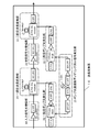
- FIG. 2 is a diagram illustrating an internal configuration of a wavelength converter 16.
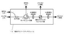
- FIG. 2 is a diagram illustrating a configuration of a polarization diversity module 12.
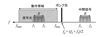
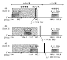
- FIG. It is the figure which showed on the frequency axis the spectrum of the signal light at the time of wavelength conversion, pump light, and intermediate
- 4 (a), 4 (b), and 4 (c) representing the present invention correspond to the case where the frequency of the signal light is set to the general condition, the lowest frequency side and the highest frequency side, respectively.
- 4D shows, as a comparative example of the present invention, the spectrum at the time of wavelength conversion for the signal light whose band is B when the maximum frequency f3 of the intermediate signal light is set to 191.6 THz in the C band. This is shown on the axis. It is the schematic diagram which showed the mode of the wavelength conversion by a single pump light on the frequency axis by using the WDM signal of the zone
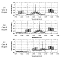
- the measurement result of the optical spectrum output from the polarization diversity module of the second-stage wavelength converter when the frequency arrangement of the input signal light is Case 2 and the frequency arrangement of the output signal light is Case 1, 2, 3 FIG.
- the measurement result of the optical spectrum output from the polarization diversity module of the second-stage wavelength converter when the frequency arrangement of the input signal light is Case 3 and the frequency arrangement of the output signal light is Case 1, 2, 3 FIG.
- BER bit error rate
- FIG. 1 is a diagram illustrating the internal configuration of the wavelength converter.
- the input signal light has a center wavelength (carrier optical frequency) within a certain operating band, and when this is input to the wavelength converter, the input signal light amplifying unit 19, the first-stage wavelength converting unit 20, the intermediate signal Through the optical amplifying unit 21 and the second-stage wavelength converting unit 22, the center wavelength (carrier optical frequency) is converted into an arbitrary value within the operation band and output.
- the center wavelength carrier optical frequency
- the input signal light amplifier and the intermediate signal light amplifier are composed of an optical amplifier and an optical filter. Although not shown in FIG. 1, an optical amplifier and an optical filter may also be provided as an output signal light amplification unit after the second-stage wavelength conversion unit. On the other hand, when the input signal light has a necessary and sufficient optical power, the wavelength converter does not have to include the input signal light amplification unit, and the input signal light is directly input to the first-stage wavelength conversion unit. There may be.
- the first-stage and second-stage wavelength converters include a polarization diversity module 12, a polarization-maintaining highly nonlinear fiber 11 (PM-HNLF) connected thereto, and an optical filter 4. Is a wavelength-variable and high-power continuous light generated by the first-stage and second-stage pump light generators, respectively, as pump light.
- PM-HNLF polarization-maintaining highly nonlinear fiber 11
- degenerate FWM occurs due to single pump light, and the input signal light is converted as intermediate signal light having a wavelength outside the operating band by the first-stage wavelength conversion, and then the second-stage wavelength conversion.
- the intermediate signal light is converted into output signal light having a certain wavelength within the operating band by wavelength conversion.
- a variable wavelength conversion operation corresponding to any combination of input and output wavelengths can be performed within the operation band.
- FIG. 1 the use of an optical fiber having polarization maintaining characteristics and high nonlinearity as a nonlinear medium for generating FWM and based on quartz glass as a material is considered.
- a waveguide device made of silicon, an optical fiber using chalcogenide glass, a waveguide device, or a semiconductor optical amplifier (SOA) can also be used.
- the PM-HNLF is the best nonlinear medium from the viewpoint of polarization maintaining characteristics, cumulative nonlinear effect, insertion loss, connectivity with other optical fibers, and the like.
- polarization diversity module 12 having the configuration shown in FIG. 2, a polarization-independent wavelength conversion operation in which the operation of the FWM does not depend on the polarization plane (polarization plane) of the input signal light is possible.
- the wavelength (frequency) of the pump light is phase-modulated to suppress stimulated Brillouin scattering (SBS) caused in the optical fiber by the high-power pump light (this is dithered).
- the optical phase modulator 7 is used in the pump light generation units 23 and 24 of each stage, and the frequency generated by the RF signal generation unit 25 for pump optical frequency dithering is an RF having a frequency of about 300 MHz. A signal is applied.
- the RF signal is bifurcated, the intensity difference and relative phase of each are adjusted, and the phase modulation for the first-stage and second-stage pump lights is synchronized, so that the phase modulation added to the output signal light through the FWM "Counter dither" that cancels the effect of can be enabled.
- the operation is performed, and various frequency settings necessary for this purpose will be described below.
- FIG. 3 shows the spectrum of the signal light, the pump light, and the intermediate signal light at the time of wavelength conversion on the frequency axis.
- the operation band covers the C band. .
- the signal light means output signal light, and is converted from intermediate signal light to output signal light. Since the wavelength conversion considered here is based on degenerate FWM, the signal light of frequency f1 and the intermediate signal light of f4 correspond before and after wavelength conversion, and the signal light of f2 and the intermediate signal light of f3 correspond. Thus, the corresponding signal lights before and after wavelength conversion are in a phase conjugate relationship.
- the intermediate signal light may exist in the C band.
- the frequency of the intermediate signal light is set flexibly so that the operation is not hindered.
- the frequency band of the intermediate signal light is not limited to the C band and the frequency is f ⁇ 191.6 THz, depending on the center frequency and bandwidth conditions of the input signal light.
- the L band band is reached.
- FIG. 4A is a diagram corresponding to a general condition regarding the frequency setting of the signal light.
- FIGS. 4B and 4C show that the frequency of the signal light is set to the lowest frequency side and the high frequency side, respectively.
- the maximum frequency f3 of the intermediate signal light is fixed at 191.2 THz.
- the input / output signal light is always present in the C band and the intermediate signal light is always present in the L band where f ⁇ 191.2 THz. Therefore, as EDFA1 and EDFA2 in FIG.
- an optical amplifier with a gain flattening design for the L band it is possible to amplify a WDM signal with a flat gain for each channel during wavelength conversion operation.
- wavelength conversion operation for any input / output wavelength without distortion on the frequency axis is possible for the first time.
- the value of the maximum frequency f3 of the intermediate signal light does not need to be 191.2 THz, and may be a value of 191.2 THz or less in the L band.
- the gain flattening design is not necessarily made as the optical amplifier, distortion on the frequency axis is allowed by using an optical amplifier designed for C and L bands and having a flatness with a constant gain. It is possible to perform the wavelength conversion operation on the WDM signal within the range.
- the method of the present invention operates effectively not with respect to a WDM signal but also with respect to an ultra-high band signal having a band of several nanometers or more although it is a single channel.
- the cut-off frequency is about 191.3 THz and the transfer function is fixed (LPF; described as LPF1 in FIG. 1). If the low-pass filter is used, the purpose of removing the input signal light and the pump light can be achieved with respect to an arbitrary condition regarding the frequency arrangement of the input signal light and the pump light frequency.
- Such an LPF can be manufactured relatively inexpensively using a dielectric multilayer film, is readily available, and is resistant to high-power input light. Is very useful.
- pump light may exist in the C band (for example, in the case of FIG. 4C), so that it is transmitted with a cut-off frequency of about 191.3 THz, for example. It is not possible to extract only the output signal light after removing the intermediate signal light and the pump light by the high-pass filter 2 (HPF, high-pass filter) having a fixed function. It is necessary to use a band pass filter 4 (BPF).
- BPF band pass filter 4
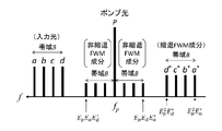
- FIG. 5 is a schematic diagram on the frequency axis showing a state of wavelength conversion by a single pump light using a WDM signal in band B as input light.
- input light corresponding to a 4-channel WDM signal is considered as four line spectra indicated by a, b, c, and d.
- wavelength-converted signal light is obtained as d * , c * , b * , a * (where the asterisk “*” indicates that the phase conjugate light of the original signal light has been generated.
- the non-degenerate FWM generates a non-degenerate FWM component in the band of fp ⁇ B around the pump optical frequency fp.
- the intermediate signal light or output signal light generated by wavelength conversion interferes with the non-degenerate FWM component and is distorted. And the signal quality is significantly degraded.
- the signal light channel closest to the pump light frequency on the frequency axis may be separated from the pump light by a frequency difference larger than the band B of the WDM signal.
- the case where the maximum frequency f3 of the intermediate signal light is set to 191.6 THz in the C band instead of the L band and a WDM signal having a finite band B is input is shown in FIG. ),
- the signal light, the pump light, and the intermediate signal light cannot be made close to each other on the frequency axis, so that the frequency of the signal light cannot be in the vicinity of 191.6 THz, and the input / output wavelength is within the C band. It turns out that it is impossible to set arbitrarily.
- the minimum frequency f2 of the signal light is set to 191.6 + 2B [ Since it is necessary to set a value equal to or higher than [THz], the wavelength band that can be taken by the signal light within the C band is greatly limited.
- FIG. 6 shows various frequency settings used in the experiment.
- the frequency is 196, 195.8, 195.6, 195.45, 195.4, 195.35, 195.2, 195 THz and Case 2 as Case 1. 194.5, 194.3, 194.1, 193.95, 193.9, 193.85, 193.7, 193.5 THz, and Case 3 as 193.1, 192.9, 192.7, 192.55 , 192.5, 192.45, 192.3, and 192.1 THz, which are 8-channel WDM signals arranged at unequal intervals.
- Either Case 1, 2 or 3 is used as the frequency arrangement of the input signal light.
- the first wavelength conversion unit converts the signal light into intermediate signal light
- the second wavelength conversion unit converts the intermediate signal light into Case 1.
- 2 and 3 are converted into output signal light and output.
- the first wavelength conversion unit converts the signal light into intermediate signal light
- the second stage wavelength conversion unit reconverts it to the original frequency arrangement.
- the configuration of the wavelength converter actually constructed is as shown in FIG.
- the input signal optical amplifying unit is designed to flatten the gain in the C band, the optical amplifier EDFA1 having a maximum output of 17 dBm, the high frequency component of the C band with a cutoff frequency of 190.95 THz (1570.005 nm) ( It consists of HPF that allows only short wavelength components) to pass through.
- FIG. 7A shows HPF transfer function measurement results.
- the noise component in the L band where the intermediate signal light is located can be removed, and good signal quality can be expected when the intermediate signal light is generated after the first wavelength conversion.
- the first-stage wavelength conversion unit includes a polarization diversity module whose configuration is shown in FIG. 2, a PM-HNLF having a length of 100 m and a nonlinear constant of about 10 W ⁇ 1 km ⁇ 1 connected thereto, and a cutoff frequency of 190 It consists of a low-pass filter (LPF1) that passes only a low frequency component (long wavelength component) at .3 THz (1575.368 nm).
- LPF1 low-pass filter
- FIG. 7 (b) shows the LPF1 transfer function measurement result.
- Pump light generated and amplified by the first-stage pump light generator is input to the polarization diversity module in the first-stage wavelength converter.
- TLS narrow line width variable wavelength light source 5
- the light is phase-modulated by the optical phase modulator 7 (P Mod.).
- the optical phase modulator includes a phase shifter 8 (PS), an RF signal generated by the oscillator 1 (OSC) of the RF signal generator for pump optical frequency dithering, which is bifurcated. It is applied through an amplifier and an RF low pass filter (LPF) having a cutoff frequency of 400 MHz.
- PS phase shifter 8
- OSC oscillator 1
- LPF RF low pass filter
- the frequency of the RF output from the oscillator 1 does not need to be 300 MHz, and an arbitrary value of about 300 to 400 MHz may be used.
- the continuous light output from the optical phase modulator is amplified to an optical power of 2 W by an optical amplifier, and spontaneous emission light 14 (ASE) noise generated at that time is removed by the BPF, and then the polarizer 6 (Pol.) Is supplied. Then, it is input to the polarization diversity module as pump light.
- ASE spontaneous emission light 14
- the intermediate signal light amplifying unit includes an optical amplifier EDFA2 having a gain flattening design in the L band and a maximum output of 17 dBm, and a low-pass filter LPF2 having a transfer function equivalent to LPF1.
- the LPF 2 can remove noise components existing in the C band, and when the output signal light is generated after the second-stage wavelength conversion, good signal quality can be expected.
- the second-stage wavelength conversion unit can operate from the same polarization diversity module and PM-HNLF as the first stage, and the band pass filter 4 (BPF) that can change the center wavelength and has a pass bandwidth of 1.7 THz. Composed.
- the pass bandwidth is not limited to this value.
- the cutoff frequency is used. May be a value slightly smaller than the minimum frequency f2 of the output signal light, and a high-pass filter 2 (HPF) capable of changing the cutoff frequency according to the output signal light frequency condition may be used.
- HPF high-pass filter 2
- the polarization diversity module in the second-stage wavelength converter receives the pump light generated and amplified by the second-stage pump light generator having the same configuration as the first-stage pump light generator.
- the optical phase modulator of the pump light generator includes the variable attenuator 9 (the other of the two branches of the 300 MHz frequency RF signal generated by the OSC of the pump light frequency dithering RF signal generator 25. ATT), an RF amplifier, and an RF LPF having a cutoff frequency of 400 MHz.
- the phase modulation of the pump light is the signal light after wavelength conversion.
- the effect added as phase noise to the first and second stages can be canceled.
- FIG. 8 shows an experimental system 26 for performing an experiment for evaluating the quality of output signal light whose wavelength is converted by inputting an 8-channel WDM signal as input signal light to the wavelength converter.
- the continuous light output from the eight variable wavelength light sources 5 (TLS) whose oscillation frequency is set to any one of the cases 1, 2, and 3 is combined by the 8 ⁇ 1 polarization maintaining (PM) coupler 18 and polarization multiplexed.
- PM polarization maintaining
- DP Lithium niobate (LN) IQ modulator (IQM) 27 inputs.
- the 4-channel RF signal generated by the arbitrary waveform generator 13 is applied to the DP-LN-IQM 27, and an 8-channel WDM signal is generated in the DP-QPSK format with a symbol rate of 32 Gbaud by modulation.
- the FIG. 9 shows the result of measuring the optical spectrum of the 8-channel WDM signal as the input signal light and overlaying it for the cases 1, 2, and 3.
- the polarization of the signal light is randomly rotated at about 400 kHz by the polarization scrambler 15 (Pol. Scr.), And the wavelength converter 16 shifts the polarization of the input signal light. Make sure it works independently of the wavefront.
- the optical power of the output light whose wavelength has been converted by the wavelength converter is amplified by an optical amplifier, ASE noise outside the signal light band is removed by a band pass filter, and then received by the digital coherent receiver 28 (Rx).
- the OSNR value In order to confirm the quality of the received signal when the OSNR value is changed, optical noise of variable power is added to the signal light before the receiver. At that time, the ASE light source 14 is band-limited by the BPF. It is possible to change the OSNR value of the received signal by amplifying with an optical amplifier and adjusting the optical power with a variable optical attenuator 17 (VOA).
- VOA variable optical attenuator 17
- FIG. 10 shows the measurement result of the optical spectrum output from the polarization diversity module of the first-stage wavelength conversion unit in the wavelength converter.
- the non-degenerate FWM component appears to be quite close to the input signal light or the intermediate signal light.
- FIG. 11 shows the optical spectrum output from the polarization diversity module of the second-stage wavelength converter when the frequency arrangement of the input signal light is Case 1 and the frequency arrangement of the output signal light is Case 1, 2, and 3. The measurement results are shown.
- FIG. 13 shows the light output from the polarization diversity module of the second-stage wavelength converter when the frequency arrangement of the input signal light is Case 3 and the frequency arrangement of the output signal light is Case 1, 2, and 3. The measurement result of a spectrum is shown.
- the 8-channel WDM signal is wavelength-converted as intended.
- the power of the short wavelength side channel of the output signal light is attenuated because of the dispersion characteristics of PM-HNLF, as in the first stage conversion.
- PM-HNLF with a small dispersion slope, the frequency is reduced. It is possible to obtain a flatter waveform on the axis.
- the Q value exceeds 16.5 dB, and it can be said that the output signal light is of high quality. Further, when the bit pattern was verified with respect to the number of bits of about several million under each condition, no bit error was observed.
- FIG. 15 shows the results of measuring the Q value and bit error rate (BER) when the received OSNR is changed for a channel whose frequency is 193.5 THz when the frequency arrangement of the input / output signal light is both Case 2. Indicates.
- the Q value is deteriorated when the OSNR is a large value of 25 dB or more. This is performed before and after the wavelength conversion.
- the ASE noise is slightly added and the waveform is distorted, or the phase modulation component applied to the pump light for SBS suppression is transferred to the phase of the signal light through the FWM, and the waveform is distorted as a slight phase error. It is the result.
- FIG. 15B shows the BER measurement result when the received OSNR is 20 dB or less, but the penalty before and after wavelength conversion is very small for the same reason as above.
- the wavelength converter of the configuration proposed in the present invention is correct for the input WDM signal without depending on the polarization plane of the input signal light under any input / output wavelength conditions within the operating band. It was confirmed that a high-quality output signal light was obtained.
- a wavelength band called C-band having a wavelength range of 1530 to 1565 nm or a frequency range of 195.9 to 191.6 THz is obtained by using the proposed method.
- OSC Oscillator 2
- HPF High pass filter
- band pass filter 301 Low pass filter 302
- LPF 2 Low pass filter 303
- LPF RF signal low pass filter 304
- BPF Band pass filter
- band pass filter 5 TLS: (Narrow line width) wavelength tunable light source 6
- Pol . Polarizer 7
- Phase Mod . Optical phase modulator 8
- PS Phase shifter 9 ATT: Variable attenuator
- 101 EDFA1 Erbium-doped optical fiber amplifier (first optical amplifier)
- EDFA2 Erbium-doped optical fiber amplifier (second optical amplifier)
- PM-HNLF Polarization-maintaining highly nonlinear fiber 12 Pol.
- Polarization diversity module Polarization diversity module 13
- AWG Arbitrary waveform generator 14
- ASE ASE light source, spontaneous emission optical noise source 15
- Wavelength Converter Wavelength converter 17
- VOA Variable optical attenuator 18
- Input signal optical amplifier 20
- First stage wavelength converter 21
- Intermediate signal optical amplifier 22
- Second stage wavelength converter 23
- First stage Eye pump light generation unit Second stage pump light generation unit
- Second stage pump light generation unit Second stage pump light generation unit 25
- DP-LN-IQM polarization multiplexed lithium niobate IQ modulator 28
- Rx digital coherent receiver
Landscapes
- Physics & Mathematics (AREA)
- Nonlinear Science (AREA)
- General Physics & Mathematics (AREA)
- Optics & Photonics (AREA)
- Optical Modulation, Optical Deflection, Nonlinear Optics, Optical Demodulation, Optical Logic Elements (AREA)
- Optical Communication System (AREA)
Abstract
これまで報告された全光波長変換器の手法では、入力信号光が単一波長チャネルの場合に限られる等、波長多重信号に対して、ひずみなく任意の出力波長に変換する動作を実施できなかった。 縮退FWMを二段カスケードする構成の全光波長変換器において、特に一段目変換後に得られる中間信号光に割り当てる波長を明確に規定することで、Cバンド内で任意の帯域を持つ波長多重信号に対して、ひずみなく任意の入出力波長に対する変換動作を実施する。
Description
本発明は光ファイバ通信に利用し得る全光波長変換方法および全光波長変換器に関する。
光ネットワークにおける波長資源利用効率の向上を目的として、ノードで光信号の波長を変換する波長変換器の導入検討が進められている。
光トランシーバーを用いた光-電気/電気-光(OE/EO)変換型の波長変換方式は従来技術にもとづいて実現可能であるが、入力可能な信号のビットレートや変調方式が固定されていて柔軟性がなく、さらに多波長信号を一括して処理することができない。
光トランシーバーを用いた光-電気/電気-光(OE/EO)変換型の波長変換方式は従来技術にもとづいて実現可能であるが、入力可能な信号のビットレートや変調方式が固定されていて柔軟性がなく、さらに多波長信号を一括して処理することができない。
そこで、光信号の波長を光のままで変換する全光波長変換器の研究・開発がなされてきた。
中でも、低損失かつ広帯域な動作が可能であることから、光ファイバ内で発生する非線形効果である四光波混合(FWM)を用いた全光波長変換器が有望視され、様々な手法が提案されてきた。
中でも、低損失かつ広帯域な動作が可能であることから、光ファイバ内で発生する非線形効果である四光波混合(FWM)を用いた全光波長変換器が有望視され、様々な手法が提案されてきた。
縮退FWMを二段カスケードし、一段目の波長変換によって入力信号光をいったん別の波長に変換し(ここで得られる信号光を中間信号光と呼ぶ)、二段目の変換によって中間信号光を動作帯域内の任意の出力波長に変換する構成の全光波長変換器が知られている(非特許文献1~非特許文献3)。
この全光波長変換器は、波長変換動作が不可能となる波長帯を意味する「ガードバンド」を伴わない、任意入出力波長に対応した変換動作を可能とする構成であり、さらには入力信号光の位相が保持され、偏波無依存動作も可能であることから、最も有望である。
S. Petit et al., "Low penalty uniformly tunable wavelength conversion without spectral inversion over 30 nm using SBS-suppressed low-dispersion-slope highly nonlinear fibers," IEEE Photon. Technol. Lett., vol. 23, no. 9, pp. 546-548, May 2011.
T. Inoue et al., "Guard-band-less and polarization-insensitive tunable wavelength converter for phase-modulated signals: demonstration and signal quality analyses," J. Lightw. Technol., vol. 32, no. 10, pp. 1981-1990, May 2014.
H. Nguyen Tan et al., "On the Cascadability of All-Optical Wavelength Converter for High-Order QAM Formats," J. Lightw. Technol., vol. 34, no. 13, pp. 3194-3205, July 2016.
実用性を考えると、波長範囲が1530~1565nmあるいは周波数範囲が195.9~191.6THzであるCバンドと呼ばれる波長帯を動作帯域として、この中で任意の帯域および中心波長を持つ波長多重信号に対して、ひずみなく任意の出力波長に変換する動作を実施できることが重要である。
しかしながら、これまで報告された全光波長変換器の手法では、入力信号光が単一波長チャネルの場合に限られる等、要求される動作を確実に実施する方法が明らかにされていなかった。
本発明では、縮退FWMを二段カスケードする構成の全光波長変換器において、特に一段目変換後に得られる中間信号光に割り当てる波長を明確に規定することで、Cバンド内で任意の帯域を持つ波長多重信号に対して、ひずみなく任意の入出力波長に対する変換動作を実施する方法および波長変換器を提案する。
(1)所定の周波数範囲を動作帯域とし、前記動作帯域内で任意の波長(搬送光周波数)を持つ入力信号光に対して、前記入力信号光が持つ情報を保持しつつ、光領域で前記入力信号光の波長を前記動作帯域内において任意の出力信号光の波長に変換する波長変換方法であって、
前記入力信号光を前記動作帯域内で利得平坦化設計を施された第1光増幅器により増幅し、
次に当該増幅された前記入力信号光とその波長に応じて当該波長が設定される一段目ポンプ光により第一の非線形媒体で発生する縮退四光波混合による一段目の波長変換によって前記入力信号光の波長を動作帯域外の中間信号光の波長に変換し、
次に前記中間信号光を第2光増幅器により増幅し、
次に当該増幅された前記中間信号光とその波長に応じて当該波長が設定される二段目ポンプ光により第二の非線形媒体で発生する縮退四光波混合による二段目の波長変換によって前記中間信号光の波長を前記動作帯域内の前記任意の出力信号光の波長に変換する場合において、
前記入力信号光の最大周波数をf1、最小周波数をf2、信号帯域をB=f1-f2とし、さらに前記中間信号光の最大周波数をf3、最小周波数をf4=f3-Bとし、前記動作帯域の最小周波数を191.2THzより大きい値とし、かつ、前記中間信号光の最大周波数f3を191.2THz以下のある値に固定し、
そして第2光増幅器に前記f3以下の周波数帯で利得平坦化設計を施すことにより、
前記出力信号光の波長をひずみなく出力するように制御したこと、
を特徴とする波長変換方法。
前記入力信号光を前記動作帯域内で利得平坦化設計を施された第1光増幅器により増幅し、
次に当該増幅された前記入力信号光とその波長に応じて当該波長が設定される一段目ポンプ光により第一の非線形媒体で発生する縮退四光波混合による一段目の波長変換によって前記入力信号光の波長を動作帯域外の中間信号光の波長に変換し、
次に前記中間信号光を第2光増幅器により増幅し、
次に当該増幅された前記中間信号光とその波長に応じて当該波長が設定される二段目ポンプ光により第二の非線形媒体で発生する縮退四光波混合による二段目の波長変換によって前記中間信号光の波長を前記動作帯域内の前記任意の出力信号光の波長に変換する場合において、
前記入力信号光の最大周波数をf1、最小周波数をf2、信号帯域をB=f1-f2とし、さらに前記中間信号光の最大周波数をf3、最小周波数をf4=f3-Bとし、前記動作帯域の最小周波数を191.2THzより大きい値とし、かつ、前記中間信号光の最大周波数f3を191.2THz以下のある値に固定し、
そして第2光増幅器に前記f3以下の周波数帯で利得平坦化設計を施すことにより、
前記出力信号光の波長をひずみなく出力するように制御したこと、
を特徴とする波長変換方法。
(2)(1)に記載の波長変換方法であって、
前記入力信号光が波長多重信号であること、
を特徴とする波長変換方法。
前記入力信号光が波長多重信号であること、
を特徴とする波長変換方法。
(3)(1)または(2)のいずれかに記載の波長変換方法であって、
前記一段目の波長変換が行われた直後に、前記一段目の波長変換で用いられた前記一段目ポンプ光の周波数の最小値よりも小さなカットオフ周波数をもつ低域通過フィルタを用いて、前記入力信号光と前記一段目ポンプ光を除去して前記中間信号光のみ通過させること、
を特徴とする波長変換方法。
前記一段目の波長変換が行われた直後に、前記一段目の波長変換で用いられた前記一段目ポンプ光の周波数の最小値よりも小さなカットオフ周波数をもつ低域通過フィルタを用いて、前記入力信号光と前記一段目ポンプ光を除去して前記中間信号光のみ通過させること、
を特徴とする波長変換方法。
(4)(1)または(3)のいずれかに記載の波長変換方法であって、
前記動作帯域の最小周波数をfminとしたとき、
fmin-f3>2Bを満たすこと、
を特徴とする波長変換方法。
(5)(1)または(4)のいずれかに記載の方法であって、
前記非線形媒体が光ファイバであること、
を特徴とする波長変換方法。
前記動作帯域の最小周波数をfminとしたとき、
fmin-f3>2Bを満たすこと、
を特徴とする波長変換方法。
(5)(1)または(4)のいずれかに記載の方法であって、
前記非線形媒体が光ファイバであること、
を特徴とする波長変換方法。
(6)第1光増幅器を備えた入力信号光増幅部を入力部とし、順に接続された一段目波長変換部と第2光増幅器を備えた中間信号光増幅部および二段目長変換部からなり、
前記一段目波長変換部および二段目波長変換部にはポンプ光周波数ディザリング用RF信号発生部に接続された一段目ポンプ光発生部および二段目ポンプ光発生部がそれぞれ接続され、
所定の周波数範囲を動作帯域とし、前記動作帯域内で任意の波長(搬送光周波数)を持つ入力信号光に対して、前記入力信号光が持つ情報を保持しつつ、光領域で前記入力信号光の波長を前記動作帯域内において任意の出力信号光の波長に変換する波長変換器であって、
入力信号光増幅部において前記入力信号光を前記動作帯域内で利得平坦化設計を施された第1光増幅器により増幅し、
次に一段目波長変換部において当該増幅された前記入力信号光とその波長に応じて当該波長が設定される一段目ポンプ光により第一の非線形媒体で発生する縮退四光波混合による一段目の波長変換によって前記入力信号光の波長を動作帯域外の中間信号光の波長に変換し、
次に前記中間信号光増幅部において前記中間信号光を第2光増幅器により増幅し、
次に前記二段目長変換部において当該増幅された前記中間信号光とその波長に応じて当該波長が設定される二段目ポンプ光により第二の非線形媒体で発生する縮退四光波混合による二段目の波長変換によって前記中間信号光の波長を前記動作帯域内の前記任意の出力信号光の波長に変換する場合において、
前記入力信号光の最大周波数をf1、最小周波数をf2、信号帯域をB=f1-f2とし、さらに前記中間信号光の最大周波数をf3、最小周波数をf4=f3-Bとし、前記動作帯域の最小周波数を191.2THzより大きい値とし、かつ、前記中間信号光の最大周波数f3を191.2THz以下のある値に固定し、
そして第2光増幅器に前記f3以下の周波数帯で利得平坦化設計を施すことにより、
前記出力信号光の波長をひずみなく出力するように制御したこと、
を特徴とする波長変換器。
前記一段目波長変換部および二段目波長変換部にはポンプ光周波数ディザリング用RF信号発生部に接続された一段目ポンプ光発生部および二段目ポンプ光発生部がそれぞれ接続され、
所定の周波数範囲を動作帯域とし、前記動作帯域内で任意の波長(搬送光周波数)を持つ入力信号光に対して、前記入力信号光が持つ情報を保持しつつ、光領域で前記入力信号光の波長を前記動作帯域内において任意の出力信号光の波長に変換する波長変換器であって、
入力信号光増幅部において前記入力信号光を前記動作帯域内で利得平坦化設計を施された第1光増幅器により増幅し、
次に一段目波長変換部において当該増幅された前記入力信号光とその波長に応じて当該波長が設定される一段目ポンプ光により第一の非線形媒体で発生する縮退四光波混合による一段目の波長変換によって前記入力信号光の波長を動作帯域外の中間信号光の波長に変換し、
次に前記中間信号光増幅部において前記中間信号光を第2光増幅器により増幅し、
次に前記二段目長変換部において当該増幅された前記中間信号光とその波長に応じて当該波長が設定される二段目ポンプ光により第二の非線形媒体で発生する縮退四光波混合による二段目の波長変換によって前記中間信号光の波長を前記動作帯域内の前記任意の出力信号光の波長に変換する場合において、
前記入力信号光の最大周波数をf1、最小周波数をf2、信号帯域をB=f1-f2とし、さらに前記中間信号光の最大周波数をf3、最小周波数をf4=f3-Bとし、前記動作帯域の最小周波数を191.2THzより大きい値とし、かつ、前記中間信号光の最大周波数f3を191.2THz以下のある値に固定し、
そして第2光増幅器に前記f3以下の周波数帯で利得平坦化設計を施すことにより、
前記出力信号光の波長をひずみなく出力するように制御したこと、
を特徴とする波長変換器。
(7)(1)に記載の波長変換器であって、
前記入力信号光が波長多重信号であること
を特徴とする波長変換器。
(8)(6)または(7)のいずれかに記載の波長変換器であって、
前記中間信号光増幅部において前記一段目ポンプ光の周波数の最小値よりも小さなカットオフ周波数をもつ低域通過フィルタを用いて、前記入力信号光と前記一段目ポンプ光を除去して前記中間信号光のみ通過させること、
を特徴とする波長変換器。
(9)(6)または(8)のいずれかに記載の波長変換器であって、
前記動作帯域の最小周波数をfminとしたとき、
fmin-f3>2Bを満たすこと、
を特徴とする波長変換器。
(10)(6)または(9)のいずれかに記載の波長変換器であって、
前記非線形媒体が光ファイバであること、
を特徴とする波長変換器。
前記入力信号光が波長多重信号であること
を特徴とする波長変換器。
(8)(6)または(7)のいずれかに記載の波長変換器であって、
前記中間信号光増幅部において前記一段目ポンプ光の周波数の最小値よりも小さなカットオフ周波数をもつ低域通過フィルタを用いて、前記入力信号光と前記一段目ポンプ光を除去して前記中間信号光のみ通過させること、
を特徴とする波長変換器。
(9)(6)または(8)のいずれかに記載の波長変換器であって、
前記動作帯域の最小周波数をfminとしたとき、
fmin-f3>2Bを満たすこと、
を特徴とする波長変換器。
(10)(6)または(9)のいずれかに記載の波長変換器であって、
前記非線形媒体が光ファイバであること、
を特徴とする波長変換器。
C-band内で任意の帯域を持つ波長多重信号に対して、任意の入出力波長に対応する全光波長変換動作をひずみなく実施することが可能となる。
まず本発明を実施するための波長変換器の基本構成を説明する(非特許文献3)。
図1は波長変換器の内部構成を表す図である。
図1は波長変換器の内部構成を表す図である。
入力される信号光は、ある動作帯域内に中心波長(搬送光周波数)を持っていて、これが波長変換器に入力されると、入力信号光増幅部19、一段目波長変換部20、中間信号光増幅部21、二段目波長変換部22を経て、その中心波長(搬送光周波数)が動作帯域内の任意の値に変換されて出力される。
入力信号光増幅部および中間信号光増幅部は、光増幅器と光学フィルタからなる。
図1には記載されていないが、二段目波長変換部の後に出力信号光増幅部として、やはり光増幅器と光学フィルタを備えていてもよい。
一方で、入力信号光が必要十分な光パワーを持っている場合、波長変換器は入力信号光増幅部を備えていなくともよく、入力信号光が一段目波長変換部に直接入力される構成であってもよい。
図1には記載されていないが、二段目波長変換部の後に出力信号光増幅部として、やはり光増幅器と光学フィルタを備えていてもよい。
一方で、入力信号光が必要十分な光パワーを持っている場合、波長変換器は入力信号光増幅部を備えていなくともよく、入力信号光が一段目波長変換部に直接入力される構成であってもよい。
一段目および二段目の波長変換部は、偏波ダイバーシティモジュール12とそれに接続された偏波保持高非線形ファイバ11(PM-HNLF)、そして光学フィルタ4からなり、各段の偏波ダイバーシティモジュールには、それぞれ一段目および二段目ポンプ光発生部によって発生された、波長可変かつハイパワーの連続光がポンプ光として入力される。
各段のPM-HNLF内では単一ポンプ光による縮退FWMが発生し、一段目の波長変換によって入力信号光が動作帯域外のある波長を持つ中間信号光として変換され、次に二段目の波長変換によって中間信号光が動作帯域内のある波長を持つ出力信号光に変換される。
一段目および二段目波長変換部に供給されるポンプ光の波長を適切な値に変更することで、動作帯域内で任意の入出力波長の組み合わせに対応した可変波長変換動作が可能となる。
なお図1では、FWMを発生させるための非線形媒体として偏波保持特性および高非線形性を持ち、材料として石英ガラスをベースとする光ファイバの利用を考えているが、非線形媒体としてはシリコンや窒化シリコンを材料とする導波路型デバイス、あるいはカルコゲナイドガラスを用いた光ファイバや導波路型デバイス、もしくは半導体光増幅器(SOA)なども利用可能である。この中で、現状では前記のPM-HNLFが偏波保持特性、累積非線形効果、挿入損失、他の光ファイバとの接続性等の観点から、最良の非線形媒体である。
なお図1では、FWMを発生させるための非線形媒体として偏波保持特性および高非線形性を持ち、材料として石英ガラスをベースとする光ファイバの利用を考えているが、非線形媒体としてはシリコンや窒化シリコンを材料とする導波路型デバイス、あるいはカルコゲナイドガラスを用いた光ファイバや導波路型デバイス、もしくは半導体光増幅器(SOA)なども利用可能である。この中で、現状では前記のPM-HNLFが偏波保持特性、累積非線形効果、挿入損失、他の光ファイバとの接続性等の観点から、最良の非線形媒体である。
図2に構成を示す偏波ダイバーシティモジュール12を用いることで、FWMの動作が入力信号光の偏波面(偏光面)に依存しない、偏波無依存波長変換動作が可能である。
さらに、各段の波長変換プロセスにおいては、ハイパワーポンプ光によって光ファイバ中に引き起こされる誘導ブリルアン散乱(SBS)を抑圧するため、ポンプ光の波長(周波数)が位相変調されており(これをディザリングと呼ぶ)、そのために各段のポンプ光発生部23,24では光位相変調器7が用いられ、これにポンプ光周波数ディザリング用RF信号発生部25において発生させた周波数が300MHz程度のRF信号が印加される。
このとき、RF信号を二分岐してそれぞれの強度差と相対位相を調整し、一段目と二段目のポンプ光に対する位相変調を同期させることで、FWMを通じて出力信号光に付加される位相変調の効果をキャンセルする「カウンターディザー」が可能となる。
本発明の目的は、さらに、C-band内で任意の中心波長を持つWDM信号に対して、周波数(波長)軸での波形ひずみを発生させることなく、任意の入出力波長条件に対応する変換動作を実施することであり、そのために必要な各種の周波数の設定について以下に述べる。
図3は、波長変換時の信号光、ポンプ光、そして中間信号光のスペクトルを周波数軸上で示したものである。
動作帯域をfmax>=f>=fminとし、例えばfmax=195.9THz(1530.334nm)、fmin=191.2THz(1567.952nm)とおくと、動作帯域がCバンド帯をカバーすることになる。
この動作帯域の中に、帯域がBのWDM信号が存在し、WDM信号の最大および最小周波数をそれぞれf1およびf2とすると、B=f1-f2である。
一方、中間信号光の最大および最小周波数をそれぞれf3およびf4とすると、B=f3-f4である。このとき、ポンプ光の周波数はfp=(f2+f3)/2でなければならない。
なお、この図に示した波長変換の状況は、一段目および二段目の波長変換部双方で見られるものであり、一段目の波長変換を考える場合、周波数がf1>=f>=f2の信号光は入力信号光を意味し、これがf3>=f>=f4の中間信号光に変換される。
また、二段目を考える場合、信号光は出力信号光を意味し、中間信号光から出力信号光へと変換されることになる。
また、ここで考える波長変換は縮退FWMによるものであるので、波長変換前後で周波数f1の信号光とf4の中間信号光が対応し、さらにf2の信号光とf3の中間信号光が対応していて、波長変換前後で対応する信号光どうしは位相共役の関係にある。
また、ここで考える波長変換は縮退FWMによるものであるので、波長変換前後で周波数f1の信号光とf4の中間信号光が対応し、さらにf2の信号光とf3の中間信号光が対応していて、波長変換前後で対応する信号光どうしは位相共役の関係にある。
ところで、従来知られている波長変換方式においては、中間信号光の周波数f3およびf4に対する制限は存在せず、中間信号光がCバンド内に存在することもあった。
この場合、入力信号光が単一チャネルであるなら、中間信号光の周波数を柔軟に設定することで、動作に支障はきたさない。
この場合、入力信号光が単一チャネルであるなら、中間信号光の周波数を柔軟に設定することで、動作に支障はきたさない。
ところが、有限の帯域Bを持つWDM信号の入力に対しては、入力信号光の中心周波数や帯域幅の条件によって、中間信号光の周波数帯がCバンドのみならず、周波数がf<191.6THzであるLバンド帯に及ぶ場合が生じる。
CおよびLバンドにまたがるWDM信号を平坦な利得で増幅する装置は容易に入手可能ではないため、波長変換後の増幅動作に問題が生じる。
そこで本発明では、中間信号光の最大周波数f3をLバンド内の例えばf3=191.2THz (1567.952nm)に固定し、f4=f3-Bと設定することにより、問題を解決する。
そこで本発明では、中間信号光の最大周波数f3をLバンド内の例えばf3=191.2THz (1567.952nm)に固定し、f4=f3-Bと設定することにより、問題を解決する。
図4(a)~図4(c)は、fmax=195.9THz,fmin=191.6THz,f3=191.2THzとおいたときの、帯域がB[THz]である信号光に対する波長変換動作時のスペクトルを周波数軸上で示したものである。
図4(a)は信号光の周波数設定に関して一般的な条件に対応する図であり、図4(b)および(c)は、信号光の周波数がそれぞれ最も低周波側および高周波側に設定された場合に対応する。
いずれの場合も、中間信号光の最大周波数f3は191.2THzに固定されている。
このとき、ポンプ光の周波数fpは、信号光の最小周波数f2によって決定され、fp=(f2+f3)/2=(f2+191.2)/2[THz]と与えられる。
いずれの場合も、中間信号光の最大周波数f3は191.2THzに固定されている。
このとき、ポンプ光の周波数fpは、信号光の最小周波数f2によって決定され、fp=(f2+f3)/2=(f2+191.2)/2[THz]と与えられる。
図4(b)のとき、すなわち信号光の最小周波数f2が動作帯域の最小周波数fmin=191.6THzに一致するとき、ポンプ光周波数が最小値fp=(191.6+191.2)/2=191.4THzとなる。
一方、図4(c)の場合でB=0すなわち周波数が195.9THzで単一チャネルの信号光に対しては、ポンプ光周波数が最大値fp=(195.9+191.2)/2=193.55 THzをとる。
ここで重要な点は、入出力信号光は常にCバンド帯に、そして中間信号光は常にf<191.2THzであるLバンド帯に存在することから、図1のEDFA1およびEDFA2として、それぞれCおよびLバンド用に利得平坦化設計を施された光増幅器を用いることにより、波長変換動作時に各チャネルに対して平坦な利得でWDM信号を増幅することができ、任意の帯域を持つWDM信号に対して、周波数軸でひずみのない、任意の入出力波長に対する波長変換動作が初めて可能となるのである。
これに対して、波長多重信号に対して周波数軸で平坦でない波長変換動作がなされ、周波数軸上で波長多重信号全体の波形にひずみが生じる場合、波長多重信号の一部のチャネルの信号パワーが小さくなり、そのチャネルの信号対雑音比が劣化することで、時間軸での波形も雑音に埋もれて大きなひずみを持つことになる。
なお中間信号光の最大周波数f3の値は191.2THzである必要はなく、191.2THz以下の値でLバンド帯に存在していればよい。
これに対して、波長多重信号に対して周波数軸で平坦でない波長変換動作がなされ、周波数軸上で波長多重信号全体の波形にひずみが生じる場合、波長多重信号の一部のチャネルの信号パワーが小さくなり、そのチャネルの信号対雑音比が劣化することで、時間軸での波形も雑音に埋もれて大きなひずみを持つことになる。
なお中間信号光の最大周波数f3の値は191.2THzである必要はなく、191.2THz以下の値でLバンド帯に存在していればよい。
また前記光増幅器として必ずしも利得平坦化設計がなされていなくても、CおよびLバンド用に設計され、利得が一定の平坦度を持つ光増幅器を用いることで、周波数軸上でのひずみが許容される範囲内で、WDM信号に対しての波長変換動作を行うことは可能である。
さらに本発明の方法は、WDM信号ではなく例えば単一チャネルながら帯域が数nm以上の超高帯域信号に対しても有効に動作する。
一段目波長変換部の偏波ダイバーシティモジュール出力時に、中間信号光のみを抽出し、入力信号光とポンプ光を除去する必要があるが、図4(a)~図4(c)の場合には中間信号光の最大周波数が191.2THzで、ポンプ光の最小周波数が191.4THzであるから、カットオフ周波数が191.3THz程度で伝達関数が固定のローパスフィルタ(LPF;図1ではLPF1として記載している、低域通過フィルタ)を用いれば、入力信号光の周波数配置およびポンプ光周波数に関する任意の条件に対して、入力信号光とポンプ光を除去するという目的を達成することができる。
そのようなLPFは、誘電体多層膜を用いて比較的安価に製造することができて容易に入手が可能であり、しかも高パワーの入力光に対して耐性があるので、いま考えている用途において大変有用である。
なお二段目波長変換部の偏波ダイバーシティモジュール出力時には、ポンプ光がCバンド帯に存在することがある(例えば図4(c)の場合)ため、例えばカットオフ周波数が191.3THz程度で伝達関数が固定されているハイパスフィルタ2(HPF、高域通過フィルタ)で中間信号光とポンプ光を除去したうえで出力信号光のみを抽出することはできず、中心波長の可変動作ができるHPFもしくは帯域通過フィルタ4(BPF)を用いる必要がある。
ところで、光ファイバ中のFWMを用いてWDM信号の波長変換を行う際、動作原理として利用したい縮退FWMだけではなく、同時に非縮退FWMも発生し、その結果出力光として望ましからぬ周波数成分まで発生することになる。
図5は帯域BのWDM信号を入力光として、単一ポンプ光による波長変換の様子を周波数軸上で示した模式図である。
ただし図5では簡単な一例として、4チャネルWDM信号に相当する入力光をa,b,c,dで示した四本の線スペクトルとして考えている。
ただし図5では簡単な一例として、4チャネルWDM信号に相当する入力光をa,b,c,dで示した四本の線スペクトルとして考えている。
縮退FWMの結果として、波長変換された信号光がd*,c*,b*,a*として得られるが(ここでアスタリスク「*」は、元の信号光の位相共役光が発生したことを表す)、同時に非縮退FWMによって、ポンプ光周波数fpを中心としてfp±Bの帯域内に非縮退FWM成分が発生する。
例えば、入力信号光a,dおよびポンプ光pの電場複素振幅をそれぞれEa,Ed,Epとおくとき、(EpEaEd *)や(EpEdEa *)で表される成分などが非縮退FWMによるものである。
例えば、入力信号光a,dおよびポンプ光pの電場複素振幅をそれぞれEa,Ed,Epとおくとき、(EpEaEd *)や(EpEdEa *)で表される成分などが非縮退FWMによるものである。
信号光が存在している周波数帯域と、非縮退FWM成分が発生する帯域fp±Bが重なっていると、波長変換によって発生した中間信号光もしくは出力信号光が非縮退FWM成分と干渉してひずみを発生し、信号品質が著しく低下することになる。
これを避けるためには、周波数軸上でポンプ光周波数に最も近い信号光チャネルが、ポンプ光に対して、WDM信号の帯域Bより大きい周波数差で離れていればよい。
図3の場合で言えば、f2-fp=fp-f3>Bが常に満たされるよう、各種周波数の値を設定すればよい。
すなわち、中間信号光の最大周波数f3と動作帯域の最小周波数fminが、fmin-f3>2Bの関係を満たしていればよい。
図3の場合で言えば、f2-fp=fp-f3>Bが常に満たされるよう、各種周波数の値を設定すればよい。
すなわち、中間信号光の最大周波数f3と動作帯域の最小周波数fminが、fmin-f3>2Bの関係を満たしていればよい。
以上に示した構成を用いることで、Cバンド内で任意の帯域を持つWDM信号に対して、入出力波長を任意に設定した波長変換動作を、周波数軸上でひずみなく実施することができるようになる。
なお本発明の比較例として、中間信号光の最大周波数f3をLバンドではなく、Cバンド内の191.6THzに設定して、有限の帯域Bを持つWDM信号を入力した場合を図4(d)に示すと、信号光とポンプ光および中間信号光を周波数軸上ですき間なく近づけることはできないため、信号光の周波数として191.6THz付近を用いることができず、入出力波長をCバンド内で任意に設定することが不可能なことがわかる。
特に、上述した条件、f2-fp=fp-f3>Bを満たすように各種周波数を設定する場合には、図4(d)に明らかなように、信号光の最小周波数f2を191.6+2B[THz]以上の値に設定する必要が生じるため、Cバンド内で信号光の取り得る波長帯に大きな制限を生じることになる。
特に、上述した条件、f2-fp=fp-f3>Bを満たすように各種周波数を設定する場合には、図4(d)に明らかなように、信号光の最小周波数f2を191.6+2B[THz]以上の値に設定する必要が生じるため、Cバンド内で信号光の取り得る波長帯に大きな制限を生じることになる。
以下では、具体的な実験結果をもとに、本発明の有効性について述べる。
図6に実験で用いる各種の周波数設定を示す。
動作帯域をfmax=196THz(1529.553nm)およびfmin=192.1THz(1560.606nm)とおき、入力するWDM信号の帯域をB=1THz、中間信号光の最大周波数をf3=189.8THz(1579.518nm)と固定する。
このとき、中間信号光の最小周波数は自動的にf4=188.8THzと決定される。
図6に実験で用いる各種の周波数設定を示す。
動作帯域をfmax=196THz(1529.553nm)およびfmin=192.1THz(1560.606nm)とおき、入力するWDM信号の帯域をB=1THz、中間信号光の最大周波数をf3=189.8THz(1579.518nm)と固定する。
このとき、中間信号光の最小周波数は自動的にf4=188.8THzと決定される。
入出力信号光の周波数配置として三つのパターンを考えることにし、Case1として周波数が196,195.8,195.6,195.45,195.4,195.35,195.2,195THz、Case2として194.5,194.3,194.1,193.95,193.9,193.85,193.7,193.5THz、そしてCase3として193.1,192.9,192.7,192.55,192.5,192.45,192.3,192.1THzという不等間隔に配置された8チャネルのWDM信号を考える。
入力信号光の周波数配置としてCase1,2,3のいずれかを用い、どの場合でも一段目の波長変換部で中間信号光へと変換し、さらに二段目の波長変換部では中間信号光をCase1,2,3いずれかの出力信号光に変換して出力する。
結局、入出力信号光の周波数の配置に関して、合計9通りの波長変換実験を実施する。
なお一段目あるいは二段目の波長変換部双方において、入力あるいは出力信号光の周波数配置がCase1,2,3の場合、ポンプ光周波数はそれぞれfp=192.4,191.65,190.95THzである。
なお一段目あるいは二段目の波長変換部双方において、入力あるいは出力信号光の周波数配置がCase1,2,3の場合、ポンプ光周波数はそれぞれfp=192.4,191.65,190.95THzである。
また、入出力信号光が同じ周波数配置である場合も、一段目の波長変換部で中間信号光に変換し、二段目の波長変換部でもとの周波数配置に再変換するという操作を実施する。
実際に構築した波長変換器の構成は図1の通りである。
入力信号光増幅部は、Cバンド帯で利得平坦化設計を施され、最大出力が17dBmである光増幅器EDFA1と、カットオフ周波数が190.95THz(1570.005nm)でCバンド帯の高周波成分(短波長成分)のみを通過させるHPFからなる。
入力信号光増幅部は、Cバンド帯で利得平坦化設計を施され、最大出力が17dBmである光増幅器EDFA1と、カットオフ周波数が190.95THz(1570.005nm)でCバンド帯の高周波成分(短波長成分)のみを通過させるHPFからなる。
図7(a)にHPFの伝達関数測定結果を示す。
このHPFを用いることで、中間信号光が位置するLバンド帯の雑音成分を除去することができて、一段目の波長変換後に中間信号光が生成される際、良好な信号品質が期待できる。
このHPFを用いることで、中間信号光が位置するLバンド帯の雑音成分を除去することができて、一段目の波長変換後に中間信号光が生成される際、良好な信号品質が期待できる。
一段目波長変換部は、図2に構成を示した偏波ダイバーシティモジュールと、それに接続された長さが100mで非線形定数が約10W-1km-1のPM-HNLF、そしてカットオフ周波数が190.3THz(1575.368nm)で低周波成分(長波長成分)のみを通過させるローパスフィルタ(LPF1)からなる。
図7(b)にLPF1の伝達関数測定結果を示すが、これを用いることにより、Case 1,2,3いずれの周波数条件においても、一段目波長変換部出力における入力信号光および残留ポンプ光を常に除去し、中間信号光のみを出力させることが可能である。
一段目波長変換部内の偏波ダイバーシティモジュールには、一段目ポンプ光発生部で発生および増幅されたポンプ光が入力される。
一段目ポンプ光発生部では、狭線幅波長可変光源5(TLS)で発生されたある周波数(ポンプ光周波数である、fp=192,4,191.65,190.95THzのいずれか)の連続光が、光位相変調器7(P Mod.)によって位相変調される。
一段目ポンプ光発生部では、狭線幅波長可変光源5(TLS)で発生されたある周波数(ポンプ光周波数である、fp=192,4,191.65,190.95THzのいずれか)の連続光が、光位相変調器7(P Mod.)によって位相変調される。
光位相変調器には、ポンプ光周波数ディザリング用RF信号発生部の発振器1(OSC)で発生された周波数300MHzのRF信号が二分岐されたうちの一方が、位相シフタ8(PS)、RF増幅器、そしてカットオフ周波数が400MHzであるRF用ローパスフィルタ(LPF)を経て印加されている。
ポンプ光の位相変調によって、PM-HNLFにおける誘導ブリルアン散乱(SBS)を抑圧する効果がある。なお発振器1より出力されるRFの周波数は300MHzである必要はなく、300~400MHz程度の任意の値を用いてもよい。
光位相変調器より出力された連続光は、光増幅器によって光パワーが2Wまで増幅され、その際発生した自然放出光14(ASE)雑音がBPFによって除去された後、ポラライザ6(Pol.)を経て、ポンプ光として偏波ダイバーシティモジュールに入力される。
中間信号光増幅部は、Lバンド帯で利得平坦化設計を施され、最大出力が17dBmである光増幅器EDFA2と、伝達関数がLPF1と同等のローパスフィルタLPF2からなる。
LPF2によって、Cバンド帯に存在する雑音成分を除去することができて、二段目の波長変換後に出力信号光が生成される際、良好な信号品質が期待できる。
二段目波長変換部は、一段目と同様の偏波ダイバーシティモジュールとPM-HNLF、そして中心波長を変更する動作が可能で、通過帯域幅が1.7THzである帯域通過フィルタ4(BPF)から構成される。
二段目波長変換部は、一段目と同様の偏波ダイバーシティモジュールとPM-HNLF、そして中心波長を変更する動作が可能で、通過帯域幅が1.7THzである帯域通過フィルタ4(BPF)から構成される。
ただし通過帯域幅はこの値に限るものではない。このBPFを用いることにより、二段目波長変換部出力において中間信号光および残留ポンプ光を除去し、所望の出力信号光のみを抽出することが可能であるが、BPFの代わりに、カットオフ周波数が出力信号光の最小周波数f2よりやや小さい値であり、出力信号光周波数条件に応じてカットオフ周波数の変更動作が可能なハイパスフィルタ2(HPF)を用いてもよい。
二段目波長変換部内の偏波ダイバーシティモジュールには、一段目ポンプ光発生部と同様の構成である二段目ポンプ光発生部で発生および増幅されたポンプ光が入力されるが、二段目ポンプ光発生部の光位相変調器には、ポンプ光周波数ディザリング用RF信号発生部25のOSCで発生された周波数300MHzのRF信号が二分岐されたうちのもう一方が、可変減衰器9(ATT)、RF増幅器、そしてカットオフ周波数が400MHzであるRF用LPFを経て印加される。
このとき、一段目および二段目のポンプ光発生部の各光位相変調器に印加されるRF信号の強度と位相を適当に調整することで、ポンプ光の位相変調が波長変換後の信号光に位相雑音として付加される効果を一段目と二段目でキャンセルさせることができる。
図8に8チャネルWDM信号を入力信号光として波長変換器に入力し、波長が変換された出力信号光の品質を評価する実験を行うための実験系26を示す。
発振周波数が前記Case1,2,3のいずれかに設定された8個の波長可変光源5(TLS)より出力される連続光を8x1偏波保持(PM)カプラ18で合波し、偏波多重(DP)リチウムニオブ酸(LN)IQ変調器(IQM)27に入力する。
DP-LN-IQM27には、任意波形発生器13(AWG)で発生された4チャネルのRF信号が印加され、変調によりシンボルレートが32GbaudであるDP-QPSKフォーマットで8チャネルのWDM信号が生成される。
図9にCase1,2,3それぞれの場合について、入力信号光としての8チャネルWDM信号の光スペクトルを測定して、これを重ね描きした結果を示す。
図9にCase1,2,3それぞれの場合について、入力信号光としての8チャネルWDM信号の光スペクトルを測定して、これを重ね描きした結果を示す。
光増幅器で入力信号光の光パワーを増幅した後、偏波スクランブラ15(Pol.Scr.)で信号光の偏波を約400kHzでランダムに回転させ、波長変換器16が入力信号光の偏波面に依存せずに動作することを確認する。
波長変換器で波長が変換された出力光の光パワーを光増幅器で増幅し、帯域通過フィルタで信号光帯域外のASE雑音を除去した後、デジタルコヒーレント受信機28(Rx)で受信する。
波長変換器で波長が変換された出力光の光パワーを光増幅器で増幅し、帯域通過フィルタで信号光帯域外のASE雑音を除去した後、デジタルコヒーレント受信機28(Rx)で受信する。
なお、OSNR値を変化させたときの受信信号の品質を確認するために、受信機の手前で可変パワーの光雑音を信号光に付加するが、その際ASE光源14をBPFにより帯域制限して光増幅器で増幅し、可変光減衰器17(VOA)でその光パワーを調整することで、受信信号のOSNR値を変更することが可能である。
図10に波長変換器内の一段目波長変換部の偏波ダイバーシティモジュールより出力される光スペクトルの測定結果を示す。
入力信号光の周波数配置がCase1,2,3いずれの場合も、同じ周波数(波長)配置189.8>f>188.8[THz](波長で言うと1579.518~1587.884nm)の中間信号光に変換されているのがわかる。
図10(b)および(c)に示したCase2,3の場合に、中間信号光の長波長側チャネルのパワーが減衰していて、周波数軸上でひずんで見えるが、これはPM-HNLFの分散の効果によって縮退FWMによる波長変換効率が劣化したためである。
一方、Case1の場合は平坦な出力スペクトルが得られているように見えるが、これは短波長側における光増幅器の利得平坦度が悪く、図9に示した通り、入力信号光のパワーが短波側チャネルで大きく出てしまったため、波長変換効率のスロープと打ち消しあって、出力光の各チャネルが周波数軸上で平坦に見えたためである。
分散スロープのより小さなPM-HNLFを用いることで、波長変換効率の周波数スロープをキャンセルし、より平坦でひずみのない中間信号光を得ることが可能である。
一方、それぞれの場合でポンプ光の周辺帯域に非縮退FWMによる成分が多数発生しているのがわかる。
一方、それぞれの場合でポンプ光の周辺帯域に非縮退FWMによる成分が多数発生しているのがわかる。
特に図10(c)に示した、入力信号光の周波数配置がCase3の場合において、非縮退FWM成分は入力信号光あるいは中間信号光にかなり近接しているように見える。
しかしながら、ポンプ光周波数fp=190.95THzと入力信号光の最小周波数f2=192.1THz、そしてポンプ光周波数fpと中間信号光の最大周波数f3=189.8THzにはともに1.15THzの差が設定されていて、この差が信号帯域B=1THzを上回っていることから、非縮退FWM成分と信号光が干渉することはなく、信号品質に影響を及ぼさない。
図11に入力信号光の周波数配置がCase1であって、出力信号光の周波数配置がCase1,2,3であるときの、二段目波長変換部の偏波ダイバーシティモジュールより出力される光スペクトルの測定結果を示す。
次に図12に、入力信号光の周波数配置がCase2であって、出力信号光の周波数配置がCase1,2,3であるときの、二段目波長変換部の偏波ダイバーシティモジュールより出力される光スペクトルの測定結果を示す。
そして図13に、入力信号光の周波数配置がCase3であって、出力信号光の周波数配置がCase1,2,3であるときの、二段目波長変換部の偏波ダイバーシティモジュールより出力される光スペクトルの測定結果を示す。
いずれの場合も、8チャネルWDM信号が意図した通りに波長変換されている。出力信号光の短波長側チャネルのパワーが減衰しているのは、一段目変換時と同様に、PM-HNLFの分散特性によるものであり、分散スロープが小さなPM-HNLFを用いることで、周波数軸上でより平坦な波形を得ることが可能である。
図14に波長変換器より出力される信号光の品質を評価した結果として、入出力信号光の周波数配置がそれぞれCase1,2,3のいずれかであるときに、8チャネルWDM信号のうちの3チャネル分のQ値を測定した結果を示す。
どの場合もQ値は16.5dBを上回っており、出力信号光は高品質であると言える。また、各条件において数百万程度のビット数に対してビットパターンを検証したところ、ビット誤りは一つも観測されなかった。
なおQ値が16.5dBの場合のビット誤り率の理論値は1.17x10⁻¹¹であることから、観測するビット数を100億ビットに増大すると、1つ程度のビット誤りが観測されるものと予測される。
最後に図15に、入出力信号光の周波数配置がともにCase2のとき、周波数が193.5THzであるチャネルについて、受信OSNRを変化させたときのQ値およびビット誤り率(BER)を測定した結果を示す。
図15(a)に示したQ値測定結果について波長変換前後の値を比べると、OSNRが25dB以上の大きな値の場合でQ値に劣化が見られるが、これは波長変換の前後に実施される光増幅によってわずかにASE雑音が付加されて波形が歪んだり、SBS抑圧のためにポンプ光に実施した位相変調成分がFWMを通じて信号光の位相に転写され、わずかな位相誤差として波形が歪んだりした結果である。
一方、受信OSNRが20dB以下の場合は、受信機手前でOSNR調整のために付加されたASE雑音による波形劣化が支配的であり、前記波長変換動作に起因するわずかな波形ひずみの影響はほとんどなく、結果として波長変換前後のQ値にペナルティはほぼ見られない。
図15(b)では受信OSNRが20dB以下の場合でBER測定結果を示しているが、波長変換前後のペナルティは上記と同じ理由で、非常に小さい。
以上の結果から、本発明で提案した構成の波長変換器は、入力されたWDM信号に対して、動作帯域内の任意の入出力波長条件で、入力信号光の偏波面に依存せずに正しく動作していて、しかも高品質な出力信号光が得られたことが確認できた。
光ファイバ通信分野で用いられる全光波長変換器の設計において、提案する手法を用いることにより、波長範囲が1530~1565nmあるいは周波数範囲が195.9~191.6THzであるC-bandと呼ばれる波長帯で、任意の帯域を持つ波長多重信号に対して、ひずみなく任意の入出力波長に対する変換動作を実施することが可能となる。
1 OSC:発振器
2 HPF:ハイパスフィルタ,帯域通過フィルタ
301 LPF1:ローパスフィルタ
302 LPF2:ローパスフィルタ
303 LPF:RF信号用ローパスフィルタ
304 LPF:RF信号用ローパスフィルタ
4 BPF:バンドパスフィルタ,帯域通過フィルタ
5 TLS:(狭線幅)波長可変光源
6 Pol.:ポラライザ
7 Phase Mod.:光位相変調器
8 PS:位相シフタ
9 ATT:可変減衰器,
101 EDFA1:エルビウム添加光ファイバ増幅器(第1光増幅器)
102 EDFA2:エルビウム添加光ファイバ増幅器(第2光増幅器)
11 PM-HNLF:偏波保持高非線形ファイバ
12 Pol.Div.module:偏波ダイバーシティモジュール
13 AWG:任意波形発生器
14 ASE:ASE光源、自然放出光雑音源
15 Pol.Scr.:偏波スクランブラ
16 Wavelength Converter:波長変換器
17 VOA:可変光減衰器
18 8x1偏波保持(PM)カプラ
19 入力信号光増幅部
20 一段目波長変換部
21 中間信号光増幅部
22 二段目波長変換部
23 一段目ポンプ光発生部
24 二段目ポンプ光発生部
25 ポンプ光周波数ディザリング用RF信号発生部
26 実験系
27 DP-LN-IQM:偏波多重リチウムニオブ酸IQ変調器
28 Rx:デジタルコヒーレント受信機
2 HPF:ハイパスフィルタ,帯域通過フィルタ
301 LPF1:ローパスフィルタ
302 LPF2:ローパスフィルタ
303 LPF:RF信号用ローパスフィルタ
304 LPF:RF信号用ローパスフィルタ
4 BPF:バンドパスフィルタ,帯域通過フィルタ
5 TLS:(狭線幅)波長可変光源
6 Pol.:ポラライザ
7 Phase Mod.:光位相変調器
8 PS:位相シフタ
9 ATT:可変減衰器,
101 EDFA1:エルビウム添加光ファイバ増幅器(第1光増幅器)
102 EDFA2:エルビウム添加光ファイバ増幅器(第2光増幅器)
11 PM-HNLF:偏波保持高非線形ファイバ
12 Pol.Div.module:偏波ダイバーシティモジュール
13 AWG:任意波形発生器
14 ASE:ASE光源、自然放出光雑音源
15 Pol.Scr.:偏波スクランブラ
16 Wavelength Converter:波長変換器
17 VOA:可変光減衰器
18 8x1偏波保持(PM)カプラ
19 入力信号光増幅部
20 一段目波長変換部
21 中間信号光増幅部
22 二段目波長変換部
23 一段目ポンプ光発生部
24 二段目ポンプ光発生部
25 ポンプ光周波数ディザリング用RF信号発生部
26 実験系
27 DP-LN-IQM:偏波多重リチウムニオブ酸IQ変調器
28 Rx:デジタルコヒーレント受信機
Claims (10)
- 所定の周波数範囲を動作帯域とし、前記動作帯域内で任意の波長(搬送光周波数)を持つ入力信号光に対して、前記入力信号光が持つ情報を保持しつつ、光領域で前記入力信号光の波長を前記動作帯域内において任意の出力信号光の波長に変換する波長変換方法であって、
前記入力信号光を前記動作帯域内で利得平坦化設計を施された第1光増幅器により増幅し、
次に当該増幅された前記入力信号光とその波長に応じて当該波長が設定される一段目ポンプ光により第一の非線形媒体で発生する縮退四光波混合による一段目の波長変換によって前記入力信号光の波長を動作帯域外の中間信号光の波長に変換し、
次に前記中間信号光を第2光増幅器により増幅し、
次に当該増幅された前記中間信号光とその波長に応じて当該波長が設定される二段目ポンプ光により第二の非線形媒体で発生する縮退四光波混合による二段目の波長変換によって前記中間信号光の波長を前記動作帯域内の前記任意の出力信号光の波長に変換する場合において、
前記入力信号光の最大周波数をf1、最小周波数をf2、信号帯域をB=f1-f2とし、さらに前記中間信号光の最大周波数をf3、最小周波数をf4=f3-Bとし、前記動作帯域の最小周波数を191.2THzより大きい値とし、かつ、前記中間信号光の最大周波数f3を191.2THz以下のある値に固定し、
そして第2光増幅器に前記f3以下の周波数帯で利得平坦化設計を施すことにより、
前記出力信号光の波長をひずみなく出力するように制御したこと、
を特徴とする波長変換方法。 - 請求項1に記載の波長変換方法であって、
前記入力信号光が波長多重信号であること、
を特徴とする波長変換方法。 - 請求項1または請求項2のいずれか1項に記載の波長変換方法であって、
前記一段目の波長変換が行われた直後に、前記一段目の波長変換で用いられた前記一段目ポンプ光の周波数の最小値よりも小さなカットオフ周波数をもつ低域通過フィルタを用いて、前記入力信号光と前記一段目ポンプ光を除去して前記中間信号光のみ通過させること、
を特徴とする波長変換方法。 - 請求項1または請求項3のいずれか1項に記載の波長変換方法であって、
前記動作帯域の最小周波数をfminとしたとき、
fmin-f3 > 2Bを満たすこと、
を特徴とする波長変換方法。 - 請求項1または請求項4のいずれか1項に記載の波長変換方法であって、
前記非線形媒体が光ファイバであること、
を特徴とする波長変換方法。 - 第1光増幅器を備えた入力信号光増幅部を入力部とし、順に接続された一段目波長変換部と第2光増幅器を備えた中間信号光増幅部および二段目長変換部からなり、
前記一段目波長変換部および二段目波長変換部にはポンプ光周波数ディザリング用RF信号発生部に接続された一段目ポンプ光発生部および二段目ポンプ光発生部がそれぞれ接続され、
所定の周波数範囲を動作帯域とし、前記動作帯域内で任意の波長(搬送光周波数)を持つ入力信号光に対して、前記入力信号光が持つ情報を保持しつつ、光領域で前記入力信号光の波長を前記動作帯域内において任意の出力信号光の波長に変換する波長変換器であって、
入力信号光増幅部において前記入力信号光を前記動作帯域内で利得平坦化設計を施された第1光増幅器により増幅し、
次に一段目波長変換部において当該増幅された前記入力信号光とその波長に応じて当該波長が設定される一段目ポンプ光により第一の非線形媒体で発生する縮退四光波混合による一段目の波長変換によって前記入力信号光の波長を動作帯域外の中間信号光の波長に変換し、
次に前記中間信号光増幅部において前記中間信号光を第2光増幅器により増幅し、
次に前記二段目長変換部において当該増幅された前記中間信号光とその波長に応じて当該波長が設定される二段目ポンプ光により第二の非線形媒体で発生する縮退四光波混合による二段目の波長変換によって前記中間信号光の波長を前記動作帯域内の前記任意の出力信号光の波長に変換する場合において、
前記入力信号光の最大周波数をf1、最小周波数をf2、信号帯域をB=f1-f2とし、さらに前記中間信号光の最大周波数をf3、最小周波数をf4=f3-Bとし、前記動作帯域の最小周波数を191.2THzより大きい値とし、かつ、前記中間信号光の最大周波数f3を191.2THz以下のある値に固定し、
そして第2光増幅器に前記f3以下の周波数帯で利得平坦化設計を施すことにより、
前記出力信号光の波長をひずみなく出力するように制御したこと、
を特徴とする波長変換器。 - 請求項6に記載の波長変換器であって、
前記入力信号光が波長多重信号であること
を特徴とする波長変換器。 - 請求項6または請求項7のいずれか1項に記載の波長変換器であって、
前記中間信号光増幅部において前記一段目ポンプ光の周波数の最小値よりも小さなカットオフ周波数をもつ低域通過フィルタを用いて、前記入力信号光と前記一段目ポンプ光を除去して前記中間信号光のみ通過させること、
を特徴とする波長変換器。 - 請求項6または請求項8のいずれか1項に記載の波長変換器であって、
前記動作帯域の最小周波数をfminとしたとき、
fmin-f3>2Bを満たすこと、
を特徴とする波長変換器。 - 請求項6または請求項9のいずれか1項に記載の波長変換器であって、
前記非線形媒体が光ファイバであること、
を特徴とする波長変換器。
Priority Applications (1)
| Application Number | Priority Date | Filing Date | Title |
|---|---|---|---|
| JP2019501118A JPWO2018155017A1 (ja) | 2017-02-24 | 2018-01-18 | 波長変換方法および波長変換器 |
Applications Claiming Priority (2)
| Application Number | Priority Date | Filing Date | Title |
|---|---|---|---|
| JP2017034048 | 2017-02-24 | ||
| JP2017-034048 | 2017-02-24 |
Publications (1)
| Publication Number | Publication Date |
|---|---|
| WO2018155017A1 true WO2018155017A1 (ja) | 2018-08-30 |
Family
ID=63253763
Family Applications (1)
| Application Number | Title | Priority Date | Filing Date |
|---|---|---|---|
| PCT/JP2018/001295 Ceased WO2018155017A1 (ja) | 2017-02-24 | 2018-01-18 | 波長変換方法および波長変換器 |
Country Status (2)
| Country | Link |
|---|---|
| JP (1) | JPWO2018155017A1 (ja) |
| WO (1) | WO2018155017A1 (ja) |
Cited By (2)
| Publication number | Priority date | Publication date | Assignee | Title |
|---|---|---|---|---|
| US20240121022A1 (en) * | 2022-10-05 | 2024-04-11 | Fujitsu Limited | Optical transmission system, wavelength converter, and optical transmission device |
| WO2024198844A1 (zh) * | 2023-03-27 | 2024-10-03 | 鹏城实验室 | 一种波长变换系统和波长变换方法 |
Citations (2)
| Publication number | Priority date | Publication date | Assignee | Title |
|---|---|---|---|---|
| WO2015030251A1 (ja) * | 2013-09-02 | 2015-03-05 | 古河電気工業株式会社 | 光増幅器、光増幅システム、波長変換器および光通信システム |
| WO2016141945A1 (en) * | 2015-03-10 | 2016-09-15 | Danmarks Tekniske Universitet | All-optical conversion between an ofdm signal and a nyquist-wdm signal |
Family Cites Families (4)
| Publication number | Priority date | Publication date | Assignee | Title |
|---|---|---|---|---|
| JP2002296629A (ja) * | 2001-03-30 | 2002-10-09 | Furukawa Electric Co Ltd:The | 4光波混合を用い雑音を考慮した波長変換方法と波長変換器および光源 |
| US7054057B2 (en) * | 2001-03-27 | 2006-05-30 | The Furukawa Electric Co., Ltd. | Multi-frequency light source |
| JP2003255417A (ja) * | 2002-03-01 | 2003-09-10 | Nippon Telegr & Teleph Corp <Ntt> | 波長変換方法および波長変換器 |
| JP4040583B2 (ja) * | 2004-01-26 | 2008-01-30 | 富士通株式会社 | 光伝送システム |
-
2018
- 2018-01-18 WO PCT/JP2018/001295 patent/WO2018155017A1/ja not_active Ceased
- 2018-01-18 JP JP2019501118A patent/JPWO2018155017A1/ja active Pending
Patent Citations (2)
| Publication number | Priority date | Publication date | Assignee | Title |
|---|---|---|---|---|
| WO2015030251A1 (ja) * | 2013-09-02 | 2015-03-05 | 古河電気工業株式会社 | 光増幅器、光増幅システム、波長変換器および光通信システム |
| WO2016141945A1 (en) * | 2015-03-10 | 2016-09-15 | Danmarks Tekniske Universitet | All-optical conversion between an ofdm signal and a nyquist-wdm signal |
Non-Patent Citations (2)
| Title |
|---|
| INOUE, T. ET AL.: "Design and Demonstration of 30-mm Tunable Guard-band-less All-Optical Wavelength Converter for WDM Signals", OPTICAL FIBER COMMUNICATION CONFERENCE, THLF. 3, 19 March 2017 (2017-03-19), XP033100918 * |
| TAN,HUNG N. ET AL.: "On the Cascadability of All-Optical Wavelength Converter for High-Order QAM Formats", JOURNAL OF LIGHTWAVE TECHNOLOGY, vol. 34, no. 13, 13 July 2016 (2016-07-13), pages 3194 - 3205, XP055532314 * |
Cited By (2)
| Publication number | Priority date | Publication date | Assignee | Title |
|---|---|---|---|---|
| US20240121022A1 (en) * | 2022-10-05 | 2024-04-11 | Fujitsu Limited | Optical transmission system, wavelength converter, and optical transmission device |
| WO2024198844A1 (zh) * | 2023-03-27 | 2024-10-03 | 鹏城实验室 | 一种波长变换系统和波长变换方法 |
Also Published As
| Publication number | Publication date |
|---|---|
| JPWO2018155017A1 (ja) | 2019-12-12 |
Similar Documents
| Publication | Publication Date | Title |
|---|---|---|
| US10651820B2 (en) | Signal processing apparatus and method for transmitting and receiving coherent parallel optical signals | |
| Renaudier et al. | Scaling capacity growth of fiber-optic transmission systems using 100+ nm ultra-wideband semiconductor optical amplifiers | |
| Solis-Trapala et al. | Optimized WDM transmission impairment mitigation by multiple phase conjugations | |
| JP5759400B2 (ja) | 光増幅装置、光信号発生器および信号対雑音比改善装置 | |
| Brès et al. | Wavelength multicasting of 320-Gb/s channel in self-seeded parametric amplifier | |
| US11888528B2 (en) | Optical communication system | |
| JP6862763B2 (ja) | 光ネットワークにおけるスペクトル反転の際の波長シフトの消去 | |
| Umeki et al. | Spectrally efficient optical phase conjugation based on complementary spectral inversion for nonlinearity mitigation | |
| Sackey et al. | Waveband-shift-free optical phase conjugator for spectrally efficient fiber nonlinearity mitigation | |
| JP6733407B2 (ja) | 光伝送システム、光伝送方法及び複素共役光生成部 | |
| JP2019004253A (ja) | 光増幅装置およびそれを用いた光伝送システム | |
| Prayoonyong et al. | Quantifying the impact of frequency comb distillation on comb-based optical communications systems | |
| Radic et al. | Selective suppression of idler spectral broadening in two-pump parametric architectures | |
| JP7328599B2 (ja) | 光増幅装置 | |
| Hu et al. | Fiber nonlinearity compensation by repeated phase conjugation in 2.048-Tbit/s WDM transmission of PDM 16-QAM channels | |
| JPWO2018155017A1 (ja) | 波長変換方法および波長変換器 | |
| JP2016206390A (ja) | 光増幅装置およびそれを用いた光伝送システム | |
| JP6468629B2 (ja) | Wdmコヒーレント伝送方式 | |
| Olonkins et al. | Investigation of fiber optical parametric amplifier performance in DWDM transmission systems | |
| US20040208622A1 (en) | Method and apparatus for signal conditioning of optical signals for fiber-optic transmission | |
| CN101453274B (zh) | 一种抑制噪声的方法及装置 | |
| US11652556B2 (en) | Optical mitigation of inter-channel crosstalk for WDM channels | |
| JP3786901B2 (ja) | 光送信装置および光伝送システム | |
| Sinkin et al. | Nonlinearity mitigation with spectral shaping for channel spacing greater than Nyquist | |
| Sygletos et al. | Multichannel regeneration of dual quadrature signals |
Legal Events
| Date | Code | Title | Description |
|---|---|---|---|
| 121 | Ep: the epo has been informed by wipo that ep was designated in this application |
Ref document number: 18756549 Country of ref document: EP Kind code of ref document: A1 |
|
| ENP | Entry into the national phase |
Ref document number: 2019501118 Country of ref document: JP Kind code of ref document: A |
|
| NENP | Non-entry into the national phase |
Ref country code: DE |
|
| 122 | Ep: pct application non-entry in european phase |
Ref document number: 18756549 Country of ref document: EP Kind code of ref document: A1 |