WO2018154978A1 - 自動分析装置 - Google Patents
自動分析装置 Download PDFInfo
- Publication number
- WO2018154978A1 WO2018154978A1 PCT/JP2018/000066 JP2018000066W WO2018154978A1 WO 2018154978 A1 WO2018154978 A1 WO 2018154978A1 JP 2018000066 W JP2018000066 W JP 2018000066W WO 2018154978 A1 WO2018154978 A1 WO 2018154978A1
- Authority
- WO
- WIPO (PCT)
- Prior art keywords
- flow path
- reagent
- adjustment
- branch
- channel
- Prior art date
- Legal status (The legal status is an assumption and is not a legal conclusion. Google has not performed a legal analysis and makes no representation as to the accuracy of the status listed.)
- Ceased
Links
Images








Classifications
-
- G—PHYSICS
- G01—MEASURING; TESTING
- G01N—INVESTIGATING OR ANALYSING MATERIALS BY DETERMINING THEIR CHEMICAL OR PHYSICAL PROPERTIES
- G01N35/00—Automatic analysis not limited to methods or materials provided for in any single one of groups G01N1/00 - G01N33/00; Handling materials therefor
-
- G—PHYSICS
- G01—MEASURING; TESTING
- G01N—INVESTIGATING OR ANALYSING MATERIALS BY DETERMINING THEIR CHEMICAL OR PHYSICAL PROPERTIES
- G01N35/00—Automatic analysis not limited to methods or materials provided for in any single one of groups G01N1/00 - G01N33/00; Handling materials therefor
- G01N35/10—Devices for transferring samples or any liquids to, in, or from, the analysis apparatus, e.g. suction devices, injection devices
Definitions
- the present invention relates to an automatic analyzer that performs qualitative and quantitative analysis of biological samples such as blood and urine.
- Automatic analyzers perform quantitative and qualitative analysis of specific components contained in samples by automatically dispensing and adding various reagents to biological samples such as blood and urine (hereinafter simply referred to as samples). Yes.
- Patent Document 1 Japanese Patent Laid-Open No. 2011-33426 holds a reagent discharge channel having a nozzle for discharging a reagent and a reagent container. There is a difference between the first reagent holding mechanism, the reagent flow path with one end inserted in the reagent container mounted on the first reagent holding mechanism, the cell containing the reagent discharged from the nozzle, and the flow path.
- An automatic analyzer comprising a syringe pump for generating pressure, and a three-pronged channel for connecting the reagent discharge channel, the reagent channel, and a channel connected to the syringe pump, the first analyzer holding a reagent container
- An automatic analyzer including a second reagent holding mechanism and a drive mechanism that allows the nozzle to access the cell and the second reagent holding mechanism is disclosed.
- the present invention has been made in view of the above, and an object of the present invention is to provide an automatic analyzer capable of dispensing a reagent with a simpler structure while suppressing a decrease in the quality of the reagent accompanying dispensing. To do.
- the first reagent is transferred from a reagent container containing a first reagent, which is one of a plurality of reagents, to a first discharge section corresponding to the first reagent.
- a first flow path for sending, and a second container for sending the second reagent from a reagent container containing a second reagent different from the first reagent to a second discharge section corresponding to the second reagent A flow path, a syringe pump that generates a differential pressure in the first and second flow paths, and a flow path that is disposed so as to connect the syringe pump and a waste liquid tank to which a waste liquid containing a reagent to be discarded is sent And at a position different from the first branch portion in the adjustment flow path, the first branch portion connecting the middle of the first flow path and the adjustment flow path in three or more branches.
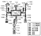
- FIG. 1 is a diagram schematically showing an overall configuration of an automatic analyzer according to a first embodiment. It is a figure which shows one state in operation
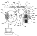
- FIG. 2 is a top view of the overall configuration of the automatic analyzer according to the present embodiment.
- an automatic analyzer 300 includes a sample container rack 302 that stores a plurality of sample containers 301 that hold biological samples such as blood and urine to be analyzed (hereinafter simply referred to as samples), and a sample container rack.
- An incubator disk 309 (a plurality of reaction containers 320 for mixing and reacting a reagent container disk 305 covered with a reagent container disk cover 307 and a sample and an assay reagent) Reaction disk) and incubator from sample container 301 by rotation and vertical movement
- a system reagent bottle containing a system reagent commonly used for a plurality of analysis items can be installed below the work surface of the apparatus.
- the analysis unit 318 has a plurality of reagent discharge units 327 to which a plurality of types of system reagents used in the analysis unit 318 are supplied, and the system reagent is supplied to the reagent discharge unit 327 by a reagent transfer mechanism. .
- this system reagent is simply referred to as “reagent”.
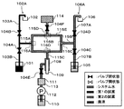
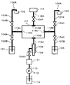
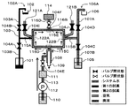
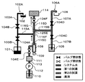
- FIG. 1 is a diagram showing a flow path configuration of a reagent transfer mechanism according to the present embodiment.
- This reagent transfer mechanism is configured below the upper surface of the overall configuration of the automatic analyzer shown in FIG.
- the plurality of reagent discharge units 327 are described as the first discharge unit 102A and the second discharge unit 106A.
- the reagent transfer mechanism is a flow path for sending a first reagent from a reagent container 101 containing a first reagent, which is one of a plurality of reagents, to a first discharge unit 102A corresponding to the first reagent.
- 103A, 103B (first flow path) and the second reagent are sent from the reagent container 105 containing the second reagent different from the first reagent to the second discharge unit 106A corresponding to the second reagent.
- the flow path 107A, 107B (second flow path), the syringe pump 108 that generates a differential pressure in each flow path (including the flow paths 103A, 103B, 107A, 107B) constituting the reagent dispensing mechanism, and discarded
- the adjustment flow path 115E arranged to connect the waste liquid tank 114 to which the waste liquid containing the reagent and the syringe pump 108 are connected, and the middle of the flow paths 103A and 103B (that is, the flow path 103A and the flow path 103B connected in series) Contact
- the first branch part 116A formed by a three-direction flow path in which the portion) and the adjustment flow path 115E are connected to each other at a position different from the first branch part 116A in the adjustment flow path 115E.
- a second branch portion 116C formed of a three-way flow path in which the middle of 107B (that is, a connecting portion between flow path 107A and flow path 107B
- connection flow path 115A which connects the connection part of flow paths 103A and 103B, and the adjustment flow path 115E, and the 2nd branch part 116C is the flow path 107A. , 107B and the adjustment flow path 115E, and the second connection flow path 115B is connected to the adjustment flow path 115E at a position different from the first connection flow path 115A. Configured.
- Two-way valves 104A to 104D for switching between blocking and communicating of the flow path are disposed on the (flow path 107B) and the downstream side (flow path 107A), respectively. When the two-way valves 104A to 104D are in the valve closed state, the flow of the flow paths 103A, 103B, 107A, and 107B is blocked, and in the valve open state, they are communicated.
- the waste liquid tank 114 is connected to the adjustment channel 115E by a channel 115D at a position different from the first and second branch portions 116A and 116C in the adjustment channel 115E.
- a connecting portion between the flow path 115D and the adjustment flow path 115E constitutes a branching portion 116B.
- the flow path 115D is provided with a two-way valve 104F that switches between blocking and communication of the flow path. When the two-way valve 104F is in a valve closed state, the flow of the flow path 115D is blocked and in a valve open state. Is communicated to.
- the syringe pump 108 is connected to the adjustment channel 115E by the channel 115C at a position different from the first and second branch portions 116A and 116C and the branch portion 116B in the adjustment channel 115E.
- a connecting portion between the flow path 115D and the adjustment flow path 115E constitutes a branch portion 116D.
- the syringe pump 108 increases the volume in the syringe pump 108 by pulling the plunger 109 to suck in system water (described later) from the flow path 115C side, and decreases the volume in the syringe pump 108 by pushing the plunger 109. System water (described later) is pushed out toward the flow path 115C.
- the system water container 110 is connected to the syringe pump 108 via a flow path 113 (system water flow path).
- the flow path 113 includes a pump 112 that sends system water from the system water container 110 to the syringe pump 108 through the flow path 113, and a deaeration device 111 that reduces the dissolved oxygen concentration of the system water sent by the pump 112. And a two-way valve 104E that switches between blocking and communicating the flow path 113 between the deaerator 111 and the syringe pump 108. When the two-way valve 104E is closed, the flow of the flow path 113 is blocked, and when the two-way valve 104E is opened, the flow is communicated.
- the adjustment flow path 115E is formed by an annular flow path, and a branching part 116A, a branching part 116B, a branching part 116C, and a branching part 116D are arranged in order in the clockwise direction in FIG. Yes.
- the waste liquid tank 114 and the syringe pump 108 are connected to the adjustment flow path 115E through the flow path 115D
- the syringe pump 108 is connected to the adjustment flow path 115E through the flow path 115C. Connected through.
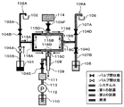
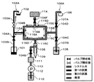
- 3A to 3D are diagrams each showing one state during the operation of the reagent transfer mechanism.
- the reagent transfer mechanism is in the initial state, the plunger 109 of the syringe pump 108 is stopped at the initial position (minimum volume position), and all the two-way valves are closed.
- the flow paths 103A and 103B and the flow path 115A are filled with the first reagent, the flow paths 107A and 107B and the flow path 115B are filled with the second reagent, and the flow paths 115C, 115D and 115E are filled with the system water. Yes.
- the two-way valve 104A is closed, the two-way valve 104B is opened, and the plunger 109 is pushed, so that the first reagent becomes the flow path 103A and the flow path 115A. , 115E and discharged from the first discharge portion 102A to the reaction vessel 102.
- the plunger 109 does not move to the initial position. That is, a part of the first reagent in the annular flow path 115E is left in the flow path 115E.
- the two-way valve 104B is closed, the two-way valves 104E and 104F are opened, the plunger 109 is returned to the initial position, and the system water pressurized by the pump 112 is syringed.
- the solution in the flow paths 115C, 115D, and 115E is sent to the waste liquid tank 114 together with the system water.
- the open / close state of each two-way valve, the position of the plunger, the location of each solution, and the like in the reagent transfer mechanism are in the initial state.
- the case where the first reagent in the reagent container 101 is sent to the reaction container 102 has been described as an example.
- the case where the second reagent in the reagent container 105 is sent to the reaction container 106 is also described. It is the same. That is, in the operations described with reference to FIGS. 3A to 3D, the operations of the two-way valve 104A and the two-way valve 104C are interchanged, and the operations of the two-way valve 104B and the two-way valve 104D are interchanged.
- the second reagent is fed to 106.
- the reagent diluted with the system water by diffusion remains in the flow path 115E (see FIG. 3C).
- the remaining diluted reagent is sent to the waste liquid tank 114 by the system water sent from the pump 112 (see FIG. 3D). Therefore, the flow paths 115C, 115D, and 115E are filled with the system water, and the reagent diluted with the system water is not sent to the flow paths 115A and the flow paths 103A and 103B. Further, the reagent does not remain in the flow path 115E. Therefore, the diluted reagent is not sent to the reaction vessel 102.
- the dispensing operation is performed on the second reagent after the dispensing operation (FIGS. 3A to 3D) is performed on the first reagent. Even if it performs, a 1st reagent and a 2nd reagent do not mix.
- a dispenser for dispensing a reagent to a sample in a reaction container is provided, and a multiple switching valve is provided between a discharge channel of a syringe and each retraction tube. Some of them have a function of selectively moving one of them, and a plurality of reagents are individually moved from one to a liquid delivery destination using one syringe.
- a multiple switching valve having a complicated shape and an expensive shape is used.
- a dispensing device that quantifies or qualitatively analyzes components such as blood and urine, and discharges a plurality of reagents from different reagent discharge nozzles with a single syringe.
- the check valve connected to the reagent bottle and the other check valve connected to the discharge nozzle are connected with a T-shaped tube, and a single syringe is connected to the third branch of the T-shaped tube with a pipe and a branched tube.
- Some of the reagent flow paths are connected to a branch pipe through a solenoid valve as a valve.
- the first reagent is sent from the reagent container 101 containing the first reagent, which is one of the plurality of reagents, to the first ejection unit 102A corresponding to the first reagent.
- the flow paths 103A and 107B and the flow paths 107A and 107B for sending the second reagent from the reagent container 105 containing the second reagent different from the first reagent to the second discharge unit 106A corresponding to the second reagent A syringe pump 108 that generates a differential pressure in the flow paths 103A, 103B, 107A, and 107B, a waste liquid tank 114 to which a waste liquid containing a reagent to be discarded is sent, and an adjustment flow path that is arranged to connect the syringe pump 108 115E, a first branch part 116A formed by three or more flow paths in which the middle of the flow paths 103A and 103B and the adjustment flow path 115E are
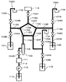
- This modification is formed so that the inner diameter of the adjustment channel (the cross-sectional area of the channel) is smaller than that of other channels.
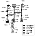
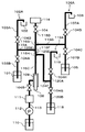
- FIG. 4 is a diagram showing a flow path configuration of the reagent transfer mechanism according to this modification.
- the same members as those in the first embodiment are denoted by the same reference numerals, and description thereof is omitted.
- the reagent transport mechanism is a flow path for sending the first reagent from the reagent container 101 containing the first reagent, which is one of the plurality of reagents, to the first discharge unit 102 ⁇ / b> A corresponding to the first reagent.
- 103A, 103B (first flow path) and the second reagent are sent from the reagent container 105 containing the second reagent different from the first reagent to the second discharge unit 106A corresponding to the second reagent.
- the syringe pump 108 that generates a differential pressure in the flow paths 107A and 107B (second flow path), each flow path (including the flow paths 103A, 103B, 107A, and 107B) constituting the reagent transfer mechanism, and the discarded reagent
- the adjustment flow path 117 disposed so as to connect the waste liquid tank 114 to which the waste liquid containing the liquid and the syringe pump 108 are connected, and the middle of the flow paths 103A and 103B (that is, the flow paths 103A and 103B connected in series) Connection )
- the adjustment channel 115E are connected to each other at a position different from the first branch part 116A formed in the three-direction channel and the first branch part 116A in the adjustment channel 117.
- the inner diameter (cross-sectional area of the flow path) of the adjustment flow path 117 is formed to be smaller than other flow paths such as the flow paths 115A and 115B.
- the flow path 117 having a reduced inner diameter is installed, the area of the interface between the reagent and the system water can be reduced as compared with the first embodiment, and the diffusion of the reagent into the system water can be reduced. Further suppression can be achieved.
- the types of reagents that can be fed are increased by adding reagent containers, discharge sections, flow paths, and the like to the first embodiment.
- FIG. 5 is a diagram showing a flow path configuration of the reagent transfer mechanism according to this modification.
- the same members as those in the first embodiment are denoted by the same reference numerals, and description thereof is omitted.
- the reagent transport mechanism is a flow path for sending the first reagent from the reagent container 101 containing the first reagent, which is one of the plurality of reagents, to the first discharge unit 102 ⁇ / b> A corresponding to the first reagent.
- 103A, 103B (first flow path) and the second reagent are sent from the reagent container 105 containing the second reagent different from the first reagent to the second discharge unit 106A corresponding to the second reagent.
- the flow path 107A, 107B (second flow path) and the reagent container 118 containing a third reagent different from the first and second reagents are transferred from the reagent container 118 to the third discharge section 119A corresponding to the third reagent.
- 3 generates a differential pressure in the flow paths 120A and 120B (third flow path) for sending the reagent and each flow path (including the flow paths 103A, 103B, 107A, 107B, 120A and 120B) constituting the reagent transfer mechanism.
- the adjustment flow path 124E arranged to connect the waste liquid tank 114 to which the waste liquid is sent and the syringe pump 108, and the middle of the flow paths 103A and 103B (that is, the connection between the flow path 103A and the flow path 103B connected in series)
- a second branch part 116C formed by a three-way flow path in which the middle of 107B (that is, the connecting portion of flow path 107A and flow path 107B connected in series) and adjustment flow path 124E are connected; At a position different from the first and second branch portions 116A and 116B in the path 124E, the middle of the flow paths 120A and 120B (that is, the flow path 120A connected in series) It includes a third branch portion 116E of the road 120B connecting portion) and the adjustment channel 124E is formed in the flow path of the connected 3 direction.
- the 116 A of 1st branch parts have the 1st connection flow path 115A which connects the connection part of the flow paths 103A and 103B, and the adjustment flow path 124E, and the 2nd branch part 116C is the flow path 107A. , 107B and the adjustment channel 124E, and the second connection channel 115B is connected to the adjustment channel 124E at a position different from that of the first connection channel 115A.
- the third branch part 116E is a connection channel that connects the connection portions of the channels 120A and 120B and the adjustment channel 124E, and the first and second connection flows in the adjustment channel 124E.
- the third connecting flow path 124F is connected to a position different from the paths 115A and 115B.
- the first branch section 116A in the flow paths 103A and 103B (flow path 103B) and the downstream side (flow path 103A), and the upstream side (the flow path 107B in relation to the second branch section 116C in the flow paths 107A and 107B. ) And the downstream side (flow path 107A) and the upstream side (flow path 120B) and the downstream side (flow path 120A) with respect to the third branch 116E in the flow paths 120A and 120B, respectively.
- Two-way valves 104A to 104D, 104G, and 104H for switching between shut-off and communication are arranged.
- the waste liquid tank 114 is connected to the adjustment flow path 124E by the flow path 115D at a position different from the first to third branch portions 116A, 116C, 116E in the adjustment flow path 124E.
- a connecting portion between the flow path 115D and the adjustment flow path 124E constitutes a branching portion 116B.
- the flow path 115D is provided with a two-way valve 104F that switches between blocking and communication of the flow path. When the two-way valve 104F is in a valve closed state, the flow of the flow path 115D is blocked and in a valve open state. Is communicated to.
- the syringe pump 108 is connected to the adjustment flow path 124E by the flow path 115C at a position different from the first to third branch portions 116A, 116C, 116E and the branch portion 116B in the adjustment flow path 124E.
- a connecting portion between the flow path 115D and the adjustment flow path 124E constitutes a branch portion 116D.
- the syringe pump 108 pulls the plunger 109 to increase the volume in the syringe pump 108 to suck in system water from the flow path 115C side, and pushes the plunger 109 to decrease the volume in the syringe pump 108 to draw system water. It pushes out to the flow path 115C side.
- the adjustment flow path 124E is formed by an annular flow path, and sequentially branches in the clockwise direction in FIG. 5 along the annular adjustment flow path, the branching part 116A, the branching part 116B, the branching part 116C, the branching part 116E, and the branching part 116D. Is arranged.
- the first reagent in the reagent container 101 can be fed to the reaction container 102 by performing the same operation as in the first embodiment. . That is, in the operations described with reference to FIGS. 3A to 3D of the first embodiment, the same operation as that of the two-way valve 104A is performed, and the same operation as that of the two-way valve 104B is performed.
- One reagent can be sent to the reaction vessel 102. The same applies to the case where the second reagent in the reagent container 105 is sent to the reaction container 106 (or the case where the third reagent in the reagent container 118 is sent to the reaction container 119).
- the operation of the two-way valve 104A and the operation of the two-way valve 104C (or the two-way valve 104G) are interchanged, and the operation of the two-way valve 104B.
- the operation of the two-way valve 104D (or the two-way valve 104H) the second reagent is transferred from the reagent container 105 to the reaction container 106 (or the third reagent is transferred from the reagent container 118 to the reaction container 119). Liquid delivery).
- the types of reagents that can be sent from the reagent container to the reaction container can be increased to three.
- the adjustment flow path 124E and the two-way valve 104F are not installed, but the connection flow paths 115A to 115D and 124F are newly arranged. It is good also as a structure which connects and switches a flow path by a multiple valve.
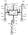
- air insertion channels 121A and 121B for inserting air into the first and second branch portions 116A and 116D in the first embodiment are provided.
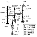
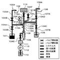
- FIG. 6 is a diagram showing a flow path configuration of the reagent transfer mechanism according to the present embodiment.
- the same members as those in the first embodiment are denoted by the same reference numerals, and description thereof is omitted.
- the reagent transport mechanism is a flow path for sending the first reagent from the reagent container 101 containing the first reagent, which is one of the plurality of reagents, to the first ejection unit 102 ⁇ / b> A corresponding to the first reagent.
- 103A, 103B (first flow path) and the second reagent are sent from the reagent container 105 containing the second reagent different from the first reagent to the second discharge unit 106A corresponding to the second reagent.
- the syringe pump 108 that generates a differential pressure in the flow paths 107A and 107B (second flow path), each flow path (including the flow paths 103A, 103B, 107A, and 107B) constituting the reagent transfer mechanism, and the discarded reagent
- the adjustment flow path 115E arranged so as to connect the waste liquid tank 114 to which the waste liquid containing the liquid and the syringe pump 108 are connected, and the middle of the flow paths 103A and 103B (that is, the flow paths 103A and 103B connected in series) Contact Portion), the first branch part 122A formed by the four-direction flow path to which the adjustment flow path 115E and the air insertion flow path 121A are connected, and the first branch part 122A in the adjustment flow path 115E different from the position , In the middle of the flow paths 107A and 107B (that is, the connecting portion of the flow path 107A and the flow path 107B connected in series), the adjustment flow
- the first branch portion 122A includes a first connection channel 115A that connects the connection portion of the channels 103A and 103B and the adjustment channel 115E
- the second branch portion 122B includes the channel 107A. , 107B and the adjustment flow path 115E, and the second connection flow path 115B is connected to the adjustment flow path 115E at a position different from the first connection flow path 115A. Configured.
- the end of the air insertion channel 121A opposite to the first branch 122A is open to the atmosphere, and a two-way valve 104I is disposed in the air insertion channel 121A.
- the end of the air insertion channel 121B opposite to the second branch portion 122B is open to the atmosphere, and the two-way valve 104J is disposed in the air insertion channel 121B.
- the waste liquid tank 114 is connected to the adjustment channel 115E by the channel 115D at a position different from the first and second branch portions 116A and 116C in the adjustment channel 115E.
- the connecting portion constitutes a branching portion 116B.
- the syringe pump 108 is connected to the adjustment channel 115E by the channel 115C at a position different from the first and second branch parts 122A and 122B and the branch part 116B in the adjustment channel 115E.
- a connecting portion between 115D and adjustment flow path 115E constitutes a branching portion 116D.
- the adjustment flow path 115E is formed by an annular flow path, and a branching part 122A, a branching part 116B, a branching part 122B, and a branching part 116D are arranged in this order in the clockwise direction in FIG. Yes.
- FIGS. 7A to 7D are diagrams respectively showing one state during the operation of the reagent transfer mechanism.
- the plunger 109 of the syringe pump 108 is stopped at the initial position (minimum volume position), and all the two-way valves are closed.
- the flow paths 103A and 103B and the flow path 115A are filled with the first reagent
- the flow paths 107A and 107B and the flow path 115B are filled with the second reagent
- the flow paths 115C, 115D and 115E are filled with the system water.
- the two-way valve 104A is closed, the two-way valve 104B is opened, and the plunger 109 is pushed, so that the first reagent becomes the flow path 103A and the flow path 115A. , 115E and discharged from the first discharge portion 102A to the reaction vessel 102.
- the plunger 109 does not move to the initial position. That is, a part of the first reagent in the annular flow path 115E is left in the flow path 115E.
- the two-way valve 104B is closed, the two-way valves 104E and 104F are opened, the plunger 109 is returned to the initial position, and the system water pressurized by the pump 112 is syringed.
- the solution in the flow paths 115C, 115D, and 115E is sent to the waste liquid tank 114 together with the system water.
- the open / close state of each two-way valve, the position of the plunger, the location of each solution, and the like in the reagent transfer mechanism are in the initial state.
- the case where the first reagent in the reagent container 101 is sent to the reaction container 102 has been described as an example.
- the case where the second reagent in the reagent container 105 is sent to the reaction container 106 is also described. It is the same. That is, in the operations described with reference to FIGS. 7A to 7D, the operations of the two-way valve 104A and the two-way valve 104C and the operations of the two-way valve 104B and the two-way valve 104D are interchanged, and the two-way valve 104I and the two-way valve By switching the operation of 104J, the second reagent is fed from the reagent container 105 to the reaction container 106.
- segmented air is inserted between the reagent and system water in the flow path, it is possible to further suppress the dilution of the reagent with the system water and to suppress the deterioration of the reagent quality caused by dispensing. can do.
- a sensor for measuring the liquid amount may be installed in the reaction container to control the discharge liquid amount of the reagent.
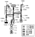
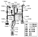
- FIG. 8 is a diagram showing a flow path configuration of the reagent transfer mechanism according to the present embodiment.
- the same members as those in the first embodiment are denoted by the same reference numerals, and description thereof is omitted.
- the reagent transport mechanism is a flow path for sending the first reagent from the reagent container 101 containing the first reagent, which is one of the plurality of reagents, to the first discharge unit 102 ⁇ / b> A corresponding to the first reagent.
- 103A, 103B (first flow path) and the second reagent are sent from the reagent container 105 containing the second reagent different from the first reagent to the second discharge unit 106A corresponding to the second reagent.
- the syringe pump 108 that generates a differential pressure in the flow paths 107A and 107B (second flow path), each flow path (including the flow paths 103A, 103B, 107A, and 107B) constituting the reagent transfer mechanism, and the discarded reagent
- the adjustment flow path 125E disposed so as to connect the waste liquid tank 114 to which the waste liquid containing the liquid and the syringe pump 108 are connected, and the middle of the flow paths 103A and 103B (that is, the flow path 103A and the flow path 103B connected in series) Contact 107A, at a position different from the first branch part 116F formed by a three-way flow path in which the portion) and the adjustment flow path 125E are connected to the first branch part 116F in the adjustment flow path 125E.
- a second branch portion 116G formed of a three-way flow path in which the middle of 107B (that is, the connecting portion between flow path 107A and flow path 107
- the first branch part 116F is configured to include a first connection channel 115A that connects the connection part of the channels 103A and 103B and the adjustment channel 125E, and the second branch part 116G includes the channel 107A. , 107B and the adjustment channel 125E, and a second connection channel 115B connected to the adjustment channel 125E at a position different from the first branch portion 116F. Configured.
- the waste liquid tank 114 is connected to the adjustment flow path 125E by a flow path 115D at one end of the adjustment flow path 125E.
- the syringe pump 108 is connected to the adjustment flow path 125E by the flow path 115C at the other end of the adjustment flow path 125E.
- the adjustment flow path 125E is formed by a single flow path in which the waste liquid tank 114 is connected to one end via the flow path 115D, and the syringe pump 108 is connected to the other end via the flow path 115C.
- a branching part 116F and a branching part 116G are arranged in this order from the syringe pump 108 side.
- the first and second branch portions 116F and 116G are described in the case where they are arranged at positions different from the end portions of the adjustment flow path 125E. Even when the second branch portions 116F and 116G are arranged at the end of the adjustment flow path 125E, a part of the flow paths 115C and 115D plays a part of the function of the adjustment flow path 125E. And can be regarded as a substantially similar configuration.
- the reagent transfer mechanism is in the initial state, the plunger 109 of the syringe pump 108 is stopped at the initial position (minimum volume position), and all the two-way valves are closed.
- the flow paths 103A and 103B and the flow path 115A are filled with the first reagent, the flow paths 107A and 107B and the flow path 115B are filled with the second reagent, and the flow paths 115C, 115D and 125E are filled with the system water. Yes.
- the two-way valve 104A is closed, the two-way valve 104B is opened, and the plunger 109 is pushed, so that the first reagent flows into the flow paths 103A, 115A, 115C. , 125E and discharged from the first discharge portion 102A to the reaction vessel 102.
- the plunger 109 does not move to the initial position. That is, a part of the first reagent in the flow paths 115C and 125E is left in the flow path 125E (or may be the flow path 115C).
- the two-way valve 104B is closed, the two-way valves 104E and 104F are opened, the plunger 109 is returned to the initial position, and the system water pressurized by the pump 112 is syringed.
- the liquid By sending the liquid to the pump 108, the solution in the flow paths 115C, 115D, and 125E is sent to the waste liquid tank 114 together with the system water.
- the open / close state of each two-way valve, the position of the plunger, the location of each solution, and the like in the reagent transfer mechanism are in the initial state.
- the case where the first reagent in the reagent container 101 is sent to the reaction container 102 has been described as an example.
- the case where the second reagent in the reagent container 105 is sent to the reaction container 106 is also described. It is the same. That is, in the operations described with reference to FIGS. 9A to 9D, the operations of the two-way valve 104A and the two-way valve 104C are interchanged, and the operations of the two-way valve 104B and the two-way valve 104D are interchanged.
- the second reagent is fed to 106.
- the types of reagents that can be fed are increased by adding reagent containers, discharge units, flow paths, and the like to the third embodiment.
- FIG. 10 is a diagram showing a flow path configuration of the reagent transfer mechanism according to this modification.
- members similar to those of the third embodiment are denoted by the same reference numerals, and description thereof is omitted.
- first ejection unit 102A first ejection unit 102A, second ejection unit 106A, and third ejection unit
- first ejection unit 102A second ejection unit 106A
- third ejection unit third ejection unit
- the reagent transport mechanism is a flow path for sending the first reagent from the reagent container 101 containing the first reagent, which is one of the plurality of reagents, to the first discharge unit 102A corresponding to the first reagent.
- 103A, 103B (first flow path) and the second reagent are sent from the reagent container 105 containing the second reagent different from the first reagent to the second discharge unit 106A corresponding to the second reagent.
- the flow path 107A, 107B (second flow path) and the reagent container 118 containing a third reagent different from the first and second reagents are transferred from the reagent container 118 to the third discharge section 119A corresponding to the third reagent.
- 3 generates a differential pressure in the flow paths 120A and 120B (third flow path) for sending the reagent and each flow path (including the flow paths 103A, 103B, 107A, 107B, 120A and 120B) constituting the reagent transfer mechanism.
- the adjustment flow path 125E disposed so as to connect the waste liquid tank 114 to which the waste liquid to be contained and the syringe pump 108 are connected, and the middle of the flow paths 103A and 103B (that is, the connection between the flow path 103A and the flow path 103B connected in series) 107A, at a position different from the first branch part 116F formed by the three-way flow path in which the portion) and the adjustment flow path 124E are connected to the first branch part 116F in the adjustment flow path 125E.
- a second branch part 116G formed of a three-way flow path in which the middle of 107B (that is, the connecting portion of flow path 107A and flow path 107B connected in series) and adjustment flow path 125E are connected; At a position different from the first and second branch parts 116F and 116G in the path 125E, the middle of the flow paths 120A and 120B (that is, the flow paths 120A connected in series) It includes a third branch portion 116H which the flow path 120B connecting portion) and the adjustment channel 125E is formed in the flow path of the connected 3 direction.
- the first branch part 116F is configured to include a first connection channel 115A that connects the connection part of the channels 103A and 103B and the adjustment channel 125E
- the second branch part 116G includes the channel 107A. , 107B and the adjustment channel 125E, the second connection channel 115B connected to a position different from the first connection channel 115A in the adjustment channel 125E.
- the third branch portion 116H is a connection channel that connects the connection portions of the channels 120A and 120B and the adjustment channel 125E, and the first and second connection flows in the adjustment channel 125E.
- the third connecting flow path 124F is connected to a position different from the paths 115A and 115B.
- Two-way valves 104A to 104D, 104G, and 104H for switching between blocking and communicating are disposed.
- the waste liquid tank 114 is connected to the adjustment flow path 125E by a flow path 115D at one end of the adjustment flow path 125E.
- the syringe pump 108 is connected to the adjustment flow path 125E by the flow path 115C at the other end of the adjustment flow path 125E.
- the adjustment flow path 125E is formed by a single flow path in which the waste liquid tank 114 is connected to one end via the flow path 115D, and the syringe pump 108 is connected to the other end via the flow path 115C.
- the branch portions 116H and 116F and the branch portion 116G are arranged in this order from the syringe pump 108 side.
- the first to third branch portions 116F, 116G, and 116H are described with reference to the case where the first to third branch portions 116F, 116G, and 116H are arranged at positions different from the end portions of the adjustment flow path 125E. Even when the third branch portions 116F, 116G, and 116H are disposed at the end of the adjustment flow path 125E, a part of the flow paths 115C and 115D bear a part of the function of the adjustment flow path 125E. It can be considered that the configuration is substantially the same as the modified example.
- the types of reagents that can be sent from the reagent container to the reaction container can be increased to three.
- air insertion passages 121A and 121B for inserting air into the first and second branch portions 116F and 116G in the third embodiment are provided.
- FIG. 11 is a diagram showing a flow path configuration of the reagent transfer mechanism according to the present embodiment.
- members similar to those of the third embodiment are denoted by the same reference numerals, and description thereof is omitted.
- the reagent transport mechanism is a flow path for sending the first reagent from the reagent container 101 containing the first reagent, which is one of the plurality of reagents, to the first ejection unit 102A corresponding to the first reagent.
- 103A, 103B (first flow path) and the second reagent are sent from the reagent container 105 containing the second reagent different from the first reagent to the second discharge unit 106A corresponding to the second reagent.
- the syringe pump 108 that generates a differential pressure in the flow paths 107A and 107B (second flow path), each flow path (including the flow paths 103A, 103B, 107A, and 107B) constituting the reagent transfer mechanism, and the discarded reagent
- the adjustment flow path 125E disposed so as to connect the waste liquid tank 114 to which the waste liquid containing the liquid and the syringe pump 108 are connected, and the middle of the flow paths 103A and 103B (that is, the flow path 103A and the flow path 103B connected in series)
- the first branch part 132A formed by a four-direction flow path to which the adjustment flow path 125E and the air insertion flow path 121A are connected, and the first branch part 132A in the adjustment flow path 125E are different.
- the channel 107A, 107B is in the middle (that is, the connecting portion between the channel 107A and the channel 107B connected in series), the adjustment channel 125E, and the air insertion channel 121B. And a second branch portion 132B to be formed.
- the first branch portion 132A includes a first connection channel 115A that connects the connection portions of the channels 103A and 103B and the adjustment channel 125E
- the second branch portion 132B includes the channel 107A. , 107B and the adjustment channel 125E, the second connection channel 115B connected to a position different from the first connection channel 115A in the adjustment channel 125E. Configured.
- the end of the air insertion channel 121A opposite to the first branch portion 132A is open to the atmosphere, and a two-way valve 104I is disposed in the air insertion channel 121A.
- the end of the air insertion channel 121B opposite to the second branch 132B is open to the atmosphere, and the two-way valve 104J is disposed in the air insertion channel 121B.
- the waste liquid tank 114 is connected to the adjustment flow path 125E by a flow path 115D at one end of the adjustment flow path 125E.
- the syringe pump 108 is connected to the adjustment flow path 125E by the flow path 115C at the other end of the adjustment flow path 125E.
- the adjustment flow path 125E is formed by a single flow path in which the waste liquid tank 114 is connected to one end via the flow path 115D, and the syringe pump 108 is connected to the other end via the flow path 115C.
- a branching part 132A and a branching part 132B are arranged in this order from the syringe pump 108 side.
- 12A to 12D are diagrams showing one state during the operation of the reagent transfer mechanism.
- the plunger 109 of the syringe pump 108 is stopped at the initial position (minimum volume position), and all the two-way valves are closed.
- the flow paths 103A and 103B and the flow path 115A are filled with the first reagent
- the flow paths 107A and 107B and the flow path 115B are filled with the second reagent
- the flow paths 115C, 115D and 125E are filled with the system water.
- the two-way valve 104I is closed, and only the two-way valve 104A is opened, and the plunger 109 is pulled to allow the first reagent to flow through the flow paths 103B, 115A and Liquid is fed to a part of the flow path 125E.
- the two-way valve 104A is closed, the two-way valve 104B is opened, and the plunger 109 is pushed, so that the first reagent becomes the flow path 103A and the flow path 115A. , 125E and discharged from the first discharge portion 102A to the reaction vessel 102.
- the plunger 109 does not move to the initial position. That is, a part of the first reagent in the flow paths 115C and 125E is left in the flow path 125E (or may be the flow path 115C).
- the two-way valve 104B is closed, the two-way valves 104E and 104F are opened, the plunger 109 is returned to the initial position, and the system water pressurized by the pump 112 is syringed.
- the liquid By sending the liquid to the pump 108, the solution in the flow paths 115C, 115D, and 125E is sent to the waste liquid tank 114 together with the system water.
- the open / close state of each two-way valve, the position of the plunger, the location of each solution, and the like in the reagent transfer mechanism are in the initial state.
- the case where the first reagent in the reagent container 101 is sent to the reaction container 102 has been described as an example.
- the case where the second reagent in the reagent container 105 is sent to the reaction container 106 is also described. It is the same. That is, in the operations described with reference to FIGS. 12A to 12D, the operations of the two-way valve 104A and the two-way valve 104C and the operations of the two-way valve 104B and the two-way valve 104D are interchanged, and By switching the operation of 104J, the second reagent is fed from the reagent container 105 to the reaction container 106.
- segmented air is inserted between the reagent and system water in the flow path, it is possible to further suppress the dilution of the reagent with the system water and to suppress the deterioration of the reagent quality caused by dispensing. can do.
- an air insertion flow path may be newly provided in the branch portions 116F, 116G, and 116H of the modified example of the third embodiment.
- Adjustment channel 116A to 116H, 122A, 122B, 132A, 132B ... Branching part, 121A, 121B ... Air insertion channel, 300 ... Automatic analysis Equipment 301 ... Sample container 302 ... Sample container rack 303 ... Rack transport line 304 ... Reagent 305 ... Reagent container disk, 307 ... Reagent container disk cover, 309 ... Incubator disk, 310 ... Sample dispensing nozzle, 311 ... Reagent dispensing nozzle, 312 ... Reaction container / sample dispensing chip storage unit, 313 ... Reaction container Sample dispensing tip storage unit, 314 ... reaction liquid stirring mechanism, 315 ... disposal port, 316 ...
Landscapes
- Physics & Mathematics (AREA)
- Health & Medical Sciences (AREA)
- Life Sciences & Earth Sciences (AREA)
- Chemical & Material Sciences (AREA)
- Analytical Chemistry (AREA)
- Biochemistry (AREA)
- General Health & Medical Sciences (AREA)
- General Physics & Mathematics (AREA)
- Immunology (AREA)
- Pathology (AREA)
- Automatic Analysis And Handling Materials Therefor (AREA)
Applications Claiming Priority (2)
| Application Number | Priority Date | Filing Date | Title |
|---|---|---|---|
| JP2017033227A JP6611365B2 (ja) | 2017-02-24 | 2017-02-24 | 自動分析装置 |
| JP2017-033227 | 2017-02-24 |
Publications (1)
| Publication Number | Publication Date |
|---|---|
| WO2018154978A1 true WO2018154978A1 (ja) | 2018-08-30 |
Family
ID=63252581
Family Applications (1)
| Application Number | Title | Priority Date | Filing Date |
|---|---|---|---|
| PCT/JP2018/000066 Ceased WO2018154978A1 (ja) | 2017-02-24 | 2018-01-05 | 自動分析装置 |
Country Status (2)
| Country | Link |
|---|---|
| JP (1) | JP6611365B2 (enExample) |
| WO (1) | WO2018154978A1 (enExample) |
Cited By (1)
| Publication number | Priority date | Publication date | Assignee | Title |
|---|---|---|---|---|
| CN115479827A (zh) * | 2021-12-15 | 2022-12-16 | 深圳市瑞图生物技术有限公司 | 液基后处理装置及液基样本处理设备 |
Citations (4)
| Publication number | Priority date | Publication date | Assignee | Title |
|---|---|---|---|---|
| JPS50140368A (enExample) * | 1974-04-30 | 1975-11-11 | ||
| JPH0381559U (enExample) * | 1989-12-11 | 1991-08-20 | ||
| JP2004170156A (ja) * | 2002-11-18 | 2004-06-17 | Sysmex Corp | 試料分析装置とそれに用いる液体吸引管 |
| JP2011033426A (ja) * | 2009-07-31 | 2011-02-17 | Hitachi High-Technologies Corp | 自動分析装置および自動分析装置の制御方法 |
Family Cites Families (2)
| Publication number | Priority date | Publication date | Assignee | Title |
|---|---|---|---|---|
| JPH0571767U (ja) * | 1992-02-28 | 1993-09-28 | 株式会社島津製作所 | 試料の分注希釈装置 |
| EP2878954A1 (en) * | 2013-11-28 | 2015-06-03 | F. Hoffmann-La Roche AG | Pipetting method and system |
-
2017
- 2017-02-24 JP JP2017033227A patent/JP6611365B2/ja active Active
-
2018
- 2018-01-05 WO PCT/JP2018/000066 patent/WO2018154978A1/ja not_active Ceased
Patent Citations (4)
| Publication number | Priority date | Publication date | Assignee | Title |
|---|---|---|---|---|
| JPS50140368A (enExample) * | 1974-04-30 | 1975-11-11 | ||
| JPH0381559U (enExample) * | 1989-12-11 | 1991-08-20 | ||
| JP2004170156A (ja) * | 2002-11-18 | 2004-06-17 | Sysmex Corp | 試料分析装置とそれに用いる液体吸引管 |
| JP2011033426A (ja) * | 2009-07-31 | 2011-02-17 | Hitachi High-Technologies Corp | 自動分析装置および自動分析装置の制御方法 |
Cited By (1)
| Publication number | Priority date | Publication date | Assignee | Title |
|---|---|---|---|---|
| CN115479827A (zh) * | 2021-12-15 | 2022-12-16 | 深圳市瑞图生物技术有限公司 | 液基后处理装置及液基样本处理设备 |
Also Published As
| Publication number | Publication date |
|---|---|
| JP2018138879A (ja) | 2018-09-06 |
| JP6611365B2 (ja) | 2019-11-27 |
Similar Documents
| Publication | Publication Date | Title |
|---|---|---|
| JP6647288B2 (ja) | 自動分析装置及び方法 | |
| JP6269829B2 (ja) | 液体試料導入装置 | |
| US20140037503A1 (en) | Automatic analyzer | |
| CN101960311A (zh) | 分析装置用输送装置、分析装置、分析系统、以及输送装置用的连接器 | |
| JP2006242720A (ja) | 自動試料導入装置 | |
| US9815052B2 (en) | Fluid dispensing device including a valve assembly fluidically coupled to a first and second inlet, and to a first and second outlet | |
| EP3572816B1 (en) | Automated analyzer, liquid discharge method for automated analyzer, and three-way solenoid valve | |
| JP2022549251A (ja) | 流体輸送システム、方法、並びにそれを適用する流体使用装置 | |
| US20190018029A1 (en) | Automated Analysis Device and Automated Analysis Method | |
| JP2010505128A5 (enExample) | ||
| JP6611365B2 (ja) | 自動分析装置 | |
| US20110146389A1 (en) | Continuous flow pump | |
| JP2011033426A (ja) | 自動分析装置および自動分析装置の制御方法 | |
| US20260071938A1 (en) | Sampling system with a replaceable cassette assembly and methods of using the same | |
| US7343925B2 (en) | Device and method for extracting liquid samples | |
| JP5121333B2 (ja) | 分注装置 | |
| JP6284312B2 (ja) | 試料導入方法および試料導入装置 | |
| WO2016136290A1 (ja) | 自動分析装置および液体容器 | |
| JP2019095268A (ja) | 分注用シリンジポンプ及びそれを備えた自動分析装置 | |
| JP3164406B2 (ja) | 選択的液体分注装置および選択的液体分注方法 | |
| US20240345122A1 (en) | Fluid transfer in a biological analysis system | |
| JPS5887462A (ja) | 液体試料分析装置 | |
| KR20250123671A (ko) | 라이브러리 준비 시스템 및 연관된 방법 | |
| KR20250024039A (ko) | 자동화된 인라인 나노입자 표준 물질 추가 | |
| JPS61200472A (ja) | 試薬液の分注方法 |
Legal Events
| Date | Code | Title | Description |
|---|---|---|---|
| 121 | Ep: the epo has been informed by wipo that ep was designated in this application |
Ref document number: 18757528 Country of ref document: EP Kind code of ref document: A1 |
|
| NENP | Non-entry into the national phase |
Ref country code: DE |
|
| 122 | Ep: pct application non-entry in european phase |
Ref document number: 18757528 Country of ref document: EP Kind code of ref document: A1 |