WO2018154807A1 - 蓋開閉機構、空気調和機 - Google Patents
蓋開閉機構、空気調和機 Download PDFInfo
- Publication number
- WO2018154807A1 WO2018154807A1 PCT/JP2017/025221 JP2017025221W WO2018154807A1 WO 2018154807 A1 WO2018154807 A1 WO 2018154807A1 JP 2017025221 W JP2017025221 W JP 2017025221W WO 2018154807 A1 WO2018154807 A1 WO 2018154807A1
- Authority
- WO
- WIPO (PCT)
- Prior art keywords
- lid
- front panel
- bearing
- shaft
- rotating shaft
- Prior art date
- Legal status (The legal status is an assumption and is not a legal conclusion. Google has not performed a legal analysis and makes no representation as to the accuracy of the status listed.)
- Ceased
Links
Images







Classifications
-
- F—MECHANICAL ENGINEERING; LIGHTING; HEATING; WEAPONS; BLASTING
- F24—HEATING; RANGES; VENTILATING
- F24F—AIR-CONDITIONING; AIR-HUMIDIFICATION; VENTILATION; USE OF AIR CURRENTS FOR SCREENING
- F24F13/00—Details common to, or for air-conditioning, air-humidification, ventilation or use of air currents for screening
- F24F13/20—Casings or covers
Definitions
- the present invention relates to a lid opening / closing mechanism for opening and closing the lid.
- General air conditioners open the front panel provided on the front of the indoor unit in order to remove the filter of the indoor unit. At this time, the front panel is held in an open state at a certain angle with respect to the indoor unit body. In the air conditioner, the front panel is removed from the indoor unit body in order to remove the blower fan, fan motor, and the like in the indoor unit.
- Patent Document 1 includes a front panel that can be opened and closed by a support shaft that is detachably supported in a shaft hole of a main body case of an indoor unit, and the front panel is opened at a certain angle with respect to the main body case.
- An air conditioner in which a front panel is detachable from the main body case is disclosed.
- JP-A-8-135994 (published May 13, 1996)
- Patent Document 1 in order to maintain the open state of the front panel and make it removable, the protrusion provided on the arm of the front panel needs to run over the plurality of protrusions provided on the main body case. . For this reason, in order to hold
- the frictional force between the protrusions will be reduced, making it easier to attach, remove and open / close the front panel, and to suppress the generation of noise when attaching, removing and opening / closing the front panel.
- One aspect of the present invention is a lid opening / closing mechanism that can smoothly attach, remove, and open / close the front panel to / from the main body case, and can suppress the generation of noise due to the attachment, removal, and opening / closing of the front panel to the main body case.
- the purpose is to provide.
- a lid opening / closing mechanism is a lid opening / closing mechanism that opens and closes a lid that is detachably attached to a housing, and a support member that supports the lid;
- a rotating shaft provided on the support member, rotatably supported by a bearing portion formed on the housing, and capable of being detached from the bearing portion when rotated by a predetermined angle, and provided on the support member.
- FIG. 1 It is a schematic perspective view of the air conditioner which concerns on Embodiment 1 of this invention. It is a schematic sectional drawing which shows the state which the front panel of the air conditioner shown in FIG. 1 closed. It is a schematic sectional drawing which shows the state which the front panel of the air conditioner shown in FIG. 1 opened to the position which can attach or detach a dust box. It is a schematic sectional drawing which shows the state which the front panel of the air conditioner shown in FIG. 1 opened to the position which can attach or detach the said front panel. It is a figure for demonstrating operation
- Embodiment 1 Hereinafter, embodiments of the present invention will be described as follows.
- an example of an indoor unit of a separate type air conditioner that is attached to a wall surface of a room will be described as an example to which the lid opening / closing mechanism of the present invention is applied.
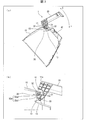
- FIG. 1 is a perspective view showing an appearance of an indoor unit 1 of an air conditioner (air conditioner), where (a) shows a state in which a front panel (lid) 20 is closed, and (b) shows that a front panel 20 is opened. Indicates the state.
- air conditioner air conditioner
- the indoor unit 1 supports the operation of the main body (housing) 10, the front panel 20 covering the front surface of the main body 10, and the front panel 20 so as to open and close the front surface 10a of the main body 10. And a lid opening / closing mechanism 30.
- the main body 10 includes various members that are naturally provided in the air conditioner indoor unit 1 such as a blower fan (for example, a crossflow fan or a propeller fan) and a heat exchanger. In the present embodiment, description of these various members is omitted.
- a blower fan for example, a crossflow fan or a propeller fan
- a heat exchanger for example, a heat exchanger
- the main body 10 is provided with a dust box 40 on the front surface.
- the dust box 40 is one of the components of the filter cleaning device provided in the main body 10.
- the filter cleaning device removes dust such as dust and dust adhering to the filter and accumulates it in the dust box 40.
- the dust box 40 is detachably installed from the main body 10.
- the front panel 20 is in a closed state in which the front surface of the main body 10 is closed as shown in FIG. 1A and an open state in which the front surface 10a of the main body 10 is opened as shown in FIG.
- the main body 10 is rotatably provided.
- the front panel 20 is in the open state shown in FIG. 1B, the user attaches / detaches the dust box 40 from the front surface 10 a of the main body 10.
- the filter can also be attached and detached with the dust box 40 removed.
- the front panel 20 is rotated by a predetermined angle in the opening direction from the open state shown in FIG. 1B to a further open state, that is, when the front panel 20 is in the closed state.
- the front panel 20 can be attached to and detached from the main body 10. That is, the front panel 20 is in a three-stage state: a closed state shown in FIG. 1A, an open state shown in FIG. 1B, and a state in which the opened front panel 20 is detachable. It is configured.
- the above-described three-stage opening / closing of the front panel 20 is realized by the lid opening / closing mechanism 30.
- the opening angle of the front panel 20 with respect to the main body 10 is approximately 90 ° in the state shown in FIG.
- the opening angle is not limited to 90 °, and any angle is acceptable as long as the front panel 20 is opened to such an extent that the user can perform maintenance such as attachment / detachment of the dust box 40 in the main body 10. May be.
- the opening angle when attaching / detaching the front panel 20 may be a little larger than the opening angle shown in FIG. 1 (b), and any angle can be used as long as the front panel 20 can be attached / detached. Also good.
- FIG. 2 is a view for explaining the operation of the lid opening / closing mechanism 30 when the front panel 20 is in the closed position
- FIG. 2A is a view showing a cross section of the main body 10.
- FIG. 3 is a view for explaining the operation of the lid opening / closing mechanism 30 when the front panel 20 is opened to a position where the dust box 40 can be attached and detached.
- FIG. It is a figure shown, (b) is the enlarged view to which the principal part of (a) was expanded.
- FIG. 4 is a diagram for explaining the operation of the lid opening / closing mechanism 30 when the front panel 20 is opened to a position where the front panel 20 can be attached and detached. It is a figure which shows a cross section, (b) is the enlarged view to which the principal part of (a) was expanded.
- the front panel 20 is supported by the lid opening / closing mechanism 30 so as to be rotatable in directions of arrows X and Y about a rotation shaft 32 (described later). That is, the front panel 20 rotates in the direction of the arrow X from the closed position (closed position) shown in FIG. 2A and opens a little, and the dust box 40 shown in FIG. A state in which the front panel 20 shown in FIG. 4A is detachably supported by being temporarily fixed and supported at a position (fixed support position) in which it is possible, further rotated in the direction of the arrow X, and further opened. Rotate to the position (separable position). Further, the front panel 20 rotates from the state shown in FIG.
- the closed state means a state in which the front surface of the main body 10 of the indoor unit 1 is closed by the front panel 20. Normally, air conditioning such as cooling and heating of the air conditioner is performed when the front panel 20 is closed.
- the state in which the dust box 40 is detachable means a state in which the front panel 20 is opened to a state in which the dust box 40 and the filter installed in the main body 10 can be attached to and detached from the main body 10.
- the state in which the front panel 20 can be attached / detached refers to a state in which the front panel 20 is further opened than the state in which the dust box 40 can be attached / detached, and a state in which the front panel 20 can be attached to / detached from the body 10.
- the lid opening / closing mechanism 30 is a mechanism for rotatably supporting the front panel 20 with respect to the main body 10 as described above, and includes an arm (support member) 31 that supports the front panel 20, and an arm 31. Provided and rotatably supported by a bearing part (bearing upper part) 11 and a bearing part (bearing lower part) 12 formed in the main body 10, and can be detached from the bearing parts 11 and 12 when rotated by a predetermined angle. A cylindrical rotary shaft 32 and an arm 31 are provided. While the rotary shaft 32 rotates by the predetermined angle, the front panel 20 rotates while being engaged with the stopper receiving portion 13 formed in the main body 10. And a stopper (fixed support shaft) 33 for fixing and supporting at a predetermined angle.
- the bearing part (bearing upper part) 11 and the bearing part (bearing lower part) 12 are arranged so as to face each other and support the rotary shaft 32 so as to be pivotable from above and below.
- Each of the bearing portions 11 and 12 is formed of an elastic member, for example, a resin.
- the bearing portion 12 is configured to bend, and the bearing portion 11 is configured not to be bent (has a strength that does not bend at least when the rotary shaft 32 is attached / detached).
- the bearing portion 11 has an arcuate shaft upper support surface that receives the outer peripheral surface 32 of the cylindrical rotation shaft.
- the shaft upper support surface is located on the front side and above the center of the rotary shaft 32 from directly above the rotary shaft 32 (see FIG. 2B). However, it is located over the tangent line directly above the rotation shaft 32).
- the front means a direction in which the front panel 20 is removed from the main body 10. Further, upward refers to a direction opposite to the vertical direction (the direction of gravity) in the main body 10.
- the bearing portion 12 has an arc-shaped lower shaft support surface that receives the outer peripheral surface 32 of the cylindrical rotation shaft.
- the lower shaft support surface is located directly below the rotary shaft 32 and below the center of the rotary shaft 32 (see FIG. 2B). However, it is located over a tangent line directly below the rotating shaft 32).
- the rotating shaft 32 will be in the state closely_contact
- the bearing portions 11 and 12 are projections for restricting movement of the rotary shaft 32 in the direction of taking out the front panel 20 (direction of taking out the front panel 20 from the main body 10) on the surface that supports the rotary shaft 32, respectively.
- a portion (first protrusion) 11a and a protrusion (second protrusion) 12a are formed.
- the protruding portion 11a is an arc-shaped convex portion that continues from the front end portion of the shaft upper support surface to the front side.
- the protrusion 12a has a surface extending in the horizontal direction from the front end portion of the lower-axis support surface, and includes a surface extending downward from the front end portion of the surface.
- the bearing portion 11 does not bend and the bearing portion 12 is bent due to the movement of the rotary shaft 32.
- the said rotating shaft 32 gets over the protrusion parts 11a and 12a.
- the width of the guide space on the right side of the projections 11a and 12a is wider than the width in the vertical direction of the bearings 11 and 12 on the left side of the projections 11a and 12a.
- the distance (height) D1 from the vertex of the protrusion 11a to the line passing through the axis center x and the distance (height) D2 from the vertex of the protrusion 12a to the line passing through the axis center x are the distance D2. Is larger (see FIG. 6).
- the rotating shaft 32 is cylindrical as shown in FIG. 2B, and a part of the outer peripheral surface 32a is flat. This flat surface is referred to as a D-cut surface 32a1. The remaining surface of the outer peripheral surface 32a is defined as a peripheral surface 32a2.
- the rotating shaft 32 is rotated so that the D-cut surface 32a1 is positioned to face the bearing portion 12 when the front panel 20 is detached as shown in FIG. 4B. Yes. Thereby, the rotating shaft 32 becomes easy to get over the protrusion part 12a of the bearing part 12 by D cut surface 32a1.
- the D-cut surface 32a1 of the rotating shaft 32 is not provided by providing the bearing 11 with spring property (having strength that does not bend at least when the rotating shaft 32 is attached / detached) and by providing the bearing portion 12 with spring property.
- the rotary shaft 32 can be removed from the bearing portions 11 and 12 by pushing down the bearing portion 12 downward.
- the rotating shaft 32 is such that the outer peripheral surface 32a of the outer peripheral surface 32a other than the D-cut surface 32a1 is always in close contact with the bearing portion 11, the rotating shaft 32 can be easily detached from the bearing portions 11 and 12. There is no such thing.
- the rotating shaft 32 is configured such that the outer peripheral surface 32a is in close contact with both the bearing portions 11 and 12, and thus the rotation. The shaft 32 is more difficult to be removed from the bearing portions 11 and 12.
- the stopper 33 is made of a member having a substantially circular cross section like the rotary shaft 32, and the outer peripheral surface 33 a can be in close contact with the concave engaging surface of the stopper receiving portion 13. That is, as shown in FIGS. 3A and 3B, the stopper 33 comes into close contact with the engaging surface of the stopper receiving portion 13 when the dust box is removed. Accordingly, the rotation of the rotating shaft 32, that is, the rotation of the front panel 20, can be restricted, and the holding force for holding the open state of the front panel 20 at a predetermined position can be increased.
- the stopper receiving portion 13 engages with a stopper 33 formed on the arm 31 in a state where the dust box 40 is detachable as shown in FIG.
- the stopper receiving portion 13 is in the closed state shown in FIG. 2B and the front panel 20 shown in FIG. 4B is detachable, the stopper receiving portion 13 is disengaged from the stopper 33. Become.
- FIG. 5 is a diagram for explaining the operation of the lid opening / closing mechanism 30 in a state where the dust box 40 shown in FIG.
- the engaging position where the stopper 33 is engaged by the stopper receiving portion 13 is shifted from the straight line (axis) extending in the vertical direction (the direction of gravity) from the rotating shaft 32 in the removing direction (front) of the front panel 20.
- the engagement position is a position where a straight line extending in the vertical direction from the rotation shaft 32 and a straight line extending from the rotation shaft 32 to the stopper 33 are separated by an angle ⁇ .
- the angle ⁇ is preferably 15 °, but is not limited to this and may be larger than 0 °. That is, the engagement position may be in front of the straight line extending in the vertical direction from the rotation shaft 32 (in the direction of removing the front panel 20). Further, when the stopper 33 is in the engagement position, the outer peripheral surface 32 a of the rotating shaft 32 is in close contact with the bearing portion 11.
- the stopper 33 rotates in the direction of arrow A with the rotation shaft 32 as a fulcrum.
- the engagement between the outer peripheral surface 33a of the stopper 33 and the contact surface 13a of the stopper receiving portion 13 is easily released.
- the stopper 33 is in the engaged position, since the outer peripheral surface 32a of the rotating shaft 32 is in close contact with the bearing portion 11, when the front panel 20 is closed, the rotating shaft 32 is used as a fulcrum for the stopper 33. Rotates in the direction of arrow B.
- the engaging force between the stopper 33 and the stopper receiving portion 13 is increased, and the rotation shaft 32 that is a fulcrum tends to move in the direction of arrow C.
- the fulcrum does not move from the rotating shaft 32.
- the front panel 20 can be closed smoothly.
- the engagement force between the stopper 33 and the stopper receiving portion 13 can be freely set by changing the angle ⁇ .
- the rotary shaft 32 is sandwiched in a state of being in close contact with the bearing portions 11 and 12, and thus the front panel 20. Can be securely fixed. Further, even if the front panel 20 is further forcibly opened from FIGS. 4A and 4B, if the front panel 20 is rotated in the direction of the arrow X beyond the state shown in FIGS. Since 20 is configured to be easily removable, the opening / closing mechanism of the front panel 20 is not damaged.
- FIG. 6 is a diagram for explaining C.
- FIG. 7 is a diagram for explaining the adjustment of the holding strength of the front panel 20.
- FIG. 8 is a diagram for explaining the adjustment of the slit position height of the bearing portion 12 and the adjustment of the slit position height of the stopper 13.
- FIG. 9 is an enlarged view of the main part H of FIG.
- the distance G from the bottom surface of the contact surface 13a of the stopper receiving portion 13 to the top portion 13b and the slit By adjusting the position height F, the engagement force and engagement hardness of the stopper 33 can be easily adjusted.
- the height E of the slit 101 provided in the bearing portion 12 and the height F of the slit 102 provided in the stopper receiving portion 13 are adjusted. If E and F are made high, the bearing part 12 and the stopper receiving part 13 will bend easily, and the removal strength of the front panel 20 will become weak. On the contrary, if E and F are made low, the bearing part 12 and the stopper receiving part 13 become difficult to bend, so that the removal strength of the front panel 20 is increased.
- ribs 103 and 103 are provided on the back surface of the stopper receiving portion 13, and the height of the ribs 103 and 103 is adjusted. Good. In this case, the higher the height of the ribs 103, 103, the more difficult the stopper receiving portion 13 bends, so that the strength of removing the front panel 20 increases.
- FIG. 11 is a view for explaining the operation of the dust box removal state in the lid opening / closing mechanism 130 according to the present embodiment.
- the lid opening / closing mechanism 130 has substantially the same configuration as the lid opening / closing mechanism 30 of the first embodiment, and the difference is the cross-sectional shape of the rotating shaft 132.
- the cross-sectional shape of the rotating shaft 132 is a circular shape without a D-cut surface, as shown in FIG. That is, the rotating shaft 132 has a substantially circular cross section as described above, and the rotating shaft 132 is disposed on the bearing surface (the shaft upper support surface, the shaft lower support surface) of the rotation shaft 132 of the bearing portions 11 and 12.
- the outer peripheral surface (rotating surface) is formed into a shape that can be in close contact.
- the stopper 133 has the same shape as the stopper 33 of the lid opening / closing mechanism 30 of the above embodiment, and has a circular cross-sectional shape.
- the outer peripheral surface of the rotating shaft 132 is always in close contact with the bearing portions 11 and 12, so that even if the front panel 20 is removed, the rotating shaft Since there is no D-cut surface in 132, the adhesion between the rotary shaft 132 and the bearing portion 12 is increased, and the punching strength of the front panel 20 can be increased. That is, the front panel 20 can be prevented from easily falling off the main body 10.
- FIG. 12 is a view for explaining the operation of the dust box removal state in the lid opening / closing mechanism 230 according to the present embodiment.
- the lid opening / closing mechanism 230 has substantially the same configuration as the lid opening / closing mechanism 30 of the first embodiment, and is different in the shape of the stopper 233.
- the cross-sectional shape of the stopper 233 is a shape having a D-cut surface as shown in FIG.
- the rotating shaft 232 is the same circular shape as the rotating shaft 32 of the lid
- the contact surface of the stopper receiving portion 213 with the stopper 233 has a planar shape. Therefore, when the dust box of the front panel 20 is removed, the D-cut surface of the stopper 233 and the contact surface of the stopper receiving portion 213 can face each other and can be brought into close contact with each other.
- the opening / closing angle of the front panel 20 can be kept constant by adjusting the inclination of the contact surface when the D-cut surface of the stopper 233 and the contact surface of the stopper receiving portion 213 are in close contact.
- the front surface is adjusted by adjusting the distance from the axial center X of the rotating shaft 232 to the D-cut surface and the slit position height in the bearing portion 12 and the stopper receiving portion 13.
- the removal strength (hardness of removal) of the panel 20 can be easily adjusted.
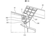
- FIG. 13 is a view for explaining the operation of the dust box removal state in the lid opening / closing mechanism 330 according to the present embodiment.
- the lid opening / closing mechanism 330 has substantially the same configuration as the lid opening / closing mechanism 30 of the first embodiment, and is different in the shapes of the rotating shaft 332 and the stopper 333. As shown in FIG. 13, the rotation shaft 332 has a circular shape without a D-cut surface. The stopper 333 has a D-cut surface as in the stopper 233 of the third embodiment.
- the contact surface of the stopper receiving portion 213 with the stopper 233 has a planar shape.
- the stopper 233 has a flat surface parallel to a direction in which the stopper 233 is detached from the stopper receiving portion 213 on the outer peripheral surface supported by the stopper receiving portion 213 so that the front panel 20 can be detached. In position, it faces the upper surface of the stopper receiving portion 213.
- the stopper 233 and the stopper receiving portion 213 can be brought into close contact with each other.
- the opening / closing angle of the front panel 20 at the fixed support position can be adjusted by adjusting the inclination of the contact surface.
- the opening / closing angle of the front panel 20 can be kept constant by adjusting the inclination of the contact surface when the D-cut surface of the stopper 233 and the contact surface of the stopper receiving portion 213 are in close contact.
- the outer peripheral surface of the rotating shaft 332 is always kept in close contact with the bearing portions 11 and 12. For this reason, even when the front panel 20 is detached, the adhesion between the rotary shaft 332 and the bearing portion 12 is increased by the absence of the D-cut surface on the rotary shaft 332, and the pull-out strength of the front panel 20 can be increased. it can.
- the lid opening / closing mechanism 430 has substantially the same configuration as the lid opening / closing mechanism 30 of the first embodiment, and the difference is the shape of the stopper 433. As shown in FIG. 14, the stopper 433 is formed with ribs 433 a at portions facing the stopper receiving portion 213.
- the rotating shaft 432 has the same shape as the rotating shaft 32 of the lid opening / closing mechanism 30 of the above embodiment.
- the contact surface of the stopper receiving portion 213 with the stopper 433 has a planar shape. Therefore, when the dust box is removed from the front panel 20, the rib 433a of the stopper 433 and the contact surface of the stopper receiving portion 213 are in contact with each other.
- a lid opening / closing mechanism is a lid opening / closing mechanism that opens and closes a lid (front panel 20) that is detachably attached to a housing (main body 10), and includes the lid (front panel 20).
- the rotating shaft 32 that can be detached from the bearing portions 11 and 12 and the support member (arm 31) are provided on the lid (front surface) while the rotating shaft 32 rotates at the predetermined angle.
- the rotation axis of the lid is in close contact with the bearing portion provided on the housing from the closed position of the lid to the position where the lid can be detached from the position supported by the fixed support shaft.
- the rotation center (fulcrum) of the lid is always the rotation axis, and the fulcrum does not move from the rotation axis, so that the lid can be opened and closed smoothly.
- the lid opening / closing mechanism according to Aspect 2 of the present invention is the lid opening / closing mechanism according to Aspect 1, wherein the position of the fixed support shaft (stopper 33) at the fixed support position is relative to an axis extending in the vertical direction from the rotating shaft 32. You may shift
- the position of the fixed support shaft at the fixed support position is shifted from the fixed support position to the detachable position side of the lid with respect to the axis extending in the vertical direction from the rotation shaft.
- the fixed support shaft can easily move to a position where the lid can be removed.
- from the fixed support position to the closing position of the lid it is necessary to cross the axis extending in the vertical direction from the rotation axis, so a little load is applied to the rotation of the lid, and the rotation axis moves in the direction opposite to the rotation direction of the lid.
- the rotating shaft since the rotating shaft is in close contact with the bearing portion, the rotating shaft does not move in the direction opposite to the rotation direction of the lid. Therefore, the lid can be opened and closed stably.
- the lid opening / closing mechanism according to Aspect 3 of the present invention is the lid opening / closing mechanism according to Aspect 1 or 2, wherein the rotary shaft 32 is supported on the outer peripheral surface 32a supported by the bearing portions 11 and 12, and the rotary shaft 32 is connected to the bearing portion 11.
- a plane parallel to the direction away from 12 is formed, and the plane formed on the rotary shaft 32 is the position of the outer peripheral surface 32a formed by the bearing portions 11 and 12 at a position where the lid (front panel 20) can be detached. It may be located on the opposite side to the contact direction.
- the flat surface formed on the rotating shaft is located on the side opposite to the contact direction of the outer peripheral surface by the bearing at the position where the lid can be removed, so that the lid is detached from the position where the lid can be removed.
- it becomes possible to remove a rotating shaft smoothly from a bearing part. Thereby, if the lid is opened to the detachable position, the lid can be easily removed from the housing.
- the rotary shaft 132 has a substantially circular cross section, and the rotary bearing surfaces of the bearing portions 11 and 12 You may form in the shape which the outer peripheral surface of the rotating shaft 132 can contact
- the rotary shaft has a substantially circular cross section, and the rotary bearing surface of the bearing portion is formed in a shape that allows the outer peripheral surface of the rotary shaft to be in close contact, so that the outer peripheral surface of the rotary shaft is Since it is always in close contact with the bearing part, even if the cover is removed, the contact between the rotary shaft and the bearing part is increased by the absence of the D-cut surface on the rotary shaft, and the removal strength of the cover is increased. Can do. That is, the lid can be prevented from easily falling off from the housing.
- the fixed support shaft (stopper 233) is formed on the casing (main body 10) at the fixed support position.
- the fixed support shaft (stopper receiving portion 213) is supported on the outer peripheral surface of the fixed support shaft (stopper 233) supported by the fixed support bearing portion (stopper receiving portion 213).
- a flat surface parallel to the direction in which the stopper 233) is detached from the fixed support bearing portion (stopper receiving portion 213) is formed, and the flat surface formed on the fixed support shaft (stopper 233) is the lid (front panel 20). The position may be opposed to the upper surface of the fixed support bearing portion (stopper receiving portion 213).
- the fixed support shaft has a flat surface parallel to a direction in which the fixed support shaft is detached from the fixed support bearing portion on the outer peripheral surface supported by the fixed support bearing portion.
- the fixed support shaft (stopper 333) is formed on the casing (main body 10) at the fixed support position.
- the fixed support bearing portion (stopper receiving portion 213) is supported on the outer peripheral surface of the fixed support shaft (stopper 333) supported by the fixed support bearing portion (stopper receiving portion 213).
- At least one rib 433a protruding toward the (stopper receiving portion 213) may be provided.
- the fixed support shaft is fixed by providing at least one rib protruding toward the fixed support bearing portion on the outer peripheral surface supported by the fixed support bearing portion.
- the distance between the support shaft and the fixed support receiving portion can be adjusted by the length of the rib. That is, by adjusting the length of the rib, it is possible to adjust the degree of adhesion between the fixed support shaft and the fixed support receiving part and the angle of the adhesion part. Thereby, the fine adjustment of the holding force of the lid can be facilitated in a state where the lid can be detached, and the fine adjustment of the opening / closing angle of the lid can be facilitated.
- the lid opening / closing mechanism according to Aspect 7 of the present invention is the lid opening / closing mechanism according to any one of Aspects 1 to 6, wherein the bearing portions 11 and 12 include a bearing upper portion (bearing portion 11) that supports the rotary shaft 32 from above. A bearing lower portion (bearing portion 12) that supports the rotating shaft 32 from below, and when the rotating shaft 32 is detached, either the bearing upper portion (bearing portion 11) or the bearing lower portion (bearing portion 12). It is preferable that either one bends.
- the rotary shaft can be easily detached while appropriately supporting the rotary shaft.
- the lid opening / closing mechanism according to aspect 8 of the present invention regulates movement of the upper portion of the bearing (bearing portion 11) in the direction supporting the rotation shaft 32 in the above-described aspect 7, in a direction in which the rotation shaft 32 is detached.
- a first protrusion (protrusion 11a) is formed for restricting the movement of the rotary shaft 32 in the direction in which the rotary shaft 32 is detached from the surface of the bearing lower portion (bearing portion 12) that supports the rotary shaft 32.
- a second projecting portion (projecting portion 12a) is formed, and the second projecting distance (height) D1 from the apex of the first projecting portion (projecting portion 11a) to a line passing through the axial center x of the rotating shaft 32 is the second. It is preferable that the distance (height) D2 from the apex of the protrusion (protrusion 11a) to the line passing through the axial center x of the rotation shaft 32 is larger.
- the guide space for guiding the rotating shaft 32 in the direction in which the rotary shaft 32 is detached is located below the bearing portions 11 and 12. It is preferable.
- the shaft can be easily inserted into the guide space when the lid is attached, and the bearing portion can firmly support the shaft.
- An air conditioner according to aspect 10 of the present invention includes the lid opening / closing mechanism according to any one of the above aspects 1 to 9.
- the lid opening / closing mechanism of the present invention is suitable as an air conditioner for an indoor unit of an air conditioner, but is not limited to this and may be applied to an air purifier. Further, the present invention can be applied to any device as long as the device needs to open and close the lid and remove the lid.
- the air conditioner indoor unit provided with the filter cleaning device has been described.
- the present invention can also be applied to an air conditioner indoor unit that does not include the filter cleaning device.
- the filter can be attached and detached by opening the front panel.
- FIG. 3 may be read as the component detachment state.
- a state in which a dust box, a filter, or a detachable component can be detached may be referred to as a component detachment state.
Landscapes
- Engineering & Computer Science (AREA)
- Chemical & Material Sciences (AREA)
- Combustion & Propulsion (AREA)
- Mechanical Engineering (AREA)
- General Engineering & Computer Science (AREA)
- Air Filters, Heat-Exchange Apparatuses, And Housings Of Air-Conditioning Units (AREA)
Abstract
蓋の筐体への取り付け、取り外しおよび開閉が円滑に行え、且つ、蓋の筐体への取り付け、取り外しおよび開閉に伴う異音の発生を抑制する。本発明の蓋開閉器機構(30)は、前面パネルを支持するアーム31に形成された回転軸(32)が、前面パネルの閉塞位置からストッパ(33)による固定支持位置を越えて当該前面パネルの離脱可能位置までの間、軸受部(11・12)の軸受け面に当該回転軸(32)の回転面が接触しながら回転する。
Description
本発明は、蓋の開閉を行う蓋開閉機構に関する。
一般的な空気調和機は、室内機のフィルタの取り外し等のために、室内機の前面に設けられた前パネルを開放する。このとき、前パネルは、室内機本体に対して、一定の角度に開いた状態で保持される。また、空気調和機では、室内機内の送風ファンやファンモータ等を取り外すために、前パネルを室内機本体から取り外す。
例えば特許文献1には、室内機の本体ケースの軸穴に着脱可能に支持される支持軸によって開閉可能な前パネルを備え、本体ケースに対して前パネルを一定の角度に開いた状態で当該前パネルを当該本体ケースより着脱可能にした空気調和機が開示されている。
ところで、特許文献1では、前パネルを本体ケースに対し回転させることにより前パネルを開いていく際に、前パネルを支持するアームに設けられた突起が、本体ケースに設けられた突起を乗り上げて、前パネルを一定の角度で開いて保持した状態となる。さらに、この状態から、前パネルを開くと、アームに設けられた突起が、本体ケースに設けられた別の突起を乗り上げて、前パネルを一定の角度で開いた状態で当該前パネルを本体ケースから取り外し可能な状態となる。取り外した前パネルの本体ケースの取付は、上記手順の逆になる。
このように、特許文献1では、前パネルの開放状態を保持し、取り外し可能にするには、前パネルのアームに設けられた突起が、本体ケースに設けられた複数の突起を乗り上げる必要がある。このため、前パネルを開放状態でしっかりと保持するためには、突起同士の乗り上げをきつくする必要がある。しかしながら、突起同士の乗り上げをきつくすると、突起同士の摩擦力が大きくなり、前パネルの取り付け、取り外しおよび開閉がし難くなり、しかも取り付け、取り外しおよび開閉時に異音が発生するという問題が生じる。
また、突起同士の乗り上げを緩くすると、突起同士の摩擦力が小さくなり、前パネルの取り付け、取り外しおよび開閉が容易になり、さらに、前パネルの取り付け、取り外しおよび開閉時の異音の発生を抑制できるものの、前パネルを本体ケースに対して一定の角度で保持し難くなり、さらに、前パネルが本体ケースから脱落する虞もある。
本発明の一態様は、前パネルの本体ケースへの取り付け、取り外しおよび開閉が円滑に行え、且つ、前パネルの本体ケースへの取り付け、取り外しおよび開閉に伴う異音の発生を抑制できる蓋開閉機構を提供することを目的とする。
上記の課題を解決するために、本発明の一態様に係る蓋開閉機構は、筐体に着脱可能に取り付けられた蓋の開閉を行う蓋開閉機構であって、上記蓋を支える支持部材と、上記支持部材に設けられ、上記筐体に形成された軸受部に回動自在に支持され、所定の角度回転したとき当該軸受部から離脱可能な状態となる回転軸と、上記支持部材に設けられ、上記回転軸が上記所定の角度回転する間で、回転中の上記蓋を別の所定の角度で固定支持する固定支持軸と、を備え、上記回転軸は、上記蓋の閉塞位置から上記固定支持軸による固定支持位置を越えて当該蓋の離脱可能位置までの間、上記軸受部の軸受け面に当該回転軸の回転面が接触しながら回転することを特徴としている。
本発明の一態様によれば、蓋の筐体への取り付け、取り外しおよび開閉が円滑に行え、且つ、蓋の筐体への取り付け、取り外しおよび開閉に伴う異音の発生を抑制できるという効果を奏する。
〔実施形態1〕
以下、本発明の実施の形態について説明すれば以下の通りである。なお、本実施形態では、本発明の蓋開閉機構を適用する機器として、室内の壁面に取り付けられるセパレート型エアコンの室内機を例に説明する。
以下、本発明の実施の形態について説明すれば以下の通りである。なお、本実施形態では、本発明の蓋開閉機構を適用する機器として、室内の壁面に取り付けられるセパレート型エアコンの室内機を例に説明する。
(室内機の概略構成)
図1は、エアコン(空気調和機)の室内機1の外観を示す斜視図であり、(a)は前面パネル(蓋)20が閉じた状態を示し、(b)は前面パネル20が開いた状態を示す。
図1は、エアコン(空気調和機)の室内機1の外観を示す斜視図であり、(a)は前面パネル(蓋)20が閉じた状態を示し、(b)は前面パネル20が開いた状態を示す。
室内機1は、図1に示すように、本体(筐体)10と、当該本体10の前面を覆う前面パネル20と、本体10の前面10aを開閉するように当該前面パネル20の動作を支持するための蓋開閉機構30と、を備えている。
本体10には、図示しないが内部に送風ファン(例えばクロスフローファンやプロペラファン)、熱交換器等のエアコンの室内機1であれば当然備えている各種部材を備えている。本実施形態では、これら各種部材の説明は割愛する。
また、本体10には、前面にダストボックス40が備えられている。このダストボックス40は、本体10内に設けられたフィルタ清掃装置の構成部品のひとつである。フィルタ清掃装置はフィルタに付着した塵や埃等のダストを除去し、ダストボックス40に溜め込む。ダストボックス40は、本体10から着脱自在に設置されている。
前面パネル20は、図1の(a)に示すように、本体10の前面を塞ぐ閉状態と、図1の(b)に示すように、本体10の前面10aを開放する開状態となるように、本体10に対して回転可能に設けられている。前面パネル20が、図1の(b)に示す開状態のときに、ユーザは、本体10の前面10aからダストボックス40の着脱を行う。なお、ダストボックス40を外した状態で、フィルタも着脱可能である。
なお、前面パネル20は、図1の(b)に示す開状態から、さらに開放した状態になったとき、すなわち前面パネル20が閉状態のときを基準にして開放する方向に所定の角度回転した状態となったとき、当該前面パネル20は本体10に対して着脱可能になる。つまり、前面パネル20は、図1の(a)に示す閉状態、図1の(b)に示す開状態、さらに、開放した前面パネル20を着脱可能な状態の3段階の状態を取るように構成されている。前面パネル20の上述した3段階の開閉は、蓋開閉機構30によって実現される。
なお、前面パネル20の、本体10に対する開放角度は、図1の(b)に示す状態でほぼ90°である。但し、上記開口角度は90°に限定されるものではなく、ユーザが本体10内のダストボックス40の着脱などのメンテナンスが行える程度に前面パネル20が開放される角度であればどのような角度であってもよい。また、前面パネル20を着脱する際の開放角度については、図1の(b)に示す開放角度よりも少し大きければよく、当該前面パネル20が着脱できる角度であればどのような角度であってもよい。
(蓋開閉機構30の概略)
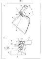
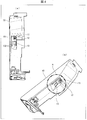
図2は、前面パネル20が閉じた状態となる位置にあるときの蓋開閉機構30の動作を説明するための図であり、(a)は、本体10の断面を示す図であり、(b)は、(a)の要部を拡大した拡大図である。
図2は、前面パネル20が閉じた状態となる位置にあるときの蓋開閉機構30の動作を説明するための図であり、(a)は、本体10の断面を示す図であり、(b)は、(a)の要部を拡大した拡大図である。
図3は、前面パネル20がダストボックス40を着脱可能な状態となる位置まで開いた状態のときの蓋開閉機構30の動作を説明するための図であり、(a)は、本体10の断面を示す図であり、(b)は、(a)の要部を拡大した拡大図である。
図4は、前面パネル20が当該前面パネル20を着脱可能な状態となる位置まで開いた状態のときの蓋開閉機構30の動作を説明するための図であり、(a)は、本体10の断面を示す図であり、(b)は、(a)の要部を拡大した拡大図である。
蓋開閉機構30によって、前面パネル20は、回転軸32(後述)を中心として、矢印X・Y方向に回転可能に支持されている。つまり、前面パネル20は、図2の(a)に示す閉状態となる位置(閉塞位置)から、矢印X方向に回転して、少し開いて、図3の(a)に示すダストボックス40を着脱可能な状態となる位置(固定支持位置)で一時的に固定支持され、さらに矢印X方向に回転して、さらに開いて、図4の(a)に示す当該前面パネル20を着脱可能な状態となる位置(離脱可能位置)に回転する。また、前面パネル20は、図4の(a)に示す状態から、矢印Y方向に回転して、図3の(a)に示す状態を経て、図2の(a)に示す閉状態となる。ここで、閉状態とは、前面パネル20によって室内機1の本体10の前面を閉じた状態をいう。通常、前面パネル20の閉状態のときにエアコンの冷房、暖房等の空調が実行される。また、ダストボックス40を着脱可能な状態とは、本体10に設置されているダストボックス40やフィルタを当該本体10に対して着脱可能な状態まで前面パネル20が開いた状態をいう。さらに、前面パネル20を着脱可能な状態とは、ダストボックス40を着脱可能な状態よりもさらに前面パネル20が開いた状態であり、当該前面パネル20を本体10に対して着脱可能な状態をいう。
蓋開閉機構30は、上述のように、前面パネル20を本体10に対して回動可能に支持するための機構であって、前面パネル20を支持するアーム(支持部材)31と、アーム31に設けられ、本体10に形成された軸受部(軸受上部)11・軸受部(軸受下部)12に回動自在に支持され、所定の角度回転したとき当該軸受部11・12から離脱可能な状態となる円筒状の回転軸32と、アーム31に設けられ、回転軸32が上記所定の角度回転する間で、本体10に形成されたストッパ受部13に係合され、回転中の上記前面パネル20を所定の角度で固定支持するストッパ(固定支持軸)33と、を備える。
軸受部(軸受上部)11・軸受部(軸受下部)12は、互いに対向配置され、回転軸32を上下から挟み込むにして回動可能に支持している。軸受部11・12は、何れも弾性を有する部材、例えば樹脂で形成されている。なお、本実施形態では、軸受部12を撓む構造とし、軸受部11は撓まない構造(少なくとも回転軸32の着脱時においては撓まない強度を有する)としている。なお、軸受部11が撓む構造とし、軸受部12を撓まない構造としてもよい。ここで、軸受部11は、円筒状の回転軸の外周面32を受ける円弧状の軸上側支持面を有している。軸上側支持面は、前面パネル20が閉じた状態(図2(b)参照)に回転軸32が位置する際に、回転軸32の真上から回転軸32の中心よりも前方側かつ上方(ただし、回転軸32の真上に接する接線よりも下方)にかけて位置している。ここで、前方とは、本体10から前面パネル20が取り外される方向をいう。また、上方とは、本体10において、鉛直方向(重力の方向)と反対側の方向をいう。また、軸受部12は、円筒状の回転軸の外周面32を受ける円弧状の軸下側支持面を有している。軸下側支持面は、前面パネル20が閉じた状態(図2(b)参照)に回転軸32が位置する際に、回転軸32の真下から回転軸32の中心よりも前方側かつ下方(ただし、回転軸32の真下に接する接線よりも上方)にかけて位置している。これにより、回転軸32は、離脱するまで、軸受部11の軸上側支持面と軸受部12の軸下側支持面に密着した状態となる。また、軸受部11・12は、それぞれ回転軸32を支持する面に、当該回転軸32が前面パネル20の取出し方向(本体10から前面パネル20を取り出す方向)への移動を規制するための突起部(第1突起部)11a,突起部(第2突起部)12aが形成されている。突起部11aは、軸上側支持面の前側端部から前方側へ連続する円弧状の凸部である。また、突起部12aは、軸下側支持面の前側端部から水平方向に延びる面を有し、その面の前方端部から前方下方へ伸びる面からなる。突起部11a,12aによって、図2の(b)に示す閉状態、図3の(b)に示すダストボックス40を着脱可能な状態、図4の(b)に示す前面パネル20を着脱可能な状態の何れにおいても、回転軸32の移動が規制される。但し、図4の(b)に示す前面パネル取り外し状態では、前面パネル20を矢印Z方向に移動させることで、回転軸32の移動により、軸受部11は撓まず、軸受部12が撓んで、突起部11a,12aを当該回転軸32が乗り越えるようになっている。突起部11a・12aよりも左側の軸受部11・12の上下方向の幅よりも、突起部11a、12aの右側のガイド空間の幅は広くなっている。これにより、前面パネルを取り付ける際に、ガイド空間に軸を入れやすくなり、軸受部11・12はしっかりと軸を支持することができる。また、ガイド空間は、軸受部11・12よりも下方に位置している。これにより、前面パネル20を取り付ける際に、軸受部12に回転軸が接触しやすくなることで、軸受部12を撓ませやすくなり、取り付けやすくなる。また、突起部11aの頂点から軸中心xを通る線までの距離(高さ)D1と突起部12aの頂点からの軸中心xを通る線間までの距離(高さ)D2は、距離D2の方が大きい(図6参照)。このようにすることで、前面パネル20を取り外す際に、回転軸32が軸受部12側へ誘導されやすくなる。
本実施形態では、回転軸32は、図2の(b)に示すように、円筒状であり外周面32aの一部が平らになっている。この平らな面を、Dカット面32a1と称する。外周面32aの残りの面を周面32a2とする。回転軸32は、回転して、Dカット面32a1が、図4の(b)に示すように、前面パネル20の取り外し状態のときに、軸受部12に対向する位置に来るように形成されている。これにより、回転軸32は、Dカット面32a1により軸受部12の突起部12aを乗り越えやすくなる。ここでは、軸受11にバネ性を持たせず(少なくとも回転軸32の着脱時においては撓まない強度を有する)、軸受部12にバネ性を持たせることで、回転軸32のDカット面32a1が当該軸受部12を下側に押し下げるようにして、当該回転軸32が軸受部11・12から取外しできるようになる。
しかも、回転軸32は、外周面32aのうちDカット面32a1以外の周面32a2が常に軸受部11に密着するようになっているので、当該回転軸32が軸受部11・12から容易に抜けないようになっている。特に、図4の(a)(b)に示す前面パネル20の取外し状態以外においては、回転軸32は軸受部11・12の両方に外周面32aが密着するようになっているため、当該回転軸32が軸受部11・12からさらに抜けにくくなっている。
ストッパ33は、回転軸32と同様に、断面略円状の部材からなり、外周面33aがストッパ受部13の凹状の係合面に密着可能となっている。つまり、図3の(a)(b)に示すように、ダストボックス取外し状態のとき、ストッパ33は、ストッパ受部13の係合面に密着するようになっている。これにより、回転軸32の回転、すなわち前面パネル20の回転を規制すると共に、所定の位置で当該前面パネル20の開放状態を保持する保持力を強めることができる。
ストッパ受部13は、図3の(b)に示すように、ダストボックス40を着脱可能な状態において、アーム31に形成されたストッパ33を係合するものである。なお、ストッパ受部13は、図2の(b)に示す閉状態、図4の(b)に示す前面パネル20を着脱可能な状態のときには、ストッパ33との係合が解除された状態となる。
(蓋開閉機構30の動作)
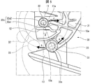
図5は、図3の(b)に示すダストボックス40を着脱可能な状態の蓋開閉機構30の動作を説明するための図である。
図5は、図3の(b)に示すダストボックス40を着脱可能な状態の蓋開閉機構30の動作を説明するための図である。
ストッパ33がストッパ受部13によって係合される係合位置は、回転軸32から鉛直方向(重力の方向)に伸びる直線(軸線)から、前面パネル20の取り外し方向(前方)にずれている。この場合、係合位置は、回転軸32から鉛直方向に伸びる直線と、回転軸32からストッパ33に向かう直線とが角度θ分離れた位置となる。角度θは、15°が好ましいが、これに限定されるものではなく、0°よりも大きければよい。つまり、係合位置は、回転軸32から鉛直方向に伸びる直線から少しでも前方(前面パネル20の取り外し方向)にあればよい。また、ストッパ33が係合位置にあるとき、回転軸32は、外周面32aが軸受部11に密着している。
このように、係合位置は、回転軸32から鉛直方向に伸びる直線よりも前方にあるので、前面パネル20を取りはず際は、回転軸32を支点としてストッパ33が矢印A方向に回転するため、ストッパ33の外周面33aとストッパ受部13の接触面13aとの係合は容易に解除される。一方、ストッパ33が係合位置にあるとき、回転軸32は、外周面32aが軸受部11に密着しているので、前面パネル20を閉状態にする際は、回転軸32を支点としてストッパ33が矢印B方向に回転する。この場合、ストッパ33とストッパ受部13との係合力が増し、支点である回転軸32が矢印C方向に移動しようとするが、回転軸32が軸受部11によってしっかりと保持されているため、支点が回転軸32から移動しない。このため、前面パネル20をスムーズに閉じることができる。しかも、前面パネル20を閉じる場合に生じる、各部の摩擦による異音の発生も抑えることができる。さらに、上記の角度θを変えることにより、ストッパ33とストッパ受部13との係合力を自由に設定できる。
また、図2の(a)(b)に示す前面パネル20の閉状態のとき、回転軸32は、軸受部11・12に対して面で密着した状態で挟み込まれているため、前面パネル20を確実に固定することができる。また、前面パネル20を図4の(a)(b)から前面パネル20をさらに無理矢理開いたとしても、図4の(a)(b)に示す状態以上に矢印X方向に回転すれば前面パネル20が容易に取り外せる構成となっているため、前面パネル20の開閉機構を故障させることはない。
(蓋開閉機構30による係合力調整)
図6は、Cを説明するための図である。
図6は、Cを説明するための図である。
図7は、前面パネル20の保持強度の調整を説明するための図である。
図8は、軸受部12のスリット位置高さの調整、上記ストッパ13のスリット位置高さの調整を説明するための図である。
図9は、図8の要部Hの拡大図である。
図4の(a)(b)に示す前面パネル20の取り外し状態において、図6に示すように、回転軸32の軸中心Xから当該回転軸32の外周面32aのDカット面32a1までの距離D2および軸受部12におけるスリット(図示せず)位置高さEを調整することで、前面パネル20の取り外し強度(取り外しの固さ)の調整を容易に行うことができる。
また、図3の(a)(b)に示すダストボックス取り外し状態において、図7に示すように、ストッパ受部13の接触面13aの底面から頂部13bまでの距離Gおよびストッパ受部13のスリット(図示せず)位置高さFを調整することで、ストッパ33の係合力と、係合固さの調整を容易に行うことができる。
例えば、図8および図9に示すように、軸受部12に設けられたスリット101の高さE、ストッパ受部13に設けられたスリット102の高さFを調整する。E、Fを高くすれば、軸受部12、ストッパ受部13が撓みやすくなるので、前面パネル20の取り外し強度が弱まる。逆に、E、Fを低くすれば、軸受部12、ストッパ受部13が撓みにくくなるので、前面パネル20の取り外し強度が強まる。
また、前面パネル20の取り外し強度を調整するには、図10に示すように、ストッパ受部13の裏面にリブ103・103を設け、このリブ103・103の高さを調整するようにしてもよい。この場合、リブ103・103の高さは、高ければ、それだけストッパ受部13が撓みにくくなるため、前面パネル20の取り外し強度が強まる。
以上のことから、前面パネル20の取付け、取外し時の固さの調整が容易になり、また、前面パネル20の一時固定時(ダストボックス取外し時)の保持力の調整が容易になり、前面パネル20の取付け、取外し時の異音を軽減できるという効果を奏する。
また、回転軸32の形状、ストッパ33の形状を変更することで、様々な効果を奏する蓋開閉機構を実現することができる。この点について、下記の実施形態2~5で説明する。
〔実施形態2〕
本発明の他の実施形態について説明すれば、以下のとおりである。なお、説明の便宜上、前記実施形態にて説明した部材と同じ機能を有する部材については、同じ符号を付記し、その説明を省略する。
本発明の他の実施形態について説明すれば、以下のとおりである。なお、説明の便宜上、前記実施形態にて説明した部材と同じ機能を有する部材については、同じ符号を付記し、その説明を省略する。
図11は、本実施形態に係る蓋開閉機構130におけるダストボックス取外し状態の動作を説明するための図である。
蓋開閉機構130は、前記実施形態1の蓋開閉機構30とほぼ同じ構成であり、異なるのは、回転軸132の断面形状である。回転軸132の断面形状は、図11に示すように、Dカット面のない円形状である。つまり、回転軸132は、上記のように、断面略円形状であり、上記軸受部11・12の回転軸132の軸受け面(軸上側支持面、軸下側支持面)に、上記回転軸132の外周面(回転面)が密着できる形状に形成されている。なお、ストッパ133は、前記実施形態の蓋開閉機構30のストッパ33と同じ形状であり、断面形状が円形状である。
回転軸132では、Dカット面が廃止されているので、当該回転軸132の外周面は常に軸受部11・12に密着した状態となるので、前面パネル20の取外し状態であっても、回転軸132にDカット面がない分、回転軸132と軸受部12との密着力が増し、前面パネル20の抜き強度をアップさせることができる。つまり、前面パネル20が本体10から容易に脱落しないようにできる。
〔実施形態3〕
本発明の他の実施形態について説明すれば、以下のとおりである。なお、説明の便宜上、前記実施形態にて説明した部材と同じ機能を有する部材については、同じ符号を付記し、その説明を省略する。
本発明の他の実施形態について説明すれば、以下のとおりである。なお、説明の便宜上、前記実施形態にて説明した部材と同じ機能を有する部材については、同じ符号を付記し、その説明を省略する。
図12は、本実施形態に係る蓋開閉機構230におけるダストボックス取外し状態の動作を説明するための図である。
蓋開閉機構230は、前記実施形態1の蓋開閉機構30とほぼ同じ構成であり、異なるのは、ストッパ233の形状である。ストッパ233の断面形状は、図12に示すように、Dカット面を有する形状である。なお、回転軸232は、前記実施形態1の蓋開閉機構30の回転軸32と同じ、断面形状がDカット面を有する円形状である。
また、本実施形態では、ストッパ受部213のストッパ233との当接面を平面形状としている。これにより、前面パネル20のダストボックス取外し状態のとき、ストッパ233のDカット面とストッパ受部213の当接面とが対向して密着可能にすることができる。
これにより、前面パネル20のダストボックス取外し状態での当該前面パネル20を安定して開放させることが可能となる。つまり、ストッパ233のDカット面とストッパ受部213の当接面とが密着したときの密着面の傾きを調整することで、前面パネル20の開閉角度を一定に保つことができる。
また、前記実施形態1の図6で説明したように、回転軸232の軸中心XからDカット面までの距離および軸受部12およびストッパ受部13におけるスリット位置高さを調整することで、前面パネル20の取り外し強度(取り外しの固さ)の調整を容易に行うことができる。
〔実施形態4〕
本発明の他の実施形態について説明すれば、以下のとおりである。なお、説明の便宜上、前記実施形態にて説明した部材と同じ機能を有する部材については、同じ符号を付記し、その説明を省略する。
本発明の他の実施形態について説明すれば、以下のとおりである。なお、説明の便宜上、前記実施形態にて説明した部材と同じ機能を有する部材については、同じ符号を付記し、その説明を省略する。
図13は、本実施形態に係る蓋開閉機構330におけるダストボックス取外し状態の動作を説明するための図である。
蓋開閉機構330は、前記実施形態1の蓋開閉機構30とほぼ同じ構成であり、異なるのは、回転軸332とストッパ333の形状である。回転軸332は、図13に示すように、Dカット面のない円形状である。ストッパ333は、前記実施形態3のストッパ233と同様に、Dカット面を有する形状である。
また、本実施形態では、前記実施形態3と同様に、ストッパ受部213のストッパ233との当接面を平面形状としている。具体的には、ストッパ233は、上記ストッパ受部213によって支持されている外周面に、当該ストッパ233が上記ストッパ受部213から離脱する方向と平行になる平面が、上記前面パネル20の離脱可能位置において、上記ストッパ受部213の上面に対向している。
これにより、ストッパ233とストッパ受部213とを面で密着させることが可能となる。これにより、密着面の傾きを調整することで、固定支持位置での前面パネル20の開閉角度が調整できる。
これにより、ストッパ233のDカット面とストッパ受部213の当接面とが密着したときの密着面の傾きを調整することで、前面パネル20の開閉角度を一定に保つことができる。
しかも、回転軸332では、Dカット面が廃止されているので、当該回転軸332の外周面は常に軸受部11・12に密着した状態が継続する。このため、前面パネル20の取外し状態であっても、回転軸332にDカット面がない分、回転軸332と軸受部12との密着力が増し、前面パネル20の抜き強度をアップさせることができる。
〔実施形態5〕
本発明の他の実施形態について説明すれば、以下のとおりである。なお、説明の便宜上、前記実施形態にて説明した部材と同じ機能を有する部材については、同じ符号を付記し、その説明を省略する。
本発明の他の実施形態について説明すれば、以下のとおりである。なお、説明の便宜上、前記実施形態にて説明した部材と同じ機能を有する部材については、同じ符号を付記し、その説明を省略する。
蓋開閉機構430は、前記実施形態1の蓋開閉機構30とほぼ同じ構成であり、異なるのは、ストッパ433の形状である。ストッパ433は、図14に示すように、ストッパ受部213に対向する部分にリブ433aが形成されている。なお、回転軸432は、前記実施形態の蓋開閉機構30の回転軸32と同じ形状である。
また、本実施形態では、ストッパ受部213のストッパ433との当接面を平面形状としている。これにより、前面パネル20のダストボックス取外し状態のとき、ストッパ433のリブ433aとストッパ受部213の当接面とが対向して接触した状態となる。
これにより、リブ433aの突出した長さを調整することで、前面パネル20のダストボックス取外し状態で当該前面パネル20の保持力の微調整を容易にし、また、前面パネル20の開閉角度の微調整を容易にできる。
〔まとめ〕
本発明の態様1に係る蓋開閉機構は、筐体(本体10)に着脱可能に取り付けられた蓋(前面パネル20)の開閉を行う蓋開閉機構であって、上記蓋(前面パネル20)を支える支持部材(アーム31)と、上記支持部材(アーム31)に設けられ、上記筐体(本体10)に形成された軸受部11・12に回動自在に支持され、所定の角度回転したとき当該軸受部11・12から離脱可能な状態となる回転軸32と、上記支持部材(アーム31)に設けられ、上記回転軸32が上記所定の角度回転する間で、回転中の上記蓋(前面パネル20)を別の所定の角度で固定支持する固定支持軸(ストッパ33)と、を備え、上記回転軸32は、上記蓋(前面パネル20)の閉塞位置(前面パネルの閉状態となる位置)から上記固定支持軸(ストッパ33)による固定支持位置(ダストボックス40を着脱可能な状態となる位置)を越えて当該蓋(前面パネル20)の離脱可能位置(前面パネル20の着脱可能な状態となる位置)までの間、上記軸受部11・12の軸受け面に当該回転軸32の回転面が接触しながら回転することを特徴としている。
本発明の態様1に係る蓋開閉機構は、筐体(本体10)に着脱可能に取り付けられた蓋(前面パネル20)の開閉を行う蓋開閉機構であって、上記蓋(前面パネル20)を支える支持部材(アーム31)と、上記支持部材(アーム31)に設けられ、上記筐体(本体10)に形成された軸受部11・12に回動自在に支持され、所定の角度回転したとき当該軸受部11・12から離脱可能な状態となる回転軸32と、上記支持部材(アーム31)に設けられ、上記回転軸32が上記所定の角度回転する間で、回転中の上記蓋(前面パネル20)を別の所定の角度で固定支持する固定支持軸(ストッパ33)と、を備え、上記回転軸32は、上記蓋(前面パネル20)の閉塞位置(前面パネルの閉状態となる位置)から上記固定支持軸(ストッパ33)による固定支持位置(ダストボックス40を着脱可能な状態となる位置)を越えて当該蓋(前面パネル20)の離脱可能位置(前面パネル20の着脱可能な状態となる位置)までの間、上記軸受部11・12の軸受け面に当該回転軸32の回転面が接触しながら回転することを特徴としている。
上記構成によれば、蓋の回転軸が、当該蓋の閉塞位置から固定支持軸による支持位置を越えて当該蓋の離脱可能位置までの間、筐体に設けられた軸受部に面で密着状態であることで、蓋の回転中心(支点)は常に回転軸であり、支点が回転軸から移動することがないため、蓋の開閉が円滑になる。
これにより、蓋の筐体への取り付け、取り外しおよび開閉が円滑に行え、且つ、蓋の筐体への取り付け、取り外しおよび開閉に伴う異音の発生を抑制できる。
本発明の態様2に係る蓋開閉機構は、上記態様1において、上記固定支持位置における上記固定支持軸(ストッパ33)の位置は、上記回転軸32から鉛直方向に伸びる軸線に対して、上記蓋(前面パネル20)の離脱可能位置側にずれていてもよい。
上記構成によれば、上記固定支持位置における上記固定支持軸の位置は、上記回転軸から鉛直方向に伸びる軸線に対して、上記蓋の離脱可能位置側にずれていることで、固定支持位置から蓋の離脱可能位置まで固定支持軸が容易に移動できる。一方、固定支持位置から、蓋の閉塞位置までは、回転軸から鉛直方向に伸びる軸線を越える必要があるため、蓋の回転に少し負荷がかかり、回転軸が蓋の回転方向と反対方向に移動しようとするが、回転軸は軸受部に面で密着状態であるため、回転軸は蓋の回転方向と反対方向に移動することはない。よって、蓋を安定して開閉することができる。
本発明の態様3に係る蓋開閉機構は、上記態様1または2において、上記回転軸32は、上記軸受部
11・12によって支持されている外周面32aに、当該回転軸32が上記軸受部11・12から離脱する方向と平行になる平面が形成され、上記回転軸32に形成された平面は、上記蓋(前面パネル20)の離脱可能位置において、上記軸受部11・12による外周面32aの密着方向と反対側に位置してもよい。
11・12によって支持されている外周面32aに、当該回転軸32が上記軸受部11・12から離脱する方向と平行になる平面が形成され、上記回転軸32に形成された平面は、上記蓋(前面パネル20)の離脱可能位置において、上記軸受部11・12による外周面32aの密着方向と反対側に位置してもよい。
上記構成によれば、回転軸に形成された平面は、上記蓋の離脱可能位置において、上記軸受部による外周面の密着方向と反対側に位置することで、蓋の離脱可能位置から蓋を離脱させるときに、回転軸を軸受部から円滑に取り外すことが可能となる。これにより、蓋を離脱可能位置まで開放させれば、当該蓋を筐体から容易に取り外すことができる。
本発明の態様4に係る蓋開閉機構は、上記態様1~3の何れか1態様において、上記回転軸132は、断面略円形状であり、上記軸受部11・12の回転軸受け面は、上記回転軸132の外周面が密着できる形状に形成されていてもよい。
上記構成によれば、回転軸は、断面略円形状であり、上記軸受部の回転軸受け面は、上記回転軸の外周面が密着できる形状に形成されていることで、回転軸の外周面は常に軸受部に密着した状態となるので、蓋の取外し状態であっても、回転軸にDカット面がない分、回転軸と軸受部との密着力が増し、蓋の抜き強度をアップさせることができる。つまり、蓋が筐体から容易に脱落しないようにできる。
本発明の態様5に係る蓋開閉機構は、上記態様1~4の何れか1態様において、上記固定支持軸(ストッパ233)は、上記固定支持位置において、上記筐体(本体10)に形成された固定支持軸受部(ストッパ受部213)に支持され、上記固定支持軸(ストッパ233)の、上記固定支持軸受部(ストッパ受部213)によって支持されている外周面に、当該固定支持軸(ストッパ233)が上記固定支持軸受部(ストッパ受部213)から離脱する方向と平行になる平面が形成され、上記固定支持軸(ストッパ233)に形成された平面は、上記蓋(前面パネル20)の離脱可能位置において、上記固定支持軸受部(ストッパ受部213)の上面に対向していてもよい。
上記構成によれば、固定支持軸は、上記固定支持軸受部によって支持されている外周面に、当該固定支持軸が上記固定支持軸受部から離脱する方向と平行になる平面が、上記蓋の離脱可能位置において、上記固定支持軸受部の上面に対向していることで、固定支持軸と固定支持軸受部とを面で密着させることが可能となる。これにより、密着面の傾きを調整することで、固定支持位置での蓋の開閉角度が調整できる。
本発明の態様6に係る蓋開閉機構は、上記態様1~4の何れか1態様において、上記固定支持軸(ストッパ333)は、上記固定支持位置において、上記筐体(本体10)に形成された固定支持軸受部(ストッパ受部213)に支持され、上記固定支持軸(ストッパ333)の、上記固定支持軸受部(ストッパ受部213)によって支持されている外周面に、当該固定支持軸受部(ストッパ受部213)に向かって突出しているリブ433aが少なくとも1個設けられていてもよい。
上記構成によれば、上記固定支持軸は、上記固定支持軸受部によって支持されている外周面に、当該固定支持軸受部に向かって突出しているリブが少なくとも1個設けられていることで、固定支持軸と固定支持受部との間の距離をリブの長さによって調整することができる。つまり、リブの長さを調整することで、固定支持軸と固定支持受部との密着度、密着部分の角度を調整することが可能となる。これにより、蓋の離脱可能状態で当該蓋の保持力の微調整を容易にし、また、蓋の開閉角度の微調整を容易にできる。
本発明の態様7に係る蓋開閉機構は、上記態様1~6の何れか1態様において、上記軸受部11・12は、上記回転軸32を上側から支持する軸受上部(軸受部11)と、当該回転軸32を下側から支持する軸受下部(軸受部12)とを含み、上記回転軸32が離脱する際に、上記軸受上部(軸受部11)および上記軸受下部(軸受部12)の何れか一方が撓むことが好ましい。
上記の構成によれば、回転軸の支持を適切に行いつつ、回転軸の離脱を容易に行える。
本発明の態様8に係る蓋開閉機構は、上記態様7において、上記軸受上部(軸受部11)の上記回転軸32を支持する面に、当該回転軸32が離脱する方向への移動を規制するための第1突起部(突起部11a)が形成され、上記軸受下部(軸受部12)の上記回転軸32を支持する面に、当該回転軸32が離脱する方向への移動を規制するための第2突起部(突起部12a)が形成され、上記第1突起部(突起部11a)の頂点から上記回転軸32の軸中心xを通る線までの距離(高さ)D1よりも上記第2突起部(突起部11a)の頂点から上記回転軸32の軸中心xを通る線までの距離(高さ)D2の方が大きいことが好ましい。
上記の構成によれば、蓋を取り外す際に、回転軸が軸受下部側へ誘導されやすくなるため、蓋を容易に取り筈ことが可能となる。
本発明の態様9に係る蓋開閉機構は、上記態様1~8の何れか1態様において、上記回転軸32が離脱する方向にガイドするガイド空間は、上記軸受部11・12よりも下方に位置していることが好ましい。
上記の構成によれば、蓋を取り付ける際に、ガイド空間に軸を入れやすくなり、軸受部はしっかりと軸を支持することができる。
本発明の態様10に係る空気調和機は、上記態様1~9の何れか1態様に係る蓋開閉機構を備えていることを特徴とする。
なお、本発明の蓋開閉機構は、空気調和機として、エアコンの室内機に好適であるが、これに限定されるものではなく、空気清浄機に適用してもよい。また、蓋を開閉し、且つ、蓋を取り外す必要のある機器で有れば、どのような機器に対しても適用可能である。
また、本実施の形態ではフィルタ清掃装置を備えたエアコンの室内機を用いて説明したが、フィルタ清掃装置を有しないエアコンの室内機にも適用できる。その際、前面パネルを開くことで、フィルタの着脱を行うことができる。言い換えれば、フィルタ清掃装置を有しないエアコン室内機においては、図3をフィルタ着脱状態と読み替えればよい。もちろん、ダストボックスやフィルタ以外に着脱可能な部品(例えば、静電集塵装置などの機器やイオン発生ユニット)を有するものであれば、図3を部品着脱状態と読み替えればよい。ダストボックス、フィルタや、着脱可能な部品を着脱できる状態を、部品着脱状態と称してもよい。
本発明は上述した各実施形態に限定されるものではなく、請求項に示した範囲で種々の変更が可能であり、異なる実施形態にそれぞれ開示された技術的手段を適宜組み合わせて得られる実施形態についても本発明の技術的範囲に含まれる。さらに、各実施形態にそれぞれ開示された技術的手段を組み合わせることにより、新しい技術的特徴を形成することができる。
1 室内機
10 本体(筐体)
10a 前面
11 軸受部(軸受上部)
11a 突起部
12 軸受部(軸受下部)
12a 突起部
13 ストッパ受部(固定支持軸受部)
13a 接触面
13b 頂部
20 前面パネル(蓋)
30 蓋開閉機構
31 アーム
32 回転軸
32a 外周面
33 ストッパ(固定支持軸)
33a 外周面
40 ダストボックス
130 蓋開閉機構
132 回転軸
133 ストッパ(固定支持軸)
213 ストッパ受部(固定支持軸受部)
230 蓋開閉機構
232 回転軸
233 ストッパ(固定支持軸)
330 蓋開閉機構
332 回転軸
333 ストッパ(固定支持軸)
430 蓋開閉機構
432 回転軸
433 ストッパ(固定支持軸)
433a リブ
10 本体(筐体)
10a 前面
11 軸受部(軸受上部)
11a 突起部
12 軸受部(軸受下部)
12a 突起部
13 ストッパ受部(固定支持軸受部)
13a 接触面
13b 頂部
20 前面パネル(蓋)
30 蓋開閉機構
31 アーム
32 回転軸
32a 外周面
33 ストッパ(固定支持軸)
33a 外周面
40 ダストボックス
130 蓋開閉機構
132 回転軸
133 ストッパ(固定支持軸)
213 ストッパ受部(固定支持軸受部)
230 蓋開閉機構
232 回転軸
233 ストッパ(固定支持軸)
330 蓋開閉機構
332 回転軸
333 ストッパ(固定支持軸)
430 蓋開閉機構
432 回転軸
433 ストッパ(固定支持軸)
433a リブ
Claims (7)
- 筐体に着脱可能に取り付けられた蓋の開閉を行う蓋開閉機構であって、
上記蓋を支える支持部材と、
上記支持部材に設けられ、上記筐体に形成された軸受部に回動自在に支持され、所定の角度回転したとき当該軸受部から離脱可能な状態となる回転軸と、
上記支持部材に設けられ、上記回転軸が上記所定の角度回転する間で、回転中の上記蓋を別の所定の角度で固定支持する固定支持軸と、を備え、
上記回転軸は、上記蓋の閉塞位置から上記固定支持軸による固定支持位置を越えて当該蓋の離脱可能位置までの間、上記軸受部の軸受け面に当該回転軸の回転面が接触しながら回転することを特徴とする蓋開閉機構。 - 上記固定支持位置における上記固定支持軸の位置は、上記回転軸から鉛直方向に伸びる軸線に対して、上記蓋の離脱可能位置側にずれていることを特徴とする請求項1に記載の蓋開閉機構。
- 上記回転軸は、上記軸受部によって支持されている外周面に、当該回転軸が上記軸受部から離脱する方向と平行になる平面が形成され、
上記回転軸に形成された平面は、上記蓋の離脱可能位置において、上記軸受部による外周面の密着方向と反対側に位置することを特徴とする請求項1または2に記載の蓋開閉機構。 - 上記軸受部は、上記回転軸を上側から支持する軸受上部と、当該回転軸を下側から支持する軸受下部とを含み、
上記回転軸が離脱する際に、上記軸受上部および上記軸受下部の何れか一方が撓むことを特徴とする請求項1~3の何れか1項に記載の蓋開閉機構。 - 上記軸受上部の上記回転軸を支持する面に、当該回転軸が離脱する方向への移動を規制するための第1突起部が形成され、
上記軸受下部の上記回転軸を支持する面に、当該回転軸が離脱する方向への移動を規制するための第2突起部が形成され、
上記第1突起部の頂点から上記回転軸の軸中心を通る線までの距離よりも上記第2突起部の頂点から上記回転軸の軸中心を通る線までの距離の方が大きいことを特徴とする請求項4に記載の蓋開閉機構。 - 上記回転軸を離脱する方向にガイドするガイド空間は、上記軸受部よりも下方に位置していることを特徴とする請求項1~5の何れか1項に記載の蓋開閉機構。
- 請求項1~6の何れか1項に記載の蓋開閉機構を備えた空気調和機。
Priority Applications (2)
| Application Number | Priority Date | Filing Date | Title |
|---|---|---|---|
| JP2019501016A JP7088903B2 (ja) | 2017-02-27 | 2017-07-11 | 蓋開閉機構、空気調和機 |
| CN201780053460.2A CN110312901B (zh) | 2017-02-27 | 2017-07-11 | 盖开闭机构、空气调节机 |
Applications Claiming Priority (2)
| Application Number | Priority Date | Filing Date | Title |
|---|---|---|---|
| JP2017-035078 | 2017-02-27 | ||
| JP2017035078 | 2017-02-27 |
Publications (1)
| Publication Number | Publication Date |
|---|---|
| WO2018154807A1 true WO2018154807A1 (ja) | 2018-08-30 |
Family
ID=63252544
Family Applications (1)
| Application Number | Title | Priority Date | Filing Date |
|---|---|---|---|
| PCT/JP2017/025221 Ceased WO2018154807A1 (ja) | 2017-02-27 | 2017-07-11 | 蓋開閉機構、空気調和機 |
Country Status (3)
| Country | Link |
|---|---|
| JP (1) | JP7088903B2 (ja) |
| CN (1) | CN110312901B (ja) |
| WO (1) | WO2018154807A1 (ja) |
Citations (12)
| Publication number | Priority date | Publication date | Assignee | Title |
|---|---|---|---|---|
| JPH05272777A (ja) * | 1992-03-26 | 1993-10-19 | Hitachi Ltd | 空気調和機 |
| JPH0894118A (ja) * | 1994-09-29 | 1996-04-12 | Toshiba Corp | 室内ユニット |
| JPH08159508A (ja) * | 1994-12-09 | 1996-06-21 | Sanyo Electric Co Ltd | 空気調和機 |
| JPH0914688A (ja) * | 1995-06-23 | 1997-01-17 | Toshiba Corp | 空気調和機 |
| JPH09137961A (ja) * | 1995-11-16 | 1997-05-27 | Daikin Ind Ltd | パネルの取付構造 |
| JPH10232026A (ja) * | 1997-02-20 | 1998-09-02 | Fujitsu General Ltd | 空気調和機のグリル固定装置 |
| JP2000130796A (ja) * | 1998-10-30 | 2000-05-12 | Mitsubishi Electric Corp | 空気調和機の室内ユニット |
| JP2001082758A (ja) * | 1999-09-14 | 2001-03-30 | Mitsubishi Electric Corp | 空気調和機の室内ユニット |
| JP2003148762A (ja) * | 2001-11-12 | 2003-05-21 | Matsushita Electric Ind Co Ltd | 空気調和機 |
| JP2004084974A (ja) * | 2002-08-23 | 2004-03-18 | Fujitsu General Ltd | 空気調和機 |
| JP2008051434A (ja) * | 2006-08-25 | 2008-03-06 | Daikin Ind Ltd | 空気調和機 |
| JP2013217504A (ja) * | 2012-04-04 | 2013-10-24 | Mitsubishi Electric Corp | 空気調和機の室内機 |
Family Cites Families (4)
| Publication number | Priority date | Publication date | Assignee | Title |
|---|---|---|---|---|
| CN2816641Y (zh) * | 2005-04-25 | 2006-09-13 | 海尔集团公司 | 空调室内机上进风栅的支撑结构 |
| JP2009097762A (ja) * | 2007-10-16 | 2009-05-07 | Hitachi Appliances Inc | 空気調和機 |
| JP2009180486A (ja) * | 2008-02-01 | 2009-08-13 | Corona Corp | 空気調和機 |
| CN201331162Y (zh) * | 2008-12-17 | 2009-10-21 | 珠海格力电器股份有限公司 | 一种用于空调面板的支撑装置 |
-
2017
- 2017-07-11 JP JP2019501016A patent/JP7088903B2/ja active Active
- 2017-07-11 CN CN201780053460.2A patent/CN110312901B/zh active Active
- 2017-07-11 WO PCT/JP2017/025221 patent/WO2018154807A1/ja not_active Ceased
Patent Citations (12)
| Publication number | Priority date | Publication date | Assignee | Title |
|---|---|---|---|---|
| JPH05272777A (ja) * | 1992-03-26 | 1993-10-19 | Hitachi Ltd | 空気調和機 |
| JPH0894118A (ja) * | 1994-09-29 | 1996-04-12 | Toshiba Corp | 室内ユニット |
| JPH08159508A (ja) * | 1994-12-09 | 1996-06-21 | Sanyo Electric Co Ltd | 空気調和機 |
| JPH0914688A (ja) * | 1995-06-23 | 1997-01-17 | Toshiba Corp | 空気調和機 |
| JPH09137961A (ja) * | 1995-11-16 | 1997-05-27 | Daikin Ind Ltd | パネルの取付構造 |
| JPH10232026A (ja) * | 1997-02-20 | 1998-09-02 | Fujitsu General Ltd | 空気調和機のグリル固定装置 |
| JP2000130796A (ja) * | 1998-10-30 | 2000-05-12 | Mitsubishi Electric Corp | 空気調和機の室内ユニット |
| JP2001082758A (ja) * | 1999-09-14 | 2001-03-30 | Mitsubishi Electric Corp | 空気調和機の室内ユニット |
| JP2003148762A (ja) * | 2001-11-12 | 2003-05-21 | Matsushita Electric Ind Co Ltd | 空気調和機 |
| JP2004084974A (ja) * | 2002-08-23 | 2004-03-18 | Fujitsu General Ltd | 空気調和機 |
| JP2008051434A (ja) * | 2006-08-25 | 2008-03-06 | Daikin Ind Ltd | 空気調和機 |
| JP2013217504A (ja) * | 2012-04-04 | 2013-10-24 | Mitsubishi Electric Corp | 空気調和機の室内機 |
Also Published As
| Publication number | Publication date |
|---|---|
| CN110312901A (zh) | 2019-10-08 |
| JP7088903B2 (ja) | 2022-06-21 |
| JPWO2018154807A1 (ja) | 2019-12-19 |
| CN110312901B (zh) | 2022-03-11 |
Similar Documents
| Publication | Publication Date | Title |
|---|---|---|
| US10203124B2 (en) | Indoor device for air conditioner having wind visors | |
| US9297542B2 (en) | Wall-mounted type air conditioner | |
| JP5975952B2 (ja) | 空気調和機の室内機及び空気調和機の室内機の製造方法。 | |
| JP6072354B2 (ja) | 送風装置 | |
| JP5489956B2 (ja) | 空気調和機 | |
| JP6157407B2 (ja) | 空気調和機の風向調整装置および空気調和機 | |
| JP6825922B2 (ja) | レンジフード | |
| CN101802510B (zh) | 空气调节机 | |
| WO2018154807A1 (ja) | 蓋開閉機構、空気調和機 | |
| CN103765119A (zh) | 空气调节机和空气调节机的室内机 | |
| JP6274994B2 (ja) | 風向調整機構、及びその風向調整機構を備えた空気調和機 | |
| JP6160156B2 (ja) | 空調室内機 | |
| JP5569459B2 (ja) | 空気調和装置用パネル及び空気調和装置 | |
| JP4265467B2 (ja) | 換気扇 | |
| JP2017053524A (ja) | 空気調和装置 | |
| JP5134101B2 (ja) | 空気調和機 | |
| JP5945685B2 (ja) | 空気調和機 | |
| JP6653714B2 (ja) | 空気調和機の室内機及びその組立方法 | |
| JP2003262354A (ja) | 空気調和装置の室内ユニット | |
| JP7271356B2 (ja) | 送風装置、空気調和機 | |
| CN102620400A (zh) | 空调装置 | |
| JP3039410B2 (ja) | 空気調和装置の風向調整装置 | |
| JP4739886B2 (ja) | 空気調和機 | |
| JP2000018634A (ja) | 空気調和機 | |
| JP2018115832A (ja) | レンジフード |
Legal Events
| Date | Code | Title | Description |
|---|---|---|---|
| 121 | Ep: the epo has been informed by wipo that ep was designated in this application |
Ref document number: 17897963 Country of ref document: EP Kind code of ref document: A1 |
|
| ENP | Entry into the national phase |
Ref document number: 2019501016 Country of ref document: JP Kind code of ref document: A |
|
| NENP | Non-entry into the national phase |
Ref country code: DE |
|
| 122 | Ep: pct application non-entry in european phase |
Ref document number: 17897963 Country of ref document: EP Kind code of ref document: A1 |