WO2018154694A1 - 生体認証プログラム、生体認証装置および生体認証方法 - Google Patents
生体認証プログラム、生体認証装置および生体認証方法 Download PDFInfo
- Publication number
- WO2018154694A1 WO2018154694A1 PCT/JP2017/006952 JP2017006952W WO2018154694A1 WO 2018154694 A1 WO2018154694 A1 WO 2018154694A1 JP 2017006952 W JP2017006952 W JP 2017006952W WO 2018154694 A1 WO2018154694 A1 WO 2018154694A1
- Authority
- WO
- WIPO (PCT)
- Prior art keywords
- image
- biometric
- biological
- biometric authentication
- pattern
- Prior art date
Links
Images


Classifications
-
- G—PHYSICS
- G06—COMPUTING; CALCULATING OR COUNTING
- G06F—ELECTRIC DIGITAL DATA PROCESSING
- G06F21/00—Security arrangements for protecting computers, components thereof, programs or data against unauthorised activity
- G06F21/30—Authentication, i.e. establishing the identity or authorisation of security principals
- G06F21/31—User authentication
- G06F21/32—User authentication using biometric data, e.g. fingerprints, iris scans or voiceprints
-
- G—PHYSICS
- G06—COMPUTING; CALCULATING OR COUNTING
- G06T—IMAGE DATA PROCESSING OR GENERATION, IN GENERAL
- G06T7/00—Image analysis
- G06T7/70—Determining position or orientation of objects or cameras
-
- G—PHYSICS
- G06—COMPUTING; CALCULATING OR COUNTING
- G06V—IMAGE OR VIDEO RECOGNITION OR UNDERSTANDING
- G06V40/00—Recognition of biometric, human-related or animal-related patterns in image or video data
- G06V40/10—Human or animal bodies, e.g. vehicle occupants or pedestrians; Body parts, e.g. hands
-
- G—PHYSICS
- G06—COMPUTING; CALCULATING OR COUNTING
- G06T—IMAGE DATA PROCESSING OR GENERATION, IN GENERAL
- G06T2207/00—Indexing scheme for image analysis or image enhancement
- G06T2207/30—Subject of image; Context of image processing
- G06T2207/30196—Human being; Person
-
- G—PHYSICS
- G06—COMPUTING; CALCULATING OR COUNTING
- G06V—IMAGE OR VIDEO RECOGNITION OR UNDERSTANDING
- G06V40/00—Recognition of biometric, human-related or animal-related patterns in image or video data
- G06V40/10—Human or animal bodies, e.g. vehicle occupants or pedestrians; Body parts, e.g. hands
- G06V40/14—Vascular patterns
-
- G—PHYSICS
- G06—COMPUTING; CALCULATING OR COUNTING
- G06V—IMAGE OR VIDEO RECOGNITION OR UNDERSTANDING
- G06V40/00—Recognition of biometric, human-related or animal-related patterns in image or video data
- G06V40/50—Maintenance of biometric data or enrolment thereof
Definitions
- the present invention relates to a biometric authentication program, a biometric authentication device, and a biometric authentication method for performing personal authentication using a human biometric.
- biometric authentication technology for performing personal authentication using a human biometric.
- the biometric authentication technique is a technique for performing personal authentication by registering in advance biometric information indicating characteristics of a human biometric and determining the similarity between the registered biometric information and biometric information acquired at the time of authentication. .
- the biometric authentication device when performing personal authentication using a palm vein, the user brings the palm closer to the biometric authentication device at the time of registration and authentication of vein data.
- the biometric authentication device emits near infrared light having a wavelength of about 760 nm (nanometers) and irradiates the palm.
- a biometrics authentication apparatus receives the reflected light reflected with the palm with a sensor. Hemoglobin in red blood cells flowing through the veins has lost oxygen, and this hemoglobin (reduced hemoglobin) absorbs near infrared rays having a wavelength of around 760 nm.
- biometric authentication technology using veins is another feature that authentication can be performed with a simple operation without contact.
- PCs personal computers
- tablet logins and these PCs have been used.
- password substitution is increasing.
- a biometric authentication technique using a PC or the like may use a portable small-sized imaging device having a function of emitting near infrared rays and receiving reflected light reflected by a sensor. 11 and 12 show examples of the imaging device.
- FIG. 11 is a diagram illustrating an imaging apparatus with a cable, which is an example of an imaging apparatus.
- the imaging device with cable 100A has a function (image data capturing) of emitting near-infrared light to the trapped palm and receiving the reflected light reflected by the sensor.
- the cable-equipped imaging device 100 ⁇ / b> A includes a USB (Universal ⁇ ⁇ Serial Bus) male connector 110 for connecting to a PC or the like, and a USB such as a PC via a data communication cable such as the USB cable 120. It is connected to the female connector, and data communication is possible with a PC or the like.
- USB Universal ⁇ ⁇ Serial Bus
- the imaging device with cable 100A is, for example, an image pickup device such as a CCD (ChargeCharCoupled Device Image Sensor) or CMOS (Complementary Metal Oxide Semiconductor Image Sensor) arranged at equal intervals in the vertical direction (Y direction) and the horizontal direction (X direction).
- the device is provided.
- Image data captured by the cable-equipped imaging device 100A is expressed as two-dimensional data in the X and Y directions with a predetermined position as the origin.
- FIG. 12 is a diagram illustrating a cableless imaging device that is an example of an imaging device.
- the cableless imaging apparatus 100B has a function of emitting near infrared rays and receiving reflected light reflected by a sensor. As shown in FIG. 12, the cableless imaging apparatus 100B includes a USB male connector 110 for connection to a PC or the like, and is directly connected to a USB female connector such as a PC, and performs data communication with the PC or the like. Is possible.
- the cableless imaging apparatus 100B includes, for example, imaging elements such as a CCD and a CMOS arranged at equal intervals in the vertical direction (Y direction) and the horizontal direction (X direction). Image data captured by the cableless imaging apparatus 100B is expressed by two-dimensional data in the X direction and the Y direction with a predetermined position as the origin.
- imaging elements such as a CCD and a CMOS arranged at equal intervals in the vertical direction (Y direction) and the horizontal direction (X direction).
- Image data captured by the cableless imaging apparatus 100B is expressed by two-dimensional data in the X direction and the Y direction with a predetermined position as the origin.
- biometric authentication using a small portable imaging device has the following problems due to the relationship between the orientation of the hand and the orientation of the imaging device.
- FIG. 13 and FIG. 14 are diagrams for explaining problems in using an image pickup apparatus with a cable.
- the image pickup apparatus with cable 100A described with reference to FIG. 11 can perform data communication with the PC 200 by inserting the USB male connector 110 into the USB female connector 210 on the side of the PC 200. Connected to.
- the orientation of the hand 300 and the orientation of the imaging device with cable 100A are as shown in FIG. 13, and at the time of authentication, the orientation of the hand 300 and the orientation of the imaging device with cable 100A are as follows.
- the orientation is such as shown in FIG. 14
- the image data captured by the cable-equipped imaging device 100A is information that is 90 degrees different from each other.
- FIG. 15 is a diagram for explaining a problem of using a cableless imaging apparatus.
- the cableless imaging apparatus 100B described with reference to FIG. 12 inserts the USB male connector 110 into any of the USB female connectors 210, 220, 230, 240 on the side surface of the PC 200, as shown in FIG. Are connected to the PC 200 so that data communication is possible.
- the USB male connector 110 of the cableless imaging device 100B when registering vein data, the USB male connector 110 of the cableless imaging device 100B is inserted into the USB female connector 210, and when authenticating, the USB male connector 110 of the cableless imaging device 100B is connected to the USB female connector.
- the image data captured by the cableless imaging device 100B is information that differs by 90 degrees, 180 degrees, or 270 degrees from each other. As a result, even if the hand 300 at the time of registration is the same as that at the time of authentication, the result is that authentication is not performed.
- the present invention has been made in view of the above-described circumstances, and correct biometric authentication is possible even when the orientation of the hand of the hand and the orientation of the imaging device are different between the registration of vein data and the authentication. It is an object of the present invention to provide a biometric authentication program, a biometric authentication apparatus, and a biometric authentication method capable of performing the above.
- the present invention employs the following configuration in order to solve the above problems.
- the biometric authentication program of the present invention is acquired by the biometric image acquisition unit, the biometric image acquisition unit that acquires the biometric image obtained by capturing the biometric image of the user.
- Direction detection means for detecting the orientation of the living body in the biological image based on the biometric image obtained, and extracting a template pattern that matches the direction detected by the direction detection means from a template pattern storage section storing a plurality of template patterns Template pattern extraction means for performing conversion, image conversion means for converting feature information from the biological image acquired by the biological image acquisition means to a biological pattern, extraction by the biological pattern converted by the image conversion means and the template pattern extraction means Template pattern Matching to the authentication device, biometric authentication program for functioning as authenticating the user.
- the template pattern storage unit stores a template pattern obtained by extracting feature information for each of the template images in a plurality of directions of the user's biological body.
- the template pattern is converted from a biometric image in one direction of the user's biometric.
- the plurality of directions are four directions different from each other by 90 degrees.
- the biological body is a palm
- the biological image is a palm image
- the orientation detection unit is based on a finger part and a wrist part included in the palm image. It is desirable to detect the orientation of the palm.
- the biometric image is a vein image captured by reflected light of infrared light irradiated on the palm.
- the feature information includes the position, type, direction, or length of the end point or branch point of the vein image.
- biometric authentication program of the present invention preferably further functions as a template pattern registration unit that prestores the biometric pattern converted by the image conversion unit as the template pattern in the template pattern storage unit.
- the biometric authentication apparatus of the present invention is based on a biometric image acquisition unit that acquires a biometric image obtained by imaging a user's biological body, and the biometric image acquired by the biometric image acquisition unit.
- a direction detection unit that detects the direction of the living body in the biological image, and a template pattern extraction unit that extracts a template pattern that matches the direction detected by the direction detection unit from a template pattern storage unit that stores a plurality of template patterns
- An image conversion unit that converts the biological information acquired from the biological image acquired by the biological image acquisition unit into a biological pattern, a biological pattern converted by the image conversion unit, and a template extracted by the template pattern extraction unit
- An authentication unit that authenticates the user by checking a pattern And features.
- the biometric authentication method of the present invention is a biometric authentication method that is executed in a biometric authentication device, acquires a biometric image obtained by imaging a user's biometric, and the acquired biometric Based on the image, the orientation of the living body in the biological image is detected, a template pattern that matches the detected orientation is extracted from a template pattern storage unit that stores a plurality of template patterns, and the acquired biological image is extracted from the acquired biological image. Characteristic information is converted into an extracted biometric pattern, and the converted biometric pattern is compared with the extracted template pattern to authenticate the user.
- the present invention it is possible to perform correct biometric authentication even when the direction of the hand and the direction of the imaging device are different between the registration of vein data and the authentication.
- FIG. (1) for demonstrating the problem of utilization of an imaging device with a cable.
- FIG. (2) for demonstrating the problem of utilization of an imaging device with a cable.
- FIG. (2) for demonstrating the problem of cableless imaging device utilization.
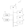
- FIG. 1 is a hardware configuration diagram of the biometric authentication device according to the present embodiment.
- the biometric authentication device 1 can be configured by incorporating a program for executing biometric authentication processing, which will be described later, into a general-purpose PC or the like.
- a biometric authentication device 1 includes a CPU (Central Processing Unit) 11, an input device 12, an output device 13, a ROM (Read Only Memory) 14, a RAM (Random Access Memory) 15, an interface (I / F). ) 16 is connected to the bus 17.
- CPU Central Processing Unit
- ROM Read Only Memory
- RAM Random Access Memory
- the input device 12 is, for example, a keyboard, a joystick, a light pen, a mouse, a touch pad, a touch panel, a trackball, and the like, and inputs various data and signals.
- the output device 13 is, for example, various displays such as an LCD (Liquid Cristal Display), a printer, and the like, and outputs an image and other information.
- LCD Liquid Cristal Display
- the ROM 14 stores a control program and table data for controlling and executing each function of the biometric authentication device 1 in addition to a program for executing biometric authentication processing executed in the biometric authentication device 1.
- the RAM 15 stores a frame buffer for the output device 13 and some application programs.
- the interface 16 is a unit for connecting to an external device such as a serial interface such as USB or a parallel interface such as Ethernet (registered trademark).
- CPU 11 controls each of these units.
- FIG. 2 is a functional block diagram of the biometric authentication device in the present embodiment.
- the biometric authentication device 1 includes a biometric image acquisition unit 21, a direction detection unit 22, a template pattern extraction unit 23, an image conversion unit 24, an authentication unit 25, and a template pattern registration unit 26.
- the biometric authentication device 1 has a computer function, and executes biometric authentication processing to be described later according to a built-in biometric authentication program.
- the biological image acquisition unit 21 acquires a user's biological image captured by the cable-equipped imaging device 100 ⁇ / b> A described with reference to FIG. 11 or the cableless imaging device 100 ⁇ / b> B described with reference to FIG. 12.
- the living body is, for example, a palm.
- the cable-equipped imaging device 100A or the cableless imaging device 100B is referred to as the imaging device 100.
- the orientation detection unit 22 detects the orientation of the living body in the biological image based on the biological image acquired by the biological image acquisition unit 21.
- the living body image is a palm image.
- the orientation detection unit 22 detects the orientation of the palm based on the middle finger portion and the wrist portion included in the palm image, for example.
- the template pattern extraction unit 23 extracts a template pattern that matches the direction detected by the direction detection unit 22 from the template pattern storage unit 30 that stores a plurality of template patterns.
- the template pattern storage unit 30 stores a template pattern in which feature information is extracted for each of a plurality of orientations of the user's living body, for example, template images in four orientations different from each other by 90 degrees.
- the feature information includes, for example, the positions, types, directions, and lengths of the end points and branch points of the veins.
- the template pattern storage unit 30 may be included in the biometric authentication device 1 or may be stored in an external storage device.
- the image conversion unit 24 converts the biological information acquired from the biological image acquired by the biological image acquisition unit 21 into a biological pattern.
- a vein image is generated by executing noise removal processing, binarization processing, and thinning processing from a palm image. Then, the position, type, direction, length, and the like of the feature points of the vein image are calculated and used as a biological pattern.
- the authentication unit 25 authenticates the user by comparing the biometric pattern converted by the image conversion unit 24 with the template pattern extracted by the template pattern extraction unit 23.
- the template pattern registration unit 26 stores the biological pattern converted by the image conversion unit 24 in the template pattern storage unit 30 in advance as a template pattern.
- FIG. 3 is a hardware configuration diagram of the imaging apparatus according to the present embodiment.
- the imaging apparatus 100 includes a light emitting unit 31, a light receiving unit 32, a CPU 33, and an interface 34.
- the light emitting unit 31 is composed of, for example, an LED (Light-Emitting-Diode), and emits irradiation light for irradiating the hand 300.
- the irradiation light is, for example, near infrared light having a wavelength near 760 nm.
- the light receiving unit 32 receives a part of the irradiation light scattered inside the hand 300 as reflected light.
- the light receiving unit 32 is an image sensor for near infrared light, for example, and includes a plurality of light receiving elements arranged in a matrix. Each light receiving element converts it into an electric signal (light receiving signal) having a signal level corresponding to the amount of reflected light.
- the CPU 33 controls turning on and off of the light emitting unit 31.
- the CPU 33 reads a light reception signal from each light receiving element included in the light receiving unit 32 and generates a vein image based on the read light reception signal for one frame. Since reduced hemoglobin flowing through veins has the property of absorbing near-infrared light, the vein part under the palm of the hand appears darker than the surrounding tissue. The pattern due to the difference in brightness becomes a vein image.
- the interface 34 is a unit for connecting to an external device such as a serial interface such as USB or a parallel interface such as Ethernet.
- an external device such as a serial interface such as USB or a parallel interface such as Ethernet.
- the interface 34 is connected to the biometric authentication device 1.
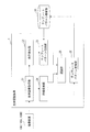
- FIG. 4 is a flowchart showing the flow of biometric authentication processing in the present embodiment.
- FIG. 5 is a diagram illustrating an example of a palm image. 6 and 7 are diagrams for explaining an example of detecting the palm orientation.
- FIG. 8 is a diagram illustrating an example of a vein image.
- the CPU 11 of the biometric authentication device 1 acquires a user's biometric image captured by the imaging device 100, for example, a palm image as shown in FIG. 5, in step S401 of FIG.
- step S402 the CPU 11 detects the direction of the living body in the living body image based on the living body image acquired in step S401.
- the orientation of the palm is detected based on, for example, the middle finger portion and the wrist portion included in the palm image.
- the palm image is scanned in the first scanning direction 60 as shown in FIG. 6, and the palm image is scanned in the second scanning direction 70 that is 90 degrees different from the first scanning direction 60 as shown in FIG.
- the orientation of the palm is detected.
- the scanning line 620 side in the first scanning direction 60 is the wrist direction.
- step S403 the CPU 11 converts the biometric pattern obtained by extracting feature information from the biometric image acquired in step S401.
- noise removal processing such as smoothing using a low-pass filter or image enhancement using a high-pass filter from a palm image, binarization processing that eliminates shading of the image, and makes it a black and white image, each included in the binary image
- a vein image as shown in FIG. 8 is generated by executing a thinning process with a line width of 1 pixel on the connected figure.
- feature points such as end points indicating vein breaks and branch points that are vein breaks are detected, and the position, type, direction, length, etc. of the feature points are calculated, To do.
- step S404 the CPU 11 extracts a template pattern that matches the direction detected in step S402 from the template pattern storage unit 30 that stores a plurality of template patterns.
- the template pattern storage unit 30 stores a template pattern in which feature information is extracted for each of a plurality of orientations of the user's living body, for example, template images in four orientations different from each other by 90 degrees.
- a biometric registration process for registering a template pattern in the template pattern storage unit 30 will be described later with reference to FIG.
- step S405 the CPU 11 authenticates the user by comparing the biometric pattern converted in step S403 with the template pattern extracted in step S404. For example, when the degree of similarity between the biometric pattern and the template pattern is equal to or greater than a predetermined threshold, the user of the biometric image acquired in step S401 is authenticated as the person registered as the template pattern extracted in step S404. To do.
- minutiae matching or pattern matching can be used. In comparison of similarity using minutia matching, first, the number of minutiae that matches between minutia (feature points) included in the template pattern and minutia included in the biometric pattern is obtained. Then, the similarity can be calculated by dividing the matching number by the number of minutiae included in the biological pattern.
- FIG. 9 is a flowchart showing the flow of the biometric registration process.
- FIG. 10 is a diagram illustrating an example of a template pattern storage unit.
- the CPU 11 of the biometric authentication device 1 acquires a user's biometric image captured by the imaging device 100, for example, a palm image, in step S901 of FIG. 9 in the same manner as in step S401 of FIG.
- step S902 the CPU 11 converts the biometric image acquired in step S901 and the biometric image having an orientation different from the biometric image into a biometric pattern from which feature information has been extracted, as in step S403 of FIG. .
- biometric images in three directions, 90 degrees, 180 degrees, and 270 degrees different from the biometric image are converted into a biometric pattern.
- step S903 the CPU 11 stores the biometric pattern converted in step S902 in the template pattern storage unit 30 as a template pattern.
- the biometric pattern “pattern 000 data” converted from the acquired biometric image, the biometric pattern “pattern 090 data” converted after changing the acquired biometric image by 90 degrees, The biometric pattern “pattern 180 data” converted after changing the biometric image by 180 degrees and the biometric pattern “pattern 270 data” converted after changing the acquired biometric image by 270 degrees are used to identify the user Stored in association with the user ID.
- one biological image may be converted into four template patterns, or four directions of biological images may be acquired and each biological image may be converted into a template pattern.
- the embodiment of the present invention described above can be realized as a function of a biometric authentication device by hardware or firmware or software on a DSP (Digital Signal Processor) board or CPU board.
- DSP Digital Signal Processor
- the biometric authentication device to which the present invention is applied is not limited to the above-described embodiment as long as the function is executed, and is configured by a plurality of devices even if it is a single device.
- the system or the integrated device may be a system in which processing is performed via a network such as a LAN or a WAN.
- a system comprising a CPU, ROM or RAM memory connected to the bus, input device, output device, external recording device, medium drive device, and network connection device. That is, a ROM or RAM memory, an external recording device, or a portable recording medium that records a software program that implements the system of the above-described embodiment is supplied to the biometric authentication device, and the biometric authentication device computer stores the program. Needless to say, this can also be achieved by reading and executing.
- the program itself read from the portable recording medium or the like realizes the novel function of the present invention
- the portable recording medium or the like on which the program is recorded constitutes the present invention
- Examples of portable recording media for supplying the program include flexible disks, hard disks, optical disks, magneto-optical disks, CD-ROMs, CD-Rs, DVD-ROMs, DVD-RAMs, magnetic tapes, and nonvolatile memory cards.
- Various recording media recorded via a network connection device such as a ROM card, electronic mail or personal computer communication can be used.
- the computer executes the program read out on the memory, thereby realizing the functions of the above-described embodiment, and an OS running on the computer based on the instructions of the program. Performs part or all of the actual processing, and the functions of the above-described embodiments are also realized by the processing.
- a program read from a portable recording medium or a program (data) provided by a program (data) provider is stored in a memory provided in a function expansion board inserted into the computer or a function expansion unit connected to the computer.
- the CPU of the function expansion board or function expansion unit performs part or all of the actual processing based on the instructions of the program, and the functions of the above-described embodiment are realized by the processing. obtain.
- the present invention is not limited to the embodiments described above, and can take various configurations or shapes without departing from the gist of the present invention.
Abstract
ユーザの生体を撮像した生体画像を取得し、取得された生体画像に基づいて生体画像における生体の向きを検出し、複数のテンプレートパターンを格納したテンプレートパターン格納部から検出された向きと一致するテンプレートパターンを抽出し、取得された生体画像から特徴情報を抽出した生体パターンに変換し、変換された生体パターンと抽出されたテンプレートパターンを照合してユーザを認証することで、静脈データの登録時と認証時とで、翳す手の向きと撮像装置の向きとが相違する場合であっても、正しい生体認証を行うことができる。
Description
本発明は、人間の生体を用いて個人認証を行うための生体認証プログラム、生体認証装置および生体認証方法に関する。
従来、人間の生体を用いて個人認証を行う生体認証技術が知られている。生体認証技術は、予め人間の生体の特徴を示す生体情報を登録しておき、この登録済みの生体情報と認証時に取得した生体情報との類似性を判断することで個人認証を行う技術である。
人間の生体には、指紋、掌紋、虹彩、網膜、顔面、静脈等、個人を識別することができる部分が多数存在する。近年のバイオメトリックス技術の進展に伴い、人間の生体の特徴を認識して、個人認証を行う生体認証装置が種々提供されている。特に、静脈は、比較的大量の個人特徴データを得られるとともに、胎児の時から生涯変わることもなく、個人認証に適している(例えば、特許文献1、2参照)。
例えば、手のひらの静脈を用いて個人認証を行う場合、静脈データの登録時および認証時において、利用者は、手のひらを生体認証装置に近づける。生体認証装置は、例えば、波長が760nm(ナノメートル)付近の近赤外線を発光し、手のひらに照射する。そして、生体認証装置は、手のひらで反射した反射光をセンサで受信する。静脈を流れる赤血球中のヘモグロビンは酸素を失っており、このヘモグロビン(還元ヘモグロビン)は、波長が760nm付近の近赤外線を吸収する。このため、手のひらに近赤外線を照射すると、静脈がある部分だけ反射が少なく、反射した近赤外線の強弱で静脈の位置を認識することができる。このような静脈を用いた生体認証技術は、例えば、銀行等の金融機関における本人認証や厳重な管理が必要な施設への入退室など、高いセキュリティが必要な分野で普及が始まっている。
また、静脈を用いた生体認証技術は、非接触の簡単な操作で認証できるというもう1つの特徴から、近年は、パーソナルコンピュータ(PC:Personal Computer)やタブレットのログイン、これらのPC等を用いたネットワーク上へのアクセス管理の用途で、パスワード代わりの用途が増加している。PC等を用いる生体認証技術には、近赤外線を発光し、反射した反射光をセンサで受信する機能を有する携帯可能な小型の撮像装置を利用することがある。図11および図12に撮像装置の例を示す。
図11は、撮像装置の一例であるケーブル付撮像装置を示す図である。
ケーブル付撮像装置100Aは、翳された手のひらに近赤外線を発光し、反射した反射光をセンサで受信する機能(画像データの撮像)を有する。ケーブル付撮像装置100Aは、図11に示すように、PC等と接続を行うためのUSB(Universal Serial Bus)オス側コネクタ110を備え、USBケーブル120等のデータ通信ケーブルを介してPC等のUSBメス側コネクタと接続され、PC等との間でデータ通信が可能である。
ケーブル付撮像装置100Aは、例えば、縦方向(Y方向)および横方向(X方向)に等間隔で配列されたCCD(Charge Coupled Device Image Sensor)、CMOS(Complementary Metal Oxide Semiconductor Image Sensor)等の撮像素子を備える。ケーブル付撮像装置100Aが撮像した画像データは、所定の位置を原点にしたX方向およびY方向の2次元データで表現される。
図12は、撮像装置の一例であるケーブルレス撮像装置を示す図である。
ケーブルレス撮像装置100Bは、近赤外線を発光し、反射した反射光をセンサで受信する機能を有する。ケーブルレス撮像装置100Bは、図12に示すように、PC等と接続を行うためのUSBオス側コネクタ110を備え、直接PC等のUSBメス側コネクタと接続され、PC等との間でデータ通信が可能である。
ケーブルレス撮像装置100Bは、例えば、縦方向(Y方向)および横方向(X方向)に等間隔で配列されたCCD、CMOS等の撮像素子を備える。ケーブルレス撮像装置100Bが撮像した画像データは、所定の位置を原点にしたX方向およびY方向の2次元データで表現される。
しかしながら、携帯可能な小型の撮像装置を利用した生体認証においては、翳す手の向きと撮像装置の向きとの関係に起因する以下のような問題点があった。
図13および図14は、ケーブル付撮像装置利用の問題点を説明するための図である。
図11を用いて説明したケーブル付撮像装置100Aは、図13および図14に示すように、PC200の側面のUSBメス側コネクタ210にUSBオス側コネクタ110を挿入することで、PC200とデータ通信可能に接続される。
例えば、静脈データ登録の際は、手300の向きとケーブル付撮像装置100Aの向きが図13に示すような配置関係であり、認証時の際は、手300の向きとケーブル付撮像装置100Aの向きが図14に示すような配置関係とあった場合、ケーブル付撮像装置100Aが撮像した画像データは、互いに90度異なる情報となる。その結果、登録時と認証時の手300が同一であっても、認証されない結果となる。
図15は、ケーブルレス撮像装置利用の問題点を説明するための図である。
図12を用いて説明したケーブルレス撮像装置100Bは、図15に示すように、PC200の側面のUSBメス側コネクタ210、220、230、240の何れかにUSBオス側コネクタ110を挿入することで、PC200とデータ通信可能に接続される。
例えば、静脈データ登録の際は、ケーブルレス撮像装置100BのUSBオス側コネクタ110をUSBメス側コネクタ210に挿入し、認証時の際は、ケーブルレス撮像装置100BのUSBオス側コネクタ110をUSBメス側コネクタ220、230、240の何れかに挿入した場合、ケーブルレス撮像装置100Bが撮像した画像データは、互いに90度、180度、または270度異なる情報となる。その結果、登録時と認証時の手300が同一であっても、認証されない結果となる。
本発明は、前述のような実状に鑑みたものであり、静脈データの登録時と認証時とで、翳す手の向きと撮像装置の向きとが相違する場合であっても、正しい生体認証を行うことが可能な、生体認証プログラム、生体認証装置および生体認証方法を提供することを目的とする。
本発明は、上記課題を解決するため、下記のような構成を採用した。
すなわち、本発明の一態様によれば、本発明の生体認証プログラムは、生体認証装置のコンピュータを、ユーザの生体を撮像した生体画像を取得する生体画像取得手段、前記生体画像取得手段によって取得された生体画像に基づいて、前記生体画像における前記生体の向きを検出する向き検出手段、複数のテンプレートパターンを格納したテンプレートパターン格納部から前記向き検出手段によって検出された向きと一致するテンプレートパターンを抽出するテンプレートパターン抽出手段、前記生体画像取得手段によって取得された生体画像から特徴情報を抽出した生体パターンに変換する画像変換手段、前記画像変換手段によって変換された生体パターンと前記テンプレートパターン抽出手段によって抽出されたテンプレートパターンを照合して前記ユーザを認証する認証手段、として機能させるための生体認証プログラムである。
また、本発明の生体認証プログラムは、前記テンプレートパターン格納部が、前記ユーザの生体の複数の向きのテンプレート画像のそれぞれについて、特徴情報を抽出したテンプレートパターンを格納することが望ましい。
また、本発明の生体認証プログラムは、前記テンプレートパターンが、前記ユーザの生体の1つの向きの生体画像から変換することが望ましい。
また、本発明の生体認証プログラムは、前記複数の向きが、互いに90度ずつ異なる4方向の向きであることが望ましい。
また、本発明の生体認証プログラムは、前記生体が、手のひらであり、前記生体画像が、手のひら画像であり、前記向き検出部が、前記手のひら画像に含まれる指部分と手首部分に基づいて、前記手のひらの向きを検出することが望ましい。
また、本発明の生体認証プログラムは、前記生体画像が、前記手のひらに照射された赤外光の反射光によって撮像された静脈画像であることが望ましい。
また、本発明の生体認証プログラムは、前記特徴情報が、前記静脈画像の端点または分岐点の位置、種類、方向、または長さを含むことが望ましい。
また、本発明の生体認証プログラムは、更に、前記画像変換手段によって変換した生体パターンを前記テンプレートパターンとして前記テンプレートパターン格納部に予め格納するテンプレートパターン登録手段として機能させることが望ましい。
また、本発明の一態様によれば、本発明の生体認証装置は、ユーザの生体を撮像した生体画像を取得する生体画像取得部と、前記生体画像取得部によって取得された生体画像に基づいて、前記生体画像における前記生体の向きを検出する向き検出部と、複数のテンプレートパターンを格納したテンプレートパターン格納部から前記向き検出部によって検出された向きと一致するテンプレートパターンを抽出するテンプレートパターン抽出部と、前記生体画像取得部によって取得された生体画像から特徴情報を抽出した生体パターンに変換する画像変換部と、前記画像変換部によって変換された生体パターンと前記テンプレートパターン抽出部によって抽出されたテンプレートパターンを照合して前記ユーザを認証する認証部とを備えることを特徴とする。
また、本発明の一態様によれば、本発明の生体認証方法は、生体認証装置において実行される生体認証方法であって、ユーザの生体を撮像した生体画像を取得し、前記取得された生体画像に基づいて、前記生体画像における前記生体の向きを検出し、複数のテンプレートパターンを格納したテンプレートパターン格納部から前記検出された向きと一致するテンプレートパターンを抽出し、前記取得された生体画像から特徴情報を抽出した生体パターンに変換し、前記変換された生体パターンと前記抽出されたテンプレートパターンを照合して前記ユーザを認証することを特徴とする。
本発明によれば、静脈データの登録時と認証時とで、翳す手の向きと撮像装置の向きとが相違する場合であっても、正しい生体認証を行うことが可能となる。
以下、本発明の実施の形態について、図面を参照しながら詳細に説明する。
図1は、本実施の形態における生体認証装置のハードウェア構成図である。
生体認証装置1は、後述する生体認証処理を実行するプログラムを汎用PC等に組み込むことによって構成することができる。
図1に示すように、生体認証装置1は、CPU(Central Processing Unit)11、入力装置12、出力装置13、ROM(Read Only Memory)14、RAM(Random Access Memory)15、インターフェース(I/F)16がバス17に接続されて構成されている。
入力装置12は、例えば、キーボード、ジョイスティック、ライトペン、マウス、タッチパッド、タッチパネル、トラックボール等であり、各種のデータや信号等を入力する。
出力装置13は、例えば、LCD(Liquid Cristal Display)等の各種ディスプレイ、プリンタ等であり、画像やその他の情報を出力する。
ROM14は、生体認証装置1において実行する生体認証処理を実行するプログラムの他、生体認証装置1の各機能を制御し実行するための制御プログラム及びテーブルデータなどを収納する。
RAM15は、出力装置13用のフレームバッファや一部のアプリケーションプログラム等を格納する。
インターフェース16は、USB等のシリアルインターフェースやイーサネット(登録商標)等のパラレルインターフェース等、外部機器と接続するためのユニットである。
CPU11は、これらの各部を制御している。
図2は、本実施の形態における生体認証装置の機能ブロック図である。
図2に示すように、生体認証装置1は、生体画像取得部21、向き検出部22、テンプレートパターン抽出部23、画像変換部24、認証部25、およびテンプレートパターン登録部26を備える。生体認証装置1は、コンピュータの機能を備えており、組み込まれた生体認証プログラムに従って後述する生体認証処理を実行する。
生体画像取得部21は、図11を用いて説明したケーブル付撮像装置100A、または図12を用いて説明したケーブルレス撮像装置100Bによって撮像したユーザの生体画像を取得する。生体は、例えば手のひらである。以下の説明では、ケーブル付撮像装置100A、またはケーブルレス撮像装置100Bを撮像装置100と称する。
向き検出部22は、生体画像取得部21によって取得された生体画像に基づいて、生体画像における生体の向きを検出する。生体が手のひらである場合、生体画像は、手のひら画像である。向き検出部22は、例えば手のひら画像に含まれる中指部分と手首部分に基づいて、手のひらの向きを検出する。
テンプレートパターン抽出部23は、複数のテンプレートパターンを格納したテンプレートパターン格納部30から向き検出部22によって検出された向きと一致するテンプレートパターンを抽出する。テンプレートパターン格納部30には、ユーザの生体の複数の向き、例えば互いに90度ずつ異なる4方向の向きのテンプレート画像のそれぞれについて、特徴情報を抽出したテンプレートパターンを格納している。特徴情報は、例えば静脈の端点や分岐点の位置、種類、方向、長さ等を含む。なお、テンプレートパターン格納部30は、生体認証装置1が備えていても良いし、外部の記憶装置に格納されていても良い。
画像変換部24は、生体画像取得部21によって取得された生体画像から特徴情報を抽出した生体パターンに変換する。例えば、手のひら画像から、ノイズ除去処理、2値化処理、および細線化処理を実行することで、静脈画像を生成する。そして、静脈画像の特徴点の位置、種類、方向、長さ等を算出し、生体パターンとする。
認証部25は、画像変換部24によって変換された生体パターンとテンプレートパターン抽出部23によって抽出されたテンプレートパターンを照合してユーザを認証する。
テンプレートパターン登録部26は、画像変換部24によって変換した生体パターンをテンプレートパターンとしてテンプレートパターン格納部30に予め格納する。
図3は、本実施の形態における撮像装置のハードウェア構成図である。
図3において、撮像装置100は、発光部31、受光部32、CPU33、およびインターフェース34を備える。
図3において、撮像装置100は、発光部31、受光部32、CPU33、およびインターフェース34を備える。
発光部31は、例えば、LED(Light Emitting Diode)で構成され、手300に照射するための照射光を発する。照射光は、例えば波長が760nm付近の近赤外光である。
発光部31から出射された照射光が手300の手のひらに照射されると、照射光は手300の内部で散乱する。受光部32は、手300の内部で散乱した照射光の一部を反射光として受光する。受光部32は、例えば近赤外光用のイメージセンサであり、マトリクス状に配列された複数の受光素子を備える。各受光素子は、反射光の光量に応じた信号レベルを有する電気信号(受光信号)に変換する。
CPU33は、発光部31の点灯および消灯を制御する。また、CPU33は、受光部32が備える各受光素子から受光信号を読み出し、読み出した1フレーム分の受光信号に基づいて静脈画像を生成する。静脈を流れる還元ヘモグロビンは近赤外光を吸収する性質があるため、手のひらの皮下にある静脈部分が周辺組織に比べて暗く写る。この明暗の差による紋様が静脈画像となる。
インターフェース34は、USB等のシリアルインターフェースやイーサネット等のパラレルインターフェース等、外部機器と接続するためのユニットであり、例えば生体認証装置1と接続する。
次に、図4乃至図8を用いて、上述の生体認証装置1が実行する生体認証処理について説明する。
図4は、本実施の形態における生体認証処理の流れを示すフローチャートである。図5は、手のひら画像の例を示す図である。図6および図7は、手のひらの向きの検出例を説明するための図である。図8は、静脈画像の例を示す図である。
生体認証装置1のCPU11は、図4のステップS401において、撮像装置100によって撮像したユーザの生体画像、例えば図5に示すような手のひら画像を取得する。
CPU11は、ステップS402において、ステップS401で取得された生体画像に基づいて、生体画像における生体の向きを検出する。生体画像が手のひら画像である場合、例えば手のひら画像に含まれる中指部分と手首部分に基づいて、手のひらの向きを検出する。例えば、図6に示すように第1走査方向60で手のひら画像を走査し、図7に示すように、第1走査方向60と90度異なる第2走査方向70で手のひら画像を走査する。走査線605における輝度曲線605bと走査線620における輝度曲線620b、および、走査線706における輝度曲線706bと走査線713における輝度曲線713bを比較することにより、手のひらの向きを検出する。上述の例では、第1走査方向60における走査線620側が手首の方向であることを検出することができる。
CPU11は、ステップS403において、ステップS401で取得された生体画像から特徴情報を抽出した生体パターンに変換する。例えば、手のひら画像から、ローパスフィルタを用いた平滑化やハイパスフィルタを用いた画像強調等のノイズ除去処理、画像の濃淡を無くして白黒画像にする2値化処理、2値画像中に含まれる各々の連結図形に対して線幅を1ピクセルにする細線化処理を実行することで、図8に示すような静脈画像を生成する。そして、静脈画像について、例えば、静脈の切れ目を示す端点、静脈の分かれ目である分岐点等の特徴点を検出し、その特徴点の位置、種類、方向、長さ等を算出し、生体パターンとする。
CPU11は、ステップS404において、複数のテンプレートパターンを格納したテンプレートパターン格納部30から、ステップS402で検出された向きと一致するテンプレートパターンを抽出する。テンプレートパターン格納部30には、ユーザの生体の複数の向き、例えば互いに90度ずつ異なる4方向の向きのテンプレート画像のそれぞれについて、特徴情報を抽出したテンプレートパターンを格納している。テンプレートパターン格納部30にテンプレートパターンを登録する生体登録処理については、図9を用いて後述する。
CPU11は、ステップS405において、ステップS403で変換された生体パターンとステップS404で抽出されたテンプレートパターンを照合してユーザを認証する。例えば、生体パターンとテンプレートパターンの類似度が予め定められた閾値以上であった場合に、ステップS401で取得した生体画像のユーザがステップS404で抽出したテンプレートパターンとして登録されている本人であると認証する。類似度の比較には、例えば、マニューシャマッチングやパターンマッチングを用いることができる。マニューシャマッチングを用いる類似度の比較では、まず、テンプレートパターンに含まれるマニューシャ(特徴点)と、生体パターンに含まれるマニューシャとの間で一致するマニューシャの個数を求める。そして、その一致する個数を、生体パターンに含まれるマニューシャの個数で割ることにより、類似度を算出できる。
次に、図9および図10を用いて、上述の生体認証装置1が実行する生体登録処理について説明する。
図9は、生体登録処理の流れを示すフローチャートである。図10は、テンプレートパターン格納部の例を示す図である。
生体認証装置1のCPU11は、図9のステップS901において、図4のステップS401と同様に、撮像装置100によって撮像したユーザの生体画像、例えば手のひら画像を取得する。
CPU11は、ステップS902において、ステップS901で取得された生体画像、および、この生体画像と異なる角度の向きの生体画像について、図4のステップS403と同様に、特徴情報を抽出した生体パターンに変換する。例えば、ステップS901で取得された生体画像に加え、この生体画像と90度、180度、および270度異なる3方向、合計4方向の生体画像を生体パターンに変換する。
CPU11は、ステップS903において、ステップS902で変換した生体パターンをテンプレートパターンとしてテンプレートパターン格納部30に格納する。例えば、図10に示すように、取得された生体画像から変換した生体パターン「パターン000データ」、取得された生体画像を90度異ならせてから変換した生体パターン「パターン090データ」、取得された生体画像を180度異ならせてから変換した生体パターン「パターン180データ」、および、取得された生体画像を270度異ならせてから変換した生体パターン「パターン270データ」を、ユーザを特定するためのユーザIDと対応付けて格納する。
なお、上述したように、1つの生体画像から4つのテンプレートパターンに変換してもよいし、4方向の生体画像を取得し、それぞれの生体画像をテンプレートパターンに変換してもよい。
以上、本発明の実施の形態を、図面を参照しながら説明してきたが、本発明が適用される生体認証装置は、前述の実施の形態に限定されない。
前述してきた本発明の実施の形態は、生体認証装置の一機能としてハードウェア又はDSP(Digital Signal Processor)ボードやCPUボードでのファームウェアもしくはソフトウェアにより実現することができる。
また、本発明が適用される生体認証装置は、その機能が実行されるのであれば、前述の実施の形態に限定されることなく、単体の装置であっても、複数の装置から構成されるシステムあるいは統合装置であっても、LAN、WAN等のネットワークを介して処理が行なわれるシステムであってもよいことは言うまでもない。
また、バスに接続されたCPU、ROMやRAMのメモリ、入力装置、出力装置、外部記録装置、媒体駆動装置、ネットワーク接続装置で構成されるシステムでも実現できる。すなわち、前述してきた実施の形態のシステムを実現するソフトェアのプログラムを記録したROMやRAMのメモリ、外部記録装置、可搬記録媒体を、生体認証装置に供給し、その生体認証装置のコンピュータがプログラムを読み出し実行することによっても、達成されることは言うまでもない。
この場合、可搬記録媒体等から読み出されたプログラム自体が本発明の新規な機能を実現することになり、そのプログラムを記録した可搬記録媒体等は本発明を構成することになる。
プログラムを供給するための可搬記録媒体としては、例えば、フレキシブルディスク、ハードディスク、光ディスク、光磁気ディスク、CD-ROM、CD-R、DVD-ROM、DVD-RAM、磁気テープ、不揮発性のメモリーカード、ROMカード、電子メールやパソコン通信等のネットワーク接続装置(言い換えれば、通信回線)を介して記録した種々の記録媒体などを用いることができる。
また、コンピュータ(情報処理装置)がメモリ上に読み出したプログラムを実行することによって、前述した実施の形態の機能が実現される他、そのプログラムの指示に基づき、コンピュータ上で稼動しているOSなどが実際の処理の一部又は全部を行ない、その処理によっても前述した実施の形態の機能が実現される。
さらに、可搬型記録媒体から読み出されたプログラムやプログラム(データ)提供者から提供されたプログラム(データ)が、コンピュータに挿入された機能拡張ボードやコンピュータに接続された機能拡張ユニットに備わるメモリに書き込まれた後、そのプログラムの指示に基づき、その機能拡張ボードや機能拡張ユニットに備わるCPUなどが実際の処理の一部又は全部を行ない、その処理によっても前述した実施の形態の機能が実現され得る。
すなわち、本発明は、以上に述べた実施の形態に限定されるものではなく、本発明の要旨を逸脱しない範囲内で種々の構成又は形状を取ることができる。
1 生体認証装置
11 CPU
12 入力装置
13 出力装置
14 ROM
15 RAM
16 インターフェース(I/F)
17 バス
21 生体画像取得部
22 向き検出部
23 テンプレートパターン抽出部
24 画像変換部
25 認証部
26 テンプレートパターン登録部
30 テンプレートパターン格納部
31 発光部
32 受光部
33 CPU
34 インターフェース(I/F)
60 第1走査方向
70 第2走査方向
100 撮像装置
100A ケーブル付撮像装置
100B ケーブルレス撮像装置
110 USBオス側コネクタ
120 USBケーブル
200 PC
210、220、230、240 USBメス側コネクタ
300 手
605、620 走査線
605b、620b 輝度曲線
706、713 走査線
706b、713b 輝度曲線
Claims (10)
- 生体認証装置のコンピュータを、
ユーザの生体を撮像した生体画像を取得する生体画像取得手段、
前記生体画像取得手段によって取得された生体画像に基づいて、前記生体画像における前記生体の向きを検出する向き検出手段、
複数のテンプレートパターンを格納したテンプレートパターン格納部から前記向き検出手段によって検出された向きと一致するテンプレートパターンを抽出するテンプレートパターン抽出手段、
前記生体画像取得手段によって取得された生体画像から特徴情報を抽出した生体パターンに変換する画像変換手段、
前記画像変換手段によって変換された生体パターンと前記テンプレートパターン抽出手段によって抽出されたテンプレートパターンを照合して前記ユーザを認証する認証手段、
として機能させるための生体認証プログラム。 - 前記テンプレートパターン格納部は、前記ユーザの生体の複数の向きのテンプレート画像のそれぞれについて、特徴情報を抽出したテンプレートパターンを格納する、
ことを特徴とする請求項1に記載の生体認証プログラム。 - 前記テンプレートパターンは、前記ユーザの生体の1つの向きの生体画像から変換する、
ことを特徴とする請求項2に記載の生体認証プログラム。 - 前記複数の向きは、互いに90度ずつ異なる4方向の向きである、ことを特徴とする請求項3に記載の生体認証プログラム。
- 前記生体は、手のひらであり、
前記生体画像は、手のひら画像であり、
前記向き検出部は、前記手のひら画像に含まれる指部分と手首部分に基づいて、前記手のひらの向きを検出する、
ことを特徴とする請求項1乃至4の何れか1項に記載の生体認証プログラム。 - 前記生体画像は、前記手のひらに照射された赤外光の反射光によって撮像された静脈画像である、ことを特徴とする請求項5に記載の生体認証プログラム。
- 前記特徴情報は、前記静脈画像の端点または分岐点の位置、種類、方向、または長さを含む、ことを特徴とする請求項6に記載の生体認証プログラム。
- 前記画像変換手段によって変換した生体パターンを前記テンプレートパターンとして前記テンプレートパターン格納部に予め格納するテンプレートパターン登録手段、
として機能させるための請求項1乃至7の何れか1項に記載の生体認証プログラム。 - 生体認証装置において、
ユーザの生体を撮像した生体画像を取得する生体画像取得部と、
前記生体画像取得部によって取得された生体画像に基づいて、前記生体画像における前記生体の向きを検出する向き検出部と、
複数のテンプレートパターンを格納したテンプレートパターン格納部から前記向き検出部によって検出された向きと一致するテンプレートパターンを抽出するテンプレートパターン抽出部と、
前記生体画像取得部によって取得された生体画像から特徴情報を抽出した生体パターンに変換する画像変換部と、
前記画像変換部によって変換された生体パターンと前記テンプレートパターン抽出部によって抽出されたテンプレートパターンを照合して前記ユーザを認証する認証部と、
を備えることを特徴とする生体認証装置。 - 生体認証装置において実行される生体認証方法であって、
ユーザの生体を撮像した生体画像を取得し、
前記取得された生体画像に基づいて、前記生体画像における前記生体の向きを検出し、
複数のテンプレートパターンを格納したテンプレートパターン格納部から前記検出された向きと一致するテンプレートパターンを抽出し、
前記取得された生体画像から特徴情報を抽出した生体パターンに変換し、
前記変換された生体パターンと前記抽出されたテンプレートパターンを照合して前記ユーザを認証する、
ことを特徴とする生体認証方法。
Priority Applications (3)
| Application Number | Priority Date | Filing Date | Title |
|---|---|---|---|
| PCT/JP2017/006952 WO2018154694A1 (ja) | 2017-02-23 | 2017-02-23 | 生体認証プログラム、生体認証装置および生体認証方法 |
| JP2019500937A JP6795677B2 (ja) | 2017-02-23 | 2017-02-23 | 生体認証プログラム、生体認証装置および生体認証方法 |
| US16/535,694 US20190362062A1 (en) | 2017-02-23 | 2019-08-08 | Biometric authentication apparatus and biometric authentication method |
Applications Claiming Priority (1)
| Application Number | Priority Date | Filing Date | Title |
|---|---|---|---|
| PCT/JP2017/006952 WO2018154694A1 (ja) | 2017-02-23 | 2017-02-23 | 生体認証プログラム、生体認証装置および生体認証方法 |
Related Child Applications (1)
| Application Number | Title | Priority Date | Filing Date |
|---|---|---|---|
| US16/535,694 Continuation US20190362062A1 (en) | 2017-02-23 | 2019-08-08 | Biometric authentication apparatus and biometric authentication method |
Publications (1)
| Publication Number | Publication Date |
|---|---|
| WO2018154694A1 true WO2018154694A1 (ja) | 2018-08-30 |
Family
ID=63253565
Family Applications (1)
| Application Number | Title | Priority Date | Filing Date |
|---|---|---|---|
| PCT/JP2017/006952 WO2018154694A1 (ja) | 2017-02-23 | 2017-02-23 | 生体認証プログラム、生体認証装置および生体認証方法 |
Country Status (3)
| Country | Link |
|---|---|
| US (1) | US20190362062A1 (ja) |
| JP (1) | JP6795677B2 (ja) |
| WO (1) | WO2018154694A1 (ja) |
Cited By (1)
| Publication number | Priority date | Publication date | Assignee | Title |
|---|---|---|---|---|
| WO2020053610A1 (en) | 2018-09-14 | 2020-03-19 | SOLOVEV, Sergei, Vladimirovich | A method for automatic contactless authentication |
Citations (4)
| Publication number | Priority date | Publication date | Assignee | Title |
|---|---|---|---|---|
| JP2002117405A (ja) * | 2000-10-05 | 2002-04-19 | Nippon Telegr & Teleph Corp <Ntt> | 掌形認証方法 |
| JP2005056004A (ja) * | 2003-08-07 | 2005-03-03 | Omron Corp | 顔照合装置、顔照合方法、および顔照合プログラム |
| WO2013076860A1 (ja) * | 2011-11-25 | 2013-05-30 | 富士通株式会社 | 生体情報照合装置、生体情報照合プログラムおよび生体情報照合方法 |
| JP2015057724A (ja) * | 2014-11-07 | 2015-03-26 | 富士通株式会社 | 生体認証装置 |
Family Cites Families (3)
| Publication number | Priority date | Publication date | Assignee | Title |
|---|---|---|---|---|
| JP2007128288A (ja) * | 2005-11-04 | 2007-05-24 | Fuji Xerox Co Ltd | 情報表示システム |
| JP4640295B2 (ja) * | 2006-09-07 | 2011-03-02 | 株式会社日立製作所 | 個人認証装置及び方法 |
| CN102483845B (zh) * | 2009-09-11 | 2018-09-04 | 富士通株式会社 | 生物体认证装置、生物体认证系统和生物体认证方法 |
-
2017
- 2017-02-23 JP JP2019500937A patent/JP6795677B2/ja active Active
- 2017-02-23 WO PCT/JP2017/006952 patent/WO2018154694A1/ja active Application Filing
-
2019
- 2019-08-08 US US16/535,694 patent/US20190362062A1/en not_active Abandoned
Patent Citations (4)
| Publication number | Priority date | Publication date | Assignee | Title |
|---|---|---|---|---|
| JP2002117405A (ja) * | 2000-10-05 | 2002-04-19 | Nippon Telegr & Teleph Corp <Ntt> | 掌形認証方法 |
| JP2005056004A (ja) * | 2003-08-07 | 2005-03-03 | Omron Corp | 顔照合装置、顔照合方法、および顔照合プログラム |
| WO2013076860A1 (ja) * | 2011-11-25 | 2013-05-30 | 富士通株式会社 | 生体情報照合装置、生体情報照合プログラムおよび生体情報照合方法 |
| JP2015057724A (ja) * | 2014-11-07 | 2015-03-26 | 富士通株式会社 | 生体認証装置 |
Cited By (1)
| Publication number | Priority date | Publication date | Assignee | Title |
|---|---|---|---|---|
| WO2020053610A1 (en) | 2018-09-14 | 2020-03-19 | SOLOVEV, Sergei, Vladimirovich | A method for automatic contactless authentication |
Also Published As
| Publication number | Publication date |
|---|---|
| JP6795677B2 (ja) | 2020-12-02 |
| JPWO2018154694A1 (ja) | 2019-08-08 |
| US20190362062A1 (en) | 2019-11-28 |
Similar Documents
| Publication | Publication Date | Title |
|---|---|---|
| JP5292821B2 (ja) | 静脈画像取得装置および静脈画像取得方法 | |
| JP4748199B2 (ja) | 静脈撮像装置および静脈撮像方法 | |
| US9197416B2 (en) | Verification apparatus, verification program, and verification method | |
| JP5130885B2 (ja) | 情報処理装置、情報処理方法およびプログラム | |
| EP2148303A1 (en) | Vein pattern management system, vein pattern registration device, vein pattern authentication device, vein pattern registration method, vein pattern authentication method, program, and vein data structure | |
| JP2009544108A (ja) | 多重生体認証のマルチスペクトル画像 | |
| CN111462379A (zh) | 一种含掌静脉和人脸识别的门禁管理方法、系统及介质 | |
| EP2148295A1 (en) | Vein pattern management system, vein pattern registration device, vein pattern authentication device, vein pattern registration method, vein pattern authentication method, program, and vein data structure | |
| JP5951817B1 (ja) | 指静脈認証システム | |
| JP2011022784A (ja) | 情報処理装置、ブロック検出方法およびプログラム | |
| JP5556663B2 (ja) | 照合装置、照合方法、及びプログラム | |
| US8270681B2 (en) | Vein pattern management system, vein pattern registration apparatus, vein pattern authentication apparatus, vein pattern registration method, vein pattern authentication method, program, and vein data configuration | |
| Chakraborty et al. | Biometric analysis using fused feature set from side face texture and electrocardiogram | |
| JP2011203822A (ja) | 生体認証装置、生体認証方法及びプログラム | |
| WO2018154694A1 (ja) | 生体認証プログラム、生体認証装置および生体認証方法 | |
| US8320639B2 (en) | Vein pattern management system, vein pattern registration apparatus, vein pattern authentication apparatus, vein pattern registration method, vein pattern authentication method, program, and vein data configuration | |
| Zayed et al. | A comprehensive survey on finger vein biometric | |
| KR101496852B1 (ko) | 지정맥 인증 시스템 | |
| JP2010181970A (ja) | 生体認証用装置、生体認証装置、生体認証システム、判別基準決定方法、生体認証方法、及びプログラム | |
| JP2010277196A (ja) | 情報処理装置、情報処理方法およびプログラム | |
| Shrotri et al. | IR-webcam imaging and vascular pattern analysis towards hand vein authentication | |
| BENzIANE et al. | Biometric technology based on hand vein | |
| JP5176556B2 (ja) | 静脈認証装置および静脈認証方法 | |
| Archana et al. | Palm Vein Authentication | |
| JP2011044102A (ja) | 生体認証装置、テンプレート登録方法、生体認証方法およびプログラム |
Legal Events
| Date | Code | Title | Description |
|---|---|---|---|
| 121 | Ep: the epo has been informed by wipo that ep was designated in this application |
Ref document number: 17897748 Country of ref document: EP Kind code of ref document: A1 |
|
| ENP | Entry into the national phase |
Ref document number: 2019500937 Country of ref document: JP Kind code of ref document: A |
|
| NENP | Non-entry into the national phase |
Ref country code: DE |
|
| 122 | Ep: pct application non-entry in european phase |
Ref document number: 17897748 Country of ref document: EP Kind code of ref document: A1 |