WO2018151272A1 - フリクション装置 - Google Patents
フリクション装置 Download PDFInfo
- Publication number
- WO2018151272A1 WO2018151272A1 PCT/JP2018/005569 JP2018005569W WO2018151272A1 WO 2018151272 A1 WO2018151272 A1 WO 2018151272A1 JP 2018005569 W JP2018005569 W JP 2018005569W WO 2018151272 A1 WO2018151272 A1 WO 2018151272A1
- Authority
- WO
- WIPO (PCT)
- Prior art keywords
- dial
- friction device
- elastic body
- rolling element
- members
- Prior art date
- Legal status (The legal status is an assumption and is not a legal conclusion. Google has not performed a legal analysis and makes no representation as to the accuracy of the status listed.)
- Ceased
Links
Images




Classifications
-
- G—PHYSICS
- G05—CONTROLLING; REGULATING
- G05G—CONTROL DEVICES OR SYSTEMS INSOFAR AS CHARACTERISED BY MECHANICAL FEATURES ONLY
- G05G1/00—Controlling members, e.g. knobs or handles; Assemblies or arrangements thereof; Indicating position of controlling members
- G05G1/08—Controlling members for hand actuation by rotary movement, e.g. hand wheels
-
- G—PHYSICS
- G05—CONTROLLING; REGULATING
- G05G—CONTROL DEVICES OR SYSTEMS INSOFAR AS CHARACTERISED BY MECHANICAL FEATURES ONLY
- G05G5/00—Means for preventing, limiting or returning the movements of parts of a control mechanism, e.g. locking controlling member
- G05G5/03—Means for enhancing the operator's awareness of arrival of the controlling member at a command or datum position; Providing feel, e.g. means for creating a counterforce
-
- H—ELECTRICITY
- H01—ELECTRIC ELEMENTS
- H01H—ELECTRIC SWITCHES; RELAYS; SELECTORS; EMERGENCY PROTECTIVE DEVICES
- H01H19/00—Switches operated by an operating part which is rotatable about a longitudinal axis thereof and which is acted upon directly by a solid body external to the switch, e.g. by a hand
- H01H19/02—Details
- H01H19/10—Movable parts; Contacts mounted thereon
- H01H19/20—Driving mechanisms allowing angular displacement of the operating part to be effective in either direction
-
- H—ELECTRICITY
- H01—ELECTRIC ELEMENTS
- H01H—ELECTRIC SWITCHES; RELAYS; SELECTORS; EMERGENCY PROTECTIVE DEVICES
- H01H3/00—Mechanisms for operating contacts
- H01H3/32—Driving mechanisms, i.e. for transmitting driving force to the contacts
- H01H3/50—Driving mechanisms, i.e. for transmitting driving force to the contacts with indexing or locating means, e.g. indexing by ball and spring
-
- H—ELECTRICITY
- H01—ELECTRIC ELEMENTS
- H01H—ELECTRIC SWITCHES; RELAYS; SELECTORS; EMERGENCY PROTECTIVE DEVICES
- H01H3/00—Mechanisms for operating contacts
- H01H3/32—Driving mechanisms, i.e. for transmitting driving force to the contacts
- H01H3/52—Driving mechanisms, i.e. for transmitting driving force to the contacts with means to ensure stopping at intermediate operative positions
Definitions
- the present disclosure maintains the relative position of two members by a frictional force, and allows both members to move relative to the frictional force when a force greater than a predetermined value is applied between the two members. More particularly, the present invention relates to a friction device having a friction mechanism disposed between both members.
- FIG. 13 shows a friction mechanism disclosed in Patent Document 1.
- the camera body 1 and the lens unit 2 correspond to the first member and the second member.
- the lens unit 2 is connected to the camera body 1 so as to be relatively rotatable.
- a resistance member (elastic body) 22 is interposed between the camera body 1 and the lens unit 2.
- the resistance member 22 generates a rotational resistance, that is, a frictional force between the connecting portions of the camera body 1 and the lens unit 2 so that the lens unit 2 is releasably held at the rotated position. That is, the resistance member 22 is disposed between an arcuate circumferential groove 21 provided in the lens unit 2 and an inclined surface 20 provided on the camera body end side using an O-ring.
- FIG. 14 shows the click means employed in the operation dial (dial switch) disclosed in Patent Document 2.
- This operation dial includes a switch display plate 22 displaying a plurality of indication positions on the circumference, and a dial 30 rotatably supported by a support member 42.
- the dial 30 is rotated and displayed on the dial.
- the moderation member 52 provided in the dial is fitted into the groove 46 provided in the arc-shaped rib 44 on the support member side, so that the rotational position of the dial is maintained.
- the dial 30 includes a cylindrical member 50 that holds the moderation member 52 and an urging spring 54 that urges the moderation member 52 in the outer circumferential direction.
- the moderation member 52 is a rod having both ends formed in a spherical shape having a larger outer diameter than the other portions.
- the moderation member 52 slides along the rib 44 during dial rotation, and the corresponding groove 46 among the plurality of grooves 46.
- the spring 52 swings around the spherical end contacting the spring by the biasing force of the spring 52, and the side surface of the end of the moderation member hits the support 50 in a senseable manner.
- the resistance member which is an elastic body
- the friction mechanism is likely to stick the resistance member to the other side, which is a circular groove or an inclined surface, and the next time the lens unit is moved. It becomes quite hard and requires a lot of power. This point becomes more prominent as the resistance member becomes thicker.
- a frictional force or resistance is obtained by adhesive grease instead of the resistance member, it is difficult to maintain a stable frictional force and it is easily affected by temperature.
- the click means of Document 2 aims to improve the operational feeling and make it possible to determine the rotational position of the dial without visual observation.
- the moderation member is formed at the spherical end and is supported by the urging force. When fitted in the groove on the member side, the angle is changed to make it easier to detect a hitting sound or the like.
- this click means a plurality of grooves are provided only at a predetermined interval, that is, at a place where the moderation member is fitted and held, so the click feeling becomes intermittent and lacks in operability. Can be adjusted by rotating the motor, but the safety of the automobile can be improved.
- the distance between the grooves is constant, if the number of grooves increases, it is difficult to understand unless the rotational position is visually observed.
- an object of the present invention is to prevent the above-described sticking phenomenon to the elastic body as a friction mechanism and maintain good operability. Further, in at least some embodiments of the present invention, a click feeling with high added value can be easily obtained together with an excellent operation feeling when the click means is incorporated. Moreover, in at least some embodiments of the present invention, it is an object to provide a rotary or slide type operating member employing them. Other objects of at least some embodiments of the present invention will become apparent in the following description.
- At least some embodiments of the present invention provide a first member (1, 1A), a second member (2, 2A), and the two members relatively against the friction force.
- a friction device having a friction mechanism (3) disposed between the two members so as to be movable, wherein the friction mechanism is interposed between the two members so as to generate the frictional force.
- It has an elastic body (30) attached to the first member, and a rolling element (35) that is rotatably supported by the second member and rolls on the elastic body.
- the elastic body is preferably an O-ring shape, but is not limited thereto.
- the elastic body may be formed of a straight or curved elastic plate material, and a rolling element such as a cylinder, cylinder, or sphere may be in contact with the side surface of the plate material while linearly moving or bending.
- the elastic body includes an O-ring
- the rolling element includes a substantially spherical or cylindrical roller.
- the roller may be arranged so as to be rotatable with respect to the arrangement space of the corresponding member.
- the roller may be rotatably supported via a pin or a support shaft.
- at least some embodiment of this invention is a moderation surface part which is provided in the said 1st member in any one of the said structures, and forms the concave (4b, 5a) and the convex (4a, 5b) alternately.
- a click means (7, 7A) comprising a contact member (6, 35) provided on the second member and elastically supported to contact the moderation surface portion. It is characterized by being.
- “recesses and protrusions are alternately formed” means that the moderation surface portion has a continuous wave shape in which a valley portion and a mountain portion are alternately formed in a cross section.
- the rolling element also serves as the contact member.
- the rolling element as the contact member is elastically supported by the elastic body on which the rolling element rolls.
- the rolling elements may be rotated via pins or support shafts as shown in each embodiment, or the pins and support members may be rotated as shown in the second modification. It is preferable that the shaft is rotated about the center axis, and that it can be moved slightly in a direction away from the recess via a pin or a support shaft.
- the second member has a groove (25) extending so as to form an angle in the moving direction of the elastic body with respect to the rolling element, and the rolling element extends in the groove extending direction.
- a configuration in which the second member is rotatably supported by a support shaft (37) slidably received is preferable.
- the contact member may be formed by a part (6a) of the leaf spring (6).
- At least some embodiments of the present invention are characterized in that, in any of the configurations having the moderation surface portion, the pitch between the concave and the convex is non-uniform.
- the shape feature of the concave 5b is specified, and the position after the operation of the first member can be easily grasped by the change in the sense of moderation of the unevenness.
- At least some embodiments of the present invention are characterized in that at least one of the depth of the concave and the height of the convex is non-uniform in any of the configurations having the moderation surface portion.
- the shape of the convex 5a and the concave 5b constituting the moderation surface portion in FIG. if the depth of the recess 5b is gradually decreased along the circumferential direction), that is, if the depth of the protrusion 5a is gradually decreased, An effect similar to that obtained when the pitch is changed is obtained.
- one of the two members is a rotary operation member that is rotatable with respect to the other.
- One is a sliding operation member that is slidable relative to the other.
- the rolling element that is rotatably supported by the second member By using a rolling element that is rotatably supported by the second member, the sticking phenomenon of the elastic body described above, that is, the strong resistance feeling that occurs when it is moved for the first time after a long time has not passed can be greatly relieved. Good movement can be maintained.
- the rolling element that has become rotatable is more elastic than the static friction force received when a non-rolling member is applied to the elastic body as in Patent Document 1. It is because the one that hits becomes a small resistance.
- the elastic body includes an O-ring and the rolling element includes a substantially cylindrical or spherical roller
- the elastic body includes an O-ring and the rolling element includes a simple spherical or cylindrical roller. It becomes a structure and implementation becomes easy.
- the click means in the process in which the first member is moved against the frictional resistance of the friction mechanism with respect to the second member, the click means acts to feel a sense of moderation due to the continuous concave and convex. Obtained and good feeling can be imparted. Since this click means is based on the premise that the first member receives elastic force from the elastic body when moving against the frictional resistance of the elastic body, the difference in unevenness is absorbed by the elastic body and the rolling element is It can also serve as a contact member.
- the rolling element also serves as the abutting member
- the abutting member on the other side of the moderation surface portion is replaced by the rolling element, so that not only the configuration is simplified but also the click means
- the moderation feeling is also a novel feeling.
- the support shaft of the rolling element is received in the groove of the second member, the support shaft slides in the groove according to the uneven step, so that the resistance at the time of relative movement between the first member and the second member Can be reduced.
- the abutting member is formed by a part of a leaf spring, there is an advantage that the number of members can be suppressed as compared with a configuration in which a spherical body generally adopted conventionally is biased by a coil spring.
- the operator can The position of one member relative to the second member can be roughly grasped.
- the first member is an example of an operation dial
- the dial when the dial is rotated, the position of the dial after rotation can be roughly grasped by a change in the sense of moderation of the unevenness.
- the grasping accuracy is increased by the operator learning according to the frequency of use.
- the pitch is changed by replacing with the pitch of the concave and convex or by further changing with the pitch. The same effect can be obtained.
- one of the two members is a rotary operation member that is rotatable with respect to the other, or in an embodiment in which one of the two members is a slide operation member that is slidable with respect to the other, an operation dial or the like
- a rotary operation member or a slide operation member such as an operation knob
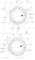
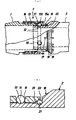
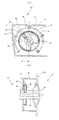
- the operation dial which concerns on 1st Embodiment of this invention is shown, (a) is a schematic external view in an assembly state, (b) is a schematic external view in a decomposition
- 2A is a cross-sectional view taken along line AA in FIG. 2
- FIG. 2B is a cross-sectional view taken along line BB in FIG.
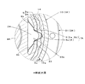
- A) is the C section enlarged view of Fig.3 (a)
- (b) is the D section enlarged view of FIG.3 (b).
- FIG. 1 and FIG. 2 of the literature 1 disclose the friction mechanism disclosed by patent document 1.
- FIG. 1 and FIG. 2 of the literature 2 disclose the click means and the operation dial (FIG. 1 and FIG. 2 of the literature 2) disclosed by patent document 2.
- FIG. 1 and FIG. 2 of the literature 2 disclose the click means and the operation dial.
- this operation dial is for controlling the heater of a vehicle similar to that in Document 2, and the friction force of the friction mechanism 3 in which the dial 1 is interposed between the two members with respect to the housing 2.
- the dial 1 is rotated as shown in FIG. 2A, and the mark 19 displayed on the dial is used as a wind direction adjustment displayed on the display board 9 as a plurality of designated positions 9 a to 9.
- the rotational position of the dial 1 is held so as to be switchable for each indicated position, and a device mechanism (not shown) is connected to the dial 1 as shown in FIG. It operates corresponding to the designated positions 9a to 9e via the rotor 8.
- FIG. 2B shows an example of a display plate 9A for air volume adjustment as a modification of the display board 9, and the air volume increases as the plurality of designated positions 9a to 9g move from left to right.
- the display plates 9 and 9A are provided, for example, along the panel side on which the housing 2 is mounted.
- the friction mechanism 3 is an O-ring 30 that is an elastic body positioned on the dial 1 (first member), and is rotatably disposed on the housing 2 (second member) so as to contact a part of the O-ring 30.
- the roller 35 is a contact member.
- the O-ring 30 may be provided on the housing 2 side and the roller 35 may be provided on the dial 1 side.
- the dial 1 has a generally cap shape as shown in FIGS. 3 and 5, and the outer peripheral surface 10 of the side peripheral wall in the cap shape is inclined from the upper and lower middle toward the end surface, and is easily formed with a finger. Is provided on the end face.
- the mark 19 has a configuration in which paint or the like is attached to the recess 10a provided on the end face, but printing or the like may be used.
- the inner peripheral surface 11 of the side peripheral wall has a circular shape with a predetermined depth, and the connecting cylinder 13 protrudes from the inner center, and the inner peripheral surface 11 protrudes from the connecting cylinder 13 with a gap therebetween.
- a cylindrical portion 15, a step portion 16 provided on the inner peripheral side of the cylindrical portion 15 so that the protruding length is smaller than the outer peripheral side of the cylindrical portion 15, and a hollow portion provided around the rising of the connecting cylinder 13 18 etc.
- a gap in which the O-ring 30 and the roller 35 can be disposed is set between the inner peripheral surface 11 and the cylindrical portion 15.
- an O-ring 30 is positioned and arranged in a state of being pressed against the inner peripheral surface 11, and a roller 35 is rotatably supported on the housing 2 side.
- a recess 12a is provided in which the upper portion can be loosely fitted with a margin.
- the O-ring 30 is made of rubber or a soft resin material.
- a moderation surface portion 4 is formed on the outer peripheral surface of the flange portion 15.
- the moderation surface portion 4 constitutes the click means 7 together with the roller 35. That is, the moderation surface portion 4 is formed with the convexes 4a and the concaves 4b alternately and continuously, and the pitch of the concaves 4b and the convexes 4a, or the convexes 4a and the concaves 4b, that is, from the apex of the convexes 4a to the center of the concaves 4b. Is gradually changing along the circumferential direction. In this example, as shown in FIG. 3B, these pitches are set so as to gradually increase from the base point 4c on the outer peripheral surface of the cylindrical portion 15 in the clockwise direction.
- this click means 7 for example, when the dial 1 is rotated in the clockwise direction from the state of FIG. 3B, the moderation feeling gradually increases, and conversely, the dial 1 is in the counterclockwise direction. When it is rotated, the moderation becomes gradually weaker.
- the housing 2 has a substantially bottomed cylindrical shape as shown in FIGS. 3 and 6, and the outer peripheral surface 20 has a flange 21 projecting substantially in the middle of the upper and lower sides, and gradually increases in the upward direction above the flange 21.
- a three-step staircase shape of a large-diameter lower peripheral portion 22, an intermediate peripheral portion 23, and a small-diameter upper peripheral portion 24 is formed so as to have a small diameter.
- An end face 22 a of the large-diameter lower peripheral portion 22 (a surface facing upward due to a difference in diameter between the large-diameter lower peripheral portion 22 and the intermediate peripheral portion 23) can receive the lower end of the dial 1.
- the intermediate peripheral portion 23 faces or slidably contacts the inner peripheral surface 11 of the dial 1 such that a portion of the housing 2 above the end surface 22a is rotatably fitted inside the cap-shaped dial 1.
- An end surface 23a of the intermediate peripheral portion 23 (a surface facing upward due to a difference in diameter between the intermediate peripheral portion 23 and the small-diameter upper peripheral portion 24) can receive and hold the O-ring 30 together with the small-diameter upper peripheral portion 24. .
- the small diameter upper peripheral portion 24 is formed with a recess 24b configured such that a part thereof is notched and is flush with the end surface 23a.
- a small concave groove 25 for attaching the roller 35 is provided on the bottom surface of the recess 24b so as to extend in the radial direction.
- the groove 25 extends to a part of the end face 23a.
- an annular recess portion 26 into which the cylindrical portion 15 on the dial 1 side is rotatably fitted and a through hole 27 provided in the center and penetrating vertically are provided. It has been.
- An O-ring 31 having a smaller diameter than the O-ring 30 is disposed between the inner peripheral surface of the annular recess 26 and the inner peripheral surface of the cylindrical portion 15.
- the upper and lower portions of the through-hole 27 are formed in a large-diameter hole 27a whose upper side is formed in a step shape that is one step larger and whose lower side is larger in diameter than the intermediate portion.
- the dial 1 and the housing 2 are assembled with, for example, an O-ring 30 on the dial 1, and a small-diameter O-ring 31 and a roller 35 on the housing 2. From the attached state, they are overlapped with each other and assembled together via the rotor 8.
- the O-ring 30 is pushed and pressed to the vicinity of the inner bottom surface 12 while being pressed against the inner peripheral surface 11 of the dial 1 to be positioned and held.
- the O-ring 31 is held in a state of being in pressure contact with the inner peripheral surface of the annular recess 26 of the housing 2.
- the O-ring 31 is thinner than the O-ring 30, and the sticking phenomenon described above is difficult to occur.
- the roller 35 is made of resin and has a mounting hole 35a provided at the center and extending from the lower end surface to the front of the upper end, and a pin-shaped support shaft 37 that is pressure-bonded to the mounting hole 35a. And the roller 35 is assembled
- the rotor 8 is inserted into the housing 2 and the male screw provided on the upper side of the rotor 8
- the part 8a is rotatably connected by being screwed with the female thread part 13a of the connecting cylinder 13 of the dial, and is assembled as an operation dial.
- the operation dial is excellent in the following points in the above assembled state.
- the supported roller 35 is brought into contact.
- the dial rotates as the roller 35 rolls on the O-ring 30. For this reason, in this structure, even when the sticking phenomenon described in the above problem, that is, when the dial 1 has not been moved for a long period of time, the O-ring 30 is rotatably supported in the next rotation operation.
- the elastic body is the same O-ring 30 as the conventional one, and the roller 35, which is a rolling element, has a simple shape such as a roughly spherical shape, a cylindrical shape, a cylindrical shape, etc., so that the cost increase is minimized. It becomes easy to implement with a limit. Further, since the roller 35 only needs to be rotatably disposed in the recess 24b in which a part of the small-diameter upper peripheral portion 24 is cut out, the assembly is easy and the configuration is simple.
- the click means 7 acts to make the convex 4 a and the concave 4 b of the continuous moderation surface portion 4
- the accompanying feeling of moderation can be obtained and good feeling can be imparted.
- the click means 7 substitutes for the roller 35 constituting the friction mechanism 3 as a contact member on the other side with respect to the moderation surface portion 4, so that the structure can be simplified.
- the moderation feeling of the click means 7 is also a novel feeling.
- the moderation surface portion 4 is on the outer peripheral surface of the cylindrical portion 15, and the distance from the apex of the convex 4a to the center of the concave 4b, that is, the pitch between the concave 4b and the convex 4a is circumferential. Therefore, when the dial 1 is rotated, the position of the dial after the rotation can be easily grasped by the change in the sense of moderation of the unevenness.
- an operator such as a driver can rotate the dial 1 accurately to switch the designated positions 9a to 9e to the intended designated position without having to visually check. Yes.
- the switching accuracy becomes higher when the operator learns a change in moderation according to the frequency of use. Therefore, the usability and safety of the device used can be improved as the operation member.
- the pitch of the recesses 4b and the height of the protrusions 4a are changed such that the pitch is non-uniform, or at least one of the depth of the recesses 4b and the height of the protrusions 4a is changed gradually or stepwise along the direction away from the base point 4c. It is also effective to make the thickness non-uniform.
- this point is, for example, the direction of the depth of the concave 4b and / or the height of the convex 4a away from the base point 4c as the shape of the convex 4a and the concave 4b constituting the moderation surface portion 4 in FIG.
- the depth of the concave 4b By gradually changing along the (circumferential direction in the example of the figure), specifically, by forming the depth of the concave 4b gradually shallower, or by gradually lowering the height of the convex 4a, The same effect as in the case of the convex and concave pitches described above can be obtained.
- a slide operation member such as an operation knob (this operation member is a slide lever or the like as disclosed in Japanese Patent Laid-Open No. 10-86634)
- this operation member is a slide lever or the like as disclosed in Japanese Patent Laid-Open No. 10-86634
- the moderation surface portion is formed in the straight plate portion, and the pitch or height of the recesses and projections corresponding to the recesses 4b and the projections 4a is gradually changed along the linear direction, or The depth is not uniform.
- FIGS. 7 to 11 the operation dial is an example having different click means 7A compared to the first embodiment.
- the same or similar parts as those in the first embodiment described above are denoted by the same reference numerals, and the changes are clarified while omitting duplicate descriptions as much as possible.
- 7 and 8 correspond to FIGS. 1 and 3 of the first embodiment
- FIGS. 10 and 11 correspond to FIGS. 6 and 7 of the first embodiment.
- FIG. 2 is also used for the second embodiment because it is the same schematic top view.
- the operation dial of the second embodiment includes a dial 1A corresponding to the dial 1, a housing 2A corresponding to the housing 2, and a rotor 8A corresponding to the rotor 8 as main members.
- the friction mechanism 3 described above is provided between the dial 1A and the housing 2A, and a click means 7A different from the click means 7 of the first embodiment is provided.
- the click means 7A includes an annular member 5 having a moderation surface portion 4 formed on the dial 1A and alternately forming protrusions 5a and recesses 5b on the inner peripheral surface, and an annular member attached to the housing 2A. 5 and a leaf spring 6 including a contact member that contacts the recess 5b.
- the saddle dial 1 ⁇ / b> A has a large-diameter inner peripheral surface 14 in which the opening side of the inner peripheral surface 11 is formed one step larger than the dial 1.
- the large-diameter inner peripheral surface 14 is provided with a plurality of engaging recesses 14a at equal intervals.
- An annular member 5 is attached to the large-diameter inner peripheral surface 14.
- the annular member 5 has a ring shape and is provided on the outer peripheral surface and functions as a moderation surface portion similar to the moderation surface portion 4 provided on the inner peripheral surface.
- the projections 5a and the recesses 5b are formed alternately and continuously.
- the pitch between the concave 5b and the convex 5a, or the pitch between the convex 5a and the concave 5b, that is, the distance from the apex of the convex 5a to the center of the concave 5b gradually changes along the circumferential direction.
- these pitches are set to gradually increase from the base point 5c of the outer peripheral surface of the annular member 5 in the clockwise direction as shown in FIG. 8B. Yes. Therefore, the click means 7A, like the click means 7, for example, when the dial 1A is rotated in the clockwise direction from the state of FIG. Rotation in the counterclockwise direction gradually weakens the sense of moderation.
- the eaves housing 2 ⁇ / b> A has a leaf spring 6 provided corresponding to the annular member 5.
- the leaf spring 6 includes a substantially U-shaped engaging portion 6a (contact member) provided in the middle as shown in FIG. 9, and locking pieces 6b and 6b extending on both sides of the engaging portion 6a. Consists of.
- the housing 2 ⁇ / b> A has an opening 20 a formed by cutting out a part below the flange 21 of the outer peripheral surface 20.
- a cavity 28 is provided in the flange 21 and the large-diameter lower peripheral portion 22 and the intermediate peripheral portion 23 from the bottom upward corresponding to the intermediate portion of the opening 20a.
- the cavity 28 has a size corresponding to the leaf spring 6.
- a small window 23 b is provided on the intermediate peripheral portion 23 on the end face 22 a side, and communicates with the cavity 28 from the small window 23 b.
- the engaging portion 6a protrudes outward from the small window 23b, and the locking piece portions 6b on both sides are locked to the corresponding portions of the cavity 28. Yes.
- the click means 7A acts and the engaging portion 6a of the leaf spring 6 becomes the annular member 5.
- the touch accompanying the contact with the projections 5a and 5b is obtained, and a good feeling can be imparted.
- the rotor 8 ⁇ / b> A corresponding to the rotor 8 of the above form has a shape in which a part of the peripheral portion is cut away corresponding to the cavity 28.
- the click means 7 of the first embodiment may be provided in addition to the click means 7A, so that a sense of moderation by the two click means 7 and 7A can be obtained.
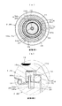
- Modification 1 of FIG. 12A shows a configuration in which a plurality of rollers 35 as contact members of the above-described form are provided. That is, in the housing 2 (2A), three recesses 24b are provided at equal intervals in the small-diameter upper peripheral portion 24. In each recess 24b, the above-described roller 35 is rotatably disposed via a support shaft 37 that fits into the groove 25 (see FIG. 4A).
- Modification 2 of FIG. 12 shows an upper shaft portion 38b as a support shaft 38 of the roller 35 with respect to a lower shaft portion 38a fitted to the groove 25 as compared with the support shaft 37 of each form. Is formed in a small diameter.
- the support shaft 38 has a small diameter upper shaft portion 38b rotatably fitted in a mounting hole 35b provided in the roller 35. The point is that the roller 35 is rotatably supported with respect to the support shaft 38.
- the present invention is not necessarily provided with all the configurations described in the embodiment, and details are described with reference to the above-described embodiments and modifications. Can be further modified and deployed.
- the O-ring 31 of each embodiment may be omitted and simplified, or the resistance force may be changed by sequentially changing the height of each protrusion 4a, 5a and the depth of each recess 4b, 5b. May be.
- the elastic body may be a square ring or an X ring other than the O ring.
- a slide type operation knob may be used instead of the operation dial.
- the contact member may be a spring material such as a coil spring in addition to the leaf spring.
- the friction device of the present invention can be applied to members in various fields other than the rotary operation member and the slide operation member, and there is no limitation in use.
Landscapes
- Physics & Mathematics (AREA)
- General Physics & Mathematics (AREA)
- Engineering & Computer Science (AREA)
- Automation & Control Theory (AREA)
- Mechanical Control Devices (AREA)
- Rotary Switch, Piano Key Switch, And Lever Switch (AREA)
Abstract
【課題】相対的に変位可能な2つの部材と、両部材間に介在して摩擦力によって両部材の相対的な位置を維持するフリクション機構とを有するフリクション装置において、摩擦力を発生させる弾性体に対する貼り付け現象を防いで良好な操作性を常に得られると共に、クリック手段を組み込む場合に優れたクリック感も得られ易くする。 【解決手段】ダイヤル(1)及びハウジング(2)の間に介在するフリクション機構(3)は、ダイヤル(1)に配設されたOリング等の弾性体(3)と、ハウジング(2)に回転自在に支持されて弾性体(3)上を転動するローラー等の転動体35とを有する。
Description
本開示は、2つの部材の相対的な位置を摩擦力によって維持すると共に、所定値以上の力が両部材の間に加わったときに摩擦力に抗して両部材を相対的に移動可能とするべく両部材の間に配置されたフリクション機構を有するフリクション装置に関する。
図13は特許文献1に開示のフリクション機構を示している。この例では、カメラ本体1及びレンズ部2が上記の第1部材及び第2部材に対応している。このレンズ部2は、カメラ本体1に対し相対的に回転可能に連結される。カメラ本体1及びレンズ部2の間には、抵抗部材(弾性体)22が介在されている。抵抗部材22は、カメラ本体1及びレンズ部2の連結部相互間に回転抵抗つまり摩擦力を生じさせ、レンズ部2が回転後の位置に解除可能に保持されるようにする。すなわち、抵抗部材22は、Oリングが用いられて、レンズ部2に設けられた円弧状の周回溝21と、カメラ本体端側に設けられた傾斜面20との間に配設されている。
また、図14は特許文献2に開示された操作ダイヤル(ダイヤル式スイッチ)に採用されたクリック手段を示している。この操作ダイヤルは、円周上に複数の指示位置を表示したスイッチ表示板22と、支持部材42に回転可能に軸支されたダイヤル30とを備え、ダイヤル30を回転させて該ダイヤルに表示されたマーク31を指示位置に整合させたときに該ダイヤルに設けられた節度部材52が支持部材側の円弧状リブ44に設けられた溝46に嵌合することでダイヤルの回転位置が保持される。ダイヤル30は、節度部材52を保持する筒部材50と、節度部材52を外周方向に付勢する付勢バネ54とを有している。節度部材52は、両端部が他の部分より外径の大きな球状に形成されている棒であり、ダイヤル回転時にリブ44に沿って摺動して、複数の溝46のうち、対応する溝46に嵌合するときはバネ52の付勢力により該バネと接する球状の端部を中心に首振りし、節度部材端部の側面が支持部50を感知可能に打撃する。
上記した文献1のフリクション機構では、弾性体である抵抗部材がレンズ部側の周回溝とカメラ本体端側の傾斜面との間に挟まれた状態に配置されている。このため、このフリクション機構は、例えば、レンズ部の動かない時間が長くなると、抵抗部材が周回溝や傾斜面である相手側に対し貼り付き易くなり、次にレンズ部を動かそうとするときにかなり硬くなって大きな力が必要となる。この点は抵抗部材が太くなるほど顕著となる。また、この対策例として、抵抗部材に代えて摩擦力や抵抗を粘着グリスにより得る構成だと、安定した摩擦力を維持し難く温度の影響も受け易くなる。
また、文献2のクリック手段は、操作フィーリングの向上と目視によらずダイヤルの回転位置を判断可能にすることを目的とし、節度部材が球状の端部に形成されることで付勢力により支持部材側の溝に嵌まる際、角度が変化して打撃音等を感知し易くした構成である。しかし、このクリック手段では、複数の溝が所定間隔、つまり節度部材を嵌合し保持する箇所だけに設けられているためクリック感が間欠的となって操作性に欠け、また、目視せずダイヤルを回転し調整できることは自動車の安全性向上に繋がるが、溝同士の間隔が一定となっているため溝が多くなると回転位置が目視しないと分かり難くなる。
そこで、本発明の目的は、フリクション機構として弾性体に対する上記した貼り付け現象を防いで良好な操作性を維持されるようにする。また、本発明の少なくともいくつかの実施形態では、クリック手段を組み込む場合に優れた操作フィーリングと共に付加価値の高いクリック感が容易に得られるようにする。また、本発明の少なくともいくつかの実施形態では、それらを採用した回転式やスライド式の操作部材を提供することにある。本発明の少なくともいくつかの実施形態における、他の目的は以下の内容説明のなかで明らかにする。
上記目的を達成するため本発明の少なくともいくつかの実施形態は、第1部材(1,1A)と、第2部材(2,2A)と、摩擦力に抗して前記両部材を相対的に移動可能とするべく前記両部材の間に配置されたフリクション機構(3)とを有するフリクション装置であって、前記フリクション機構が、前記摩擦力を発生させるべく前記両部材の間に介在するように前記第1部材に取り付けられた弾性体(30)と、前記第2部材に回転自在に支持されて前記弾性体上を転動する転動体(35)とを有していることを特徴としている。ここで、弾性体としては、Oリング形状が好ましいが、それに限定されない。例えば、弾性体は、直線や湾曲した弾性板材で形成し、該板材の側面に円柱、円筒、球状等の転動体を直線移動や湾曲移動しつつ接触する構成でもよい。
本発明の少なくともいくつかの実施形態は、上記構成において、前記弾性体がOリングを含むと共に、前記転動体が概略球状ないしは円柱状のローラーを含むことを特徴とする。ここで、ローラーは、対応部材の配置空間に対して回転自在に配置されておればよいが、各形態に示したごとくピンや支軸を介して回転自在に支持するようにしても差し支えない。
また、本発明の少なくともいくつかの実施形態は、上記構成のいずれかにおいて、前記第1部材に設けられて凹(4b,5a)と凸(4a,5b)を交互に形成している節度面部(4,5)と、前記第2部材に設けられて前記節度面部に当接するべく弾発支持された当接部材(6,35)とを備えるクリック手段(7,7A)を更に有していることを特徴とする。ここで、『凹と凸を交互に形成している』とは、節度面部が断面で谷部と山部を交互に形成した連続した波形状となっていることである。
また、本発明の少なくともいくつかの実施形態は、上記構成のいずれかにおいて、前記第1部材に設けられて凹(4b,5a)と凸(4a,5b)を交互に形成している節度面部(4,5)と、前記第2部材に設けられて前記節度面部に当接するべく弾発支持された当接部材(6,35)とを備えるクリック手段(7,7A)を更に有していることを特徴とする。ここで、『凹と凸を交互に形成している』とは、節度面部が断面で谷部と山部を交互に形成した連続した波形状となっていることである。
本発明の少なくともいくつかの実施形態は、上記構成において、前記転動体が前記当接部材を兼ねていることを特徴とする。この構成では、転動体がその上を転動している弾性体によって、当接部材としての転動体が弾発支持されている。また、当接部材の負荷が過剰にならないようにするため、各実施形態に示したごとく転動体がピンや支軸を介して回転されるようにしたり、変形例2に示したごとくピンや支軸を中心軸として回転されるようにしたり、更にピンや支軸を介して凹から離れる方向に若干移動可能にすることが好ましい。例えば、前記第2部材は、前記転動体に対する前記弾性体の移動方向に角度をなすように延在する溝(25)を有し、前記転動体は、前記溝に該溝の延在方向に摺動可能に受容された支軸(37)を介して前記第2部材に回転自在に支持された構成が好ましい。また、前記当接部材が板ばね(6)の一部(6a)にて形成されてもよい。
また、本発明の少なくともいくつかの実施形態は、上記の節度面部を有する構成のいずれかにおいて、前記凹と前記凸のピッチが不均一であることを特徴とする。この点は、図3(b)や図5(a)に例示した節度面部4を構成している凸4aと凹4b、更に図8(b)に例示した節度面部を構成している凸5aと凹5bの形状特徴を特定したものであり、第1部材の操作後の位置が凹凸の節度感の変化により把握し易くなるようにしたものである。
また、本発明の少なくともいくつかの実施形態は、上記の節度面部を有する構成のいずれかにおいて、前記凹の深さと前記凸の高さの少なくとも一方が不均一であることを特徴とする。この点は、例えば図8(b)において節度面部を構成している凸5aと凹5bの形状を、凹5bの深さ又は/及び凸5aの高さを、基点5cから離れる方向(同図の例では周方向)に沿って徐々に変化させるように、つまり凹5bの深さを徐々に浅く形成したり、凸5aの高さを徐々に低く形成するように変形すると、凸と凹のピッチを変化させた場合と同様な作用が得られるようにしたものである。
また、本発明の少なくともいくつかの実施形態は、上記の節度面部を有する構成のいずれかにおいて、前記凹の深さと前記凸の高さの少なくとも一方が不均一であることを特徴とする。この点は、例えば図8(b)において節度面部を構成している凸5aと凹5bの形状を、凹5bの深さ又は/及び凸5aの高さを、基点5cから離れる方向(同図の例では周方向)に沿って徐々に変化させるように、つまり凹5bの深さを徐々に浅く形成したり、凸5aの高さを徐々に低く形成するように変形すると、凸と凹のピッチを変化させた場合と同様な作用が得られるようにしたものである。
また、本発明の少なくともいくつかの実施形態は、上記構成のいずれかにおいて、前記両部材の一方が他方に対して回転可能な回転式操作部材であることを特徴とし、または、前記両部材の一方が他方に対してスライド移動可能なスライド式操作部材であることを特徴とする。
本発明では、第1部材と第2部材とを相対的に動かすときに両部材間に介在された弾性体の摩擦力に抗して移動させるフリクション機構として、第1部材側の弾性体に対し第2部材に回転自在に支持された転動体を用いることにより、上記した弾性体の貼り付き現象、つまり動かさない時間が長く経過した後、最初に動かすときに生じる強い抵抗感を大幅に緩和でき良好な移動を維持できる。その理由は、貼り付きによる抵抗力を低減する上で、特許文献1のごとく非転動の部材を弾性体に当てたときに受ける静摩擦力に比べて、回転自在となった転動体を弾性体に当てる方が小さな抵抗力となるからである。
前記弾性体がOリングを含むと共に、前記転動体が概略円柱状ないしは球状のローラーを含む実施形態では、弾性体がOリング、転動体もシンプルな概略球状ないしは円柱状のローラーからなるため、簡易構成となって実施容易となる。
クリック手段を有する実施形態では、第1部材が第2部材に対しフリクション機構の摩擦抵抗に抗して移動される過程において、クリック手段が作用して連続した凹と凸に伴う感触の節度感が得られ良好なフィーリングを付与できる。このクリック手段は、第1部材が弾性体の摩擦抵抗に抗して移動する際に弾性体から弾発力を受けることを前提としているため、弾性体によって凹凸の差が吸収されて転動体が当接部材を兼ねることも可能である。
前記転動体が前記当接部材を兼ねている実施形態では、節度面部に対して相手側となる当接部材を転動体にて代用するため、構成の簡易化が図られるだけではなく、クリック手段の節度感も斬新なフィーリングとなる。転動体の支軸が第2部材の溝に受容される実施形態では、凹凸の段差に応じて支軸が溝内を摺動するため、第1部材及び第2部材間の相対移動時の抵抗を低減できる。
前記当接部材が板ばねの一部にて形成されている実施形態では、従来一般に採用されている球体をコイルバネで付勢する構成に比べ部材数を抑えられるという利点がある。
前記凹と前記凸とのピッチが不均一な実施形態では、節度面部が第1部材に設けられて凹と凸のピッチが変化していると、操作者は、凹凸の節度感の変化により第1部材の第2部材に対する位置をだいたい把握できる。例えば、第1部材が操作ダイヤルの例だと、ダイヤルを回転操作したときに回転後のダイヤルの位置が凹凸の節度感の変化によりだいたい把握できる。勿論、その把握精度は使用頻度に応じて操作者が学習することにより高くなる。
前記凹の深さと前記凸の高さの少なくとも一方が不均一な実施形態では、前記凹と凸のピッチに代え、又は、そのピッチと共に更に、変化していることにより、ピッチを変化させた場合と同様な作用効果が得られる。
前記両部材の一方が他方に対して回転可能な回転式操作部材である実施形態や、前記両部材の一方が他方に対してスライド移動可能なスライド式操作部材である実施形態では、操作ダイヤル等の回転式操作部材や操作摘み等のスライド式操作部材として、経費増を抑えて使用装置の使い勝手及び信頼性を向上できる。
以下、本発明の2つの実施形態について添付した図面を参照しながら説明する。この説明では、第1実施形態に係る操作ダイヤル、その作動、第2実施形態に係る操作ダイヤルの変更点を明らかにした後、更に細部の変形例1と2に言及する。
(第1実施形態)図1~図6において、この操作ダイヤルは、文献2と同様な車両のヒータ制御用で、ダイヤル1がハウジング2に対し両部材間に介在されたフリクション機構3の摩擦力に抗して回転移動される構成であり、図2(a)のごとくダイヤル1が回転させて該ダイヤルに表示されたマーク19を表示板9に表示された風向調整として複数の指示位置9a~9eのうち、任意の一つと整合されることにより、ダイヤル1の回転位置が指示位置毎に切換可能に保持されると共に、不図示の装置機構部が図3のごとく該ダイヤル1に連結されたローター8を介して指示位置9a~9eに対応して作動する。図2(b)は表示板9の変形例として風量調整用の表示板9Aの例であり、複数の指示位置9a~9gが左から右に行く程、風量が大きくなる構成である。
ここで、表示板9,9Aは、例えば、ハウジング2が装着されるパネル側に沿って設けられている。フリクション機構3は、ダイヤル1(第1部材)に位置決め配置された弾性体であるOリング30と、ハウジング2(第2部材)に回転自在に配設されてOリング30の一部に接触している当接部材であるローラー35とからなる。但し、フリクション機構3としては、Oリング30をハウジング2側に設け、ローラー35をダイヤル1側に設けるようにしてもよい。
ダイヤル1は、図3及び図5のごとく概略キャップ状をなし、そのキャップ形状における側周壁の外周面10が上下中間から端面に向かって傾斜して指で摘み易く形成されていると共に、マーク19が端面に設けられている。マーク19は、端面に設けられた凹所10aにペンキ等を付設した構成であるが、印刷等でも差し支えない。ダイヤル1の内側は、側周壁の内周面11が所定深さの円形状であり、内中心に突出された連結筒13と、連結筒13を中心として内周面11と隙間を保って突出された筒部15と、筒部15の外周側よりも突出長が小さくなるように筒部15の内周側に設けられた段差部16と、連結筒13の立ち上がり周囲に設けられた窪み部18等を有している。
内周面11と筒部15の間は、Oリング30及びローラー35を配置可能な隙間が設定されている。内周面11と筒部15の間の内底面12には、Oリング30が内周面11に圧接された状態で位置決め配置されると共に、ハウジング2側に回転自在に支持されるローラー35の上部分を余裕を持って遊嵌可能な窪み部12aが設けられている。なお、Oリング30はラバーや軟質樹脂材などで形成されている。
筒部15の外周面には節度面部4が形成されている。この節度面部4は、ローラー35と共にクリック手段7を構成している。すなわち、節度面部4は、凸4aと凹4bを交互に連続して形成していると共に、凹4bと凸4a、又は凸4aと凹4bのピッチ、つまり凸4aの頂点から凹4bの中心までの距離が周方向に沿って徐々に変化している。この例では、これらのピッチが図3(b)に示されるごとく筒部15の外周面の基点4cから時計周りの方向に進むに従って徐々に大きくなるよう設定されている。そのため、このクリック手段7では、例えば、図3(b)の状態から、ダイヤル1が時計回りの方向に回転されると節度感が次第に強くなり、逆に、ダイヤル1が逆時計回りの方向に回転されると節度感が次第に弱くなる。
一方、ハウジング2は、図3及び図6のごとく概略有底筒状をなし、外周面20は、上下略中間に突出されたフランジ21を有するとともに、フランジ21の上側において上方に向かうにつれて段階的に小径となるように大径下周囲部22、中間周囲部23、小径上周囲部24の3段の階段形状を形成している。大径下周囲部22の端面22a(大径下周囲部22と中間周囲部23との径の差によって生じる上方を向いた面)は、ダイヤル1の下端を受け止め可能となっている。ハウジング2における端面22aよりも上の部分が概略キャップ状のダイヤル1の内側に回転自在に嵌合するように、中間周囲部23はダイヤル1の内周面11に対向又は摺接する。中間周囲部23の端面23a(中間周囲部23と小径上周囲部24との径の差によって生じる上方を向いた面)は、小径上周囲部24と共にOリング30を受け止め保持可能となっている。
小径上周囲部24には、その一部を切り欠いて端面23aと面一となるように構成された凹所24bが形成されている。凹所24bの底面には、ローラー35を取り付けるための小さな凹状の溝25が径方向に延在するように設けられている。この溝25は端面23aの一部まで延びている。また、小径上周囲部24の内側には、ダイヤル1側の筒部15が回転自在に嵌合される円環状窪み部26と、中心に設けられて上下貫通している貫通孔27とが設けられている。円環状窪み部26の内側の側周面と筒部15の内周面との間には、Oリング30よりも径の小さいOリング31が配置される。貫通孔27の上下部は、上側が一段大きな窪み状に形成され、下側が中間部よりも拡径された径大孔27aに形成されている。
以上のダイヤル1及びハウジング2は、図1(b)と図3に示されるごとく、例えば、ダイヤル1にOリング30を組付け、また、ハウジング2に径小のOリング31とローラー35を組付けた状態から、互いに重ねられると共にローター8を介し一体的に組み立てられる。
すなわち、まず、Oリング30は、ダイヤル1の内周面11に圧接しながら内底面12近くまで押し込め操作されて位置決め保持される。Oリング31は、ハウジング2の円環状窪み部26の内周面に圧接した状態に保持される。このOリング31は、Oリング30よりも細くなっていて、上記した貼り付き現象が生じ難くなっている。ローラー35は、樹脂製の円柱状であり、中心に設けられて下端面から上端手前まで延びている装着穴35a、及び装着穴35aに圧着されたピン状の支軸37を有している。そして、ローラー35は、支軸37がハウジング側の溝25に差し込まれて回転自在、かつ径方向へ微小に摺動可能に、溝25の幅方向に嵌合した状態に組付けられる。
ダイヤル1がハウジング2に対してローラー35の上部を窪み部12aに嵌合するよう位置だしした状態で重ねられた後、ハウジング2内にローター8が挿入され、ローター8の上側に設けられた雄ねじ部8aがダイヤルの連結筒13の雌ねじ部13aと螺合されることにより回転自在に連結され、操作ダイヤルとして組み立てられる。
(作動)操作ダイヤルは、以上の組立状態において次のような点で優れている。
(ア)、この操作ダイヤルにおいて、ダイヤル1をハウジング2に対し摩擦力に抗して回転させるフリクション機構3は、ダイヤル1に位置決め配設されたOリング30に対しハウジングの溝25に回転自在に支持されたローラー35を当接させている。操作者がダイヤル1に力を加えると、ローラー35がOリング30上を転動することによってダイヤルが回動する。このため、この構造では、上記課題に記載した貼り付け現象、つまりダイヤル1が長期に渡って動かされなかったようなときでも、次に回転操作するときはOリング30に対し回転自在に支持されたローラー35が当たるため従来の抵抗力(回転自在となっていない部材が受ける静的摩擦力)に比べかなり小さな抵抗力ないしは摩擦力により良好な回転を維持でき、操作性を向上できる。なお、ダイヤル1を回動させるとき、ローラー35のOリング30に対する転がり抵抗に比べて、Oリング30及びダイヤル1間の摩擦抵抗が大きいため、Oリング30はダイヤル1に対して移動しない。
(ア)、この操作ダイヤルにおいて、ダイヤル1をハウジング2に対し摩擦力に抗して回転させるフリクション機構3は、ダイヤル1に位置決め配設されたOリング30に対しハウジングの溝25に回転自在に支持されたローラー35を当接させている。操作者がダイヤル1に力を加えると、ローラー35がOリング30上を転動することによってダイヤルが回動する。このため、この構造では、上記課題に記載した貼り付け現象、つまりダイヤル1が長期に渡って動かされなかったようなときでも、次に回転操作するときはOリング30に対し回転自在に支持されたローラー35が当たるため従来の抵抗力(回転自在となっていない部材が受ける静的摩擦力)に比べかなり小さな抵抗力ないしは摩擦力により良好な回転を維持でき、操作性を向上できる。なお、ダイヤル1を回動させるとき、ローラー35のOリング30に対する転がり抵抗に比べて、Oリング30及びダイヤル1間の摩擦抵抗が大きいため、Oリング30はダイヤル1に対して移動しない。
(イ)、このフリクション機構3は、弾性体が従来と同様なOリング30であり、転動体であるローラー35が概略球状、筒状、円柱状などのシンプルな形状であるため経費増を最小限に抑えて実施容易となる。また、ローラー35は、小径上周囲部24の一部を切り欠いた凹所24bに回転自在に配置されるだけでよいため、組み付けが容易で構成が簡易である。
(ウ)、この構造では、ダイヤル1がハウジング2に対しフリクション機構3の摩擦抵抗に抗して回転される過程において、クリック手段7が作用して連続した節度面部4の凸4aと凹4bに伴う感触の節度感が得られ良好なフィーリングを付与できる。このクリック手段7は、従来のクリック手段に比べ、節度面部4に対し相手側の当接部材として、フリクション機構3を構成しているローラー35を代用するため、構成の簡易化が図られ、更にクリック手段7の節度感も斬新なフィーリングとなる。
(エ)、更に、このクリック手段7では、節度面部4が筒部15の外周面にあって凸4aの頂点から凹4bの中心までの距離、つまり凹4bと凸4aのピッチが周方向に沿って徐々に変化しているため、ダイヤル1を回転操作したときに回転後のダイヤルの位置が凹凸の節度感の変化により把握し易くなる。その結果、この構造では、図2のような使用例だと、ドライバ等の操作者がダイヤル1を回転操作して指示位置9a~9eを目的の指示位置に切り換えるときに目視しなくとも的確に行える。勿論、その切換精度は使用頻度に応じて操作者が節度感の変化を覚えることによって高くなる。よって、操作部材としては使用装置の使い勝手及び安全性を向上できる。
なお、ダイヤル1の操作を目視せずに行って目的の指示位置に切換可能にする構成としては、以上のピッチを徐々に変化させる構成に限られず、例えば、ピッチを段階的に変化させる等、ピッチを不均一にすることや、凹4bの深さと凸4aの高さの少なくとも一方を基点4cから離れる方向に沿って徐々に又は段階的に変化させる等、凹4bの深さや凸4aの高さを不均一にすることも有効である。すなわち、この点は、例えば図3(b)において節度面部4を構成している凸4aと凹4bの形状として、凹4bの深さ又は/及び凸4aの高さを、基点4cから離れる方向(同図の例では周方向)に沿って徐々に変化させることで、具体的には凹4bの深さを徐々に浅く形成したり、凸4aの高さを徐々に低く形成することでも、上述した凸と凹のピッチの場合と同様な作用が得られる。また、操作ダイヤル等の回転式操作部材に代えて、操作摘み等のスライド式操作部材(この操作部材、特開平10-86634号公報等に開示されているようなスライドレバー等のことである)にする場合は、節度面部が直状板部に形成されて、凹4bと凸4aに対応する凹と凸のピッチが直線方向に沿って徐々に変化する等の、凹凸のピッチ又は高さ若しくは深さが不均一な構成となる。
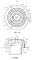
(第2実施形態)図7~図11において、この操作ダイヤルは、上記第1実施形態に比べて異なるクリック手段7Aを有する一例である。この説明では、以上の第1実施形態と同一又は類似する箇所には同じ符号を付し重複した記載を極力省きつつ、変更点を明らかにする。なお、図7と図8は第1実施形態の図1と図3に対応し、図10と図11は第1実施形態の図6と図7に対応している。また、図2は、第2実施形態でも同じ模式上面図となるため兼用している。
第2実施形態の操作ダイヤルは、主部材として、ダイヤル1に対応するダイヤル1Aと、ハウジング2に対応するハウジング2Aと、ローター8に対応するローター8Aとを備えている。また、ダイヤル1Aとハウジング2Aの間には、上記したフリクション機構3が設けられていると共に、第1実施形態のクリック手段7とは異なるクリック手段7Aが設けられている。このクリック手段7Aは、ダイヤル1Aに組付けられて凸5aと凹5bを交互に形成している節度面部4を内周面に有する円環部材5と、ハウジング2Aに組付けられて円環部材5の節度面部4である凸5aと凹5bに当接する当接部材を含む板ばね6とを有している。
ダイヤル1Aは、ダイヤル1に対し内周面11の開口側を一段径大に形成した径大内周面14を有している。径大内周面14には係合凹部14aが等間隔に複数設けられている。径大内周面14には円環部材5が装着される。円環部材5は、リング状をなし、外周面に設けられて係合凹部14aに係合する複数の突起5dと、内周面に設けられて上記節度面部4と同様な節度面部として機能するべく交互に連続して形成された凸5a及び凹5bとを有する。また、凹5bと凸5a、又は凸5aと凹5bのピッチ、つまり凸5aの頂点から凹5bの中心までの距離は周方向に沿って徐々に変化している。この例では、第1実施形態と同様、これらのピッチが図8(b)に示されるごとく円環部材5の外周面の基点5cから時計周りの方向に進むに従って徐々に大きくなるよう設定されている。そのため、このクリック手段7Aは、上記クリック手段7と同様、例えば、図8(b)の状態から、ダイヤル1Aが時計回りの方向に回転されると節度感が次第に強くなり、逆に、ダイヤル1Aが逆時計回りの方向に回転されると節度感が次第に弱くなる。
ハウジング2Aは円環部材5に対応して設けられた板ばね6を有している。板ばね6は、図9に示されるごとく中間に設けられた略U形の係合部6a(当接部材)と、係合部6aの両側に延設された係止片部6b,6bとからなる。ハウジング2Aは、外周面20のフランジ21よりも下方の一部が切り欠されて形成された開口20aを有する。また、フランジ21及び大径下周囲部22と中間周囲部23には、開口20aの中間部と対応して、下から上向きに空洞28が設けられている。空洞28は板ばね6に対応した大きさとなっている。更に、中間周囲部23には端面22a側に小窓23bが設けられ、小窓23bから空洞28に通じている。そして、板ばね6は、空洞28に押し入れられた状態で、係合部6aが小窓23bから外へ突出されると共に、両側の係止片部6bが空洞28の対応部に係止されている。
従って、この構造では、ダイヤル1Aがハウジング2Aに対しフリクション機構3の摩擦抵抗に抗して回転される過程において、クリック手段7Aが作用して、板ばね6の係合部6aが円環部材5の凸5aと凹5bに接触することに伴う感触が得られ良好なフィーリングを付与できることになる。なお、この構造において、上記形態のローター8に対応するローター8Aは、空洞28に対応して周囲部の一部が切り欠かれた形状となっている。また、クリック手段7Aに加えて第1実施形態のクリック手段7を設けて、2つのクリック手段7,7Aによる節度感が得られるようにしてもよい。
(変形例1)図12(a)の変形例1は、上記形態の当接部材であるローラー35を複数設けた構成を示している。すなわち、ハウジング2(2A)において、小径上周囲部24には凹所24bが等間隔で3つ設けられている。各凹所24bには、上記したローラー35が溝25(図4(a)参照)に嵌合する支軸37を介して回転自在に配設されている。
(変形例2)図12(b)の変形例2は、ローラー35の支軸38として、各形態の支軸37に比べて、溝25と嵌合する下軸部38aに対し上軸部38bが径小に形成されている。そして、支軸38は、ローラー35に設けられた装着穴35bに径小の上軸部38bを回転自在に嵌合している。要は、ローラー35を支軸38に対し回転自在に支持した構成である。
なお、以上で本発明の実施形態の説明を終えるが、本発明は、実施形態で説明した全ての構成を備えている必要はなく、また、細部は以上の各実施形態や変形例を参考にして更に変更したり展開可能である。その例として、各実施形態のOリング31を省略して簡素化したり、また、各凸4a,5aの高さや各凹4b,凹5bの深さを順に変化させて抵抗力を変化させるようにしてもよい。また、弾性体としては、Oリング以外でも他に角リングやXリングでもよい。更に、操作ダイヤルに代えてスライド式の操作摘みとしても差し支えない。第2実施形態の当接部材である板ばね6を各実施形態で採用したローラー35、又はそれに類似の構成に変更することも可能である。つまり、当接部材としては、板ばね以外でも他にコイルばね等のばね材でもよい。勿論、本発明のフリクション装置は、回転式操作部材、及びスライド式操作部材以外であっても色々な分野の部材に適用可能であり用途的な制約はない。
1・・・・・ダイヤル(第1部材:回転式操作部材)
1A・・・・ダイヤル(第1部材:回転式操作部材)
2・・・・・ハウジング(第2部材)
2A・・・・ハウジング(第2部材)
3・・・・・フリクション機構
4・・・・・節度面部(4aは凸、4bは凹、4cは基点)
5・・・・・円環部材(節度面部:5aは凹、5bは凸、5cは基点)
6・・・・・板ばね(6aは係合部(当接部材))
7・・・・・クリック手段
7A・・・・クリック手段
8・・・・・ローター
8A・・・・ローター
9・・・・・表示板(9a~9eは表示位置)
19・・・・マーク(10aは凹所)
24b・・・凹所
25・・・・溝
30・・・・Oリング(弾性体)
35・・・・ローラー(転動体)
37・・・・支軸
38・・・・支軸
1A・・・・ダイヤル(第1部材:回転式操作部材)
2・・・・・ハウジング(第2部材)
2A・・・・ハウジング(第2部材)
3・・・・・フリクション機構
4・・・・・節度面部(4aは凸、4bは凹、4cは基点)
5・・・・・円環部材(節度面部:5aは凹、5bは凸、5cは基点)
6・・・・・板ばね(6aは係合部(当接部材))
7・・・・・クリック手段
7A・・・・クリック手段
8・・・・・ローター
8A・・・・ローター
9・・・・・表示板(9a~9eは表示位置)
19・・・・マーク(10aは凹所)
24b・・・凹所
25・・・・溝
30・・・・Oリング(弾性体)
35・・・・ローラー(転動体)
37・・・・支軸
38・・・・支軸
Claims (10)
- 第1部材と、第2部材と、摩擦力に抗して前記両部材を相対的に移動可能とするべく前記両部材の間に配置されたフリクション機構とを有するフリクション装置であって、
前記フリクション機構が、前記摩擦力を発生させるべく前記両部材の間に介在するように前記第1部材に取り付けられた弾性体と、前記第2部材に回転自在に支持されて前記弾性体上を転動する転動体とを有していることを特徴とするフリクション装置。 - 前記弾性体がOリングを含むと共に、前記転動体が概略円柱状ないしは球状のローラーを含むことを特徴とする請求項1に記載のフリクション装置。
- 前記第1部材に設けられて凹と凸を交互に形成している節度面部と、前記第2部材に設けられて前記節度面部に当接するべく弾発支持された当接部材とを備えるクリック手段を更に有していることを特徴とする請求項1又は2に記載のフリクション装置。
- 前記転動体が前記当接部材を兼ねていることを特徴とする請求項3に記載のフリクション装置。
- 前記第2部材は、前記転動体に対する前記弾性体の移動方向に角度をなすように延在する溝を有し、
前記転動体は、前記溝に該溝の延在方向に摺動可能に受容された支軸を介して前記第2部材に回転自在に支持されたことを特徴とする請求項4に記載のフリクション装置。 - 前記当接部材が板ばねの一部にて形成されていることを特徴とする請求項3に記載のフリクション装置。
- 前記凹と前記凸とのピッチが不均一であることを特徴とする請求項3から6の何れかに記載のフリクション装置。
- 前記凹の深さと前記凸の高さの少なくとも一方が不均一であることを特徴とする請求項3から7の何れかに記載のフリクション装置。
- 前記両部材の一方が他方に対して回転可能な回転式操作部材であることを特徴とする請求項1から8の何れかに記載のフリクション装置。
- 前記両部材の一方が他方に対してスライド移動可能なスライド式操作部材であることを特徴とする請求項1から8の何れかに記載のフリクション装置。
Applications Claiming Priority (2)
| Application Number | Priority Date | Filing Date | Title |
|---|---|---|---|
| JP2017-026773 | 2017-02-16 | ||
| JP2017026773A JP2018133231A (ja) | 2017-02-16 | 2017-02-16 | フリクション機構及びそれを採用した操作部材 |
Publications (1)
| Publication Number | Publication Date |
|---|---|
| WO2018151272A1 true WO2018151272A1 (ja) | 2018-08-23 |
Family
ID=63169448
Family Applications (1)
| Application Number | Title | Priority Date | Filing Date |
|---|---|---|---|
| PCT/JP2018/005569 Ceased WO2018151272A1 (ja) | 2017-02-16 | 2018-02-16 | フリクション装置 |
Country Status (2)
| Country | Link |
|---|---|
| JP (1) | JP2018133231A (ja) |
| WO (1) | WO2018151272A1 (ja) |
Citations (12)
| Publication number | Priority date | Publication date | Assignee | Title |
|---|---|---|---|---|
| JPS54101375U (ja) * | 1977-12-27 | 1979-07-17 | ||
| JPS5983190U (ja) * | 1982-11-26 | 1984-06-05 | 株式会社シマノ | 変速操作装置 |
| DE3540492C1 (en) * | 1985-11-15 | 1987-04-02 | Kostal Leopold Gmbh & Co Kg | Latching device for electrical switches |
| JPH04106825A (ja) * | 1990-08-24 | 1992-04-08 | Mitsubishi Electric Corp | 気密構造の数値設定機構 |
| JPH0674262A (ja) * | 1992-08-28 | 1994-03-15 | Nippon Plast Co Ltd | 回転ダンパー |
| JPH07296678A (ja) * | 1994-04-26 | 1995-11-10 | Sakae Tsushin Kogyo Kk | 多極切換スイッチ |
| DE19707170A1 (de) * | 1997-02-22 | 1998-08-27 | Valeo Klimasysteme Gmbh | Stufenschalter |
| JP2008213563A (ja) * | 2007-03-01 | 2008-09-18 | Suzuki Motor Corp | ステアリングシステム |
| JP2008299667A (ja) * | 2007-05-31 | 2008-12-11 | Icom Inc | 回転ツマミのトルク調整構造及び弾性部材 |
| JP2013118159A (ja) * | 2011-11-04 | 2013-06-13 | Tokyo Cosmos Electric Co Ltd | 電気部品のクリック機構 |
| JP2013254621A (ja) * | 2012-06-06 | 2013-12-19 | Tokai Rika Co Ltd | スイッチ装置 |
| WO2016124356A1 (de) * | 2015-02-05 | 2016-08-11 | Zf Friedrichshafen Ag | Vorrichtung und verfahren zum einstellen einer drehbewegung oder schwenkbewegung eines bedienelements für ein fahrzeug |
-
2017
- 2017-02-16 JP JP2017026773A patent/JP2018133231A/ja active Pending
-
2018
- 2018-02-16 WO PCT/JP2018/005569 patent/WO2018151272A1/ja not_active Ceased
Patent Citations (12)
| Publication number | Priority date | Publication date | Assignee | Title |
|---|---|---|---|---|
| JPS54101375U (ja) * | 1977-12-27 | 1979-07-17 | ||
| JPS5983190U (ja) * | 1982-11-26 | 1984-06-05 | 株式会社シマノ | 変速操作装置 |
| DE3540492C1 (en) * | 1985-11-15 | 1987-04-02 | Kostal Leopold Gmbh & Co Kg | Latching device for electrical switches |
| JPH04106825A (ja) * | 1990-08-24 | 1992-04-08 | Mitsubishi Electric Corp | 気密構造の数値設定機構 |
| JPH0674262A (ja) * | 1992-08-28 | 1994-03-15 | Nippon Plast Co Ltd | 回転ダンパー |
| JPH07296678A (ja) * | 1994-04-26 | 1995-11-10 | Sakae Tsushin Kogyo Kk | 多極切換スイッチ |
| DE19707170A1 (de) * | 1997-02-22 | 1998-08-27 | Valeo Klimasysteme Gmbh | Stufenschalter |
| JP2008213563A (ja) * | 2007-03-01 | 2008-09-18 | Suzuki Motor Corp | ステアリングシステム |
| JP2008299667A (ja) * | 2007-05-31 | 2008-12-11 | Icom Inc | 回転ツマミのトルク調整構造及び弾性部材 |
| JP2013118159A (ja) * | 2011-11-04 | 2013-06-13 | Tokyo Cosmos Electric Co Ltd | 電気部品のクリック機構 |
| JP2013254621A (ja) * | 2012-06-06 | 2013-12-19 | Tokai Rika Co Ltd | スイッチ装置 |
| WO2016124356A1 (de) * | 2015-02-05 | 2016-08-11 | Zf Friedrichshafen Ag | Vorrichtung und verfahren zum einstellen einer drehbewegung oder schwenkbewegung eines bedienelements für ein fahrzeug |
Also Published As
| Publication number | Publication date |
|---|---|
| JP2018133231A (ja) | 2018-08-23 |
Similar Documents
| Publication | Publication Date | Title |
|---|---|---|
| US7533474B2 (en) | Caliper gauge | |
| JP5982023B2 (ja) | 回転/押しボタン制御装置 | |
| US10133296B2 (en) | Multidirectional operating device | |
| WO2018151272A1 (ja) | フリクション装置 | |
| CN204808051U (zh) | 一种多功能控制元件及具有该控制元件的车辆 | |
| JP4430683B2 (ja) | 電子機器の操作装置 | |
| JP2011210507A (ja) | 回転型電気部品 | |
| JP4590432B2 (ja) | 操作装置及び操作システム | |
| JP2011192477A (ja) | 回転つまみのトルク可変機構 | |
| JP2011209876A (ja) | ダイヤル装置及び電子機器 | |
| JP2009054459A (ja) | 節度装置 | |
| JP2009301097A (ja) | 節度装置 | |
| JP2006003737A (ja) | ディスプレイ支持装置 | |
| JP2002227825A (ja) | 携帯用機器のヒンジ装置 | |
| CN210299494U (zh) | 一种电子烟的功率调节装置及电子烟 | |
| WO2007136029A1 (ja) | 回転型電気部品 | |
| JP4353507B2 (ja) | 回転操作つまみのトルク可変機構 | |
| JP4388800B2 (ja) | 回転ツマミの制動力調節機構 | |
| JP2000298527A (ja) | 回転つまみの負荷トルク設定機構 | |
| JP2009199156A (ja) | 節度装置 | |
| CN220019870U (zh) | 一种激光测距结构 | |
| JP2004356441A (ja) | 部材回動構造および電子機器 | |
| JP6409829B2 (ja) | 操作装置 | |
| JP5862477B2 (ja) | トルク可変装置、及び電子機器 | |
| JP6471053B2 (ja) | 回転型電気部品 |
Legal Events
| Date | Code | Title | Description |
|---|---|---|---|
| 121 | Ep: the epo has been informed by wipo that ep was designated in this application |
Ref document number: 18754297 Country of ref document: EP Kind code of ref document: A1 |
|
| NENP | Non-entry into the national phase |
Ref country code: DE |
|
| 122 | Ep: pct application non-entry in european phase |
Ref document number: 18754297 Country of ref document: EP Kind code of ref document: A1 |