WO2018151259A1 - 蒸気タービンプラント - Google Patents
蒸気タービンプラント Download PDFInfo
- Publication number
- WO2018151259A1 WO2018151259A1 PCT/JP2018/005510 JP2018005510W WO2018151259A1 WO 2018151259 A1 WO2018151259 A1 WO 2018151259A1 JP 2018005510 W JP2018005510 W JP 2018005510W WO 2018151259 A1 WO2018151259 A1 WO 2018151259A1
- Authority
- WO
- WIPO (PCT)
- Prior art keywords
- steam
- pressure
- low
- ground
- steam turbine
- Prior art date
- Legal status (The legal status is an assumption and is not a legal conclusion. Google has not performed a legal analysis and makes no representation as to the accuracy of the status listed.)
- Ceased
Links
Images
Classifications
-
- F—MECHANICAL ENGINEERING; LIGHTING; HEATING; WEAPONS; BLASTING
- F16—ENGINEERING ELEMENTS AND UNITS; GENERAL MEASURES FOR PRODUCING AND MAINTAINING EFFECTIVE FUNCTIONING OF MACHINES OR INSTALLATIONS; THERMAL INSULATION IN GENERAL
- F16J—PISTONS; CYLINDERS; SEALINGS
- F16J15/00—Sealings
- F16J15/44—Free-space packings
-
- F—MECHANICAL ENGINEERING; LIGHTING; HEATING; WEAPONS; BLASTING
- F01—MACHINES OR ENGINES IN GENERAL; ENGINE PLANTS IN GENERAL; STEAM ENGINES
- F01K—STEAM ENGINE PLANTS; STEAM ACCUMULATORS; ENGINE PLANTS NOT OTHERWISE PROVIDED FOR; ENGINES USING SPECIAL WORKING FLUIDS OR CYCLES
- F01K7/00—Steam engine plants characterised by the use of specific types of engine; Plants or engines characterised by their use of special steam systems, cycles or processes; Control means specially adapted for such systems, cycles or processes; Use of withdrawn or exhaust steam for feed-water heating
- F01K7/16—Steam engine plants characterised by the use of specific types of engine; Plants or engines characterised by their use of special steam systems, cycles or processes; Control means specially adapted for such systems, cycles or processes; Use of withdrawn or exhaust steam for feed-water heating the engines being only of turbine type
- F01K7/18—Steam engine plants characterised by the use of specific types of engine; Plants or engines characterised by their use of special steam systems, cycles or processes; Control means specially adapted for such systems, cycles or processes; Use of withdrawn or exhaust steam for feed-water heating the engines being only of turbine type the turbine being of multiple-inlet-pressure type
- F01K7/20—Control means specially adapted therefor
-
- F—MECHANICAL ENGINEERING; LIGHTING; HEATING; WEAPONS; BLASTING
- F01—MACHINES OR ENGINES IN GENERAL; ENGINE PLANTS IN GENERAL; STEAM ENGINES
- F01D—NON-POSITIVE DISPLACEMENT MACHINES OR ENGINES, e.g. STEAM TURBINES
- F01D11/00—Preventing or minimising internal leakage of working-fluid, e.g. between stages
- F01D11/02—Preventing or minimising internal leakage of working-fluid, e.g. between stages by non-contact sealings, e.g. of labyrinth type
- F01D11/04—Preventing or minimising internal leakage of working-fluid, e.g. between stages by non-contact sealings, e.g. of labyrinth type using sealing fluid, e.g. steam
-
- F—MECHANICAL ENGINEERING; LIGHTING; HEATING; WEAPONS; BLASTING
- F01—MACHINES OR ENGINES IN GENERAL; ENGINE PLANTS IN GENERAL; STEAM ENGINES
- F01D—NON-POSITIVE DISPLACEMENT MACHINES OR ENGINES, e.g. STEAM TURBINES
- F01D25/00—Component parts, details, or accessories, not provided for in, or of interest apart from, other groups
- F01D25/24—Casings; Casing parts, e.g. diaphragms, casing fastenings
-
- F—MECHANICAL ENGINEERING; LIGHTING; HEATING; WEAPONS; BLASTING
- F01—MACHINES OR ENGINES IN GENERAL; ENGINE PLANTS IN GENERAL; STEAM ENGINES
- F01K—STEAM ENGINE PLANTS; STEAM ACCUMULATORS; ENGINE PLANTS NOT OTHERWISE PROVIDED FOR; ENGINES USING SPECIAL WORKING FLUIDS OR CYCLES
- F01K13/00—General layout or general methods of operation of complete plants
- F01K13/02—Controlling, e.g. stopping or starting
-
- F—MECHANICAL ENGINEERING; LIGHTING; HEATING; WEAPONS; BLASTING
- F01—MACHINES OR ENGINES IN GENERAL; ENGINE PLANTS IN GENERAL; STEAM ENGINES
- F01K—STEAM ENGINE PLANTS; STEAM ACCUMULATORS; ENGINE PLANTS NOT OTHERWISE PROVIDED FOR; ENGINES USING SPECIAL WORKING FLUIDS OR CYCLES
- F01K7/00—Steam engine plants characterised by the use of specific types of engine; Plants or engines characterised by their use of special steam systems, cycles or processes; Control means specially adapted for such systems, cycles or processes; Use of withdrawn or exhaust steam for feed-water heating
- F01K7/16—Steam engine plants characterised by the use of specific types of engine; Plants or engines characterised by their use of special steam systems, cycles or processes; Control means specially adapted for such systems, cycles or processes; Use of withdrawn or exhaust steam for feed-water heating the engines being only of turbine type
- F01K7/18—Steam engine plants characterised by the use of specific types of engine; Plants or engines characterised by their use of special steam systems, cycles or processes; Control means specially adapted for such systems, cycles or processes; Use of withdrawn or exhaust steam for feed-water heating the engines being only of turbine type the turbine being of multiple-inlet-pressure type
-
- F—MECHANICAL ENGINEERING; LIGHTING; HEATING; WEAPONS; BLASTING
- F16—ENGINEERING ELEMENTS AND UNITS; GENERAL MEASURES FOR PRODUCING AND MAINTAINING EFFECTIVE FUNCTIONING OF MACHINES OR INSTALLATIONS; THERMAL INSULATION IN GENERAL
- F16J—PISTONS; CYLINDERS; SEALINGS
- F16J15/00—Sealings
- F16J15/44—Free-space packings
- F16J15/447—Labyrinth packings
- F16J15/4472—Labyrinth packings with axial path
Definitions
- the present invention relates to a steam turbine plant including a plurality of steam turbines.
- the end of the rotating shaft of the rotor protrudes outside through an opening formed in the casing.
- the steam is passed through the gap between the opening of the casing and the rotating shaft, thereby ensuring the sealing performance at the end of the rotating shaft.
- the inside of the turbine casing has a pressure higher than the atmospheric pressure. For this reason, at the end of the rotary shaft of the high-pressure side steam turbine, steam flows out from the inside of the turbine casing to the outside through the gap between the opening of the casing and the rotary shaft (hereinafter, this steam is appropriately referred to as ground steam).
- the sealing performance at the end of the rotating shaft is secured.
- the inside of the turbine casing has a pressure lower than the atmospheric pressure.
- air easily enters the inside of the casing from the outside through the gap between the opening of the casing and the rotating shaft. Therefore, the ground steam that has passed through the gap between the opening of the casing of the high-pressure side steam turbine and the end of the rotating shaft is supplied to the gap between the opening of the casing of the low-pressure side steam turbine and the rotating shaft. The seal at the end of the shaft is secured.
- the flow rate of the ground steam supplied from the high-pressure side steam turbine to the low-pressure side steam turbine varies depending on the operating state of each steam turbine. That is, when the steam turbine plant is started, the flow rate of the ground steam supplied from the high pressure side steam turbine to the low pressure side steam turbine is small. Further, when the steam turbine plant is in the rated operation state, the flow rate of the ground steam supplied from the high pressure side steam turbine to the low pressure side steam turbine increases.
- Patent Document 1 when the flow rate of ground steam supplied from the high-pressure side steam turbine to the low-pressure side steam turbine exceeds the amount of steam required by the low-pressure side steam turbine, surplus ground steam is A configuration is disclosed in which a condensate is sent to a condenser provided in a steam turbine plant. However, if the excess ground steam is heat-exchanged by the condenser, the heat energy of the ground steam is discarded. Therefore, Patent Document 1 discloses a configuration in which surplus ground steam is supplied to a ground steam condenser that exchanges heat with water discharged from the condenser. According to this configuration, by supplying surplus steam to the ground condenser, the efficiency of thermal energy can be increased as compared with the case where surplus ground steam is fed into the condenser.
- an object of the present invention is to provide a steam turbine plant capable of effectively using ground steam and improving plant efficiency.
- a steam turbine plant as one aspect according to the invention for achieving the above object includes a high-pressure casing into which steam flows and an opening formed in the high-pressure casing at both ends thereof.
- a high-pressure side steam turbine having a high-pressure turbine rotor rotating outward by the steam flowing into the high-pressure casing, a low-pressure casing into which the steam exhausted from the high-pressure side steam turbine flows, and the low-pressure
- a low-pressure side steam turbine having a low-pressure turbine rotor that is provided in the casing and whose both ends face outward from an opening formed in the low-pressure casing and rotates by the steam flowing into the low-pressure casing; Is provided.
- the high-pressure-side steam turbine has a high-pressure gland part that seals the gap by supplying the steam as gland steam to the gap between the opening of the high-pressure casing and the end of the high-pressure turbine rotor.
- the low-pressure side steam turbine has a low-pressure gland part that seals the gap by supplying the ground steam to a gap between the opening of the low-pressure casing and the end of the low-pressure turbine rotor.
- the steam turbine plant further includes a ground regulator line that guides the ground steam from the high-pressure ground part to the low-pressure ground part, and a branch from the ground regulator line, and a part of the ground steam is part of the ground pressure in the low-pressure casing.
- a rotor drive steam supply line that supplies the steam flow path for rotating the low-pressure turbine rotor.
- a part of the ground steam fed from the high pressure gland part of the high pressure side steam turbine to the low pressure gland part of the low pressure side steam turbine is used to rotate the low pressure turbine rotor in the low pressure casing of the low pressure side steam turbine.
- a part of ground steam can be used as energy for rotating the low-pressure turbine rotor.
- the rotor drive steam supply line may supply a part of the ground steam to a portion of the low pressure casing where the pressure is lower than the ground steam supplied from the ground regulator line.
- the ground steam can be efficiently supplied into the low-pressure casing through the rotor-driven steam supply line, and the flow speed of the ground steam sent into the low-pressure casing is also increased.
- the low-pressure turbine rotor can be rotated more efficiently.
- a flow rate adjusting valve for adjusting the flow rate of the ground steam flowing through the rotor drive steam supply line may be provided.
- the amount of ground steam supplied into the low pressure casing of the low pressure steam turbine can be adjusted according to the amount required in the low pressure side steam turbine.
- a correlation value detector for detecting a steam flow rate correlation value correlated with the flow rate of the ground steam flowing through the ground regulator line may be provided.
- the flow rate control valve may be opened when the steam flow rate correlation value detected by the correlation value detector is equal to or greater than a predetermined value.
- the flow rate of the ground steam flowing through the ground regulator line varies according to the operating state of the high-pressure side steam turbine and the low-pressure side steam turbine. For example, when the steam turbine plant is started, the flow rate of the ground steam flowing through the ground regulator line is small. After the start of the steam turbine plant, the flow rate of the ground steam flowing through the ground regulator line increases as the operating speed of the high-pressure side steam turbine and the low-pressure side steam turbine increases. In such a state, the flow rate of the ground steam sent out from the high pressure side steam turbine may exceed the flow rate of the ground steam required in the low pressure side steam turbine, and surplus ground steam may be generated. When surplus ground steam is generated in this way, the drive energy for rotating the low-pressure turbine rotor of the low-pressure side steam turbine is increased by increasing the flow rate of the ground steam flowing through the rotor-driven steam supply line. Can be used effectively.
- the low-pressure side steam turbine is fixed to the inner peripheral side of the low-pressure casing, and is provided with a plurality of stages of stationary blade rows that are spaced apart from each other in the axial direction of the low-pressure turbine rotor, and the low-pressure turbine rotor And a plurality of stages of moving blade rows that are formed on the outer peripheral portion and are spaced from each other in the axial direction with respect to the stationary blade rows of each stage.
- the rotor-driven steam supply line is upstream of the second and subsequent stages of the stationary blade rows excluding the most upstream side of the steam flow direction in the low-pressure casing among the plurality of stages of stationary blade rows. Then, it may be connected to the low pressure casing on the downstream side of the moving blade row arranged adjacent to the upstream side of the stationary blade row.
- the ground steam supplied into the low-pressure casing through the rotor drive steam supply line is sent upstream of the stationary blade row and downstream of the moving blade row, so that the fed ground steam is supplied. Can inhibit the rotation of the rotor blade row.
- the low-pressure side steam turbine is fixed to the inner peripheral side of the low-pressure casing, and is provided with a plurality of stages of stationary blade rows that are spaced apart from each other in the axial direction of the low-pressure turbine rotor, and the low-pressure turbine rotor And a plurality of stages of moving blade rows that are formed on the outer peripheral portion and are spaced from each other in the axial direction with respect to the stationary blade rows of each stage.
- the rotor-driven steam supply line may be connected to the low-pressure casing so as to face at least one stage in the radial direction of the plurality of blade rows.
- the ground steam supplied into the low-pressure casing through the rotor-driven steam supply line is sent from the position facing the radially outer side of the rotor blade row, so that the sent ground steam rotates the rotor blade row. Can be suppressed. Moreover, the sealing performance of the clearance gap between the outer peripheral part of a low-pressure turbine rotor and the casing inner peripheral surface of the outer peripheral side can be improved by the ground steam sent from the rotor driving steam supply line.
- FIG. 1 is a system diagram of a steam turbine plant in a first embodiment according to the present invention. It is sectional drawing of the high pressure side steam turbine which comprises the steam turbine plant in 1st embodiment which concerns on this invention. It is sectional drawing of the low pressure side steam turbine which comprises the steam turbine plant in 1st embodiment which concerns on this invention. It is a diagram which shows the supply form of a ground steam when starting the steam turbine plant in 1st embodiment which concerns on this invention. It is sectional drawing of the low pressure side steam turbine which comprises the steam turbine plant in 2nd embodiment which concerns on this invention. It is a systematic diagram which shows the modification of the steam turbine plant in 1st, 2nd embodiment which concerns on this invention.
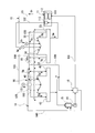
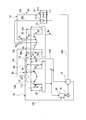
- FIG. 1 is a schematic diagram showing a configuration of a steam turbine plant according to a first embodiment of the present invention.
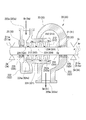
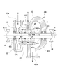
- FIG. 2 is a cross-sectional view of the high-pressure side steam turbine constituting the steam turbine plant according to the first embodiment of the present invention.
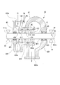
- FIG. 3 is a cross-sectional view of the low-pressure side steam turbine constituting the steam turbine plant according to the first embodiment of the present invention.
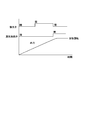
- FIG. 4 is a diagram showing a supply form of ground steam when starting the steam turbine plant according to the first embodiment of the present invention. As shown in FIG.
- the steam turbine plant 10 of this embodiment includes a boiler 11, a high-pressure steam turbine (high-pressure side steam turbine) 20, an intermediate-pressure steam turbine (high-pressure side steam turbine) 30, and a low-pressure steam turbine ( Low pressure side steam turbine) 40, condenser 15, condensate pump 16, and steam seal mechanism 50 are mainly provided.
- the boiler 11 generates steam.
- the heat source of the boiler 11 is not questioned at all.
- the heat of exhaust gas from a gas turbine (not shown) may be used.
- the boiler 11 includes an evaporator 111, a superheater 112, and a reheater 113.
- the high-pressure steam turbine 20 includes a high-pressure casing 22 into which steam flows from a high-pressure steam line 101, a high-pressure turbine rotor 21 provided in the high-pressure casing 22, and a high-pressure gland portion 23. Prepare.
- the high-pressure casing 22 is provided on the cylindrical casing 221, the inlet scroll 222 provided on the first side of the casing 221 in the axis Ar direction, and the second side of the casing 221 in the axis Ar direction. And an exit scroll 223.
- the high-pressure steam Sh generated in the boiler 11 flows into the vehicle compartment 221 from the steam suction port 222 a formed in the inlet scroll 222 through the high-pressure steam line 101.
- the inflowing high-pressure steam Sh flows in the passenger compartment 221 from the entrance scroll 222 side to the exit scroll 223 side, and is discharged to the outside from a steam discharge port 223a formed in the exit scroll 223.
- a plurality of stages of stationary blade rows 224 provided at intervals in the axis Ar direction are provided on the inner peripheral side of the casing 221.
- Each stationary blade row 224 includes a plurality of stationary blades 224a at intervals in the circumferential direction Dr around the axis Ar.
- the high-pressure turbine rotor 21 includes a rotating shaft 211 that extends along the axis Ar direction, and a moving blade row 212 that is integrally provided on the radially outer side of the rotating shaft 211.
- the rotating shaft 211 is provided such that both end portions 211 a and 211 a thereof face the outside of the high-pressure casing 22 from openings 225 and 225 formed on both sides of the high-pressure casing 22 in the axis Ar direction. Both ends 211a and 211a of the rotating shaft 211 are supported on the outside of the high-pressure casing 22 by bearings 24 so as to be rotatable around the axis Ar.
- the moving blade row 212 is formed integrally with the outer peripheral portion of the rotating shaft 211.
- the moving blade rows 212 are provided in a plurality of stages at intervals in the direction of the axis Ar of the rotating shaft 211.
- the moving blade row 212 of each stage is arranged at an interval in the axis Ar direction with respect to each stage of the stationary blade row 224 provided in a plurality of stages.
- Each moving blade row 212 includes a plurality of moving blades 212a at intervals in the circumferential direction Dr around the axis Ar.
- the swirl flow of the high-pressure steam Sh generated in the stationary blade row 224 of each stage hits the moving blade 212 a of each rotor blade row 212, so that the rotor blade row 212 and the rotating shaft 211 of each stage. Rotate integrally around the axis Ar.
- the high-pressure gland part 23 is configured such that a part of the high-pressure steam Sh in the passenger compartment 221 flows as the ground steam Sg into the gap between the opening 225 of the high-pressure casing 22 and the end 211a of the high-pressure turbine rotor 21. Seal.
- the ground vapor Sg that has flowed into the high-pressure ground unit 23 is discharged to the ground regulator line 110 described later. Further, a part of the ground vapor Sg flowing into the high-voltage ground part 23 is sucked out to the ground capacitor line 130.
- the high-pressure steam Sh sent from the boiler 11 through the high-pressure steam line 101 rotates the high-pressure turbine rotor 21 while decompressing and expanding in the passenger compartment 221.
- the high pressure steam turbine 20 outputs the rotational force of the rotating shaft 211 of the high pressure turbine rotor 21 to the outside.
- the intermediate pressure steam turbine 30 is fed with the intermediate pressure steam line 102 through which the high pressure steam Sh discharged from the high pressure steam turbine 20 is decompressed and expanded. As shown in FIG. 2, the intermediate pressure steam line 102 passes through a reheater 113 provided in the boiler 11, whereby the intermediate pressure steam Sm discharged from the high pressure steam turbine 20 is reheated. Is heated.
- the intermediate pressure steam turbine 30 includes an intermediate pressure casing 32 into which steam flows from the intermediate pressure steam line 102, an intermediate pressure turbine rotor 31 provided in the intermediate pressure casing 32, and an intermediate pressure ground portion 33. .
- the intermediate pressure casing 32 is provided on the cylindrical casing 321, the inlet scroll 322 provided on the first side of the casing 321 in the axis Ar direction, and the second side of the casing 321 in the axis Ar direction. And an exit scroll 323.
- the intermediate pressure steam Sm discharged from the high pressure steam turbine 20 flows into the vehicle interior 321 through the intermediate pressure steam line 102 from a steam suction port 322 a formed in the inlet scroll 322.
- the inflowing intermediate pressure steam Sm flows in the passenger compartment 321 from the inlet scroll 322 side to the outlet scroll 323 side, and is discharged to the outside from a steam discharge port 323 a formed in the outlet scroll 323.
- a plurality of stages of stationary blade rows 324 are provided on the inner peripheral side of the passenger compartment 321 so as to be spaced apart from each other in the direction of the axis Ar.
- Each stationary blade row 324 includes a plurality of stationary blades 324a at intervals in the circumferential direction Dr around the axis Ar.
- the intermediate pressure turbine rotor 31 includes a rotating shaft 311 extending along the axis Ar direction, and a moving blade row 312 provided integrally on the radially outer side of the rotating shaft 311.
- the rotating shaft 311 is provided so that both end portions 311a and 311a thereof face outward from openings 325 and 325 formed on both sides of the intermediate pressure casing 32 in the axis Ar direction. Both ends 311a and 311a of the rotating shaft 311 are supported by the bearings 34 so as to be rotatable around the axis Ar on the outside of the intermediate pressure casing 32.
- the moving blade row 312 is integrally formed on the outer peripheral portion of the rotating shaft 311.
- the moving blade rows 312 are provided in a plurality of stages at intervals in the axis Ar direction of the rotating shaft 311.
- the moving blade row 312 of each stage is arranged at intervals in the axis Ar direction with respect to each stage of the stationary blade row 324 provided in a plurality of stages.
- Each moving blade row 312 is provided with a plurality of moving blades 312a at intervals in the circumferential direction Dr around the axis Ar.
- the intermediate pressure turbine rotor 31 rotates with the moving blade row 312 of each stage by the swirling flow of the intermediate pressure steam Sm generated by the stationary blade row 324 of each stage hitting the moving blade 312a of each moving blade row 312.
- the shaft 311 rotates integrally around the axis Ar.
- the intermediate pressure gland portion 33 is configured such that a part of the intermediate pressure steam Sm in the passenger compartment 321 flows into the gap between the opening 325 of the intermediate pressure casing 32 and the end 311a of the intermediate pressure turbine rotor 31 as the ground steam Sg. , Seal this gap.
- the ground vapor Sg that has flowed into the intermediate pressure ground portion 33 is discharged to the ground regulator line 110 described later. Further, a part of the ground vapor Sg flowing into the intermediate pressure ground part 33 is sucked into the ground capacitor line 130.
- the intermediate pressure steam turbine 30 is fed with the intermediate pressure steam Sm via the intermediate pressure steam line 102.
- the intermediate pressure steam Sm rotates and drives the intermediate pressure turbine rotor 31 while decompressing and expanding in the vehicle interior 321 of the intermediate pressure steam turbine 30.
- the intermediate pressure steam turbine 30 outputs the rotational force of the rotation shaft 311 of the intermediate pressure turbine rotor 31 to the outside.
- the low-pressure steam Sl discharged from the medium-pressure steam turbine 30 after the medium-pressure steam Sm is decompressed and expanded is fed through the low-pressure steam line 103.
- the low pressure steam turbine 40 includes a low pressure casing 42 into which steam flows from the low pressure steam line 103, a low pressure turbine rotor 41 provided in the low pressure casing 42, and a low pressure ground portion 43.
- the low-pressure casing 42 is provided on the cylindrical casing 421, the inlet scroll 422 provided on the first side of the casing 421 in the axis Ar direction, and the second side of the casing 421 in the axis Ar direction. And an exit scroll 423.
- the low-pressure steam Sl discharged from the high-pressure steam turbine 20 flows into the vehicle compartment 421 from the steam inlet 422 a formed in the inlet scroll 422 through the low-pressure steam line 103.
- the low-pressure steam Sl that has flowed flows in the passenger compartment 421 from the inlet scroll 422 side toward the outlet scroll 423 side, and is discharged to the outside from a steam discharge port 423a formed in the outlet scroll 423.
- a plurality of stages of stationary blade rows 424 provided at intervals in the axis Ar direction are provided on the inner peripheral side of the passenger compartment 421.
- Each stationary blade row 424 includes a plurality of stationary blades 424a at intervals in the circumferential direction Dr around the axis Ar.
- the low-pressure turbine rotor 41 includes a rotating shaft 411 extending along the axis Ar direction, and a moving blade row 412 provided integrally on the radially outer side of the rotating shaft 411.
- the rotating shaft 411 is provided such that both end portions 411a and 411a thereof face outward from openings 425 and 425 formed on both sides of the low-pressure casing 42 in the axis Ar direction. Both ends 411a and 411a of the rotating shaft 411 are supported on the outside of the low-pressure casing 42 by bearings 44 so as to be rotatable around the axis Ar.
- the moving blade row 412 is formed integrally with the outer peripheral portion of the rotating shaft 411.
- the moving blade rows 412 are provided in a plurality of stages at intervals in the direction of the axis Ar of the rotating shaft 411.
- the moving blade row 412 of each stage is arranged at an interval in the axis Ar direction with respect to each stage of the stationary blade row 424 provided in a plurality of stages.
- Each blade array 412 is provided with a plurality of blades 412a at intervals in the circumferential direction Dr around the axis Ar.
- the rotating blade row 412 of each stage and the rotating shaft 411 are brought into contact with the rotating blade 412 a of each moving blade row 412 by the swirling flow of the low-pressure steam Sl generated in the stationary blade row 424 of each stage. Rotate integrally around the axis Ar.
- a main steam flow path (flow path) 45 in which a low-pressure steam Sl flows in an annular space between the inner peripheral surface of the passenger compartment 421 and the outer peripheral surface of the rotary shaft 411 of the low-pressure turbine rotor 41. It is said that.
- the low-pressure gland portion 43 seals the gap by supplying the ground steam Sg flowing through the gland regulator line 110 to the gap between the opening 425 of the low-pressure casing 42 and the end 411a of the low-pressure turbine rotor 41. .
- the ground vapor Sg flowing into the low-pressure ground part 43 is discharged to the ground capacitor line 130 described later.
- the low-pressure steam Sl is fed into the low-pressure steam turbine 40 through the low-pressure steam line 103.
- the low-pressure steam Sl rotates the low-pressure turbine rotor 41 while decompressing and expanding in the passenger compartment 421 of the low-pressure steam turbine 40.
- the low pressure steam turbine 40 outputs the rotational force of the rotating shaft 411 of the low pressure turbine rotor 41 to the outside.
- the condenser 15 is connected to a low pressure casing 42 of the low pressure steam turbine 40.
- the steam discharged from the low-pressure steam turbine 40 flows into the condenser 15 and returns the steam to water by heat exchange.
- the condenser pump 16 is provided in a water supply line 105 that connects the condenser 15 and the boiler 11, and sends the water in the condenser 15 to the boiler 11.
- the steam seal mechanism 50 includes a ground regulator line 110, a rotor drive steam supply line 120, and a ground capacitor line 130.
- the ground regulator line 110 guides the ground vapor Sg from the high-pressure ground part 23 and the intermediate-pressure ground part 33 to the low-pressure ground part 43.
- the ground condenser line 130 collects ground steam Sg discharged from the high pressure ground section 23 of the high pressure steam turbine 20, the medium pressure ground section 33 of the intermediate pressure steam turbine 30, and the low pressure ground section 43 of the low pressure steam turbine 40 to collect the ground condenser.
- the ground condenser 18 exchanges heat between the water flowing through the water supply line 105 and the ground steam Sg fed through the ground condenser line 130. Thereby, the water from the condenser 15 is heated, and the ground steam Sg is cooled.
- the ground steam Sg cooled by the ground condenser 18 is sent to the condenser 15 through the connection pipe 106 and returned to the water.
- the rotor drive steam supply line 120 is a line branched from the ground regulator line 110.
- the rotor-driven steam supply line 120 is configured so that a part of the ground steam Sg fed from the high-pressure ground portion 23 of the high-pressure steam turbine 20 and the intermediate-pressure ground portion 33 of the intermediate-pressure steam turbine 30 through the ground regulator line 110 is transferred into the low-pressure casing 42. Is supplied to the main steam flow path 45 for rotating the low-pressure turbine rotor 41.
- the rotor drive steam supply line 120 is connected to a portion in the low pressure casing 42 where the pressure P1 is lower than the pressure P0 of the ground steam Sg supplied from the ground regulator line 110. .
- the rotor-driven steam supply line 120 includes the second and subsequent stages excluding the most upstream side in the steam flow direction in the main steam channel 45 of the low-pressure casing 42 in the plurality of stages of stationary blade rows 424.
- the low pressure casing 42 is connected to the upstream side of the stationary blade row 424 and the downstream side of the moving blade row 412 disposed upstream of the stationary blade row 424.
- the ground steam Sg fed through the rotor drive steam supply line 120 joins with the steam in the passenger compartment 421 flowing through the main steam flow path 45, and rotates the low-pressure turbine rotor 41.
- the steam seal mechanism 50 includes a temperature reducer 55 for reducing the temperature of the ground steam Sg flowing through the rotor driving steam supply line 120 and the flow rate of the ground steam Sg flowing through the rotor driving steam supply line 120.
- a correlation value detector 56s for detecting a steam flow rate correlation value correlated with the flow rate of the ground steam Sg flowing through the ground regulator line 110.
- the flow rate adjusting valve 56 opens when the steam flow rate correlation value detected by the correlation value detector 56s is equal to or greater than a predetermined value, and increases the flow rate of the ground steam Sg flowing through the rotor drive steam supply line 120.
- the steam flow rate correlation value detected by the correlation value detector 56s includes, for example, the flow rate of the ground steam Sg, the pressure P0 of the ground steam Sg, the plant output of the steam turbine plant 10, and the like.
- the steam seal mechanism 50 includes an exhaust line 140 that branches from the ground regulator line 110 and reaches the condenser 15.
- the exhaust line 140 is provided with an on-off valve 19 that connects and disconnects the exhaust line 140.
- the amount of steam generated in the boiler 11 is that of the high-pressure ground portion 23 of the high-pressure steam turbine 20 and the medium-pressure steam turbine 30.
- the intermediate pressure gland 33 and the low pressure gland 43 of the low pressure steam turbine 40 are not sufficiently sealed.
- the on-off valve 19 provided in the exhaust line 140 and the flow rate adjusting valve 56 provided in the ground regulator line 110 are closed.
- the low-pressure gland 43 of the low-pressure steam turbine 40 can be supplied with gland steam Sg from an auxiliary boiler (not shown) connected to the gland regulator line 110 to seal the low-pressure gland 43.
- the open / close valve 19 provided in the exhaust line 140 is opened when a predetermined time has elapsed after the start of the steam turbine plant 10 or when the steam flow rate correlation value becomes a certain value or more.
- the flow rate of the ground steam Sg sent from the ground regulator line 110 to the low-pressure gland portion 43 becomes a flow rate sufficient for sealing the low-pressure gland portion 43. Therefore, after this time, the flow rate of the ground steam Sg flowing through the ground regulator line 110 exceeds the steam flow rate necessary for sealing the low-pressure ground part 43. Therefore, as described above, the on-off valve 19 is opened, and the excess steam excluding the steam necessary for sealing the low-pressure gland portion 43 out of the ground steam Sg flowing through the ground regulator line 110 is recovered via the exhaust line 140. Send to water bottle 15. In the condenser 15, the ground steam Sg from the exhaust line 140 is returned to water.
- a part of the steam Sg is supplied to a steam main steam flow path 45 that rotates the low-pressure turbine rotor 41 in the low-pressure casing 42 of the low-pressure steam turbine 40.
- a part of the ground steam Sg can be used as energy for rotating the low-pressure turbine rotor 41.
- the energy of the ground steam Sg can be effectively used by directly rotating the low-pressure turbine rotor 41 with the ground steam Sg. Therefore, the plant efficiency in the steam turbine plant 10 can be improved.
- the rotor drive steam supply line 120 supplies a part of the ground steam Sg to a portion of the low pressure casing 42 where the pressure is lower than the ground steam Sg supplied from the ground regulator line 110.
- the ground steam Sg can be efficiently supplied into the low pressure casing 42 through the rotor driving steam supply line 120.
- the low-pressure turbine rotor 41 can be rotated more efficiently.
- the steam seal mechanism 50 includes a flow rate adjusting valve 56 that adjusts the flow rate of the ground steam Sg flowing through the rotor drive steam supply line 120.
- a flow rate adjusting valve 56 that adjusts the flow rate of the ground steam Sg flowing through the rotor drive steam supply line 120.
- the flow rate adjusting valve 56 is opened when the steam flow rate correlation value detected by the correlation value detector 56s is equal to or greater than a predetermined value.
- the flow rate of the ground steam Sg sent out from the high-pressure steam turbine 20 and the intermediate-pressure steam turbine 30 exceeds the flow rate of the ground steam Sg required by the low-pressure steam turbine 40, and the surplus ground steam Sg is generated.
- the excess ground steam Sg is effectively used as drive energy for rotating the low-pressure turbine rotor 41 of the low-pressure steam turbine 40 by increasing the flow rate of the ground steam Sg flowing through the rotor-driven steam supply line 120. Can do.
- the rotor-driven steam supply line 120 is upstream of the second and subsequent stator blade rows 424 excluding the most upstream side in the steam flow direction in the low-pressure casing 42 among the plurality of stator blade rows 424.
- the low pressure casing 42 is connected to the downstream side of the moving blade row 412 arranged on the upstream side of the stationary blade row 424. According to such a structure, it can suppress that rotation of the moving blade row
- FIG. 5 is a cross-sectional view of the low-pressure side steam turbine constituting the steam turbine plant according to the second embodiment of the present invention.
- the rotor drive steam supply line 120 ⁇ / b> B in the low-pressure steam turbine 40 ⁇ / b> B in this embodiment includes at least one stage of the moving blade row 412 among the plurality of moving blade rows 412 provided in the low-pressure steam turbine 40. It is connected so as to face radially outward.
- the rotor driving steam supply line 120B is connected to a position facing the tip 412c provided at the tip of the moving blade 412a of the moving blade row 412 from the radially outer side.
- the ground steam Sg supplied into the low pressure casing 42 through the rotor driving steam supply line 120B is sent from a position facing the radially outer side of the moving blade row 412.
- the ground steam Sg supplied into the low-pressure casing 42 through the rotor-driven steam supply line 120 is sent from the position facing the radially outer side of the moving blade row 412, so It is possible to suppress the steam Sg from inhibiting the rotation of the moving blade row 412. Further, the ground steam Sg fed from the rotor driving steam supply line 120 can improve the sealing performance of the gap between the outer peripheral portion of the low-pressure turbine rotor 41 and the inner peripheral surface of the low-pressure casing 42 on the outer peripheral side.
- temperature reducers 55 may be provided in both the ground regulator line 110 and the rotor drive steam supply line 120.
- the steam turbine plant 10 of the first and second embodiments includes the exhaust line 140
- the exhaust line 140 may be omitted.
- the flow rate adjustment valve 56 is opened at basically the same timing as when the opening / closing valve 19 is opened.
- the high-pressure casing 22 and the intermediate-pressure casing 32 are connected to each other to form a single casing.
- the low pressure casing 42 is independent of the high pressure casing 22 and the intermediate pressure casing 32.
- the connection relationship between the casings 22, 32, 42 of the steam turbines 20, 30, 40 is not limited to the above form.
- the high-pressure casing 22, the intermediate-pressure casing 32, and the low-pressure casing 42 may be connected to each other to form a single casing.
- the intermediate pressure casing 32 and the low pressure casing 42 may be connected to each other to form one casing, and the high pressure casing 22 may be independent from the other casings.
- the high-pressure casing 22, the intermediate-pressure casing 32, and the low-pressure casing 42 may be independent from each other.
Landscapes
- Engineering & Computer Science (AREA)
- General Engineering & Computer Science (AREA)
- Mechanical Engineering (AREA)
- Chemical & Material Sciences (AREA)
- Combustion & Propulsion (AREA)
- Turbine Rotor Nozzle Sealing (AREA)
- Sealing Using Fluids, Sealing Without Contact, And Removal Of Oil (AREA)
Priority Applications (4)
| Application Number | Priority Date | Filing Date | Title |
|---|---|---|---|
| KR1020197023065A KR102227712B1 (ko) | 2017-02-17 | 2018-02-16 | 증기 터빈 플랜트 |
| DE112018000896.7T DE112018000896T5 (de) | 2017-02-17 | 2018-02-16 | Dampfturbinenanlage |
| CN201880010664.2A CN110268138B (zh) | 2017-02-17 | 2018-02-16 | 蒸汽轮机装置 |
| US16/482,911 US11333043B2 (en) | 2017-02-17 | 2018-02-16 | Steam turbine plant |
Applications Claiming Priority (2)
| Application Number | Priority Date | Filing Date | Title |
|---|---|---|---|
| JP2017027918A JP6872926B2 (ja) | 2017-02-17 | 2017-02-17 | 蒸気タービンプラント |
| JP2017-027918 | 2017-02-17 |
Publications (1)
| Publication Number | Publication Date |
|---|---|
| WO2018151259A1 true WO2018151259A1 (ja) | 2018-08-23 |
Family
ID=63169885
Family Applications (1)
| Application Number | Title | Priority Date | Filing Date |
|---|---|---|---|
| PCT/JP2018/005510 Ceased WO2018151259A1 (ja) | 2017-02-17 | 2018-02-16 | 蒸気タービンプラント |
Country Status (6)
| Country | Link |
|---|---|
| US (1) | US11333043B2 (enExample) |
| JP (1) | JP6872926B2 (enExample) |
| KR (1) | KR102227712B1 (enExample) |
| CN (1) | CN110268138B (enExample) |
| DE (1) | DE112018000896T5 (enExample) |
| WO (1) | WO2018151259A1 (enExample) |
Families Citing this family (4)
| Publication number | Priority date | Publication date | Assignee | Title |
|---|---|---|---|---|
| JP7134002B2 (ja) * | 2018-07-04 | 2022-09-09 | 三菱重工業株式会社 | 蒸気タービン設備及びコンバインドサイクルプラント |
| CN111878182B (zh) * | 2020-06-24 | 2022-08-23 | 中国能源建设集团华东电力试验研究院有限公司 | 660mw超临界机组旁路控制系统及其控制方法 |
| IT202100002348A1 (it) * | 2021-02-03 | 2022-08-03 | Nuovo Pignone Tecnologie Srl | Gland condenser skid systems by shell & plates technology |
| IT202100007823A1 (it) * | 2021-03-30 | 2022-09-30 | Nuovo Pignone Tecnologie Srl | Unità di generatore di turbina a vapore in mare aperto e metodo di installazione |
Citations (5)
| Publication number | Priority date | Publication date | Assignee | Title |
|---|---|---|---|---|
| JPS4854302A (enExample) * | 1971-11-12 | 1973-07-31 | ||
| JPH0171102U (enExample) * | 1987-10-30 | 1989-05-12 | ||
| JP2004143962A (ja) * | 2002-10-22 | 2004-05-20 | Toshiba Corp | 蒸気タービン |
| JP2013053569A (ja) * | 2011-09-05 | 2013-03-21 | Mitsubishi Heavy Ind Ltd | 蒸気タービン設備 |
| JP2015145645A (ja) * | 2014-02-03 | 2015-08-13 | 三菱日立パワーシステムズ株式会社 | 漏れ蒸気処理装置、蒸気タービン設備及び漏れ蒸気処理方法 |
Family Cites Families (10)
| Publication number | Priority date | Publication date | Assignee | Title |
|---|---|---|---|---|
| CH443821A (de) | 1966-01-14 | 1967-09-15 | Escher Wyss Ag | Vorrichtung zur Abdichtung der Welle einer Turbomaschine für Wärmekraftanlagen, deren gasförmiges Arbeitsmittel in einem Atomkern-Reaktor erhitzt wird |
| JPS5447012A (en) | 1977-09-21 | 1979-04-13 | Toshiba Corp | Turbine gland seal |
| JPS59224405A (ja) * | 1983-06-03 | 1984-12-17 | Hitachi Ltd | タ−ビングランドシ−ル蒸気系統 |
| EP0268423B1 (en) | 1986-11-14 | 1992-10-21 | Hitachi, Ltd. | Gland sealing steam supply system for steam turbines |
| JP2002129907A (ja) * | 2000-10-20 | 2002-05-09 | Toshiba Corp | 蒸気タービンのグランド蒸気系統 |
| JP2010019190A (ja) * | 2008-07-11 | 2010-01-28 | Toshiba Corp | 蒸気タービンおよび蒸気タービンの冷却方法 |
| US20130156540A1 (en) | 2011-12-14 | 2013-06-20 | Santhosh Donkada | Steam seal header, method of using a steam seal header and steam turbine system incorporating a steam seal header |
| JP5804985B2 (ja) | 2012-03-08 | 2015-11-04 | 三菱日立パワーシステムズ株式会社 | 蒸気シール機能および水分除去機能を備えた蒸気タービン |
| CN203547804U (zh) * | 2013-11-12 | 2014-04-16 | 万逵芳 | 一种空气密封式汽轮机轴封系统 |
| JP2017027918A (ja) | 2015-07-28 | 2017-02-02 | 東洋紡株式会社 | レドックスフロー電池用電極材 |
-
2017
- 2017-02-17 JP JP2017027918A patent/JP6872926B2/ja active Active
-
2018
- 2018-02-16 US US16/482,911 patent/US11333043B2/en active Active
- 2018-02-16 KR KR1020197023065A patent/KR102227712B1/ko active Active
- 2018-02-16 CN CN201880010664.2A patent/CN110268138B/zh active Active
- 2018-02-16 DE DE112018000896.7T patent/DE112018000896T5/de active Pending
- 2018-02-16 WO PCT/JP2018/005510 patent/WO2018151259A1/ja not_active Ceased
Patent Citations (5)
| Publication number | Priority date | Publication date | Assignee | Title |
|---|---|---|---|---|
| JPS4854302A (enExample) * | 1971-11-12 | 1973-07-31 | ||
| JPH0171102U (enExample) * | 1987-10-30 | 1989-05-12 | ||
| JP2004143962A (ja) * | 2002-10-22 | 2004-05-20 | Toshiba Corp | 蒸気タービン |
| JP2013053569A (ja) * | 2011-09-05 | 2013-03-21 | Mitsubishi Heavy Ind Ltd | 蒸気タービン設備 |
| JP2015145645A (ja) * | 2014-02-03 | 2015-08-13 | 三菱日立パワーシステムズ株式会社 | 漏れ蒸気処理装置、蒸気タービン設備及び漏れ蒸気処理方法 |
Also Published As
| Publication number | Publication date |
|---|---|
| CN110268138B (zh) | 2021-12-31 |
| JP6872926B2 (ja) | 2021-05-19 |
| CN110268138A (zh) | 2019-09-20 |
| US20190353055A1 (en) | 2019-11-21 |
| US11333043B2 (en) | 2022-05-17 |
| KR20190097287A (ko) | 2019-08-20 |
| KR102227712B1 (ko) | 2021-03-15 |
| JP2018132027A (ja) | 2018-08-23 |
| DE112018000896T5 (de) | 2019-10-24 |
Similar Documents
| Publication | Publication Date | Title |
|---|---|---|
| US7003956B2 (en) | Steam turbine, steam turbine plant and method of operating a steam turbine in a steam turbine plant | |
| US8858158B2 (en) | Steam turbine and steam turbine plant system | |
| US7101144B2 (en) | Steam turbine rotor, steam turbine and method for actively cooling a steam turbine rotor and use of active cooling | |
| US20060254280A1 (en) | Combined cycle power plant using compressor air extraction | |
| KR20110033793A (ko) | 가스 터빈의 냉각 시스템 및 대응하는 작동 방법 | |
| WO2018151259A1 (ja) | 蒸気タービンプラント | |
| US20200165971A1 (en) | Steam turbine system and combined cycle plant | |
| JPWO2019220786A1 (ja) | 蒸気タービンプラント、及びその冷却方法 | |
| US10822984B2 (en) | Sealing device | |
| US7086828B2 (en) | Steam turbine and method for operating a steam turbine | |
| US10227873B2 (en) | Steam turbine | |
| WO2019244785A1 (ja) | 蒸気タービン設備及びコンバインドサイクルプラント | |
| US20110030335A1 (en) | Combined-cycle steam turbine and system having novel cooling flow configuration | |
| JP2019108835A (ja) | 蒸気タービンプラント及びその運転方法 | |
| JP2013060931A (ja) | 蒸気タービン | |
| EP3879088A1 (en) | Gas turbine system | |
| JP4512048B2 (ja) | 給水ポンプ | |
| JP7281991B2 (ja) | シール部材及び回転機械 | |
| CN108431375B (zh) | 蒸汽涡轮冷却装置 | |
| JP6204966B2 (ja) | 蒸気タービン | |
| JP5433535B2 (ja) | 蒸気タービン |
Legal Events
| Date | Code | Title | Description |
|---|---|---|---|
| 121 | Ep: the epo has been informed by wipo that ep was designated in this application |
Ref document number: 18754728 Country of ref document: EP Kind code of ref document: A1 |
|
| ENP | Entry into the national phase |
Ref document number: 20197023065 Country of ref document: KR Kind code of ref document: A |
|
| 122 | Ep: pct application non-entry in european phase |
Ref document number: 18754728 Country of ref document: EP Kind code of ref document: A1 |