WO2018151259A1 - Steam turbine plant - Google Patents
Steam turbine plant Download PDFInfo
- Publication number
- WO2018151259A1 WO2018151259A1 PCT/JP2018/005510 JP2018005510W WO2018151259A1 WO 2018151259 A1 WO2018151259 A1 WO 2018151259A1 JP 2018005510 W JP2018005510 W JP 2018005510W WO 2018151259 A1 WO2018151259 A1 WO 2018151259A1
- Authority
- WO
- WIPO (PCT)
- Prior art keywords
- steam
- pressure
- low
- ground
- steam turbine
- Prior art date
Links
Images
Classifications
-
- F—MECHANICAL ENGINEERING; LIGHTING; HEATING; WEAPONS; BLASTING
- F16—ENGINEERING ELEMENTS AND UNITS; GENERAL MEASURES FOR PRODUCING AND MAINTAINING EFFECTIVE FUNCTIONING OF MACHINES OR INSTALLATIONS; THERMAL INSULATION IN GENERAL
- F16J—PISTONS; CYLINDERS; SEALINGS
- F16J15/00—Sealings
- F16J15/44—Free-space packings
-
- F—MECHANICAL ENGINEERING; LIGHTING; HEATING; WEAPONS; BLASTING
- F01—MACHINES OR ENGINES IN GENERAL; ENGINE PLANTS IN GENERAL; STEAM ENGINES
- F01K—STEAM ENGINE PLANTS; STEAM ACCUMULATORS; ENGINE PLANTS NOT OTHERWISE PROVIDED FOR; ENGINES USING SPECIAL WORKING FLUIDS OR CYCLES
- F01K7/00—Steam engine plants characterised by the use of specific types of engine; Plants or engines characterised by their use of special steam systems, cycles or processes; Control means specially adapted for such systems, cycles or processes; Use of withdrawn or exhaust steam for feed-water heating
- F01K7/16—Steam engine plants characterised by the use of specific types of engine; Plants or engines characterised by their use of special steam systems, cycles or processes; Control means specially adapted for such systems, cycles or processes; Use of withdrawn or exhaust steam for feed-water heating the engines being only of turbine type
- F01K7/18—Steam engine plants characterised by the use of specific types of engine; Plants or engines characterised by their use of special steam systems, cycles or processes; Control means specially adapted for such systems, cycles or processes; Use of withdrawn or exhaust steam for feed-water heating the engines being only of turbine type the turbine being of multiple-inlet-pressure type
- F01K7/20—Control means specially adapted therefor
-
- F—MECHANICAL ENGINEERING; LIGHTING; HEATING; WEAPONS; BLASTING
- F01—MACHINES OR ENGINES IN GENERAL; ENGINE PLANTS IN GENERAL; STEAM ENGINES
- F01D—NON-POSITIVE DISPLACEMENT MACHINES OR ENGINES, e.g. STEAM TURBINES
- F01D11/00—Preventing or minimising internal leakage of working-fluid, e.g. between stages
- F01D11/02—Preventing or minimising internal leakage of working-fluid, e.g. between stages by non-contact sealings, e.g. of labyrinth type
- F01D11/04—Preventing or minimising internal leakage of working-fluid, e.g. between stages by non-contact sealings, e.g. of labyrinth type using sealing fluid, e.g. steam
-
- F—MECHANICAL ENGINEERING; LIGHTING; HEATING; WEAPONS; BLASTING
- F01—MACHINES OR ENGINES IN GENERAL; ENGINE PLANTS IN GENERAL; STEAM ENGINES
- F01D—NON-POSITIVE DISPLACEMENT MACHINES OR ENGINES, e.g. STEAM TURBINES
- F01D25/00—Component parts, details, or accessories, not provided for in, or of interest apart from, other groups
- F01D25/24—Casings; Casing parts, e.g. diaphragms, casing fastenings
-
- F—MECHANICAL ENGINEERING; LIGHTING; HEATING; WEAPONS; BLASTING
- F01—MACHINES OR ENGINES IN GENERAL; ENGINE PLANTS IN GENERAL; STEAM ENGINES
- F01K—STEAM ENGINE PLANTS; STEAM ACCUMULATORS; ENGINE PLANTS NOT OTHERWISE PROVIDED FOR; ENGINES USING SPECIAL WORKING FLUIDS OR CYCLES
- F01K13/00—General layout or general methods of operation of complete plants
- F01K13/02—Controlling, e.g. stopping or starting
-
- F—MECHANICAL ENGINEERING; LIGHTING; HEATING; WEAPONS; BLASTING
- F01—MACHINES OR ENGINES IN GENERAL; ENGINE PLANTS IN GENERAL; STEAM ENGINES
- F01K—STEAM ENGINE PLANTS; STEAM ACCUMULATORS; ENGINE PLANTS NOT OTHERWISE PROVIDED FOR; ENGINES USING SPECIAL WORKING FLUIDS OR CYCLES
- F01K7/00—Steam engine plants characterised by the use of specific types of engine; Plants or engines characterised by their use of special steam systems, cycles or processes; Control means specially adapted for such systems, cycles or processes; Use of withdrawn or exhaust steam for feed-water heating
- F01K7/16—Steam engine plants characterised by the use of specific types of engine; Plants or engines characterised by their use of special steam systems, cycles or processes; Control means specially adapted for such systems, cycles or processes; Use of withdrawn or exhaust steam for feed-water heating the engines being only of turbine type
- F01K7/18—Steam engine plants characterised by the use of specific types of engine; Plants or engines characterised by their use of special steam systems, cycles or processes; Control means specially adapted for such systems, cycles or processes; Use of withdrawn or exhaust steam for feed-water heating the engines being only of turbine type the turbine being of multiple-inlet-pressure type
-
- F—MECHANICAL ENGINEERING; LIGHTING; HEATING; WEAPONS; BLASTING
- F16—ENGINEERING ELEMENTS AND UNITS; GENERAL MEASURES FOR PRODUCING AND MAINTAINING EFFECTIVE FUNCTIONING OF MACHINES OR INSTALLATIONS; THERMAL INSULATION IN GENERAL
- F16J—PISTONS; CYLINDERS; SEALINGS
- F16J15/00—Sealings
- F16J15/44—Free-space packings
- F16J15/447—Labyrinth packings
- F16J15/4472—Labyrinth packings with axial path
Definitions
- the present invention relates to a steam turbine plant including a plurality of steam turbines.
- the end of the rotating shaft of the rotor protrudes outside through an opening formed in the casing.
- the steam is passed through the gap between the opening of the casing and the rotating shaft, thereby ensuring the sealing performance at the end of the rotating shaft.
- the inside of the turbine casing has a pressure higher than the atmospheric pressure. For this reason, at the end of the rotary shaft of the high-pressure side steam turbine, steam flows out from the inside of the turbine casing to the outside through the gap between the opening of the casing and the rotary shaft (hereinafter, this steam is appropriately referred to as ground steam).
- the sealing performance at the end of the rotating shaft is secured.
- the inside of the turbine casing has a pressure lower than the atmospheric pressure.
- air easily enters the inside of the casing from the outside through the gap between the opening of the casing and the rotating shaft. Therefore, the ground steam that has passed through the gap between the opening of the casing of the high-pressure side steam turbine and the end of the rotating shaft is supplied to the gap between the opening of the casing of the low-pressure side steam turbine and the rotating shaft. The seal at the end of the shaft is secured.
- the flow rate of the ground steam supplied from the high-pressure side steam turbine to the low-pressure side steam turbine varies depending on the operating state of each steam turbine. That is, when the steam turbine plant is started, the flow rate of the ground steam supplied from the high pressure side steam turbine to the low pressure side steam turbine is small. Further, when the steam turbine plant is in the rated operation state, the flow rate of the ground steam supplied from the high pressure side steam turbine to the low pressure side steam turbine increases.
- Patent Document 1 when the flow rate of ground steam supplied from the high-pressure side steam turbine to the low-pressure side steam turbine exceeds the amount of steam required by the low-pressure side steam turbine, surplus ground steam is A configuration is disclosed in which a condensate is sent to a condenser provided in a steam turbine plant. However, if the excess ground steam is heat-exchanged by the condenser, the heat energy of the ground steam is discarded. Therefore, Patent Document 1 discloses a configuration in which surplus ground steam is supplied to a ground steam condenser that exchanges heat with water discharged from the condenser. According to this configuration, by supplying surplus steam to the ground condenser, the efficiency of thermal energy can be increased as compared with the case where surplus ground steam is fed into the condenser.
- an object of the present invention is to provide a steam turbine plant capable of effectively using ground steam and improving plant efficiency.
- a steam turbine plant as one aspect according to the invention for achieving the above object includes a high-pressure casing into which steam flows and an opening formed in the high-pressure casing at both ends thereof.
- a high-pressure side steam turbine having a high-pressure turbine rotor rotating outward by the steam flowing into the high-pressure casing, a low-pressure casing into which the steam exhausted from the high-pressure side steam turbine flows, and the low-pressure
- a low-pressure side steam turbine having a low-pressure turbine rotor that is provided in the casing and whose both ends face outward from an opening formed in the low-pressure casing and rotates by the steam flowing into the low-pressure casing; Is provided.
- the high-pressure-side steam turbine has a high-pressure gland part that seals the gap by supplying the steam as gland steam to the gap between the opening of the high-pressure casing and the end of the high-pressure turbine rotor.
- the low-pressure side steam turbine has a low-pressure gland part that seals the gap by supplying the ground steam to a gap between the opening of the low-pressure casing and the end of the low-pressure turbine rotor.
- the steam turbine plant further includes a ground regulator line that guides the ground steam from the high-pressure ground part to the low-pressure ground part, and a branch from the ground regulator line, and a part of the ground steam is part of the ground pressure in the low-pressure casing.
- a rotor drive steam supply line that supplies the steam flow path for rotating the low-pressure turbine rotor.
- a part of the ground steam fed from the high pressure gland part of the high pressure side steam turbine to the low pressure gland part of the low pressure side steam turbine is used to rotate the low pressure turbine rotor in the low pressure casing of the low pressure side steam turbine.
- a part of ground steam can be used as energy for rotating the low-pressure turbine rotor.
- the rotor drive steam supply line may supply a part of the ground steam to a portion of the low pressure casing where the pressure is lower than the ground steam supplied from the ground regulator line.
- the ground steam can be efficiently supplied into the low-pressure casing through the rotor-driven steam supply line, and the flow speed of the ground steam sent into the low-pressure casing is also increased.
- the low-pressure turbine rotor can be rotated more efficiently.
- a flow rate adjusting valve for adjusting the flow rate of the ground steam flowing through the rotor drive steam supply line may be provided.
- the amount of ground steam supplied into the low pressure casing of the low pressure steam turbine can be adjusted according to the amount required in the low pressure side steam turbine.
- a correlation value detector for detecting a steam flow rate correlation value correlated with the flow rate of the ground steam flowing through the ground regulator line may be provided.
- the flow rate control valve may be opened when the steam flow rate correlation value detected by the correlation value detector is equal to or greater than a predetermined value.
- the flow rate of the ground steam flowing through the ground regulator line varies according to the operating state of the high-pressure side steam turbine and the low-pressure side steam turbine. For example, when the steam turbine plant is started, the flow rate of the ground steam flowing through the ground regulator line is small. After the start of the steam turbine plant, the flow rate of the ground steam flowing through the ground regulator line increases as the operating speed of the high-pressure side steam turbine and the low-pressure side steam turbine increases. In such a state, the flow rate of the ground steam sent out from the high pressure side steam turbine may exceed the flow rate of the ground steam required in the low pressure side steam turbine, and surplus ground steam may be generated. When surplus ground steam is generated in this way, the drive energy for rotating the low-pressure turbine rotor of the low-pressure side steam turbine is increased by increasing the flow rate of the ground steam flowing through the rotor-driven steam supply line. Can be used effectively.
- the low-pressure side steam turbine is fixed to the inner peripheral side of the low-pressure casing, and is provided with a plurality of stages of stationary blade rows that are spaced apart from each other in the axial direction of the low-pressure turbine rotor, and the low-pressure turbine rotor And a plurality of stages of moving blade rows that are formed on the outer peripheral portion and are spaced from each other in the axial direction with respect to the stationary blade rows of each stage.
- the rotor-driven steam supply line is upstream of the second and subsequent stages of the stationary blade rows excluding the most upstream side of the steam flow direction in the low-pressure casing among the plurality of stages of stationary blade rows. Then, it may be connected to the low pressure casing on the downstream side of the moving blade row arranged adjacent to the upstream side of the stationary blade row.
- the ground steam supplied into the low-pressure casing through the rotor drive steam supply line is sent upstream of the stationary blade row and downstream of the moving blade row, so that the fed ground steam is supplied. Can inhibit the rotation of the rotor blade row.
- the low-pressure side steam turbine is fixed to the inner peripheral side of the low-pressure casing, and is provided with a plurality of stages of stationary blade rows that are spaced apart from each other in the axial direction of the low-pressure turbine rotor, and the low-pressure turbine rotor And a plurality of stages of moving blade rows that are formed on the outer peripheral portion and are spaced from each other in the axial direction with respect to the stationary blade rows of each stage.
- the rotor-driven steam supply line may be connected to the low-pressure casing so as to face at least one stage in the radial direction of the plurality of blade rows.
- the ground steam supplied into the low-pressure casing through the rotor-driven steam supply line is sent from the position facing the radially outer side of the rotor blade row, so that the sent ground steam rotates the rotor blade row. Can be suppressed. Moreover, the sealing performance of the clearance gap between the outer peripheral part of a low-pressure turbine rotor and the casing inner peripheral surface of the outer peripheral side can be improved by the ground steam sent from the rotor driving steam supply line.
- FIG. 1 is a system diagram of a steam turbine plant in a first embodiment according to the present invention. It is sectional drawing of the high pressure side steam turbine which comprises the steam turbine plant in 1st embodiment which concerns on this invention. It is sectional drawing of the low pressure side steam turbine which comprises the steam turbine plant in 1st embodiment which concerns on this invention. It is a diagram which shows the supply form of a ground steam when starting the steam turbine plant in 1st embodiment which concerns on this invention. It is sectional drawing of the low pressure side steam turbine which comprises the steam turbine plant in 2nd embodiment which concerns on this invention. It is a systematic diagram which shows the modification of the steam turbine plant in 1st, 2nd embodiment which concerns on this invention.
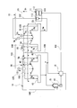
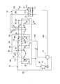
- FIG. 1 is a schematic diagram showing a configuration of a steam turbine plant according to a first embodiment of the present invention.
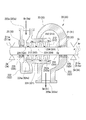
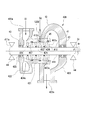
- FIG. 2 is a cross-sectional view of the high-pressure side steam turbine constituting the steam turbine plant according to the first embodiment of the present invention.
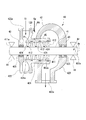
- FIG. 3 is a cross-sectional view of the low-pressure side steam turbine constituting the steam turbine plant according to the first embodiment of the present invention.
- FIG. 4 is a diagram showing a supply form of ground steam when starting the steam turbine plant according to the first embodiment of the present invention. As shown in FIG.
- the steam turbine plant 10 of this embodiment includes a boiler 11, a high-pressure steam turbine (high-pressure side steam turbine) 20, an intermediate-pressure steam turbine (high-pressure side steam turbine) 30, and a low-pressure steam turbine ( Low pressure side steam turbine) 40, condenser 15, condensate pump 16, and steam seal mechanism 50 are mainly provided.
- the boiler 11 generates steam.
- the heat source of the boiler 11 is not questioned at all.
- the heat of exhaust gas from a gas turbine (not shown) may be used.
- the boiler 11 includes an evaporator 111, a superheater 112, and a reheater 113.
- the high-pressure steam turbine 20 includes a high-pressure casing 22 into which steam flows from a high-pressure steam line 101, a high-pressure turbine rotor 21 provided in the high-pressure casing 22, and a high-pressure gland portion 23. Prepare.
- the high-pressure casing 22 is provided on the cylindrical casing 221, the inlet scroll 222 provided on the first side of the casing 221 in the axis Ar direction, and the second side of the casing 221 in the axis Ar direction. And an exit scroll 223.
- the high-pressure steam Sh generated in the boiler 11 flows into the vehicle compartment 221 from the steam suction port 222 a formed in the inlet scroll 222 through the high-pressure steam line 101.
- the inflowing high-pressure steam Sh flows in the passenger compartment 221 from the entrance scroll 222 side to the exit scroll 223 side, and is discharged to the outside from a steam discharge port 223a formed in the exit scroll 223.
- a plurality of stages of stationary blade rows 224 provided at intervals in the axis Ar direction are provided on the inner peripheral side of the casing 221.
- Each stationary blade row 224 includes a plurality of stationary blades 224a at intervals in the circumferential direction Dr around the axis Ar.
- the high-pressure turbine rotor 21 includes a rotating shaft 211 that extends along the axis Ar direction, and a moving blade row 212 that is integrally provided on the radially outer side of the rotating shaft 211.
- the rotating shaft 211 is provided such that both end portions 211 a and 211 a thereof face the outside of the high-pressure casing 22 from openings 225 and 225 formed on both sides of the high-pressure casing 22 in the axis Ar direction. Both ends 211a and 211a of the rotating shaft 211 are supported on the outside of the high-pressure casing 22 by bearings 24 so as to be rotatable around the axis Ar.
- the moving blade row 212 is formed integrally with the outer peripheral portion of the rotating shaft 211.
- the moving blade rows 212 are provided in a plurality of stages at intervals in the direction of the axis Ar of the rotating shaft 211.
- the moving blade row 212 of each stage is arranged at an interval in the axis Ar direction with respect to each stage of the stationary blade row 224 provided in a plurality of stages.
- Each moving blade row 212 includes a plurality of moving blades 212a at intervals in the circumferential direction Dr around the axis Ar.
- the swirl flow of the high-pressure steam Sh generated in the stationary blade row 224 of each stage hits the moving blade 212 a of each rotor blade row 212, so that the rotor blade row 212 and the rotating shaft 211 of each stage. Rotate integrally around the axis Ar.
- the high-pressure gland part 23 is configured such that a part of the high-pressure steam Sh in the passenger compartment 221 flows as the ground steam Sg into the gap between the opening 225 of the high-pressure casing 22 and the end 211a of the high-pressure turbine rotor 21. Seal.
- the ground vapor Sg that has flowed into the high-pressure ground unit 23 is discharged to the ground regulator line 110 described later. Further, a part of the ground vapor Sg flowing into the high-voltage ground part 23 is sucked out to the ground capacitor line 130.
- the high-pressure steam Sh sent from the boiler 11 through the high-pressure steam line 101 rotates the high-pressure turbine rotor 21 while decompressing and expanding in the passenger compartment 221.
- the high pressure steam turbine 20 outputs the rotational force of the rotating shaft 211 of the high pressure turbine rotor 21 to the outside.
- the intermediate pressure steam turbine 30 is fed with the intermediate pressure steam line 102 through which the high pressure steam Sh discharged from the high pressure steam turbine 20 is decompressed and expanded. As shown in FIG. 2, the intermediate pressure steam line 102 passes through a reheater 113 provided in the boiler 11, whereby the intermediate pressure steam Sm discharged from the high pressure steam turbine 20 is reheated. Is heated.
- the intermediate pressure steam turbine 30 includes an intermediate pressure casing 32 into which steam flows from the intermediate pressure steam line 102, an intermediate pressure turbine rotor 31 provided in the intermediate pressure casing 32, and an intermediate pressure ground portion 33. .
- the intermediate pressure casing 32 is provided on the cylindrical casing 321, the inlet scroll 322 provided on the first side of the casing 321 in the axis Ar direction, and the second side of the casing 321 in the axis Ar direction. And an exit scroll 323.
- the intermediate pressure steam Sm discharged from the high pressure steam turbine 20 flows into the vehicle interior 321 through the intermediate pressure steam line 102 from a steam suction port 322 a formed in the inlet scroll 322.
- the inflowing intermediate pressure steam Sm flows in the passenger compartment 321 from the inlet scroll 322 side to the outlet scroll 323 side, and is discharged to the outside from a steam discharge port 323 a formed in the outlet scroll 323.
- a plurality of stages of stationary blade rows 324 are provided on the inner peripheral side of the passenger compartment 321 so as to be spaced apart from each other in the direction of the axis Ar.
- Each stationary blade row 324 includes a plurality of stationary blades 324a at intervals in the circumferential direction Dr around the axis Ar.
- the intermediate pressure turbine rotor 31 includes a rotating shaft 311 extending along the axis Ar direction, and a moving blade row 312 provided integrally on the radially outer side of the rotating shaft 311.
- the rotating shaft 311 is provided so that both end portions 311a and 311a thereof face outward from openings 325 and 325 formed on both sides of the intermediate pressure casing 32 in the axis Ar direction. Both ends 311a and 311a of the rotating shaft 311 are supported by the bearings 34 so as to be rotatable around the axis Ar on the outside of the intermediate pressure casing 32.
- the moving blade row 312 is integrally formed on the outer peripheral portion of the rotating shaft 311.
- the moving blade rows 312 are provided in a plurality of stages at intervals in the axis Ar direction of the rotating shaft 311.
- the moving blade row 312 of each stage is arranged at intervals in the axis Ar direction with respect to each stage of the stationary blade row 324 provided in a plurality of stages.
- Each moving blade row 312 is provided with a plurality of moving blades 312a at intervals in the circumferential direction Dr around the axis Ar.
- the intermediate pressure turbine rotor 31 rotates with the moving blade row 312 of each stage by the swirling flow of the intermediate pressure steam Sm generated by the stationary blade row 324 of each stage hitting the moving blade 312a of each moving blade row 312.
- the shaft 311 rotates integrally around the axis Ar.
- the intermediate pressure gland portion 33 is configured such that a part of the intermediate pressure steam Sm in the passenger compartment 321 flows into the gap between the opening 325 of the intermediate pressure casing 32 and the end 311a of the intermediate pressure turbine rotor 31 as the ground steam Sg. , Seal this gap.
- the ground vapor Sg that has flowed into the intermediate pressure ground portion 33 is discharged to the ground regulator line 110 described later. Further, a part of the ground vapor Sg flowing into the intermediate pressure ground part 33 is sucked into the ground capacitor line 130.
- the intermediate pressure steam turbine 30 is fed with the intermediate pressure steam Sm via the intermediate pressure steam line 102.
- the intermediate pressure steam Sm rotates and drives the intermediate pressure turbine rotor 31 while decompressing and expanding in the vehicle interior 321 of the intermediate pressure steam turbine 30.
- the intermediate pressure steam turbine 30 outputs the rotational force of the rotation shaft 311 of the intermediate pressure turbine rotor 31 to the outside.
- the low-pressure steam Sl discharged from the medium-pressure steam turbine 30 after the medium-pressure steam Sm is decompressed and expanded is fed through the low-pressure steam line 103.
- the low pressure steam turbine 40 includes a low pressure casing 42 into which steam flows from the low pressure steam line 103, a low pressure turbine rotor 41 provided in the low pressure casing 42, and a low pressure ground portion 43.
- the low-pressure casing 42 is provided on the cylindrical casing 421, the inlet scroll 422 provided on the first side of the casing 421 in the axis Ar direction, and the second side of the casing 421 in the axis Ar direction. And an exit scroll 423.
- the low-pressure steam Sl discharged from the high-pressure steam turbine 20 flows into the vehicle compartment 421 from the steam inlet 422 a formed in the inlet scroll 422 through the low-pressure steam line 103.
- the low-pressure steam Sl that has flowed flows in the passenger compartment 421 from the inlet scroll 422 side toward the outlet scroll 423 side, and is discharged to the outside from a steam discharge port 423a formed in the outlet scroll 423.
- a plurality of stages of stationary blade rows 424 provided at intervals in the axis Ar direction are provided on the inner peripheral side of the passenger compartment 421.
- Each stationary blade row 424 includes a plurality of stationary blades 424a at intervals in the circumferential direction Dr around the axis Ar.
- the low-pressure turbine rotor 41 includes a rotating shaft 411 extending along the axis Ar direction, and a moving blade row 412 provided integrally on the radially outer side of the rotating shaft 411.
- the rotating shaft 411 is provided such that both end portions 411a and 411a thereof face outward from openings 425 and 425 formed on both sides of the low-pressure casing 42 in the axis Ar direction. Both ends 411a and 411a of the rotating shaft 411 are supported on the outside of the low-pressure casing 42 by bearings 44 so as to be rotatable around the axis Ar.
- the moving blade row 412 is formed integrally with the outer peripheral portion of the rotating shaft 411.
- the moving blade rows 412 are provided in a plurality of stages at intervals in the direction of the axis Ar of the rotating shaft 411.
- the moving blade row 412 of each stage is arranged at an interval in the axis Ar direction with respect to each stage of the stationary blade row 424 provided in a plurality of stages.
- Each blade array 412 is provided with a plurality of blades 412a at intervals in the circumferential direction Dr around the axis Ar.
- the rotating blade row 412 of each stage and the rotating shaft 411 are brought into contact with the rotating blade 412 a of each moving blade row 412 by the swirling flow of the low-pressure steam Sl generated in the stationary blade row 424 of each stage. Rotate integrally around the axis Ar.
- a main steam flow path (flow path) 45 in which a low-pressure steam Sl flows in an annular space between the inner peripheral surface of the passenger compartment 421 and the outer peripheral surface of the rotary shaft 411 of the low-pressure turbine rotor 41. It is said that.
- the low-pressure gland portion 43 seals the gap by supplying the ground steam Sg flowing through the gland regulator line 110 to the gap between the opening 425 of the low-pressure casing 42 and the end 411a of the low-pressure turbine rotor 41. .
- the ground vapor Sg flowing into the low-pressure ground part 43 is discharged to the ground capacitor line 130 described later.
- the low-pressure steam Sl is fed into the low-pressure steam turbine 40 through the low-pressure steam line 103.
- the low-pressure steam Sl rotates the low-pressure turbine rotor 41 while decompressing and expanding in the passenger compartment 421 of the low-pressure steam turbine 40.
- the low pressure steam turbine 40 outputs the rotational force of the rotating shaft 411 of the low pressure turbine rotor 41 to the outside.
- the condenser 15 is connected to a low pressure casing 42 of the low pressure steam turbine 40.
- the steam discharged from the low-pressure steam turbine 40 flows into the condenser 15 and returns the steam to water by heat exchange.
- the condenser pump 16 is provided in a water supply line 105 that connects the condenser 15 and the boiler 11, and sends the water in the condenser 15 to the boiler 11.
- the steam seal mechanism 50 includes a ground regulator line 110, a rotor drive steam supply line 120, and a ground capacitor line 130.
- the ground regulator line 110 guides the ground vapor Sg from the high-pressure ground part 23 and the intermediate-pressure ground part 33 to the low-pressure ground part 43.
- the ground condenser line 130 collects ground steam Sg discharged from the high pressure ground section 23 of the high pressure steam turbine 20, the medium pressure ground section 33 of the intermediate pressure steam turbine 30, and the low pressure ground section 43 of the low pressure steam turbine 40 to collect the ground condenser.
- the ground condenser 18 exchanges heat between the water flowing through the water supply line 105 and the ground steam Sg fed through the ground condenser line 130. Thereby, the water from the condenser 15 is heated, and the ground steam Sg is cooled.
- the ground steam Sg cooled by the ground condenser 18 is sent to the condenser 15 through the connection pipe 106 and returned to the water.
- the rotor drive steam supply line 120 is a line branched from the ground regulator line 110.
- the rotor-driven steam supply line 120 is configured so that a part of the ground steam Sg fed from the high-pressure ground portion 23 of the high-pressure steam turbine 20 and the intermediate-pressure ground portion 33 of the intermediate-pressure steam turbine 30 through the ground regulator line 110 is transferred into the low-pressure casing 42. Is supplied to the main steam flow path 45 for rotating the low-pressure turbine rotor 41.
- the rotor drive steam supply line 120 is connected to a portion in the low pressure casing 42 where the pressure P1 is lower than the pressure P0 of the ground steam Sg supplied from the ground regulator line 110. .
- the rotor-driven steam supply line 120 includes the second and subsequent stages excluding the most upstream side in the steam flow direction in the main steam channel 45 of the low-pressure casing 42 in the plurality of stages of stationary blade rows 424.
- the low pressure casing 42 is connected to the upstream side of the stationary blade row 424 and the downstream side of the moving blade row 412 disposed upstream of the stationary blade row 424.
- the ground steam Sg fed through the rotor drive steam supply line 120 joins with the steam in the passenger compartment 421 flowing through the main steam flow path 45, and rotates the low-pressure turbine rotor 41.
- the steam seal mechanism 50 includes a temperature reducer 55 for reducing the temperature of the ground steam Sg flowing through the rotor driving steam supply line 120 and the flow rate of the ground steam Sg flowing through the rotor driving steam supply line 120.
- a correlation value detector 56s for detecting a steam flow rate correlation value correlated with the flow rate of the ground steam Sg flowing through the ground regulator line 110.
- the flow rate adjusting valve 56 opens when the steam flow rate correlation value detected by the correlation value detector 56s is equal to or greater than a predetermined value, and increases the flow rate of the ground steam Sg flowing through the rotor drive steam supply line 120.
- the steam flow rate correlation value detected by the correlation value detector 56s includes, for example, the flow rate of the ground steam Sg, the pressure P0 of the ground steam Sg, the plant output of the steam turbine plant 10, and the like.
- the steam seal mechanism 50 includes an exhaust line 140 that branches from the ground regulator line 110 and reaches the condenser 15.
- the exhaust line 140 is provided with an on-off valve 19 that connects and disconnects the exhaust line 140.
- the amount of steam generated in the boiler 11 is that of the high-pressure ground portion 23 of the high-pressure steam turbine 20 and the medium-pressure steam turbine 30.
- the intermediate pressure gland 33 and the low pressure gland 43 of the low pressure steam turbine 40 are not sufficiently sealed.
- the on-off valve 19 provided in the exhaust line 140 and the flow rate adjusting valve 56 provided in the ground regulator line 110 are closed.
- the low-pressure gland 43 of the low-pressure steam turbine 40 can be supplied with gland steam Sg from an auxiliary boiler (not shown) connected to the gland regulator line 110 to seal the low-pressure gland 43.
- the open / close valve 19 provided in the exhaust line 140 is opened when a predetermined time has elapsed after the start of the steam turbine plant 10 or when the steam flow rate correlation value becomes a certain value or more.
- the flow rate of the ground steam Sg sent from the ground regulator line 110 to the low-pressure gland portion 43 becomes a flow rate sufficient for sealing the low-pressure gland portion 43. Therefore, after this time, the flow rate of the ground steam Sg flowing through the ground regulator line 110 exceeds the steam flow rate necessary for sealing the low-pressure ground part 43. Therefore, as described above, the on-off valve 19 is opened, and the excess steam excluding the steam necessary for sealing the low-pressure gland portion 43 out of the ground steam Sg flowing through the ground regulator line 110 is recovered via the exhaust line 140. Send to water bottle 15. In the condenser 15, the ground steam Sg from the exhaust line 140 is returned to water.
- a part of the steam Sg is supplied to a steam main steam flow path 45 that rotates the low-pressure turbine rotor 41 in the low-pressure casing 42 of the low-pressure steam turbine 40.
- a part of the ground steam Sg can be used as energy for rotating the low-pressure turbine rotor 41.
- the energy of the ground steam Sg can be effectively used by directly rotating the low-pressure turbine rotor 41 with the ground steam Sg. Therefore, the plant efficiency in the steam turbine plant 10 can be improved.
- the rotor drive steam supply line 120 supplies a part of the ground steam Sg to a portion of the low pressure casing 42 where the pressure is lower than the ground steam Sg supplied from the ground regulator line 110.
- the ground steam Sg can be efficiently supplied into the low pressure casing 42 through the rotor driving steam supply line 120.
- the low-pressure turbine rotor 41 can be rotated more efficiently.
- the steam seal mechanism 50 includes a flow rate adjusting valve 56 that adjusts the flow rate of the ground steam Sg flowing through the rotor drive steam supply line 120.
- a flow rate adjusting valve 56 that adjusts the flow rate of the ground steam Sg flowing through the rotor drive steam supply line 120.
- the flow rate adjusting valve 56 is opened when the steam flow rate correlation value detected by the correlation value detector 56s is equal to or greater than a predetermined value.
- the flow rate of the ground steam Sg sent out from the high-pressure steam turbine 20 and the intermediate-pressure steam turbine 30 exceeds the flow rate of the ground steam Sg required by the low-pressure steam turbine 40, and the surplus ground steam Sg is generated.
- the excess ground steam Sg is effectively used as drive energy for rotating the low-pressure turbine rotor 41 of the low-pressure steam turbine 40 by increasing the flow rate of the ground steam Sg flowing through the rotor-driven steam supply line 120. Can do.
- the rotor-driven steam supply line 120 is upstream of the second and subsequent stator blade rows 424 excluding the most upstream side in the steam flow direction in the low-pressure casing 42 among the plurality of stator blade rows 424.
- the low pressure casing 42 is connected to the downstream side of the moving blade row 412 arranged on the upstream side of the stationary blade row 424. According to such a structure, it can suppress that rotation of the moving blade row
- FIG. 5 is a cross-sectional view of the low-pressure side steam turbine constituting the steam turbine plant according to the second embodiment of the present invention.
- the rotor drive steam supply line 120 ⁇ / b> B in the low-pressure steam turbine 40 ⁇ / b> B in this embodiment includes at least one stage of the moving blade row 412 among the plurality of moving blade rows 412 provided in the low-pressure steam turbine 40. It is connected so as to face radially outward.
- the rotor driving steam supply line 120B is connected to a position facing the tip 412c provided at the tip of the moving blade 412a of the moving blade row 412 from the radially outer side.
- the ground steam Sg supplied into the low pressure casing 42 through the rotor driving steam supply line 120B is sent from a position facing the radially outer side of the moving blade row 412.
- the ground steam Sg supplied into the low-pressure casing 42 through the rotor-driven steam supply line 120 is sent from the position facing the radially outer side of the moving blade row 412, so It is possible to suppress the steam Sg from inhibiting the rotation of the moving blade row 412. Further, the ground steam Sg fed from the rotor driving steam supply line 120 can improve the sealing performance of the gap between the outer peripheral portion of the low-pressure turbine rotor 41 and the inner peripheral surface of the low-pressure casing 42 on the outer peripheral side.
- temperature reducers 55 may be provided in both the ground regulator line 110 and the rotor drive steam supply line 120.
- the steam turbine plant 10 of the first and second embodiments includes the exhaust line 140
- the exhaust line 140 may be omitted.
- the flow rate adjustment valve 56 is opened at basically the same timing as when the opening / closing valve 19 is opened.
- the high-pressure casing 22 and the intermediate-pressure casing 32 are connected to each other to form a single casing.
- the low pressure casing 42 is independent of the high pressure casing 22 and the intermediate pressure casing 32.
- the connection relationship between the casings 22, 32, 42 of the steam turbines 20, 30, 40 is not limited to the above form.
- the high-pressure casing 22, the intermediate-pressure casing 32, and the low-pressure casing 42 may be connected to each other to form a single casing.
- the intermediate pressure casing 32 and the low pressure casing 42 may be connected to each other to form one casing, and the high pressure casing 22 may be independent from the other casings.
- the high-pressure casing 22, the intermediate-pressure casing 32, and the low-pressure casing 42 may be independent from each other.
Abstract
A steam turbine plant (10) is provided with a high-pressure gland portion (23), a low-pressure gland portion (43), a gland regulator line (110) and a rotor drive steam supply line (120). The high-pressure gland portion (23) seals a gap at an end portion of a high-pressure turbine rotor by supplying gland steam (Sg) into the gap. The low-pressure gland portion (43) seals a gap at an end portion of a low-pressure turbine rotor by supplying gland steam (Sg) into the gap. The gland regulator line (110) guides the gland steam (Sg) from the high-pressure gland portion (23) to the low-pressure gland portion (43). The rotor drive steam supply line (120) branches from the gland regulator line (110) and supplies part of the gland steam (Sg) to a main steam flow passage inside a low-pressure casing.
Description
本発明は、複数の蒸気タービンを備える蒸気タービンプラントに関する。
本願は、2017年2月17日に日本国に出願された特願2017-027918号に基づき優先権を主張し、この内容をここに援用する。 The present invention relates to a steam turbine plant including a plurality of steam turbines.
This application claims priority based on Japanese Patent Application No. 2017-027918 filed in Japan on February 17, 2017, the contents of which are incorporated herein by reference.
蒸気タービンは、ロータの回転軸の端部が、ケーシングに形成された開口部を貫通して外部に突出している。このような蒸気タービンでは、ケーシングの開口部と回転軸との隙間に蒸気を通すことで、回転軸の端部におけるシール性を確保している。高圧側蒸気タービンと、低圧側蒸気タービンとを備える蒸気タービンプラントの場合、高圧側蒸気タービンでは、タービンケーシングの内部は大気圧よりも高圧である。このため、高圧側蒸気タービンの回転軸の端部において、ケーシングの開口部と回転軸との隙間を通してタービンケーシングの内部から外部に向かって蒸気(以下、この蒸気をグランド蒸気と適宜称する)が流れ出ることで、回転軸の端部におけるシール性を確保している。一方、低圧側蒸気タービンでは、タービンケーシングの内部は大気圧よりも低圧である。このため、低圧側蒸気タービンでは、ケーシングの開口部と回転軸との隙間を通して外部からケーシングの内部に空気が入り込みやすい。そこで、高圧側蒸気タービンのケーシングの開口部と回転軸の端部との隙間を通ったグランド蒸気を、低圧側蒸気タービンのケーシングの開口部と回転軸との隙間に供給することで、この回転軸の端部におけるシール性を確保している。
In the steam turbine, the end of the rotating shaft of the rotor protrudes outside through an opening formed in the casing. In such a steam turbine, the steam is passed through the gap between the opening of the casing and the rotating shaft, thereby ensuring the sealing performance at the end of the rotating shaft. In the case of a steam turbine plant including a high-pressure side steam turbine and a low-pressure side steam turbine, in the high-pressure side steam turbine, the inside of the turbine casing has a pressure higher than the atmospheric pressure. For this reason, at the end of the rotary shaft of the high-pressure side steam turbine, steam flows out from the inside of the turbine casing to the outside through the gap between the opening of the casing and the rotary shaft (hereinafter, this steam is appropriately referred to as ground steam). Thus, the sealing performance at the end of the rotating shaft is secured. On the other hand, in the low pressure side steam turbine, the inside of the turbine casing has a pressure lower than the atmospheric pressure. For this reason, in the low pressure side steam turbine, air easily enters the inside of the casing from the outside through the gap between the opening of the casing and the rotating shaft. Therefore, the ground steam that has passed through the gap between the opening of the casing of the high-pressure side steam turbine and the end of the rotating shaft is supplied to the gap between the opening of the casing of the low-pressure side steam turbine and the rotating shaft. The seal at the end of the shaft is secured.
ところで、上記したような蒸気タービンプラントにおいては、各蒸気タービンの作動状態に応じて、高圧側蒸気タービンから低圧側蒸気タービンに供給されるグランド蒸気の流量が変動する。すなわち、蒸気タービンプラントの起動時においては、高圧側蒸気タービンから低圧側蒸気タービンに供給されるグランド蒸気の流量が少ない。また、蒸気タービンプラントが定格運転状態となったときには、高圧側蒸気タービンから低圧側蒸気タービンに供給されるグランド蒸気の流量が多くなる。
Incidentally, in the steam turbine plant as described above, the flow rate of the ground steam supplied from the high-pressure side steam turbine to the low-pressure side steam turbine varies depending on the operating state of each steam turbine. That is, when the steam turbine plant is started, the flow rate of the ground steam supplied from the high pressure side steam turbine to the low pressure side steam turbine is small. Further, when the steam turbine plant is in the rated operation state, the flow rate of the ground steam supplied from the high pressure side steam turbine to the low pressure side steam turbine increases.
例えば、特許文献1には、高圧側蒸気タービンから低圧側蒸気タービンに供給されるグランド蒸気の流量が、低圧側蒸気タービンで必要としている蒸気量を上回った場合に、余剰分のグランド蒸気を、蒸気タービンプラントに設けられた復水器に送り込んで復水させる構成が開示されている。
しかし、余剰分のグランド蒸気を復水器で熱交換したのでは、グランド蒸気が有する熱エネルギーを捨てることになる。そこで、特許文献1には、復水器から出た水と熱交換するグランド蒸気復水器に、余剰分のグランド蒸気を供給する構成も開示されている。この構成によれば、余剰分の蒸気をグランド復水器に供給することで、余剰分のグランド蒸気を復水器に送り込む場合に比較し、熱エネルギーの効率を高めることができる。 For example, in Patent Document 1, when the flow rate of ground steam supplied from the high-pressure side steam turbine to the low-pressure side steam turbine exceeds the amount of steam required by the low-pressure side steam turbine, surplus ground steam is A configuration is disclosed in which a condensate is sent to a condenser provided in a steam turbine plant.
However, if the excess ground steam is heat-exchanged by the condenser, the heat energy of the ground steam is discarded. Therefore, Patent Document 1 discloses a configuration in which surplus ground steam is supplied to a ground steam condenser that exchanges heat with water discharged from the condenser. According to this configuration, by supplying surplus steam to the ground condenser, the efficiency of thermal energy can be increased as compared with the case where surplus ground steam is fed into the condenser.
しかしながら、特許文献1に記載の技術では、余剰分のグランド蒸気を、復水器又はグランド復水器に放出しているため、グランド蒸気を有効利用できているとは言い切れず、プラント効率には向上の余地がある。
However, in the technique described in Patent Document 1, since surplus ground steam is discharged to the condenser or the ground condenser, it cannot be said that the ground steam can be effectively used, and the plant efficiency is improved. There is room for improvement.
そこで、本発明は、グランド蒸気の有効利用を図り、プラント効率を向上させることができる蒸気タービンプラントを提供することを目的とする。
Therefore, an object of the present invention is to provide a steam turbine plant capable of effectively using ground steam and improving plant efficiency.
前記目的を達成するための発明に係る一態様としての蒸気タービンプラントは、内部に蒸気が流入する高圧ケーシング、及び前記高圧ケーシング内に設けられるとともにその両端部が前記高圧ケーシングに形成された開口部から外方に臨み、前記高圧ケーシング内に流入した前記蒸気により回転する高圧タービンロータ、を有する高圧側蒸気タービンと、前記高圧側蒸気タービンから排気された前記蒸気が流入する低圧ケーシング、及び前記低圧ケーシング内に設けられるとともに、その両端部が前記低圧ケーシングに形成された開口部から外方に臨み、前記低圧ケーシング内に流入した前記蒸気により回転する低圧タービンロータ、を有する低圧側蒸気タービンと、を備える。前記高圧側蒸気タービンは、前記高圧ケーシングの前記開口部と前記高圧タービンロータの端部との隙間に前記蒸気をグランド蒸気として供給することで前記隙間をシールする高圧グランド部を有する。また、前記低圧側蒸気タービンは、前記低圧ケーシングの前記開口部と前記低圧タービンロータの前記端部との隙間に前記グランド蒸気を供給することで前記隙間をシールする低圧グランド部を有する。この蒸気タービンプラントは、さらに、前記高圧グランド部から前記低圧グランド部に前記グランド蒸気を導くグランドレギュレータラインと、前記グランドレギュレータラインから分岐し、前記グランド蒸気の一部を、前記低圧ケーシング内で前記低圧タービンロータを回転させる前記蒸気の流路に供給するロータ駆動蒸気供給ラインと、を備える。
A steam turbine plant as one aspect according to the invention for achieving the above object includes a high-pressure casing into which steam flows and an opening formed in the high-pressure casing at both ends thereof. A high-pressure side steam turbine having a high-pressure turbine rotor rotating outward by the steam flowing into the high-pressure casing, a low-pressure casing into which the steam exhausted from the high-pressure side steam turbine flows, and the low-pressure A low-pressure side steam turbine having a low-pressure turbine rotor that is provided in the casing and whose both ends face outward from an opening formed in the low-pressure casing and rotates by the steam flowing into the low-pressure casing; Is provided. The high-pressure-side steam turbine has a high-pressure gland part that seals the gap by supplying the steam as gland steam to the gap between the opening of the high-pressure casing and the end of the high-pressure turbine rotor. The low-pressure side steam turbine has a low-pressure gland part that seals the gap by supplying the ground steam to a gap between the opening of the low-pressure casing and the end of the low-pressure turbine rotor. The steam turbine plant further includes a ground regulator line that guides the ground steam from the high-pressure ground part to the low-pressure ground part, and a branch from the ground regulator line, and a part of the ground steam is part of the ground pressure in the low-pressure casing. A rotor drive steam supply line that supplies the steam flow path for rotating the low-pressure turbine rotor.
このような構成によれば、高圧側蒸気タービンの高圧グランド部から低圧側蒸気タービンの低圧グランド部に送り込むグランド蒸気の一部を、低圧側蒸気タービンの低圧ケーシング内で低圧タービンロータを回転させる蒸気の流路に供給する。これにより、グランド蒸気の一部を、低圧タービンロータを回転させるエネルギーとして用いることができる。このように、グランド蒸気によって低圧タービンロータを直接的に回転させることで、ロスも少なく、グランド蒸気を有効利用することができる。
According to such a configuration, a part of the ground steam fed from the high pressure gland part of the high pressure side steam turbine to the low pressure gland part of the low pressure side steam turbine is used to rotate the low pressure turbine rotor in the low pressure casing of the low pressure side steam turbine. To the flow path. Thereby, a part of ground steam can be used as energy for rotating the low-pressure turbine rotor. Thus, by rotating the low-pressure turbine rotor directly with ground steam, there is little loss and ground steam can be used effectively.
また、前記ロータ駆動蒸気供給ラインは、前記低圧ケーシング内で、前記グランドレギュレータラインから供給される前記グランド蒸気よりも圧力が低い部分に、前記グランド蒸気の一部を供給するようにしてもよい。
In addition, the rotor drive steam supply line may supply a part of the ground steam to a portion of the low pressure casing where the pressure is lower than the ground steam supplied from the ground regulator line.
このような構成によれば、ロータ駆動蒸気供給ラインを通して、グランド蒸気を低圧ケーシング内に効率良く供給することができ、低圧ケーシング内に送り込まれたグランド蒸気の流速も高まる。これによって、低圧タービンロータを、より効率良く回転させることができる。
According to such a configuration, the ground steam can be efficiently supplied into the low-pressure casing through the rotor-driven steam supply line, and the flow speed of the ground steam sent into the low-pressure casing is also increased. Thereby, the low-pressure turbine rotor can be rotated more efficiently.
また、前記ロータ駆動蒸気供給ラインを流れる前記グランド蒸気の流量を調節する流量調節弁を備えるようにしてもよい。
Further, a flow rate adjusting valve for adjusting the flow rate of the ground steam flowing through the rotor drive steam supply line may be provided.
このような構成によれば、低圧側蒸気タービンにおいて必要とされている量に応じて、低圧蒸気タービンの低圧ケーシング内へのグランド蒸気の供給量を調節することができる。
According to such a configuration, the amount of ground steam supplied into the low pressure casing of the low pressure steam turbine can be adjusted according to the amount required in the low pressure side steam turbine.
また、前記グランドレギュレータラインを流れる前記グランド蒸気の流量に相関する蒸気流量相関値を検知する相関値検知器を備えてもよい。そして、前記流量調節弁は、前記相関値検知器により検知された前記蒸気流量相関値が予め定められた値以上になると開くようにしてもよい。
Further, a correlation value detector for detecting a steam flow rate correlation value correlated with the flow rate of the ground steam flowing through the ground regulator line may be provided. The flow rate control valve may be opened when the steam flow rate correlation value detected by the correlation value detector is equal to or greater than a predetermined value.
このような構成によれば、グランドレギュレータラインを流れるグランド蒸気の流量は、高圧側蒸気タービンや低圧側蒸気タービンの作動状態に応じて変動する。例えば、蒸気タービンプラントの起動時には、グランドレギュレータラインを流れるグランド蒸気の流量は少ない。蒸気タービンプラントの起動後、高圧側蒸気タービンや低圧側蒸気タービンの作動回転数が高まるにしたがって、グランドレギュレータラインを流れるグランド蒸気の流量は増える。このような状態において、高圧側蒸気タービンから送り出されるグランド蒸気の流量が、低圧側蒸気タービンで必要としているグランド蒸気の流量を上回り、余剰のグランド蒸気が発生することがある。このようにして余剰のグランド蒸気が生じた場合に、ロータ駆動蒸気供給ラインを流れるグランド蒸気の流量を増やすことで、余剰のグランド蒸気を低圧側蒸気タービンの低圧タービンロータを回転させるための駆動エネルギーとして有効に用いることができる。
According to such a configuration, the flow rate of the ground steam flowing through the ground regulator line varies according to the operating state of the high-pressure side steam turbine and the low-pressure side steam turbine. For example, when the steam turbine plant is started, the flow rate of the ground steam flowing through the ground regulator line is small. After the start of the steam turbine plant, the flow rate of the ground steam flowing through the ground regulator line increases as the operating speed of the high-pressure side steam turbine and the low-pressure side steam turbine increases. In such a state, the flow rate of the ground steam sent out from the high pressure side steam turbine may exceed the flow rate of the ground steam required in the low pressure side steam turbine, and surplus ground steam may be generated. When surplus ground steam is generated in this way, the drive energy for rotating the low-pressure turbine rotor of the low-pressure side steam turbine is increased by increasing the flow rate of the ground steam flowing through the rotor-driven steam supply line. Can be used effectively.
また、前記低圧側蒸気タービンは、前記低圧ケーシングの内周側に固定され、前記低圧タービンロータの軸線方向に互いの間隔をあけて設けられた複数段の静翼列と、前記低圧タービンロータの外周部に形成され、各段の前記静翼列に対して、前記軸線方向に間隔をあけて設けられた複数段の動翼列と、を備えてもよい。そして、前記ロータ駆動蒸気供給ラインは、複数段の前記静翼列のうち、前記低圧ケーシング内における前記蒸気の流れ方向の最上流側を除いた2段目以降の前記静翼列の上流側であって、該静翼列の上流側に隣接配置された前記動翼列の下流側にて、前記低圧ケーシングに接続されているようにしてもよい。
The low-pressure side steam turbine is fixed to the inner peripheral side of the low-pressure casing, and is provided with a plurality of stages of stationary blade rows that are spaced apart from each other in the axial direction of the low-pressure turbine rotor, and the low-pressure turbine rotor And a plurality of stages of moving blade rows that are formed on the outer peripheral portion and are spaced from each other in the axial direction with respect to the stationary blade rows of each stage. The rotor-driven steam supply line is upstream of the second and subsequent stages of the stationary blade rows excluding the most upstream side of the steam flow direction in the low-pressure casing among the plurality of stages of stationary blade rows. Then, it may be connected to the low pressure casing on the downstream side of the moving blade row arranged adjacent to the upstream side of the stationary blade row.
このような構成によれば、ロータ駆動蒸気供給ラインを通して低圧ケーシング内に供給されるグランド蒸気を、静翼列の上流側であって、動翼列の下流側で送り込むことで、送り込んだグランド蒸気が動翼列の回転を阻害するのを抑えることができる。
According to such a configuration, the ground steam supplied into the low-pressure casing through the rotor drive steam supply line is sent upstream of the stationary blade row and downstream of the moving blade row, so that the fed ground steam is supplied. Can inhibit the rotation of the rotor blade row.
また、前記低圧側蒸気タービンは、前記低圧ケーシングの内周側に固定され、前記低圧タービンロータの軸線方向に互いの間隔をあけて設けられた複数段の静翼列と、前記低圧タービンロータの外周部に形成され、各段の前記静翼列に対して、前記軸線方向に間隔をあけて設けられた複数段の動翼列と、を備えてもよい。そして、前記ロータ駆動蒸気供給ラインは、複数段の前記動翼列のうちの少なくとも一段の径方向外側に臨むよう前記低圧ケーシングに接続されているようにしてもよい。
The low-pressure side steam turbine is fixed to the inner peripheral side of the low-pressure casing, and is provided with a plurality of stages of stationary blade rows that are spaced apart from each other in the axial direction of the low-pressure turbine rotor, and the low-pressure turbine rotor And a plurality of stages of moving blade rows that are formed on the outer peripheral portion and are spaced from each other in the axial direction with respect to the stationary blade rows of each stage. The rotor-driven steam supply line may be connected to the low-pressure casing so as to face at least one stage in the radial direction of the plurality of blade rows.
このような構成によれば、ロータ駆動蒸気供給ラインを通して低圧ケーシング内に供給されるグランド蒸気を、動翼列の径方向外側に臨む位置から送り込むことで、送り込んだグランド蒸気が動翼列の回転を阻害するのを抑えることができる。
また、ロータ駆動蒸気供給ラインから送り込んだグランド蒸気によって、低圧タービンロータの外周部と、その外周側のケーシング内周面との隙間のシール性を高めることができる。 According to such a configuration, the ground steam supplied into the low-pressure casing through the rotor-driven steam supply line is sent from the position facing the radially outer side of the rotor blade row, so that the sent ground steam rotates the rotor blade row. Can be suppressed.
Moreover, the sealing performance of the clearance gap between the outer peripheral part of a low-pressure turbine rotor and the casing inner peripheral surface of the outer peripheral side can be improved by the ground steam sent from the rotor driving steam supply line.
本発明の一態様では、グランド蒸気の有効利用を図り、プラント効率を向上させることが可能となる。
In one embodiment of the present invention, it is possible to effectively use ground steam and improve plant efficiency.
以下、添付図面を参照して、本発明による蒸気タービンプラントを実施するための形態を説明する。しかし、本発明はこれらの実施形態のみに限定されるものではない。
Hereinafter, an embodiment for implementing a steam turbine plant according to the present invention will be described with reference to the accompanying drawings. However, the present invention is not limited only to these embodiments.
(第一実施形態)
図1は、本発明の第一実施形態に係る蒸気タービンプラントの構成を示す模式図である。図2は、本発明に係る第一実施形態における蒸気タービンプラントを構成する高圧側蒸気タービンの断面図である。図3は、本発明に係る第一実施形態における蒸気タービンプラントを構成する低圧側蒸気タービンの断面図である。図4は、本発明に係る第一実施形態における蒸気タービンプラントを起動するときの、グランド蒸気の供給形態を示す線図である。
図1に示すように、本実施形態の蒸気タービンプラント10は、ボイラ11と、高圧蒸気タービン(高圧側蒸気タービン)20と、中圧蒸気タービン(高圧側蒸気タービン)30と、低圧蒸気タービン(低圧側蒸気タービン)40と、復水器15と、復水ポンプ16と、蒸気シール機構50と、を主に備えている。 (First embodiment)
FIG. 1 is a schematic diagram showing a configuration of a steam turbine plant according to a first embodiment of the present invention. FIG. 2 is a cross-sectional view of the high-pressure side steam turbine constituting the steam turbine plant according to the first embodiment of the present invention. FIG. 3 is a cross-sectional view of the low-pressure side steam turbine constituting the steam turbine plant according to the first embodiment of the present invention. FIG. 4 is a diagram showing a supply form of ground steam when starting the steam turbine plant according to the first embodiment of the present invention.
As shown in FIG. 1, thesteam turbine plant 10 of this embodiment includes a boiler 11, a high-pressure steam turbine (high-pressure side steam turbine) 20, an intermediate-pressure steam turbine (high-pressure side steam turbine) 30, and a low-pressure steam turbine ( Low pressure side steam turbine) 40, condenser 15, condensate pump 16, and steam seal mechanism 50 are mainly provided.
図1は、本発明の第一実施形態に係る蒸気タービンプラントの構成を示す模式図である。図2は、本発明に係る第一実施形態における蒸気タービンプラントを構成する高圧側蒸気タービンの断面図である。図3は、本発明に係る第一実施形態における蒸気タービンプラントを構成する低圧側蒸気タービンの断面図である。図4は、本発明に係る第一実施形態における蒸気タービンプラントを起動するときの、グランド蒸気の供給形態を示す線図である。
図1に示すように、本実施形態の蒸気タービンプラント10は、ボイラ11と、高圧蒸気タービン(高圧側蒸気タービン)20と、中圧蒸気タービン(高圧側蒸気タービン)30と、低圧蒸気タービン(低圧側蒸気タービン)40と、復水器15と、復水ポンプ16と、蒸気シール機構50と、を主に備えている。 (First embodiment)
FIG. 1 is a schematic diagram showing a configuration of a steam turbine plant according to a first embodiment of the present invention. FIG. 2 is a cross-sectional view of the high-pressure side steam turbine constituting the steam turbine plant according to the first embodiment of the present invention. FIG. 3 is a cross-sectional view of the low-pressure side steam turbine constituting the steam turbine plant according to the first embodiment of the present invention. FIG. 4 is a diagram showing a supply form of ground steam when starting the steam turbine plant according to the first embodiment of the present invention.
As shown in FIG. 1, the
ボイラ11は、蒸気を発生させる。ここで、ボイラ11の熱源は何ら問うものではなく、例えば、ガスタービン(図示無し)からの排気ガスの熱を利用してもよい。このボイラ11は、蒸発器111と、過熱器112と、再熱器113と、を備えている。
The boiler 11 generates steam. Here, the heat source of the boiler 11 is not questioned at all. For example, the heat of exhaust gas from a gas turbine (not shown) may be used. The boiler 11 includes an evaporator 111, a superheater 112, and a reheater 113.
高圧蒸気タービン20は、ボイラ11で蒸発器111及び過熱器112を経ることで生成された高圧蒸気Shが、高圧蒸気ライン101を介して送り込まれる。図2に示すように、高圧蒸気タービン20は、高圧蒸気ライン101から内部に蒸気が流入する高圧ケーシング22と、高圧ケーシング22内に設けられた高圧タービンロータ21と、高圧グランド部23と、を備える。
In the high-pressure steam turbine 20, high-pressure steam Sh generated by passing through the evaporator 111 and the superheater 112 in the boiler 11 is sent through the high-pressure steam line 101. As shown in FIG. 2, the high-pressure steam turbine 20 includes a high-pressure casing 22 into which steam flows from a high-pressure steam line 101, a high-pressure turbine rotor 21 provided in the high-pressure casing 22, and a high-pressure gland portion 23. Prepare.
高圧ケーシング22は、筒状の車室221と、車室221の軸線Ar方向の第一の側に設けられた入口スクロール222と、車室221の軸線Ar方向の第二の側に設けられた出口スクロール223と、を一体に備えている。高圧ケーシング22は、ボイラ11で生成された高圧蒸気Shが、高圧蒸気ライン101を通して入口スクロール222に形成された蒸気吸込口222aから車室221内に流入する。流入した高圧蒸気Shは、車室221内を入口スクロール222側から出口スクロール223側に向かって流れ、出口スクロール223に形成された蒸気吐出口223aから外部に吐出される。
The high-pressure casing 22 is provided on the cylindrical casing 221, the inlet scroll 222 provided on the first side of the casing 221 in the axis Ar direction, and the second side of the casing 221 in the axis Ar direction. And an exit scroll 223. In the high-pressure casing 22, the high-pressure steam Sh generated in the boiler 11 flows into the vehicle compartment 221 from the steam suction port 222 a formed in the inlet scroll 222 through the high-pressure steam line 101. The inflowing high-pressure steam Sh flows in the passenger compartment 221 from the entrance scroll 222 side to the exit scroll 223 side, and is discharged to the outside from a steam discharge port 223a formed in the exit scroll 223.
車室221の内周側には、軸線Ar方向に互いの間隔をあけて設けられた複数段の静翼列224が設けられている。各静翼列224は、軸線Ar周りの周方向Drに間隔をあけて複数の静翼224aを備えている。
A plurality of stages of stationary blade rows 224 provided at intervals in the axis Ar direction are provided on the inner peripheral side of the casing 221. Each stationary blade row 224 includes a plurality of stationary blades 224a at intervals in the circumferential direction Dr around the axis Ar.
高圧タービンロータ21は、軸線Ar方向に沿って延びる回転軸211と、回転軸211の径方向外側に一体に設けられた動翼列212と、を備える。
回転軸211は、その両端部211a,211aが、高圧ケーシング22の軸線Ar方向の両側に形成された開口部225,225から高圧ケーシング22の外方に臨むよう設けられている。回転軸211は、両端部211a,211aが、高圧ケーシング22の外側で、それぞれ軸受24によって、軸線Ar周りに回転自在に支持されている。
動翼列212は、回転軸211の外周部に一体に形成されている。動翼列212は、回転軸211の軸線Ar方向に互いに間隔をあけて複数段に設けられている。各段の動翼列212は、複数段に設けられた上記静翼列224の各段に対し、軸線Ar方向に間隔をあけて配置されている。各動翼列212は、軸線Ar周りの周方向Drに間隔をあけて複数の動翼212aを備えている。高圧タービンロータ21は、各動翼列212の動翼212aに、各段の静翼列224で生成された高圧蒸気Shの旋回流が当たることによって、各段の動翼列212と回転軸211とが軸線Ar周りに一体に回転する。 The high-pressure turbine rotor 21 includes a rotating shaft 211 that extends along the axis Ar direction, and a moving blade row 212 that is integrally provided on the radially outer side of the rotating shaft 211.
Therotating shaft 211 is provided such that both end portions 211 a and 211 a thereof face the outside of the high-pressure casing 22 from openings 225 and 225 formed on both sides of the high-pressure casing 22 in the axis Ar direction. Both ends 211a and 211a of the rotating shaft 211 are supported on the outside of the high-pressure casing 22 by bearings 24 so as to be rotatable around the axis Ar.
The movingblade row 212 is formed integrally with the outer peripheral portion of the rotating shaft 211. The moving blade rows 212 are provided in a plurality of stages at intervals in the direction of the axis Ar of the rotating shaft 211. The moving blade row 212 of each stage is arranged at an interval in the axis Ar direction with respect to each stage of the stationary blade row 224 provided in a plurality of stages. Each moving blade row 212 includes a plurality of moving blades 212a at intervals in the circumferential direction Dr around the axis Ar. In the high-pressure turbine rotor 21, the swirl flow of the high-pressure steam Sh generated in the stationary blade row 224 of each stage hits the moving blade 212 a of each rotor blade row 212, so that the rotor blade row 212 and the rotating shaft 211 of each stage. Rotate integrally around the axis Ar.
回転軸211は、その両端部211a,211aが、高圧ケーシング22の軸線Ar方向の両側に形成された開口部225,225から高圧ケーシング22の外方に臨むよう設けられている。回転軸211は、両端部211a,211aが、高圧ケーシング22の外側で、それぞれ軸受24によって、軸線Ar周りに回転自在に支持されている。
動翼列212は、回転軸211の外周部に一体に形成されている。動翼列212は、回転軸211の軸線Ar方向に互いに間隔をあけて複数段に設けられている。各段の動翼列212は、複数段に設けられた上記静翼列224の各段に対し、軸線Ar方向に間隔をあけて配置されている。各動翼列212は、軸線Ar周りの周方向Drに間隔をあけて複数の動翼212aを備えている。高圧タービンロータ21は、各動翼列212の動翼212aに、各段の静翼列224で生成された高圧蒸気Shの旋回流が当たることによって、各段の動翼列212と回転軸211とが軸線Ar周りに一体に回転する。 The high-
The
The moving
高圧グランド部23は、高圧ケーシング22の開口部225と高圧タービンロータ21の端部211aとの隙間に、車室221内の高圧蒸気Shの一部がグランド蒸気Sgとして流れ込むことで、この隙間をシールする。高圧グランド部23に流れ込んだグランド蒸気Sgは、後述するグランドレギュレータライン110に吐出される。また、高圧グランド部23に流れ込んだグランド蒸気Sgの一部は、グランドコンデンサライン130に吸い出される。
The high-pressure gland part 23 is configured such that a part of the high-pressure steam Sh in the passenger compartment 221 flows as the ground steam Sg into the gap between the opening 225 of the high-pressure casing 22 and the end 211a of the high-pressure turbine rotor 21. Seal. The ground vapor Sg that has flowed into the high-pressure ground unit 23 is discharged to the ground regulator line 110 described later. Further, a part of the ground vapor Sg flowing into the high-voltage ground part 23 is sucked out to the ground capacitor line 130.
このような高圧蒸気タービン20では、ボイラ11から高圧蒸気ライン101を介して送り込まれた高圧蒸気Shが、車室221内で減圧膨張しながら、高圧タービンロータ21を回転駆動させる。高圧蒸気タービン20は、高圧タービンロータ21の回転軸211の回転力を外部に出力する。
In such a high-pressure steam turbine 20, the high-pressure steam Sh sent from the boiler 11 through the high-pressure steam line 101 rotates the high-pressure turbine rotor 21 while decompressing and expanding in the passenger compartment 221. The high pressure steam turbine 20 outputs the rotational force of the rotating shaft 211 of the high pressure turbine rotor 21 to the outside.
中圧蒸気タービン30は、高圧蒸気タービン20で高圧蒸気Shが減圧膨張して吐出された中圧蒸気Smが、中圧蒸気ライン102を介して送り込まれる。図2に示したように、中圧蒸気ライン102は、ボイラ11に設けられた再熱器113を通っており、これによって、高圧蒸気タービン20から吐出された中圧蒸気Smは再熱器113で加熱される。中圧蒸気タービン30は、中圧蒸気ライン102から内部に蒸気が流入する中圧ケーシング32と、中圧ケーシング32内に設けられた中圧タービンロータ31と、中圧グランド部33と、を備える。
The intermediate pressure steam turbine 30 is fed with the intermediate pressure steam line 102 through which the high pressure steam Sh discharged from the high pressure steam turbine 20 is decompressed and expanded. As shown in FIG. 2, the intermediate pressure steam line 102 passes through a reheater 113 provided in the boiler 11, whereby the intermediate pressure steam Sm discharged from the high pressure steam turbine 20 is reheated. Is heated. The intermediate pressure steam turbine 30 includes an intermediate pressure casing 32 into which steam flows from the intermediate pressure steam line 102, an intermediate pressure turbine rotor 31 provided in the intermediate pressure casing 32, and an intermediate pressure ground portion 33. .
中圧ケーシング32は、筒状の車室321と、車室321の軸線Ar方向の第一の側に設けられた入口スクロール322と、車室321の軸線Ar方向の第二の側に設けられた出口スクロール323と、を一体に備えている。中圧ケーシング32は、高圧蒸気タービン20から吐出された中圧蒸気Smが、中圧蒸気ライン102を通して入口スクロール322に形成された蒸気吸込口322aから車室321内に流入する。流入した中圧蒸気Smは、車室321内を入口スクロール322側から出口スクロール323側に向かって流れ、出口スクロール323に形成された蒸気吐出口323aから外部に吐出される。
The intermediate pressure casing 32 is provided on the cylindrical casing 321, the inlet scroll 322 provided on the first side of the casing 321 in the axis Ar direction, and the second side of the casing 321 in the axis Ar direction. And an exit scroll 323. In the intermediate pressure casing 32, the intermediate pressure steam Sm discharged from the high pressure steam turbine 20 flows into the vehicle interior 321 through the intermediate pressure steam line 102 from a steam suction port 322 a formed in the inlet scroll 322. The inflowing intermediate pressure steam Sm flows in the passenger compartment 321 from the inlet scroll 322 side to the outlet scroll 323 side, and is discharged to the outside from a steam discharge port 323 a formed in the outlet scroll 323.
車室321の内周側には、軸線Ar方向に互いの間隔をあけて設けられた複数段の静翼列324が設けられている。各静翼列324は、軸線Ar周りの周方向Drに間隔をあけて複数の静翼324aを備えている。
A plurality of stages of stationary blade rows 324 are provided on the inner peripheral side of the passenger compartment 321 so as to be spaced apart from each other in the direction of the axis Ar. Each stationary blade row 324 includes a plurality of stationary blades 324a at intervals in the circumferential direction Dr around the axis Ar.
中圧タービンロータ31は、軸線Ar方向に沿って延びる回転軸311と、回転軸311の径方向外側に一体に設けられた動翼列312と、を備える。
回転軸311は、その両端部311a,311aが、中圧ケーシング32の軸線Ar方向の両側に形成された開口部325,325から外方に臨むよう設けられている。回転軸311は、両端部311a,311aが、中圧ケーシング32の外側で、それぞれ軸受34によって、軸線Ar周りに回転自在に支持されている。
動翼列312は、回転軸311の外周部に一体に形成されている。動翼列312は、回転軸311の軸線Ar方向に互いに間隔をあけて複数段に設けられている。各段の動翼列312は、複数段に設けられた上記静翼列324の各段に対し、軸線Ar方向に間隔をあけて配置されている。各動翼列312は、軸線Ar周りの周方向Drに間隔をあけて複数の動翼312aが設けられている。中圧タービンロータ31は、各動翼列312の動翼312aに、各段の静翼列324で生成された中圧蒸気Smの旋回流が当たることによって、各段の動翼列312と回転軸311とが軸線Ar周りに一体に回転する。 The intermediatepressure turbine rotor 31 includes a rotating shaft 311 extending along the axis Ar direction, and a moving blade row 312 provided integrally on the radially outer side of the rotating shaft 311.
Therotating shaft 311 is provided so that both end portions 311a and 311a thereof face outward from openings 325 and 325 formed on both sides of the intermediate pressure casing 32 in the axis Ar direction. Both ends 311a and 311a of the rotating shaft 311 are supported by the bearings 34 so as to be rotatable around the axis Ar on the outside of the intermediate pressure casing 32.
The movingblade row 312 is integrally formed on the outer peripheral portion of the rotating shaft 311. The moving blade rows 312 are provided in a plurality of stages at intervals in the axis Ar direction of the rotating shaft 311. The moving blade row 312 of each stage is arranged at intervals in the axis Ar direction with respect to each stage of the stationary blade row 324 provided in a plurality of stages. Each moving blade row 312 is provided with a plurality of moving blades 312a at intervals in the circumferential direction Dr around the axis Ar. The intermediate pressure turbine rotor 31 rotates with the moving blade row 312 of each stage by the swirling flow of the intermediate pressure steam Sm generated by the stationary blade row 324 of each stage hitting the moving blade 312a of each moving blade row 312. The shaft 311 rotates integrally around the axis Ar.
回転軸311は、その両端部311a,311aが、中圧ケーシング32の軸線Ar方向の両側に形成された開口部325,325から外方に臨むよう設けられている。回転軸311は、両端部311a,311aが、中圧ケーシング32の外側で、それぞれ軸受34によって、軸線Ar周りに回転自在に支持されている。
動翼列312は、回転軸311の外周部に一体に形成されている。動翼列312は、回転軸311の軸線Ar方向に互いに間隔をあけて複数段に設けられている。各段の動翼列312は、複数段に設けられた上記静翼列324の各段に対し、軸線Ar方向に間隔をあけて配置されている。各動翼列312は、軸線Ar周りの周方向Drに間隔をあけて複数の動翼312aが設けられている。中圧タービンロータ31は、各動翼列312の動翼312aに、各段の静翼列324で生成された中圧蒸気Smの旋回流が当たることによって、各段の動翼列312と回転軸311とが軸線Ar周りに一体に回転する。 The intermediate
The
The moving
中圧グランド部33は、中圧ケーシング32の開口部325と中圧タービンロータ31の端部311aとの隙間に、車室321内の中圧蒸気Smの一部がグランド蒸気Sgとして流れ込むことで、この隙間をシールする。中圧グランド部33に流れ込んだグランド蒸気Sgは、後述するグランドレギュレータライン110に吐出される。また、中圧グランド部33に流れ込んだグランド蒸気Sgの一部は、グランドコンデンサライン130に吸い出される。
The intermediate pressure gland portion 33 is configured such that a part of the intermediate pressure steam Sm in the passenger compartment 321 flows into the gap between the opening 325 of the intermediate pressure casing 32 and the end 311a of the intermediate pressure turbine rotor 31 as the ground steam Sg. , Seal this gap. The ground vapor Sg that has flowed into the intermediate pressure ground portion 33 is discharged to the ground regulator line 110 described later. Further, a part of the ground vapor Sg flowing into the intermediate pressure ground part 33 is sucked into the ground capacitor line 130.
このような中圧蒸気タービン30には、中圧蒸気ライン102を介して中圧蒸気Smが送り込まれる。中圧蒸気Smは、中圧蒸気タービン30の車室321内で減圧膨張しながら、中圧タービンロータ31を回転駆動させる。中圧蒸気タービン30は、中圧タービンロータ31の回転軸311の回転力を外部に出力する。
The intermediate pressure steam turbine 30 is fed with the intermediate pressure steam Sm via the intermediate pressure steam line 102. The intermediate pressure steam Sm rotates and drives the intermediate pressure turbine rotor 31 while decompressing and expanding in the vehicle interior 321 of the intermediate pressure steam turbine 30. The intermediate pressure steam turbine 30 outputs the rotational force of the rotation shaft 311 of the intermediate pressure turbine rotor 31 to the outside.
低圧蒸気タービン40は、中圧蒸気タービン30で中圧蒸気Smが減圧膨張して吐出された低圧蒸気Slが、低圧蒸気ライン103を介して送り込まれる。図3に示すように、低圧蒸気タービン40は、低圧蒸気ライン103から内部に蒸気が流入する低圧ケーシング42と、低圧ケーシング42内に設けられた低圧タービンロータ41と、低圧グランド部43と、を備える。
In the low-pressure steam turbine 40, the low-pressure steam Sl discharged from the medium-pressure steam turbine 30 after the medium-pressure steam Sm is decompressed and expanded is fed through the low-pressure steam line 103. As shown in FIG. 3, the low pressure steam turbine 40 includes a low pressure casing 42 into which steam flows from the low pressure steam line 103, a low pressure turbine rotor 41 provided in the low pressure casing 42, and a low pressure ground portion 43. Prepare.
低圧ケーシング42は、筒状の車室421と、車室421の軸線Ar方向の第一の側に設けられた入口スクロール422と、車室421の軸線Ar方向の第二の側に設けられた出口スクロール423と、を一体に備えている。低圧ケーシング42は、高圧蒸気タービン20から吐出された低圧蒸気Slが、低圧蒸気ライン103を通して入口スクロール422に形成された蒸気吸込口422aから車室421内に流入する。流入した低圧蒸気Slは、車室421内を入口スクロール422側から出口スクロール423側に向かって流れ、出口スクロール423に形成された蒸気吐出口423aから外部に吐出される。
The low-pressure casing 42 is provided on the cylindrical casing 421, the inlet scroll 422 provided on the first side of the casing 421 in the axis Ar direction, and the second side of the casing 421 in the axis Ar direction. And an exit scroll 423. In the low-pressure casing 42, the low-pressure steam Sl discharged from the high-pressure steam turbine 20 flows into the vehicle compartment 421 from the steam inlet 422 a formed in the inlet scroll 422 through the low-pressure steam line 103. The low-pressure steam Sl that has flowed flows in the passenger compartment 421 from the inlet scroll 422 side toward the outlet scroll 423 side, and is discharged to the outside from a steam discharge port 423a formed in the outlet scroll 423.
車室421の内周側には、軸線Ar方向に互いの間隔をあけて設けられた複数段の静翼列424が設けられている。各静翼列424は、軸線Ar周りの周方向Drに間隔をあけて複数の静翼424aを備えている。
A plurality of stages of stationary blade rows 424 provided at intervals in the axis Ar direction are provided on the inner peripheral side of the passenger compartment 421. Each stationary blade row 424 includes a plurality of stationary blades 424a at intervals in the circumferential direction Dr around the axis Ar.
低圧タービンロータ41は、軸線Ar方向に沿って延びる回転軸411と、回転軸411の径方向外側に一体に設けられた動翼列412と、を備える。
回転軸411は、その両端部411a,411aが、低圧ケーシング42の軸線Ar方向の両側に形成された開口部425,425から外方に臨むよう設けられている。回転軸411は、両端部411a,411aが、低圧ケーシング42の外側で、それぞれ軸受44によって、軸線Ar周りに回転自在に支持されている。
動翼列412は、回転軸411の外周部に一体に形成されている。動翼列412は、回転軸411の軸線Ar方向に互いに間隔をあけて複数段に設けられている。各段の動翼列412は、複数段に設けられた上記静翼列424の各段に対し、軸線Ar方向に間隔をあけて配置されている。各動翼列412は、軸線Ar周りの周方向Drに間隔をあけて複数の動翼412aが設けられている。低圧タービンロータ41は、各動翼列412の動翼412aに、各段の静翼列424で生成された低圧蒸気Slの旋回流が当たることによって、各段の動翼列412と回転軸411とが軸線Ar周りに一体に回転する。 The low-pressure turbine rotor 41 includes a rotating shaft 411 extending along the axis Ar direction, and a moving blade row 412 provided integrally on the radially outer side of the rotating shaft 411.
Therotating shaft 411 is provided such that both end portions 411a and 411a thereof face outward from openings 425 and 425 formed on both sides of the low-pressure casing 42 in the axis Ar direction. Both ends 411a and 411a of the rotating shaft 411 are supported on the outside of the low-pressure casing 42 by bearings 44 so as to be rotatable around the axis Ar.
The movingblade row 412 is formed integrally with the outer peripheral portion of the rotating shaft 411. The moving blade rows 412 are provided in a plurality of stages at intervals in the direction of the axis Ar of the rotating shaft 411. The moving blade row 412 of each stage is arranged at an interval in the axis Ar direction with respect to each stage of the stationary blade row 424 provided in a plurality of stages. Each blade array 412 is provided with a plurality of blades 412a at intervals in the circumferential direction Dr around the axis Ar. In the low-pressure turbine rotor 41, the rotating blade row 412 of each stage and the rotating shaft 411 are brought into contact with the rotating blade 412 a of each moving blade row 412 by the swirling flow of the low-pressure steam Sl generated in the stationary blade row 424 of each stage. Rotate integrally around the axis Ar.
回転軸411は、その両端部411a,411aが、低圧ケーシング42の軸線Ar方向の両側に形成された開口部425,425から外方に臨むよう設けられている。回転軸411は、両端部411a,411aが、低圧ケーシング42の外側で、それぞれ軸受44によって、軸線Ar周りに回転自在に支持されている。
動翼列412は、回転軸411の外周部に一体に形成されている。動翼列412は、回転軸411の軸線Ar方向に互いに間隔をあけて複数段に設けられている。各段の動翼列412は、複数段に設けられた上記静翼列424の各段に対し、軸線Ar方向に間隔をあけて配置されている。各動翼列412は、軸線Ar周りの周方向Drに間隔をあけて複数の動翼412aが設けられている。低圧タービンロータ41は、各動翼列412の動翼412aに、各段の静翼列424で生成された低圧蒸気Slの旋回流が当たることによって、各段の動翼列412と回転軸411とが軸線Ar周りに一体に回転する。 The low-
The
The moving
低圧蒸気タービン40において、車室421の内周面と、低圧タービンロータ41の回転軸411の外周面との間の断面環状の空間が、低圧蒸気Slが流れる主蒸気流路(流路)45とされている。
In the low-pressure steam turbine 40, a main steam flow path (flow path) 45 in which a low-pressure steam Sl flows in an annular space between the inner peripheral surface of the passenger compartment 421 and the outer peripheral surface of the rotary shaft 411 of the low-pressure turbine rotor 41. It is said that.
低圧グランド部43は、低圧ケーシング42の開口部425と低圧タービンロータ41の端部411aとの隙間に、グランドレギュレータライン110を介して流れ込んだグランド蒸気Sgを供給することで、この隙間をシールする。低圧グランド部43に流れ込んだグランド蒸気Sgは、後述するグランドコンデンサライン130に吐出される。
The low-pressure gland portion 43 seals the gap by supplying the ground steam Sg flowing through the gland regulator line 110 to the gap between the opening 425 of the low-pressure casing 42 and the end 411a of the low-pressure turbine rotor 41. . The ground vapor Sg flowing into the low-pressure ground part 43 is discharged to the ground capacitor line 130 described later.
このような低圧蒸気タービン40には、低圧蒸気ライン103を介して低圧蒸気Slが送り込まれる。低圧蒸気Slは、低圧蒸気タービン40の車室421内で減圧膨張しながら、低圧タービンロータ41を回転駆動させる。低圧蒸気タービン40は、低圧タービンロータ41の回転軸411の回転力を外部に出力する。
The low-pressure steam Sl is fed into the low-pressure steam turbine 40 through the low-pressure steam line 103. The low-pressure steam Sl rotates the low-pressure turbine rotor 41 while decompressing and expanding in the passenger compartment 421 of the low-pressure steam turbine 40. The low pressure steam turbine 40 outputs the rotational force of the rotating shaft 411 of the low pressure turbine rotor 41 to the outside.
復水器15は、低圧蒸気タービン40の低圧ケーシング42に接続されている。復水器15は、低圧蒸気タービン40から排気された蒸気が流入し、この蒸気を熱交換により水に戻す。
復水ポンプ16は、復水器15とボイラ11とを接続する給水ライン105に設けられ、復水器15内の水をボイラ11に送る。 Thecondenser 15 is connected to a low pressure casing 42 of the low pressure steam turbine 40. The steam discharged from the low-pressure steam turbine 40 flows into the condenser 15 and returns the steam to water by heat exchange.
Thecondenser pump 16 is provided in a water supply line 105 that connects the condenser 15 and the boiler 11, and sends the water in the condenser 15 to the boiler 11.
復水ポンプ16は、復水器15とボイラ11とを接続する給水ライン105に設けられ、復水器15内の水をボイラ11に送る。 The
The
蒸気シール機構50は、グランドレギュレータライン110と、ロータ駆動蒸気供給ライン120と、グランドコンデンサライン130と、を備えている。
グランドレギュレータライン110は、高圧グランド部23及び中圧グランド部33から低圧グランド部43にグランド蒸気Sgを導く。 Thesteam seal mechanism 50 includes a ground regulator line 110, a rotor drive steam supply line 120, and a ground capacitor line 130.
Theground regulator line 110 guides the ground vapor Sg from the high-pressure ground part 23 and the intermediate-pressure ground part 33 to the low-pressure ground part 43.
グランドレギュレータライン110は、高圧グランド部23及び中圧グランド部33から低圧グランド部43にグランド蒸気Sgを導く。 The
The
グランドコンデンサライン130は、高圧蒸気タービン20の高圧グランド部23、中圧蒸気タービン30の中圧グランド部33、低圧蒸気タービン40の低圧グランド部43から吐出されるグランド蒸気Sgを回収してグランドコンデンサ18に送り込む。グランドコンデンサ18は、給水ライン105を流れる水と、グランドコンデンサライン130を通して送り込まれたグランド蒸気Sgとを熱交換させる。これにより、復水器15からの水は加熱され、グランド蒸気Sgは冷却される。グランドコンデンサ18で冷却されたグランド蒸気Sgは、接続配管106を通して復水器15に送り込まれ、水に戻される。
The ground condenser line 130 collects ground steam Sg discharged from the high pressure ground section 23 of the high pressure steam turbine 20, the medium pressure ground section 33 of the intermediate pressure steam turbine 30, and the low pressure ground section 43 of the low pressure steam turbine 40 to collect the ground condenser. 18 The ground condenser 18 exchanges heat between the water flowing through the water supply line 105 and the ground steam Sg fed through the ground condenser line 130. Thereby, the water from the condenser 15 is heated, and the ground steam Sg is cooled. The ground steam Sg cooled by the ground condenser 18 is sent to the condenser 15 through the connection pipe 106 and returned to the water.
ロータ駆動蒸気供給ライン120は、グランドレギュレータライン110から分岐したラインである。このロータ駆動蒸気供給ライン120は、高圧蒸気タービン20の高圧グランド部23、中圧蒸気タービン30の中圧グランド部33からグランドレギュレータライン110を通して送り込まれるグランド蒸気Sgの一部を、低圧ケーシング42内で低圧タービンロータ41を回転させる蒸気の主蒸気流路45に供給する。ここで、図3に示すように、ロータ駆動蒸気供給ライン120は、低圧ケーシング42内で、グランドレギュレータライン110から供給されるグランド蒸気Sgの圧力P0よりも圧力P1が低い部分に接続されている。具体的には、ロータ駆動蒸気供給ライン120は、複数段の静翼列424のうち、低圧ケーシング42の主蒸気流路45において、蒸気の流れ方向の最上流側を除いた2段目以降の静翼列424の上流側、かつこの静翼列424の上流側に配置された動翼列412の下流側にて、低圧ケーシング42内に接続されている。
このロータ駆動蒸気供給ライン120を通して送り込まれたグランド蒸気Sgは、主蒸気流路45を流れる車室421内の蒸気と合流し、低圧タービンロータ41を回転させる。 The rotor drivesteam supply line 120 is a line branched from the ground regulator line 110. The rotor-driven steam supply line 120 is configured so that a part of the ground steam Sg fed from the high-pressure ground portion 23 of the high-pressure steam turbine 20 and the intermediate-pressure ground portion 33 of the intermediate-pressure steam turbine 30 through the ground regulator line 110 is transferred into the low-pressure casing 42. Is supplied to the main steam flow path 45 for rotating the low-pressure turbine rotor 41. Here, as shown in FIG. 3, the rotor drive steam supply line 120 is connected to a portion in the low pressure casing 42 where the pressure P1 is lower than the pressure P0 of the ground steam Sg supplied from the ground regulator line 110. . Specifically, the rotor-driven steam supply line 120 includes the second and subsequent stages excluding the most upstream side in the steam flow direction in the main steam channel 45 of the low-pressure casing 42 in the plurality of stages of stationary blade rows 424. The low pressure casing 42 is connected to the upstream side of the stationary blade row 424 and the downstream side of the moving blade row 412 disposed upstream of the stationary blade row 424.
The ground steam Sg fed through the rotor drivesteam supply line 120 joins with the steam in the passenger compartment 421 flowing through the main steam flow path 45, and rotates the low-pressure turbine rotor 41.
このロータ駆動蒸気供給ライン120を通して送り込まれたグランド蒸気Sgは、主蒸気流路45を流れる車室421内の蒸気と合流し、低圧タービンロータ41を回転させる。 The rotor drive
The ground steam Sg fed through the rotor drive
ここで、図1に示すように、蒸気シール機構50は、ロータ駆動蒸気供給ライン120を流れるグランド蒸気Sgを減温する減温器55と、ロータ駆動蒸気供給ライン120を流れるグランド蒸気Sgの流量を調節する流量調節弁56と、グランドレギュレータライン110を流れるグランド蒸気Sgの流量に相関する蒸気流量相関値を検知する相関値検知器56sと、を備える。
流量調節弁56は、相関値検知器56sにより検知された蒸気流量相関値が予め定められた値以上になると開き、ロータ駆動蒸気供給ライン120を流れるグランド蒸気Sgの流量を増加させる。ここで、相関値検知器56sで検知する蒸気流量相関値としては、グランド蒸気Sgの流量そのもの他、例えば、グランド蒸気Sgの圧力P0や、蒸気タービンプラント10のプラント出力等がある。 Here, as shown in FIG. 1, thesteam seal mechanism 50 includes a temperature reducer 55 for reducing the temperature of the ground steam Sg flowing through the rotor driving steam supply line 120 and the flow rate of the ground steam Sg flowing through the rotor driving steam supply line 120. And a correlation value detector 56s for detecting a steam flow rate correlation value correlated with the flow rate of the ground steam Sg flowing through the ground regulator line 110.
The flowrate adjusting valve 56 opens when the steam flow rate correlation value detected by the correlation value detector 56s is equal to or greater than a predetermined value, and increases the flow rate of the ground steam Sg flowing through the rotor drive steam supply line 120. Here, the steam flow rate correlation value detected by the correlation value detector 56s includes, for example, the flow rate of the ground steam Sg, the pressure P0 of the ground steam Sg, the plant output of the steam turbine plant 10, and the like.
流量調節弁56は、相関値検知器56sにより検知された蒸気流量相関値が予め定められた値以上になると開き、ロータ駆動蒸気供給ライン120を流れるグランド蒸気Sgの流量を増加させる。ここで、相関値検知器56sで検知する蒸気流量相関値としては、グランド蒸気Sgの流量そのもの他、例えば、グランド蒸気Sgの圧力P0や、蒸気タービンプラント10のプラント出力等がある。 Here, as shown in FIG. 1, the
The flow
また、蒸気シール機構50は、グランドレギュレータライン110から分岐し、復水器15へと至る排気ライン140を備えている。この排気ライン140には、排気ライン140を断続する開閉弁19が設けられている。
Also, the steam seal mechanism 50 includes an exhaust line 140 that branches from the ground regulator line 110 and reaches the condenser 15. The exhaust line 140 is provided with an on-off valve 19 that connects and disconnects the exhaust line 140.
例えば、図4に示すように、蒸気タービンプラント10の起動時において、プラント出力が小さいときには、ボイラ11で生成される蒸気量が、高圧蒸気タービン20の高圧グランド部23、中圧蒸気タービン30の中圧グランド部33、低圧蒸気タービン40の低圧グランド部43におけるシールに不十分となる。この状態では、排気ライン140に設けられた開閉弁19と、グランドレギュレータライン110に設けられた流量調節弁56を閉じておく。これにより、高圧グランド部23、中圧グランド部33、低圧グランド部43からの蒸気の流出を抑え、高圧蒸気タービン20、中圧蒸気タービン30、低圧蒸気タービン40の作動を安定させることができる。この状態では、低圧蒸気タービン40の低圧グランド部43には、グランドレギュレータライン110に接続した補助ボイラ(図示無し)からグランド蒸気Sgを供給し、低圧グランド部43におけるシールを行うことができる。
For example, as shown in FIG. 4, when the steam turbine plant 10 is started, when the plant output is small, the amount of steam generated in the boiler 11 is that of the high-pressure ground portion 23 of the high-pressure steam turbine 20 and the medium-pressure steam turbine 30. The intermediate pressure gland 33 and the low pressure gland 43 of the low pressure steam turbine 40 are not sufficiently sealed. In this state, the on-off valve 19 provided in the exhaust line 140 and the flow rate adjusting valve 56 provided in the ground regulator line 110 are closed. Thereby, the outflow of the steam from the high pressure gland part 23, the intermediate pressure gland part 33, and the low pressure gland part 43 can be suppressed, and the operations of the high pressure steam turbine 20, the intermediate pressure steam turbine 30, and the low pressure steam turbine 40 can be stabilized. In this state, the low-pressure gland 43 of the low-pressure steam turbine 40 can be supplied with gland steam Sg from an auxiliary boiler (not shown) connected to the gland regulator line 110 to seal the low-pressure gland 43.
蒸気タービンプラント10の起動後、予め定めた時間が経過した時点、又は蒸気流量相関値がある値以上になった時点で、排気ライン140に設けられた開閉弁19を開く。この時点で、グランドレギュレータライン110から低圧グランド部43に送り込まれるグランド蒸気Sgの流量は、低圧グランド部43のシールに十分な流量になる。よって、この時点以降、グランドレギュレータライン110を流れるグランド蒸気Sgの流量は、低圧グランド部43のシールに必要な蒸気流量を上回ることなる。そこで、前述したように、開閉弁19を開き、グランドレギュレータライン110を流れるグランド蒸気Sgのうち、低圧グランド部43のシールに必要な蒸気を除く余剰分の蒸気を、排気ライン140を介して復水器15に送る。復水器15では、排気ライン140からのグランド蒸気Sgを水に戻す。
The open / close valve 19 provided in the exhaust line 140 is opened when a predetermined time has elapsed after the start of the steam turbine plant 10 or when the steam flow rate correlation value becomes a certain value or more. At this time, the flow rate of the ground steam Sg sent from the ground regulator line 110 to the low-pressure gland portion 43 becomes a flow rate sufficient for sealing the low-pressure gland portion 43. Therefore, after this time, the flow rate of the ground steam Sg flowing through the ground regulator line 110 exceeds the steam flow rate necessary for sealing the low-pressure ground part 43. Therefore, as described above, the on-off valve 19 is opened, and the excess steam excluding the steam necessary for sealing the low-pressure gland portion 43 out of the ground steam Sg flowing through the ground regulator line 110 is recovered via the exhaust line 140. Send to water bottle 15. In the condenser 15, the ground steam Sg from the exhaust line 140 is returned to water.
さらに時間が経過し、これにともなってプラント出力(蒸気流量相関値)が、予め定めた値以上となったことが相関値検知器56sによって検出された場合、排気ライン140に設けられた開閉弁19を閉じるとともに、ロータ駆動蒸気供給ライン120に設けられた流量調節弁56を開く。これによって、復水器15に送られていた余剰分のグランド蒸気Sgが、ロータ駆動蒸気供給ライン120を介して、低圧ケーシング42の主蒸気流路45に送られる。このグランド蒸気Sgは、低圧タービンロータ41を回転させるエネルギー源の一部を担う。
前述したように、開閉弁19を開けた時点で、グランドレギュレータライン110を流れるグランド蒸気Sg中には、低圧グランド部43のシールに必要な蒸気を除く余剰分の蒸気がある。但し、この時点で、グランドレギュレータライン110を流れるグランド蒸気Sgの圧力や流量等が不安定であり、低圧タービンロータ41を回転させるエネルギーの一部を担わせるには、余剰分の蒸気流量が少ない。このため、本実施形態では、余剰分の蒸気が発生しても、直ちに、この余剰分の蒸気を低圧ケーシング42の主蒸気流路45に送らず、この余剰分の蒸気を復水器15に送る。 When time further elapses, and thecorrelation value detector 56s detects that the plant output (steam flow rate correlation value) is equal to or greater than a predetermined value, an on-off valve provided in the exhaust line 140 19 is closed, and the flow control valve 56 provided in the rotor drive steam supply line 120 is opened. As a result, surplus ground steam Sg that has been sent to the condenser 15 is sent to the main steam flow path 45 of the low-pressure casing 42 via the rotor drive steam supply line 120. This ground steam Sg serves as a part of the energy source for rotating the low-pressure turbine rotor 41.
As described above, when the on-offvalve 19 is opened, the surplus steam excluding the steam necessary for sealing the low-pressure gland portion 43 is present in the ground steam Sg flowing through the ground regulator line 110. However, at this time, the pressure and flow rate of the ground steam Sg flowing through the ground regulator line 110 are unstable, and the surplus steam flow rate is small to bear a part of the energy for rotating the low-pressure turbine rotor 41. . For this reason, in this embodiment, even if surplus steam is generated, this surplus steam is not immediately sent to the main steam flow path 45 of the low-pressure casing 42, and this surplus steam is sent to the condenser 15. send.
前述したように、開閉弁19を開けた時点で、グランドレギュレータライン110を流れるグランド蒸気Sg中には、低圧グランド部43のシールに必要な蒸気を除く余剰分の蒸気がある。但し、この時点で、グランドレギュレータライン110を流れるグランド蒸気Sgの圧力や流量等が不安定であり、低圧タービンロータ41を回転させるエネルギーの一部を担わせるには、余剰分の蒸気流量が少ない。このため、本実施形態では、余剰分の蒸気が発生しても、直ちに、この余剰分の蒸気を低圧ケーシング42の主蒸気流路45に送らず、この余剰分の蒸気を復水器15に送る。 When time further elapses, and the
As described above, when the on-off
上述したような蒸気タービンプラント10によれば、高圧蒸気タービン20の高圧グランド部23、及び中圧蒸気タービン30の中圧グランド部33から抽気して低圧蒸気タービン40の低圧グランド部43に送り込むグランド蒸気Sgの一部を、低圧蒸気タービン40の低圧ケーシング42内で低圧タービンロータ41を回転させる蒸気の主蒸気流路45に供給する。これにより、グランド蒸気Sgの一部を、低圧タービンロータ41を回転させるエネルギーとして用いることができる。このように、グランド蒸気Sgによって低圧タービンロータ41を直接的に回転させることで、グランド蒸気Sgのエネルギーを有効利用することができる。したがって、蒸気タービンプラント10におけるプラント効率を向上させることが可能となる。
According to the steam turbine plant 10 as described above, the gland extracted from the high pressure gland portion 23 of the high pressure steam turbine 20 and the intermediate pressure gland portion 33 of the intermediate pressure steam turbine 30 and sent to the low pressure gland portion 43 of the low pressure steam turbine 40. A part of the steam Sg is supplied to a steam main steam flow path 45 that rotates the low-pressure turbine rotor 41 in the low-pressure casing 42 of the low-pressure steam turbine 40. Thereby, a part of the ground steam Sg can be used as energy for rotating the low-pressure turbine rotor 41. Thus, the energy of the ground steam Sg can be effectively used by directly rotating the low-pressure turbine rotor 41 with the ground steam Sg. Therefore, the plant efficiency in the steam turbine plant 10 can be improved.
また、ロータ駆動蒸気供給ライン120は、低圧ケーシング42内で、グランドレギュレータライン110から供給されるグランド蒸気Sgよりも圧力が低い部分に、グランド蒸気Sgの一部を供給するようにした。これにより、ロータ駆動蒸気供給ライン120を通して、グランド蒸気Sgを低圧ケーシング42内に効率良く供給することができる。このため、低圧タービンロータ41を、より効率良く回転させることができる。
In addition, the rotor drive steam supply line 120 supplies a part of the ground steam Sg to a portion of the low pressure casing 42 where the pressure is lower than the ground steam Sg supplied from the ground regulator line 110. Thereby, the ground steam Sg can be efficiently supplied into the low pressure casing 42 through the rotor driving steam supply line 120. For this reason, the low-pressure turbine rotor 41 can be rotated more efficiently.
また、蒸気シール機構50は、ロータ駆動蒸気供給ライン120を流れるグランド蒸気Sgの流量を調節する流量調節弁56を備えている。これにより、高圧蒸気タービン20、中圧蒸気タービン30、低圧蒸気タービン40の作動状況等に応じて、低圧蒸気タービン40において必要とされている、最適な量のグランド蒸気Sgを適宜供給することができる。
Further, the steam seal mechanism 50 includes a flow rate adjusting valve 56 that adjusts the flow rate of the ground steam Sg flowing through the rotor drive steam supply line 120. Thus, the optimum amount of ground steam Sg required in the low-pressure steam turbine 40 can be appropriately supplied according to the operating conditions of the high-pressure steam turbine 20, the intermediate-pressure steam turbine 30, and the low-pressure steam turbine 40. it can.
また、流量調節弁56は、相関値検知器56sにより検知された蒸気流量相関値が予め定められた値以上になると開くようにした。このような構成によれば、高圧蒸気タービン20、中圧蒸気タービン30から送り出されるグランド蒸気Sgの流量が、低圧蒸気タービン40で必要としているグランド蒸気Sgの流量を上回り、余剰のグランド蒸気Sgが発生した場合に、ロータ駆動蒸気供給ライン120を流れるグランド蒸気Sgの流量を増やすことで、余剰のグランド蒸気Sgを低圧蒸気タービン40の低圧タービンロータ41を回転させるための駆動エネルギーとして有効に用いることができる。
Further, the flow rate adjusting valve 56 is opened when the steam flow rate correlation value detected by the correlation value detector 56s is equal to or greater than a predetermined value. According to such a configuration, the flow rate of the ground steam Sg sent out from the high-pressure steam turbine 20 and the intermediate-pressure steam turbine 30 exceeds the flow rate of the ground steam Sg required by the low-pressure steam turbine 40, and the surplus ground steam Sg is generated. When generated, the excess ground steam Sg is effectively used as drive energy for rotating the low-pressure turbine rotor 41 of the low-pressure steam turbine 40 by increasing the flow rate of the ground steam Sg flowing through the rotor-driven steam supply line 120. Can do.
また、ロータ駆動蒸気供給ライン120は、複数段の静翼列424のうち、低圧ケーシング42内における蒸気の流れ方向の最上流側を除いた2段目以降の静翼列424の上流側であって、この静翼列424の上流側に配置された動翼列412の下流側にて、低圧ケーシング42内に接続されている。このような構成によれば、送り込んだグランド蒸気Sgによって動翼列412の回転を阻害するのを抑えることができる。
Further, the rotor-driven steam supply line 120 is upstream of the second and subsequent stator blade rows 424 excluding the most upstream side in the steam flow direction in the low-pressure casing 42 among the plurality of stator blade rows 424. The low pressure casing 42 is connected to the downstream side of the moving blade row 412 arranged on the upstream side of the stationary blade row 424. According to such a structure, it can suppress that rotation of the moving blade row | line | column 412 is inhibited by the sent ground vapor | steam Sg.
(第二実施形態)
次に、本発明に係る蒸気タービンプラントの第二実施形態について説明する。なお、以下に説明する第二実施形態においては、上記第一実施形態と共通する構成については図中に同符号を付してその説明を省略する。第二実施形態では、ロータ駆動蒸気供給ライン120を通して低圧蒸気タービン40Bに送り込まれるグランド蒸気Sgを、動翼列412の径方向外側に臨む位置に供給する点で第一実施形態と異なっている。 (Second embodiment)
Next, a second embodiment of the steam turbine plant according to the present invention will be described. In addition, in 2nd embodiment demonstrated below, about the structure which is common in said 1st embodiment, the same code | symbol is attached | subjected in a figure and the description is abbreviate | omitted. The second embodiment is different from the first embodiment in that the ground steam Sg fed to the low-pressure steam turbine 40B through the rotor driving steam supply line 120 is supplied to a position facing the radially outer side of the moving blade row 412.
次に、本発明に係る蒸気タービンプラントの第二実施形態について説明する。なお、以下に説明する第二実施形態においては、上記第一実施形態と共通する構成については図中に同符号を付してその説明を省略する。第二実施形態では、ロータ駆動蒸気供給ライン120を通して低圧蒸気タービン40Bに送り込まれるグランド蒸気Sgを、動翼列412の径方向外側に臨む位置に供給する点で第一実施形態と異なっている。 (Second embodiment)
Next, a second embodiment of the steam turbine plant according to the present invention will be described. In addition, in 2nd embodiment demonstrated below, about the structure which is common in said 1st embodiment, the same code | symbol is attached | subjected in a figure and the description is abbreviate | omitted. The second embodiment is different from the first embodiment in that the ground steam Sg fed to the low-
図5は、本発明に係る第二実施形態における蒸気タービンプラントを構成する低圧側蒸気タービンの断面図である。
図5に示すように、この実施形態における低圧蒸気タービン40Bにおけるロータ駆動蒸気供給ライン120Bは、低圧蒸気タービン40に設けられた複数段の動翼列412のうち、少なくとも一段の動翼列412の径方向外側に臨むよう接続されている。具体的には、ロータ駆動蒸気供給ライン120Bは、動翼列412の動翼412aの先端部に設けられたチップ412cに対し、径方向外側から対向する位置に接続されている。 FIG. 5 is a cross-sectional view of the low-pressure side steam turbine constituting the steam turbine plant according to the second embodiment of the present invention.
As shown in FIG. 5, the rotor drivesteam supply line 120 </ b> B in the low-pressure steam turbine 40 </ b> B in this embodiment includes at least one stage of the moving blade row 412 among the plurality of moving blade rows 412 provided in the low-pressure steam turbine 40. It is connected so as to face radially outward. Specifically, the rotor driving steam supply line 120B is connected to a position facing the tip 412c provided at the tip of the moving blade 412a of the moving blade row 412 from the radially outer side.
図5に示すように、この実施形態における低圧蒸気タービン40Bにおけるロータ駆動蒸気供給ライン120Bは、低圧蒸気タービン40に設けられた複数段の動翼列412のうち、少なくとも一段の動翼列412の径方向外側に臨むよう接続されている。具体的には、ロータ駆動蒸気供給ライン120Bは、動翼列412の動翼412aの先端部に設けられたチップ412cに対し、径方向外側から対向する位置に接続されている。 FIG. 5 is a cross-sectional view of the low-pressure side steam turbine constituting the steam turbine plant according to the second embodiment of the present invention.
As shown in FIG. 5, the rotor drive
このような構成においては、ロータ駆動蒸気供給ライン120Bを通して低圧ケーシング42内に供給されるグランド蒸気Sgは、動翼列412の径方向外側に臨む位置から送り込まれる。
In such a configuration, the ground steam Sg supplied into the low pressure casing 42 through the rotor driving steam supply line 120B is sent from a position facing the radially outer side of the moving blade row 412.
上述したような蒸気タービンプラントによれば、ロータ駆動蒸気供給ライン120を通して低圧ケーシング42内に供給されるグランド蒸気Sgを、動翼列412の径方向外側に臨む位置から送り込むことで、送り込んだグランド蒸気Sgが動翼列412の回転を阻害するのを抑えることができる。また、ロータ駆動蒸気供給ライン120から送り込んだグランド蒸気Sgによって、低圧タービンロータ41の外周部と、その外周側の低圧ケーシング42の内周面との隙間のシール性を高めることができる。
According to the steam turbine plant as described above, the ground steam Sg supplied into the low-pressure casing 42 through the rotor-driven steam supply line 120 is sent from the position facing the radially outer side of the moving blade row 412, so It is possible to suppress the steam Sg from inhibiting the rotation of the moving blade row 412. Further, the ground steam Sg fed from the rotor driving steam supply line 120 can improve the sealing performance of the gap between the outer peripheral portion of the low-pressure turbine rotor 41 and the inner peripheral surface of the low-pressure casing 42 on the outer peripheral side.
(実施形態の変形例)
なお、上記第一、第二実施形態において、図6に示すように、グランドレギュレータライン110と、ロータ駆動蒸気供給ライン120との双方に、それぞれ減温器55を設けるようにしてもよい。 (Modification of the embodiment)
In the first and second embodiments, as shown in FIG. 6,temperature reducers 55 may be provided in both the ground regulator line 110 and the rotor drive steam supply line 120.
なお、上記第一、第二実施形態において、図6に示すように、グランドレギュレータライン110と、ロータ駆動蒸気供給ライン120との双方に、それぞれ減温器55を設けるようにしてもよい。 (Modification of the embodiment)
In the first and second embodiments, as shown in FIG. 6,
また、上記第一、第二実施形態の蒸気タービンプラント10は、排気ライン140を備えているが、この排気ライン140を省略してもよい。この場合、開閉弁19を開けるタイミングと基本的に同じタイミングで、流量調節弁56を開ける。
Further, although the steam turbine plant 10 of the first and second embodiments includes the exhaust line 140, the exhaust line 140 may be omitted. In this case, the flow rate adjustment valve 56 is opened at basically the same timing as when the opening / closing valve 19 is opened.
上記の各実施形態では、高圧ケーシング22と中圧ケーシング32とが互いに接続されて、一体化して一つのケーシングを形成している。その上で、上記の各実施形態では、低圧ケーシング42が、高圧ケーシング22と中圧ケーシング32とから独立している。しかしながら、各蒸気タービン20,30,40のケーシング22,32,42の接続関係は、以上の形態に限定されない。例えば、高圧ケーシング22と、中圧ケーシング32と、低圧ケーシング42とが互いに接続されて、一体化して一つのケーシングを形成してもよい。また、例えば、中圧ケーシング32と低圧ケーシング42とが互いに接続されて、一体化して一つのケーシングを形成し、高圧ケーシング22が他のケーシングから独立してもよい。また、例えば、高圧ケーシング22と、中圧ケーシング32と、低圧ケーシング42とが、互いに独立してもよい。
In each of the above embodiments, the high-pressure casing 22 and the intermediate-pressure casing 32 are connected to each other to form a single casing. In addition, in each of the above embodiments, the low pressure casing 42 is independent of the high pressure casing 22 and the intermediate pressure casing 32. However, the connection relationship between the casings 22, 32, 42 of the steam turbines 20, 30, 40 is not limited to the above form. For example, the high-pressure casing 22, the intermediate-pressure casing 32, and the low-pressure casing 42 may be connected to each other to form a single casing. Further, for example, the intermediate pressure casing 32 and the low pressure casing 42 may be connected to each other to form one casing, and the high pressure casing 22 may be independent from the other casings. For example, the high-pressure casing 22, the intermediate-pressure casing 32, and the low-pressure casing 42 may be independent from each other.
以上、本発明の実施形態について図面を参照して詳述したが、各実施形態における各構成及びそれらの組み合わせ等は一例であり、本発明の趣旨から逸脱しない範囲内で、構成の付加、省略、置換、及びその他の変更が可能である。また、本発明は実施形態によって限定されることはなく、特許請求の範囲によってのみ限定される。
Although the embodiments of the present invention have been described in detail with reference to the drawings, the configurations and combinations of the embodiments in the embodiments are examples, and the addition and omission of configurations are within the scope not departing from the gist of the present invention. , Substitutions, and other changes are possible. Further, the present invention is not limited by the embodiments, and is limited only by the scope of the claims.
本発明の一態様では、グランド蒸気の有効利用を図り、プラント効率を向上させることが可能となる。
In one embodiment of the present invention, it is possible to effectively use ground steam and improve plant efficiency.
10:蒸気タービンプラント
11:ボイラ
12:加熱器
15:復水器
16:復水ポンプ
18:グランドコンデンサ
19:開閉弁
20:高圧蒸気タービン
21:高圧タービンロータ
22:高圧ケーシング
23:高圧グランド部
24:軸受
30:中圧蒸気タービン
31:中圧タービンロータ
32:中圧ケーシング
33:中圧グランド部
34:軸受
40:低圧蒸気タービン
40B:低圧蒸気タービン
41:低圧タービンロータ
42:低圧ケーシング
43:低圧グランド部
44:軸受
45:主蒸気流路
50:蒸気シール機構
55:減温器
56:流量調節弁
56s:相関値検知器
101:高圧蒸気ライン
102:中圧蒸気ライン
103:低圧蒸気ライン
105:給水ライン
106:接続配管
110:グランドレギュレータライン
111:蒸発器
112:過熱器
113:再熱器
120:ロータ駆動蒸気供給ライン
120B:ロータ駆動蒸気供給ライン
130:グランドコンデンサライン
140:排気ライン
211:回転軸
211a:端部
212:動翼列
212a:動翼
221:車室
222:入口スクロール
222a:蒸気吸込口
223:出口スクロール
223a:蒸気吐出口
224:静翼列
224a:静翼
225:開口部
311:回転軸
311a:端部
312:動翼列
312a:動翼
321:車室
322:入口スクロール
322a:蒸気吸込口
323:出口スクロール
323a:蒸気吐出口
324:静翼列
324a:静翼
325:開口部
411:回転軸
411a:端部
412:動翼列
412a:動翼
412c:チップ
421:車室
422:入口スクロール
422a:蒸気吸込口
423:出口スクロール
423a:蒸気吐出口
424:静翼列
424a:静翼
425:開口部
Ar:軸線
Dr:周方向
P0:圧力
P1:圧力
Sg:グランド蒸気
Sh:高圧蒸気
Sl:低圧蒸気
Sm:中圧蒸気 10: Steam turbine plant 11: Boiler 12: Heater 15: Condenser 16: Condensate pump 18: Gland condenser 19: On-off valve 20: High-pressure steam turbine 21: High-pressure turbine rotor 22: High-pressure casing 23: High-pressure gland section 24 : Bearing 30: Medium pressure steam turbine 31: Medium pressure turbine rotor 32: Medium pressure casing 33: Medium pressure ground part 34: Bearing 40: Low pressure steam turbine 40B: Low pressure steam turbine 41: Low pressure turbine rotor 42: Low pressure casing 43: Low pressure Gland 44: Bearing 45: Main steam flow path 50: Steam seal mechanism 55: Temperature reducer 56: Flow rate control valve 56s: Correlation value detector 101: High pressure steam line 102: Medium pressure steam line 103: Low pressure steam line 105: Water supply line 106: Connection pipe 110: Gland regulator line 111: Evaporator 112: Heater 113: Reheater 120: Rotor drive steam supply line 120B: Rotor drive steam supply line 130: Ground condenser line 140: Exhaust line 211: Rotating shaft 211a: End 212: Rotor row 212a: Rotor blade 221: Vehicle Chamber 222: Inlet scroll 222a: Steam inlet 223: Outlet scroll 223a: Steam outlet 224: Stator blade row 224a: Stator blade 225: Opening 311: Rotating shaft 311a: End portion 312: Rotor blade row 312a: Rotor blade 321 : Car compartment 322: Inlet scroll 322 a: Steam inlet 323: Outlet scroll 323 a: Steam outlet 324: Stator blade row 324 a: Stator blade 325: Opening portion 411: Rotating shaft 411 a: End portion 412: Rotor blade row 412 a: Moving Wings 412c: Tip 421: Cabin 422: Inlet scroll 422a: Steam inlet 423: Outlet scoop Lumpur 423a: steam discharge port 424: stationary blade row 424a: stator blades 425: opening Ar: axis Dr: circumferential P0: Pressure P1: Pressure Sg: gland steam Sh: high pressure steam Sl: low-pressure steam Sm: medium pressure steam
Claims (6)
- 内部に蒸気が流入する高圧ケーシング、及び前記高圧ケーシング内に設けられるとともにその両端部が前記高圧ケーシングに形成された開口部から外方に臨み、前記高圧ケーシング内に流入した前記蒸気により回転する高圧タービンロータ、を有する高圧側蒸気タービンと、
前記高圧側蒸気タービンから排気された前記蒸気が流入する低圧ケーシング、及び前記低圧ケーシング内に設けられるとともに、その両端部が前記低圧ケーシングに形成された開口部から外方に臨み、前記低圧ケーシング内に流入した前記蒸気により回転する低圧タービンロータ、を有する低圧側蒸気タービンと、
を備え、
前記高圧側蒸気タービンは、前記高圧ケーシングの前記開口部と前記高圧タービンロータの端部との隙間に前記蒸気をグランド蒸気として供給することで前記隙間をシールする高圧グランド部を有し、
前記低圧側蒸気タービンは、前記低圧ケーシングの前記開口部と前記低圧タービンロータの前記端部との隙間に前記グランド蒸気を供給することで前記隙間をシールする低圧グランド部を有し、
さらに、前記高圧グランド部から前記低圧グランド部に前記グランド蒸気を導くグランドレギュレータラインと、
前記グランドレギュレータラインから分岐し、前記グランド蒸気の一部を、前記低圧ケーシング内で前記低圧タービンロータを回転させる前記蒸気の流路に供給するロータ駆動蒸気供給ラインと、
を備える蒸気タービンプラント。 A high-pressure casing into which steam flows, and a high-pressure that is provided in the high-pressure casing and both ends thereof face outward from openings formed in the high-pressure casing and are rotated by the steam that has flowed into the high-pressure casing. A high pressure steam turbine having a turbine rotor;
The low-pressure casing into which the steam exhausted from the high-pressure side steam turbine flows, and the low-pressure casing are provided in the low-pressure casing, and both ends thereof face outward from openings formed in the low-pressure casing, A low-pressure-side steam turbine having a low-pressure turbine rotor rotated by the steam flowing into
With
The high-pressure side steam turbine has a high-pressure gland part that seals the gap by supplying the steam as gland steam to the gap between the opening of the high-pressure casing and the end of the high-pressure turbine rotor,
The low-pressure side steam turbine has a low-pressure gland part that seals the gap by supplying the ground steam to a gap between the opening of the low-pressure casing and the end of the low-pressure turbine rotor,
Furthermore, a ground regulator line that guides the ground vapor from the high-pressure ground part to the low-pressure ground part,
A rotor-driven steam supply line that branches from the ground regulator line and supplies a portion of the ground steam to the steam flow path that rotates the low-pressure turbine rotor in the low-pressure casing;
A steam turbine plant comprising: - 請求項1に記載の蒸気タービンプラントにおいて、
前記ロータ駆動蒸気供給ラインは、前記低圧ケーシング内で、前記グランドレギュレータラインから供給される前記グランド蒸気よりも圧力が低い部分に、前記グランド蒸気の一部を供給する、
蒸気タービンプラント。 The steam turbine plant according to claim 1,
The rotor-driven steam supply line supplies a part of the ground steam to a portion having a lower pressure than the ground steam supplied from the ground regulator line in the low-pressure casing.
Steam turbine plant. - 請求項1又は2に記載の蒸気タービンプラントにおいて、
前記ロータ駆動蒸気供給ラインを流れる前記グランド蒸気の流量を調節する流量調節弁を備える、
蒸気タービンプラント。 In the steam turbine plant according to claim 1 or 2,
A flow control valve for adjusting the flow rate of the ground steam flowing through the rotor-driven steam supply line;
Steam turbine plant. - 請求項3に記載の蒸気タービンプラントにおいて、
前記グランドレギュレータラインを流れる前記グランド蒸気の流量に相関する蒸気流量相関値を検知する相関値検知器を備え、
前記流量調節弁は、前記相関値検知器により検知された前記蒸気流量相関値が予め定められた値以上になると開く、
蒸気タービンプラント。 The steam turbine plant according to claim 3,
A correlation value detector for detecting a steam flow rate correlation value correlated with the flow rate of the ground steam flowing through the ground regulator line;
The flow rate control valve opens when the steam flow rate correlation value detected by the correlation value detector is equal to or greater than a predetermined value.
Steam turbine plant. - 請求項1から4の何れか一項に記載の蒸気タービンプラントにおいて、
前記低圧側蒸気タービンは、
前記低圧ケーシングの内周側に固定され、前記低圧タービンロータの軸線方向に互いの間隔をあけて設けられた複数段の静翼列と、
前記低圧タービンロータの外周部に形成され、各段の前記静翼列に対して、前記軸線方向に間隔をあけて設けられた複数段の動翼列と、を備え、
前記ロータ駆動蒸気供給ラインは、複数段の前記静翼列のうち、前記低圧ケーシング内における前記蒸気の流れ方向の最上流側を除いた2段目以降の前記静翼列の上流側であって、該静翼列の上流側に隣接配置された前記動翼列の下流側にて、前記低圧ケーシングに接続されている、
蒸気タービンプラント。 In the steam turbine plant according to any one of claims 1 to 4,
The low pressure side steam turbine is:
A plurality of stages of stationary blade rows fixed to the inner peripheral side of the low-pressure casing and provided at intervals in the axial direction of the low-pressure turbine rotor;
A plurality of stages of moving blade rows formed on the outer peripheral portion of the low-pressure turbine rotor and provided at intervals in the axial direction with respect to the stationary blade rows of each stage,
The rotor-driven steam supply line is upstream of the second and subsequent stages of the stationary blade rows excluding the most upstream side in the steam flow direction in the low pressure casing among the plurality of stages of stationary blade rows. , Connected to the low pressure casing on the downstream side of the moving blade row arranged adjacent to the upstream side of the stationary blade row,
Steam turbine plant. - 請求項1から4の何れか一項に記載の蒸気タービンプラントにおいて、
前記低圧側蒸気タービンは、
前記低圧ケーシングの内周側に固定され、前記低圧タービンロータの軸線方向に互いの間隔をあけて設けられた複数段の静翼列と、
前記低圧タービンロータの外周部に形成され、各段の前記静翼列に対して、前記軸線方向に間隔をあけて設けられた複数段の動翼列と、を備え、
前記ロータ駆動蒸気供給ラインは、複数段の前記動翼列のうちの少なくとも一段の径方向外側に臨むよう前記低圧ケーシングに接続されている、
蒸気タービンプラント。 In the steam turbine plant according to any one of claims 1 to 4,
The low pressure side steam turbine is:
A plurality of stages of stationary blade rows fixed to the inner peripheral side of the low-pressure casing and provided at intervals in the axial direction of the low-pressure turbine rotor;
A plurality of stages of moving blade rows formed on the outer peripheral portion of the low-pressure turbine rotor and provided at intervals in the axial direction with respect to the stationary blade rows of each stage,
The rotor-driven steam supply line is connected to the low-pressure casing so as to face the radially outer side of at least one stage of the plurality of stages of the moving blade rows.
Steam turbine plant.
Priority Applications (4)
| Application Number | Priority Date | Filing Date | Title |
|---|---|---|---|
| US16/482,911 US11333043B2 (en) | 2017-02-17 | 2018-02-16 | Steam turbine plant |
| CN201880010664.2A CN110268138B (en) | 2017-02-17 | 2018-02-16 | Steam turbine plant |
| KR1020197023065A KR102227712B1 (en) | 2017-02-17 | 2018-02-16 | Steam turbine plant |
| DE112018000896.7T DE112018000896T5 (en) | 2017-02-17 | 2018-02-16 | steam turbine plant |
Applications Claiming Priority (2)
| Application Number | Priority Date | Filing Date | Title |
|---|---|---|---|
| JP2017-027918 | 2017-02-17 | ||
| JP2017027918A JP6872926B2 (en) | 2017-02-17 | 2017-02-17 | Steam turbine plant |
Publications (1)
| Publication Number | Publication Date |
|---|---|
| WO2018151259A1 true WO2018151259A1 (en) | 2018-08-23 |
Family
ID=63169885
Family Applications (1)
| Application Number | Title | Priority Date | Filing Date |
|---|---|---|---|
| PCT/JP2018/005510 WO2018151259A1 (en) | 2017-02-17 | 2018-02-16 | Steam turbine plant |
Country Status (6)
| Country | Link |
|---|---|
| US (1) | US11333043B2 (en) |
| JP (1) | JP6872926B2 (en) |
| KR (1) | KR102227712B1 (en) |
| CN (1) | CN110268138B (en) |
| DE (1) | DE112018000896T5 (en) |
| WO (1) | WO2018151259A1 (en) |
Families Citing this family (3)
| Publication number | Priority date | Publication date | Assignee | Title |
|---|---|---|---|---|
| JP7134002B2 (en) * | 2018-07-04 | 2022-09-09 | 三菱重工業株式会社 | Steam turbine equipment and combined cycle plants |
| CN111878182B (en) * | 2020-06-24 | 2022-08-23 | 中国能源建设集团华东电力试验研究院有限公司 | 660MW supercritical unit bypass control system and control method thereof |
| IT202100007823A1 (en) * | 2021-03-30 | 2022-09-30 | Nuovo Pignone Tecnologie Srl | OFFSHORE STEAM TURBINE GENERATOR UNIT AND METHOD OF INSTALLATION |
Citations (5)
| Publication number | Priority date | Publication date | Assignee | Title |
|---|---|---|---|---|
| JPS4854302A (en) * | 1971-11-12 | 1973-07-31 | ||
| JPH0171102U (en) * | 1987-10-30 | 1989-05-12 | ||
| JP2004143962A (en) * | 2002-10-22 | 2004-05-20 | Toshiba Corp | Steam turbine |
| JP2013053569A (en) * | 2011-09-05 | 2013-03-21 | Mitsubishi Heavy Ind Ltd | Steam turbine facility |
| JP2015145645A (en) * | 2014-02-03 | 2015-08-13 | 三菱日立パワーシステムズ株式会社 | Leakage steam treatment apparatus, steam turbine system, and leakage steam treatment method |
Family Cites Families (10)
| Publication number | Priority date | Publication date | Assignee | Title |
|---|---|---|---|---|
| CH443821A (en) | 1966-01-14 | 1967-09-15 | Escher Wyss Ag | Device for sealing the shaft of a turbo machine for thermal power plants, the gaseous working medium of which is heated in an atomic nuclear reactor |
| JPS5447012A (en) | 1977-09-21 | 1979-04-13 | Toshiba Corp | Turbine gland seal |
| JPS59224405A (en) * | 1983-06-03 | 1984-12-17 | Hitachi Ltd | Gland sealing steam system of turbine |
| DE3782314T2 (en) | 1986-11-14 | 1993-04-22 | Hitachi Ltd | LOCKING STEAM SYSTEM FOR A STEAM TURBINE. |
| JP2002129907A (en) | 2000-10-20 | 2002-05-09 | Toshiba Corp | Gland sealing steam system of steam turbine |
| JP2010019190A (en) * | 2008-07-11 | 2010-01-28 | Toshiba Corp | Steam turbine and method of cooling steam turbine |
| US20130156540A1 (en) * | 2011-12-14 | 2013-06-20 | Santhosh Donkada | Steam seal header, method of using a steam seal header and steam turbine system incorporating a steam seal header |
| JP5804985B2 (en) | 2012-03-08 | 2015-11-04 | 三菱日立パワーシステムズ株式会社 | Steam turbine with steam sealing and moisture removal functions |
| CN203547804U (en) * | 2013-11-12 | 2014-04-16 | 万逵芳 | Airtight turbine shaft seal system |
| JP2017027918A (en) | 2015-07-28 | 2017-02-02 | 東洋紡株式会社 | Electrode material for redox flow battery |
-
2017
- 2017-02-17 JP JP2017027918A patent/JP6872926B2/en active Active
-
2018
- 2018-02-16 US US16/482,911 patent/US11333043B2/en active Active
- 2018-02-16 CN CN201880010664.2A patent/CN110268138B/en active Active
- 2018-02-16 WO PCT/JP2018/005510 patent/WO2018151259A1/en active Application Filing
- 2018-02-16 DE DE112018000896.7T patent/DE112018000896T5/en active Pending
- 2018-02-16 KR KR1020197023065A patent/KR102227712B1/en active IP Right Grant
Patent Citations (5)
| Publication number | Priority date | Publication date | Assignee | Title |
|---|---|---|---|---|
| JPS4854302A (en) * | 1971-11-12 | 1973-07-31 | ||
| JPH0171102U (en) * | 1987-10-30 | 1989-05-12 | ||
| JP2004143962A (en) * | 2002-10-22 | 2004-05-20 | Toshiba Corp | Steam turbine |
| JP2013053569A (en) * | 2011-09-05 | 2013-03-21 | Mitsubishi Heavy Ind Ltd | Steam turbine facility |
| JP2015145645A (en) * | 2014-02-03 | 2015-08-13 | 三菱日立パワーシステムズ株式会社 | Leakage steam treatment apparatus, steam turbine system, and leakage steam treatment method |
Also Published As
| Publication number | Publication date |
|---|---|
| KR20190097287A (en) | 2019-08-20 |
| DE112018000896T5 (en) | 2019-10-24 |
| JP2018132027A (en) | 2018-08-23 |
| KR102227712B1 (en) | 2021-03-15 |
| CN110268138B (en) | 2021-12-31 |
| US20190353055A1 (en) | 2019-11-21 |
| JP6872926B2 (en) | 2021-05-19 |
| CN110268138A (en) | 2019-09-20 |
| US11333043B2 (en) | 2022-05-17 |
Similar Documents
| Publication | Publication Date | Title |
|---|---|---|
| US7003956B2 (en) | Steam turbine, steam turbine plant and method of operating a steam turbine in a steam turbine plant | |
| US8858158B2 (en) | Steam turbine and steam turbine plant system | |
| US7101144B2 (en) | Steam turbine rotor, steam turbine and method for actively cooling a steam turbine rotor and use of active cooling | |
| US20060254280A1 (en) | Combined cycle power plant using compressor air extraction | |
| WO2018151259A1 (en) | Steam turbine plant | |
| KR20110033793A (en) | Cooling system for a gas turbine and corresponding operation method | |
| JP2010156204A (en) | Radial flow fluid machine | |
| JPWO2019220786A1 (en) | Steam turbine plant and its cooling method | |
| US7086828B2 (en) | Steam turbine and method for operating a steam turbine | |
| US10227873B2 (en) | Steam turbine | |
| US11359520B2 (en) | Steam turbine facility and combined cycle plant | |
| US10822984B2 (en) | Sealing device | |
| JP2013060931A (en) | Steam turbine | |
| JP4512048B2 (en) | Water supply pump | |
| US11753959B2 (en) | Turbine power generation system | |
| JP7281991B2 (en) | sealing member and rotary machine | |
| US20230031560A1 (en) | Rotating machine and refrigeration device using same | |
| CN108431375B (en) | Steam turbine cooling device | |
| JP6204966B2 (en) | Steam turbine | |
| EP3879088A1 (en) | Gas turbine system | |
| JP5433535B2 (en) | Steam turbine |
Legal Events
| Date | Code | Title | Description |
|---|---|---|---|
| 121 | Ep: the epo has been informed by wipo that ep was designated in this application |
Ref document number: 18754728 Country of ref document: EP Kind code of ref document: A1 |
|
| ENP | Entry into the national phase |
Ref document number: 20197023065 Country of ref document: KR Kind code of ref document: A |
|
| 122 | Ep: pct application non-entry in european phase |
Ref document number: 18754728 Country of ref document: EP Kind code of ref document: A1 |