WO2018151174A1 - 情報提供システム、情報提供装置、情報提供方法及び情報提供プログラム - Google Patents
情報提供システム、情報提供装置、情報提供方法及び情報提供プログラム Download PDFInfo
- Publication number
- WO2018151174A1 WO2018151174A1 PCT/JP2018/005132 JP2018005132W WO2018151174A1 WO 2018151174 A1 WO2018151174 A1 WO 2018151174A1 JP 2018005132 W JP2018005132 W JP 2018005132W WO 2018151174 A1 WO2018151174 A1 WO 2018151174A1
- Authority
- WO
- WIPO (PCT)
- Prior art keywords
- data
- user
- information providing
- glass
- presentation data
- Prior art date
- Legal status (The legal status is an assumption and is not a legal conclusion. Google has not performed a legal analysis and makes no representation as to the accuracy of the status listed.)
- Ceased
Links
Images

Classifications
-
- G—PHYSICS
- G16—INFORMATION AND COMMUNICATION TECHNOLOGY [ICT] SPECIALLY ADAPTED FOR SPECIFIC APPLICATION FIELDS
- G16H—HEALTHCARE INFORMATICS, i.e. INFORMATION AND COMMUNICATION TECHNOLOGY [ICT] SPECIALLY ADAPTED FOR THE HANDLING OR PROCESSING OF MEDICAL OR HEALTHCARE DATA
- G16H40/00—ICT specially adapted for the management or administration of healthcare resources or facilities; ICT specially adapted for the management or operation of medical equipment or devices
- G16H40/60—ICT specially adapted for the management or administration of healthcare resources or facilities; ICT specially adapted for the management or operation of medical equipment or devices for the operation of medical equipment or devices
- G16H40/63—ICT specially adapted for the management or administration of healthcare resources or facilities; ICT specially adapted for the management or operation of medical equipment or devices for the operation of medical equipment or devices for local operation
-
- G—PHYSICS
- G06—COMPUTING OR CALCULATING; COUNTING
- G06F—ELECTRIC DIGITAL DATA PROCESSING
- G06F3/00—Input arrangements for transferring data to be processed into a form capable of being handled by the computer; Output arrangements for transferring data from processing unit to output unit, e.g. interface arrangements
- G06F3/01—Input arrangements or combined input and output arrangements for interaction between user and computer
-
- G—PHYSICS
- G06—COMPUTING OR CALCULATING; COUNTING
- G06F—ELECTRIC DIGITAL DATA PROCESSING
- G06F3/00—Input arrangements for transferring data to be processed into a form capable of being handled by the computer; Output arrangements for transferring data from processing unit to output unit, e.g. interface arrangements
- G06F3/16—Sound input; Sound output
-
- G—PHYSICS
- G06—COMPUTING OR CALCULATING; COUNTING
- G06Q—INFORMATION AND COMMUNICATION TECHNOLOGY [ICT] SPECIALLY ADAPTED FOR ADMINISTRATIVE, COMMERCIAL, FINANCIAL, MANAGERIAL OR SUPERVISORY PURPOSES; SYSTEMS OR METHODS SPECIALLY ADAPTED FOR ADMINISTRATIVE, COMMERCIAL, FINANCIAL, MANAGERIAL OR SUPERVISORY PURPOSES, NOT OTHERWISE PROVIDED FOR
- G06Q50/00—Information and communication technology [ICT] specially adapted for implementation of business processes of specific business sectors, e.g. utilities or tourism
- G06Q50/10—Services
- G06Q50/22—Social work or social welfare, e.g. community support activities or counselling services
Definitions
- the present invention provides a user who is a medical worker with information necessary for business execution.
- Patent Documents 1 and 2 Conventionally, many systems that support medical work have been developed (for example, Patent Documents 1 and 2). However, the technique described in Patent Document 1 is used at a pre-operative conference, and does not confirm necessary information during work. The technique described in Patent Document 2 is
- the present invention relates to an information providing system, an information providing apparatus, an information providing method, and an information providing program capable of confirming necessary operations and the like without interrupting work during the execution of medical work.
- an information providing system is specified by a voice acquisition unit that is worn by a user and acquires a voice uttered by the user, and a voice acquired by the voice acquisition unit.
- a first transmission means for transmitting request data; a first reception means for receiving presentation data to the user; and a display means for displaying the presentation data received by the first reception means so as to be visible with at least one eye of the user.
- An information providing apparatus comprising: extraction means for extracting presentation data to be provided to the user; and second transmission means for transmitting the presentation data extracted by the extraction means Equipped with a.
- the information providing system, the information providing apparatus, the information providing method, and the information providing program according to one aspect of the present invention can confirm a necessary operation or the like without interrupting the work while performing a medical service.
- the information providing system provides necessary information to a user who is a medical worker such as a doctor, a nurse, or a medical device manager in a medical field.
- a medical worker such as a doctor, a nurse, or a medical device manager in a medical field.
- information required at a medical site is displayed on a glass worn by the user. The user can proceed with the work without delay by wearing the glass and performing the work while confirming necessary information.
- the user can see the explanation of the operation procedure of the medical device or the like with images, characters, etc. displayed on the glass.
- the user can hear the explanation of the operation procedure of the medical device by voice. Therefore, for example, even when the user is using a medical device for the first time, the user can easily check the operation procedure and the like.
- the information providing system 1 includes a glass 2 attached to a user and an information providing device 3 that provides the glass with information necessary for the user.
- the glass 2 and the information providing device 3 are connected via the network 4.
- the number of glasses 2 included in the information providing system 1 is not limited. That is, in the medical field, there are a plurality of users who are medical workers. Therefore, it is preferable to have a plurality of glasses 2 and allow a plurality of users to use the glasses 2 at the same time.
- the glass 2 is a glasses-type wearable computer such as a smart glass or a head-mounted display.
- the glass 2 is mounted so as to cover the eyes on the user's head and has a lens that does not block vision.
- the lens of the glass 2 should just be arrange
- glasses such as one-eye glasses may be used as long as they are stable when worn.
- the glass 2 is worn by the user when performing business. Specifically, the user uses while working such as facing up and down or facing sideways. Therefore, it is preferable that the glass 2 to be mounted during the work does not fall, and that the mounting is stable.
- the description using illustration about the structure of the glass 2 is abbreviate
- the glass 2 includes a sound acquisition unit 21, an image acquisition unit 22, a first transmission unit 23, a first reception unit 24, a display unit 25, and a sound output unit 26.
- the glass 2 may include a temperature sensor 27, a humidity sensor 28, and an atmospheric pressure sensor 29.
- the voice acquisition means 21 acquires a voice uttered by a user wearing a glass.
- the voice acquisition unit 21 is a microphone.
- the voice acquisition unit 21 is an extraction function that extracts a specific signal from the voice acquired by the microphone.
- the sound acquired by the sound acquisition means 21 is, for example, an operation signal for executing each operation such as an operation for starting and ending start of the glass 2, an operation for changing the display position and display size of information, and an operation for changing the volume of output sound. It is.
- the voice is data that specifies information requested to the information providing apparatus 3. Specifically, when requesting an operation procedure for a device, the audio specifies which device operation information is requested and what operation information is requested.
- the devices are various machines and instruments used by the user, such as medical devices.
- the “AI mode” may be activated in the information providing system 1 by the voice acquisition unit 21 acquiring the voice “AI”.
- the “AI mode” is a mode that uses artificial intelligence to determine whether or not the user has correctly operated the device. By using the “AI mode”, a user who is not confident in the operation or installation of the device can request advice from the artificial intelligence if he / she has difficulty in making a determination.
- the “help mode” may be activated in the information providing system 1 by the voice obtaining unit 21 obtaining the voice “help”.
- the “help mode” is a mode for confirming an accurate operation when the user is uncertain about the operation of the device.
- the image acquisition means 22 acquires image data of a specific device such as a medical device that exists in a range that the user can visually recognize through the lens of the glass 2.
- the image acquisition unit 22 is a camera.
- the information providing system 1 when the “AI mode” is activated, whether or not the state of the equipment included in the image is operated by an appropriate operation method using the image acquired by the image acquisition unit 22. The determination result is fed back.
- the image acquisition means 22 needs to acquire an image including a specific device as a transmission target.
- the image acquisition unit 22 cannot determine an image to be transmitted. Therefore, for example, the image acquisition unit 22 acquires the image data of the device with the specific identification information as a transmission target by the first transmission unit 23. Specifically, the image data of the device with identification information such as a specific mark or QR code (registered trademark) is acquired as a transmission target.
- the first transmission means 23 transmits information to the information providing apparatus 3 via the network 4. Specifically, the request data specified by the voice acquired by the voice acquisition unit 21 is transmitted to the information providing apparatus 3. This request data is data for requesting information to be confirmed by the user. For example, it is data requesting a list of information that can be provided by the information providing apparatus 3. In addition, for example, it is data for requesting information related to the explanation of the operation procedure of a specific device. In addition, the first transmission unit 23 transmits AI mode activation request data when the “AI mode” is activated, and transmits help mode activation request data when the “help mode” is activated.
- the first transmission unit 23 transmits the image data acquired by the image acquisition unit 22 to the information providing apparatus 3.
- the first receiving unit 24 receives information transmitted from the information providing apparatus 3 via the network 4. Specifically, the 1st receiving means 24 receives the presentation data to a user. This presentation data presents work procedures to the user, for example. The first receiving unit 24 receives the result data determined by the information providing apparatus 3 using the image data transmitted by the first transmitting unit 23. The data received by the first receiving unit 24 from the information providing device 3 can include image data and audio data.
- the display means 25 displays data such as images and characters so as to be visible to the user.
- the display means 25 displays data on the inside of the glass, in other words, on the user's face side using a prism or the like.
- the display unit 25 displays data such as images and characters included in the presentation data received by the first receiving unit 24.
- the display unit 25 displays data such as images and characters included in the result data received by the first receiving unit 24.
- the display means 25 can display the determination result made by the artificial intelligence while the “AI mode” is activated. Further, the display means 25 can display data of information requested by the user while the “help mode” is activated.
- the display means 25 may display the data so as to be visible with at least one eye of the user. That is, the glass 2 is attached to a user who is performing business. Therefore, displaying data so that it can be viewed with both eyes may interfere with the user's business. Moreover, if it is displayed so as to be visually recognized by both eyes, the brain may be confused. Therefore, especially when the user is walking or working, the environment information can be visually recognized by another eye by displaying only on one eye. On the contrary, when the user wants to stand still or desires, it can concentrate on the user presentation data by displaying it on both eyes.
- the display means 25 can display data other than the central part of the user's field of view. Thereby, it can prevent that the display of the data by the display means 25 obstructs a user's business.
- the position of data displayed by the display means 25 can be switched.
- the preferred data display position may differ depending on the user or the work content. For example, if the user is a right-handed user and there is a device to be operated on the right side, the data displayed on the left side may be less likely to interfere with the work. On the other hand, if the user is a left-handed user and there is a device to be operated on the left side, the data displayed on the right side may be less likely to interfere with the work.
- the display unit 25 can switch the display position of the presentation data according to the voice acquired by the voice acquisition unit 21.
- the audio output means 26 outputs various audio data.
- the audio output means 26 is a speaker.
- the voice output unit 26 outputs a voice included in the presentation data. Further, for example, the voice output unit 26 outputs the voice included in the result data.
- the temperature sensor 27 measures the temperature of the surrounding environment of the glass 2.
- the humidity sensor 28 measures the humidity of the surrounding environment of the glass 2.
- the atmospheric pressure sensor 29 measures the atmospheric pressure of the surrounding environment of the glass 2.
- the operation and installation of equipment may require values such as temperature, humidity, and pressure. Specifically, since a ventilator or the like allows gas to flow through a thin tube at high speed, temperature, humidity, and atmospheric pressure affect the gas expansion rate and gas flow.
- the metal when used for maintenance management such as equipment repair, inspection and maintenance, accuracy management, etc., it is important to understand temperature, humidity, pressure, etc. Specifically, the metal may be distorted due to the influence of temperature and humidity. Therefore, by displaying the values measured by the temperature sensor 27, the humidity sensor 28, the atmospheric pressure sensor 29, etc. on the display means 25 and making it possible for the user to check, safe operation of the equipment can be performed.
- a clock for managing time and a timer having a time measuring function may be provided.
- the user can check the time.
- the user can manage operation time, maintenance work time, and the like. At this time, it is not always necessary to display the time or the like, and it may be displayed at a timing requested by the user by voice or the like.
- the information providing device 3 is a device that transmits data to the glass 2 in response to a request and provides necessary information to the user. Specifically, the information providing device 3 provides information on the operation procedure of the equipment. As illustrated in FIG. 1, the information providing apparatus 3 includes a second reception unit 301, an extraction unit 302, a determination unit 303, and a second transmission unit 304.
- the information providing device 3 can be realized by an information processing device, a server device, or the like that includes a central processing unit (CPU) 30, a storage device 31, a communication interface (communication I / F) 32, and the like.
- the information providing device 3 may be installed either inside or outside the medical site.
- the CPU 30 executes processing as the information providing device 3.
- the storage device 31 may store list data 311, presentation data 312, and determination data 313 in addition to the information providing program P.
- the list data 311 is data provided to the glass 2 by the information providing device 3.
- the storage device 31 stores a plurality of list data 311 associated with the identification information.
- Each list data 311 includes information for requesting another list and information for requesting presentation data.
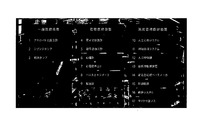
- the storage device 31 stores, for example, list data 311 including a list as illustrated in FIG. 2 in association with identification information.
- the example shown in FIG. 2 is a list including identification information regarding devices such as “1. Aneroid sphygmomanometer”, “2. Syringe pump”, “3. Infusion pump”, “4. Electronic thermometer”.
- FIG. 2 shows an example visually recognized by the user when the list data 311 is displayed with the glass 2. Therefore, it is a space where a user who can visually recognize the user through the lens of the glass 2 exists.
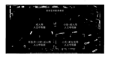
- the storage device 31 may store list data 311 including a list as shown in FIG. 3 in association with the identification information.
- the examples shown in FIG. 3 are “1. Adult ventilator”, “2. Pediatric / adult ventilator”, “3. Neonatal / pediatric / adult ventilator”, “4. It is a list
- the list data 311 illustrated in FIG. 3 is an example of data provided when the identification information “12. Ventilator” is selected in the list data 311 illustrated in FIG. 2.
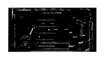
- the storage device 31 may store list data 311 including a list as shown in FIG. 4 in association with the identification information.
- the example shown in FIG. 4 is a list including identification information of ventilators manufactured by different companies.
- the list data 311 shown in FIG. 4 is an example of data provided when the identification information of “2. Respiratory for children / adults” is selected in the list data 311 shown in FIG.
- the presentation data 312 is data provided to the glass 2 by the information providing device 3.
- the storage device 31 stores a plurality of presentation data 312 associated with identification information.
- Each presentation data 312 includes, for example, image and audio data such as an operation description of the device.
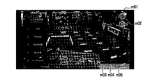
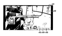
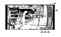
- the storage device 31 stores presentation data 312 including moving image data in which the images shown in FIGS. 5 to 7 are sequentially displayed in association with the identification information, for example.
- the presentation data 312 may include audio data that matches the moving image.
- the presentation data described with reference to FIGS. 5 to 7 is provided, for example, when any identification information is selected in the presentation data 312 shown in FIG.
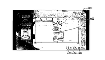
- the outline of the operation procedure of the artificial respiration circuit described in the presentation data 312 is shown.
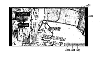
- one step of the operation procedure of the artificial respiration circuit is shown.
- the example shown in FIG. 7 includes information for asking the user who has operated according to the procedure shown in FIG. 6 whether or not the operation has been performed correctly. By making an inquiry in this way, an operation error or the like can be prevented.
- the mark m01 is a display for confirming whether or not the “AI mode” is being activated.
- the mark m02 is a display capable of confirming whether or not “help mode” to be described later is being activated.
- the marks m01 and m02 are displayed in different colors before and after the activation of each mode. Thereby, the user can easily confirm whether or not each mode is activated.
- the mark m03 is a temperature display section.
- the mark m04 is a humidity display unit.
- the mark m05 is an atmospheric pressure display unit. Each mark m03 to m05 displays a value measured by each sensor 27 to 29.
- the information displayed as the marks m01 to m05 is information acquired in the glass 2. Therefore, the presentation data 312 stored in the storage device 31 does not include such information. Therefore, the marks m01 to m05 may be added by the glass 2 when displaying on the display means 25.
- presentation data 312 can be data provided in the “help mode”.
- the storage device 31 can store, as the presentation data 312, data to be provided when confirmation of operation or attachment of the device is requested in the help mode.
- the data displayed in the help mode uses videos and the like. It can be a more detailed explanation.
- a user who cannot be understood only by the normal explanation can be provided with a more detailed explanation in the help mode.
- accurate assembly and operation method start to end can be visually confirmed by a continuous moving image.
- the determination data 313 is data used for determining whether the state of the equipment is correct or not in the “AI mode”. Specifically, the determination data 313 is image data of a pattern in an ideal state of the equipment. Further, the determination data 313 may include dangerous image data so that a fatal problem does not occur.
- the second receiving unit 301 receives data transmitted from the glass 2 via the network 4. Specifically, the second receiving unit 301 receives request data and image data.
- the extraction means 302 extracts list data and presentation data to be provided to the glass 2 from the storage device 31 according to the request data received by the second reception means 301. For example, when the identification information included in the request data specifies list data, the list data 311 identified by this identification information is extracted. Further, for example, when the identification information included in the request data specifies the presentation data, the presentation data 312 identified by the identification information is extracted.
- the determining unit 303 is used to determine whether the state of the equipment included in the image data received by the second receiving unit 301 from the storage device 31 is correct. Extract the judgment data to be used. The determination unit 303 determines whether the state of the equipment included in the received image data is correct.
- This determination unit 303 executes processing when the “AI mode” is activated in the glass 2. With the activation of the AI mode, the glass 2 executes acquisition of image data by the image acquisition unit 22 and transmission of image data by the first transmission unit 23. As a result, the determination unit 303 determines whether or not the equipment is correctly attached by using artificial intelligence. In this determination, the determination data 313 stored in the storage device 31 in advance and the image data acquired in the glass 2 are compared to determine the accuracy of equipment attachment or the like.
- the storage device 31 has a large number of images such as an accurate mounting method of the device and images of the shape of the device as the determination data 313 in advance.
- images such as an accurate mounting method of the device and images of the shape of the device as the determination data 313 in advance.
- the size and shape of the device included in the image and the image data received from the glass 2 are compared with the determination data 313 and the result is output. As a result, it is possible to determine whether or not dangerous attachment or the like is performed by using artificial intelligence, which can lead to medical safety.
- the second transmission means 304 transmits information to the glass 2 via the network 4. Specifically, the second transmission unit 304 transmits the list data and presentation data extracted by the extraction unit 302. The second transmission unit 304 transmits the result data determined by the determination unit 303.
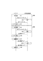
- the glass 2 acquires the voice of the user who requests the list data (S1). Moreover, the glass 2 transmits the request data specified by the voice acquired in step S1 to the information providing apparatus 3 (S2).
- the request data in step S2 includes identification information that identifies list data that the user requests to provide.
- the information providing device 3 extracts list data of identification information specified by the received request data (S3). Further, the information providing device 3 transmits the list data extracted in step 3 to the glass 2 (S4).
- Glass 2 displays the received list data (S5). Moreover, the glass 2 acquires the voice of the user who requests the presentation data selected from the list data (S6). Furthermore, the glass transmits the presentation data specified by the voice acquired in step S6 to the information providing apparatus 3 (S7).
- the request data in step S7 includes identification information that identifies presentation data that the user requests to provide.
- the information providing device 3 extracts the presentation data of the identification information specified by the received request data (S8). Moreover, the information provision apparatus 3 transmits the presentation data extracted by step S8 to the glass 2 (S9).
- Glass 2 displays the received presentation data (S10). The user performs work with reference to the information presented in the presentation data.
- the glass 2 acquires an image including a specific device, for example (S11). Further, the glass 2 transmits the image data acquired in step S11 to the information providing apparatus 3 (S12).
- the information providing apparatus 3 determines whether or not the operation of the equipment is appropriate using the image received from the glass 2 (S13). Moreover, the information provision apparatus 3 transmits the result data of step S13 to the glass 2 (S14).
- the glass 2 outputs the result received from the information providing device 3 (S15). For example, as shown in FIG. 9 or FIG. 10, result data is output.
- the series of processes (S100) for transmitting the list data in steps S1 to S5 and the series of processes (S200) for transmitting the presentation data in steps S6 to S10 may be repeated a plurality of times.
- the list data may be displayed continuously as described above with reference to FIGS. In such a case, the process of step S100 is repeated a plurality of times.
- a user who uses the information providing system 1 can check necessary operation procedures and the like with a minimum of hindrance to the user's business by hands-free.
- the glass 2 transmits a request signal to the information providing device 3 by acquiring sound.
- transmission of a request signal to the information providing apparatus 3 is not limited to this.
- the list data may be requested by operating an operation button or the like, but the request can be made hands-free by using voice. As a result, the request can be made without interrupting the operation that the user is currently performing.
- an acceleration switch that uses the movement of the user's head, a virtual switch that uses the movement of the user's body, an image switch that uses the movement of the user's eyes, a line-of-sight switch, or the like may be used. .
- a line-of-sight switch when a user views a predetermined icon or the like for a certain time or longer, processing corresponding to the icon is executed.
- the user performs work while wearing the glasses 2.
- the user may speak in a language different from the language used in the usage environment.
- the user wants to check the next information when wearing the glass 2
- if the user speaks “next” in English the user is requested to provide the next information.
- Request data can be transmitted.
- the request data requesting the provision of the previous information is sent To be able to.
- the display unit 25 may be able to switch the position where the presentation data is displayed.
- a plurality of presentation data itself may be provided, and the presentation data may be selectable according to the user's desire. For example, some users are better with more images, while others have more characters. Therefore, even if the description is for the same device, a plurality of types of presentation data with different amounts of images and characters may be prepared, and the user may select a desired type of presentation data. Thereby, in the information provision system 1, the presentation data of the type which a user can see more easily can be provided to a user.
- each unit of the information providing device 3 may be realized by software using a CPU and a memory, an integrated circuit (IC (Integrated Circuit) chip, LSI (Large Scale Integration)).
- IC Integrated Circuit
- LSI Large Scale Integration
- Etc. may be realized by a logic circuit (hardware) or a dedicated circuit.
- Each functional unit may be realized by one or a plurality of integrated circuits, and the functions of the plurality of functional units may be realized by a single integrated circuit.
- An LSI may be called a VLSI, a super LSI, an ultra LSI, or the like depending on the degree of integration.
- the circuit may be realized by a reconfigurable circuit (for example, FPGA: Field Programmable Gate Away).
- the information providing apparatus 3 is configured such that the CPU that executes instructions of the information providing program P, which is software that implements each function, the information providing program P, and various data are stored in a computer ( Alternatively, a ROM (Read Only Memory) or a storage device (referred to as “recording medium”) recorded in a readable manner by a CPU), a RAM (Random Access Memory) that develops the information providing program P, and the like are provided. And the objective of this invention is achieved when a computer (or CPU) reads the information provision program P from the said recording medium, and runs it.
- a computer or CPU
- a “non-temporary tangible medium” such as a tape, a disk, a card, a semiconductor memory, a programmable logic circuit, or the like can be used.
- the information providing program P may be supplied to the computer via any transmission medium (communication network, broadcast wave, etc.) capable of transmitting the information providing program P.
- the present invention can also be realized in the form of a data signal embedded in a carrier wave, in which the information providing program P is embodied by electronic transmission.
- the information providing program P can be implemented using, for example, a script language such as ActionScript or Javascript (registered trademark), an object-oriented programming language such as Objective-C or Java (registered trademark), or a markup language such as HTML5. .
- a script language such as ActionScript or Javascript (registered trademark)
- an object-oriented programming language such as Objective-C or Java (registered trademark)
- a markup language such as HTML5.
- Information provision system Glass 21
- Voice acquisition means 22
- Image acquisition means 23
- First transmission means 24
- First receiving means 25
- Display means 26
- Voice output means 3
- Information provision device 301
- Second receiving means 302
- Extraction means 303
- Second transmission means 31
- Storage device 311 List data
- 312 Presentation data 313 judgment data
Landscapes
- Engineering & Computer Science (AREA)
- Health & Medical Sciences (AREA)
- Theoretical Computer Science (AREA)
- Business, Economics & Management (AREA)
- General Health & Medical Sciences (AREA)
- Physics & Mathematics (AREA)
- General Engineering & Computer Science (AREA)
- General Physics & Mathematics (AREA)
- Biomedical Technology (AREA)
- Primary Health Care (AREA)
- Human Computer Interaction (AREA)
- Tourism & Hospitality (AREA)
- General Business, Economics & Management (AREA)
- Economics (AREA)
- Marketing (AREA)
- Human Resources & Organizations (AREA)
- Strategic Management (AREA)
- Child & Adolescent Psychology (AREA)
- Audiology, Speech & Language Pathology (AREA)
- Epidemiology (AREA)
- Medical Informatics (AREA)
- Public Health (AREA)
- User Interface Of Digital Computer (AREA)
- Medical Treatment And Welfare Office Work (AREA)
Applications Claiming Priority (2)
| Application Number | Priority Date | Filing Date | Title |
|---|---|---|---|
| JP2017025088A JP6607506B2 (ja) | 2017-02-14 | 2017-02-14 | 情報提供システム、情報提供装置、情報提供方法及び情報提供プログラム |
| JP2017-025088 | 2017-11-10 |
Publications (1)
| Publication Number | Publication Date |
|---|---|
| WO2018151174A1 true WO2018151174A1 (ja) | 2018-08-23 |
Family
ID=63170670
Family Applications (1)
| Application Number | Title | Priority Date | Filing Date |
|---|---|---|---|
| PCT/JP2018/005132 Ceased WO2018151174A1 (ja) | 2017-02-14 | 2018-02-14 | 情報提供システム、情報提供装置、情報提供方法及び情報提供プログラム |
Country Status (2)
| Country | Link |
|---|---|
| JP (1) | JP6607506B2 (enExample) |
| WO (1) | WO2018151174A1 (enExample) |
Families Citing this family (2)
| Publication number | Priority date | Publication date | Assignee | Title |
|---|---|---|---|---|
| JP2022098001A (ja) * | 2020-12-21 | 2022-07-01 | 国立大学法人滋賀医科大学 | 医療支援システム |
| JP7082384B1 (ja) | 2021-05-28 | 2022-06-08 | 浩平 田仲 | 学習システム及び学習方法 |
Citations (3)
| Publication number | Priority date | Publication date | Assignee | Title |
|---|---|---|---|---|
| JP2012007985A (ja) * | 2010-06-24 | 2012-01-12 | Nec Corp | 確認業務支援システム、サーバ装置、ヘッドマウントディスプレイ装置、ウェアラブル端末、確認業務支援方法およびプログラム |
| JP2014106698A (ja) * | 2012-11-27 | 2014-06-09 | Seiko Epson Corp | 表示装置、頭部装着型表示装置および表示装置の制御方法 |
| JP2016206433A (ja) * | 2015-04-23 | 2016-12-08 | 株式会社Nttドコモ | 情報処理装置、情報処理方法及びプログラム |
Family Cites Families (4)
| Publication number | Priority date | Publication date | Assignee | Title |
|---|---|---|---|---|
| JP3771892B2 (ja) * | 2002-10-28 | 2006-04-26 | 三菱重工業株式会社 | 危険情報伝達システム |
| JP2007172536A (ja) * | 2005-12-26 | 2007-07-05 | Nec Soft Ltd | 医療機器監視システム |
| EP2811459B1 (en) * | 2012-01-30 | 2020-02-19 | NEC Corporation | Information processing system, information processing method, information processing device, and control method and control program therefor, and communication terminal, and control method and control program therefor |
| JP2013200752A (ja) * | 2012-03-26 | 2013-10-03 | Terumo Corp | 医療機器の情報開示システム及び情報処理装置 |
-
2017
- 2017-02-14 JP JP2017025088A patent/JP6607506B2/ja active Active
-
2018
- 2018-02-14 WO PCT/JP2018/005132 patent/WO2018151174A1/ja not_active Ceased
Patent Citations (3)
| Publication number | Priority date | Publication date | Assignee | Title |
|---|---|---|---|---|
| JP2012007985A (ja) * | 2010-06-24 | 2012-01-12 | Nec Corp | 確認業務支援システム、サーバ装置、ヘッドマウントディスプレイ装置、ウェアラブル端末、確認業務支援方法およびプログラム |
| JP2014106698A (ja) * | 2012-11-27 | 2014-06-09 | Seiko Epson Corp | 表示装置、頭部装着型表示装置および表示装置の制御方法 |
| JP2016206433A (ja) * | 2015-04-23 | 2016-12-08 | 株式会社Nttドコモ | 情報処理装置、情報処理方法及びプログラム |
Also Published As
| Publication number | Publication date |
|---|---|
| JP2018132889A (ja) | 2018-08-23 |
| JP6607506B2 (ja) | 2019-11-20 |
Similar Documents
| Publication | Publication Date | Title |
|---|---|---|
| US9645785B1 (en) | Heads-up displays for augmented reality network in a medical environment | |
| JP6252004B2 (ja) | 情報処理装置、情報処理方法、および、情報処理システム | |
| US10904653B2 (en) | Microphone natural speech capture voice dictation system and method | |
| US11372618B2 (en) | Intercom system for multiple users | |
| US8686851B2 (en) | System and method for rapid location of an alarm condition | |
| US10152150B2 (en) | Facilitating user input via arm-mounted peripheral device interfacing with head-mounted display device | |
| US10755222B2 (en) | Work management apparatus, work defect prevention program, and work defect prevention method | |
| TW201505603A (zh) | 資訊處理裝置、資訊處理方法及資訊處理系統 | |
| US20220392361A1 (en) | Learning system and learning method | |
| KR20170109297A (ko) | 전방위 영상을 제공하는 전자 장치 및 방법 | |
| KR20160017593A (ko) | 글라스형 웨어러블 디바이스를 이용한 탈출경로 제공방법 및 프로그램 | |
| JP6607506B2 (ja) | 情報提供システム、情報提供装置、情報提供方法及び情報提供プログラム | |
| CN111722401A (zh) | 显示装置、显示控制方法以及显示系统 | |
| KR20170063275A (ko) | 웨어러블 기기를 이용한 환자 관리 시스템 및 방법 | |
| US20150278178A1 (en) | Information integration apparatus, information integration system and non-transitory computer readable recording medium | |
| WO2023158800A1 (en) | Intelligent surgical display system and method | |
| WO2019021566A1 (ja) | 情報処理装置、情報処理方法、及びプログラム | |
| US20220008161A1 (en) | Information processing device, presentation method, and surgical system | |
| KR101790755B1 (ko) | 사용자 기기 연동을 통한 경로 안내 서비스 제공 방법 및 스마트 글라스 | |
| WO2017187496A1 (ja) | 救急撮像画像共有システム、救急撮像画像共有方法、および救急撮像画像共有プログラム | |
| KR20200021671A (ko) | 환자 통합 관리 시스템 | |
| US11413111B2 (en) | Augmented reality system for medical procedures | |
| KR20240133988A (ko) | 규칙 기반 개입을 통한 의료 결정 지원 시스템 | |
| US12009097B2 (en) | Wireless communication system for remote medical assistance | |
| US20160062481A1 (en) | Electronic equipment displaying various kinds of information available by wearing on body |
Legal Events
| Date | Code | Title | Description |
|---|---|---|---|
| 121 | Ep: the epo has been informed by wipo that ep was designated in this application |
Ref document number: 18754404 Country of ref document: EP Kind code of ref document: A1 |
|
| NENP | Non-entry into the national phase |
Ref country code: DE |
|
| 122 | Ep: pct application non-entry in european phase |
Ref document number: 18754404 Country of ref document: EP Kind code of ref document: A1 |