WO2018150631A1 - Dispositif de détermination, procédé de détermination, et programme - Google Patents
Dispositif de détermination, procédé de détermination, et programme Download PDFInfo
- Publication number
- WO2018150631A1 WO2018150631A1 PCT/JP2017/037821 JP2017037821W WO2018150631A1 WO 2018150631 A1 WO2018150631 A1 WO 2018150631A1 JP 2017037821 W JP2017037821 W JP 2017037821W WO 2018150631 A1 WO2018150631 A1 WO 2018150631A1
- Authority
- WO
- WIPO (PCT)
- Prior art keywords
- determination
- maintenance
- state value
- state
- storage system
- Prior art date
Links
Images


Classifications
-
- G—PHYSICS
- G01—MEASURING; TESTING
- G01R—MEASURING ELECTRIC VARIABLES; MEASURING MAGNETIC VARIABLES
- G01R31/00—Arrangements for testing electric properties; Arrangements for locating electric faults; Arrangements for electrical testing characterised by what is being tested not provided for elsewhere
- G01R31/36—Arrangements for testing, measuring or monitoring the electrical condition of accumulators or electric batteries, e.g. capacity or state of charge [SoC]
- G01R31/392—Determining battery ageing or deterioration, e.g. state of health
-
- G—PHYSICS
- G01—MEASURING; TESTING
- G01R—MEASURING ELECTRIC VARIABLES; MEASURING MAGNETIC VARIABLES
- G01R31/00—Arrangements for testing electric properties; Arrangements for locating electric faults; Arrangements for electrical testing characterised by what is being tested not provided for elsewhere
- G01R31/36—Arrangements for testing, measuring or monitoring the electrical condition of accumulators or electric batteries, e.g. capacity or state of charge [SoC]
- G01R31/367—Software therefor, e.g. for battery testing using modelling or look-up tables
-
- G—PHYSICS
- G01—MEASURING; TESTING
- G01R—MEASURING ELECTRIC VARIABLES; MEASURING MAGNETIC VARIABLES
- G01R31/00—Arrangements for testing electric properties; Arrangements for locating electric faults; Arrangements for electrical testing characterised by what is being tested not provided for elsewhere
- G01R31/36—Arrangements for testing, measuring or monitoring the electrical condition of accumulators or electric batteries, e.g. capacity or state of charge [SoC]
- G01R31/374—Arrangements for testing, measuring or monitoring the electrical condition of accumulators or electric batteries, e.g. capacity or state of charge [SoC] with means for correcting the measurement for temperature or ageing
-
- G—PHYSICS
- G01—MEASURING; TESTING
- G01R—MEASURING ELECTRIC VARIABLES; MEASURING MAGNETIC VARIABLES
- G01R31/00—Arrangements for testing electric properties; Arrangements for locating electric faults; Arrangements for electrical testing characterised by what is being tested not provided for elsewhere
- G01R31/36—Arrangements for testing, measuring or monitoring the electrical condition of accumulators or electric batteries, e.g. capacity or state of charge [SoC]
- G01R31/382—Arrangements for monitoring battery or accumulator variables, e.g. SoC
- G01R31/3835—Arrangements for monitoring battery or accumulator variables, e.g. SoC involving only voltage measurements
-
- G—PHYSICS
- G01—MEASURING; TESTING
- G01R—MEASURING ELECTRIC VARIABLES; MEASURING MAGNETIC VARIABLES
- G01R31/00—Arrangements for testing electric properties; Arrangements for locating electric faults; Arrangements for electrical testing characterised by what is being tested not provided for elsewhere
- G01R31/36—Arrangements for testing, measuring or monitoring the electrical condition of accumulators or electric batteries, e.g. capacity or state of charge [SoC]
- G01R31/385—Arrangements for measuring battery or accumulator variables
-
- H—ELECTRICITY
- H01—ELECTRIC ELEMENTS
- H01M—PROCESSES OR MEANS, e.g. BATTERIES, FOR THE DIRECT CONVERSION OF CHEMICAL ENERGY INTO ELECTRICAL ENERGY
- H01M10/00—Secondary cells; Manufacture thereof
- H01M10/42—Methods or arrangements for servicing or maintenance of secondary cells or secondary half-cells
- H01M10/48—Accumulators combined with arrangements for measuring, testing or indicating the condition of cells, e.g. the level or density of the electrolyte
- H01M10/486—Accumulators combined with arrangements for measuring, testing or indicating the condition of cells, e.g. the level or density of the electrolyte for measuring temperature
-
- G—PHYSICS
- G01—MEASURING; TESTING
- G01R—MEASURING ELECTRIC VARIABLES; MEASURING MAGNETIC VARIABLES
- G01R31/00—Arrangements for testing electric properties; Arrangements for locating electric faults; Arrangements for electrical testing characterised by what is being tested not provided for elsewhere
- G01R31/36—Arrangements for testing, measuring or monitoring the electrical condition of accumulators or electric batteries, e.g. capacity or state of charge [SoC]
- G01R31/3644—Constructional arrangements
- G01R31/3648—Constructional arrangements comprising digital calculation means, e.g. for performing an algorithm
-
- H—ELECTRICITY
- H01—ELECTRIC ELEMENTS
- H01M—PROCESSES OR MEANS, e.g. BATTERIES, FOR THE DIRECT CONVERSION OF CHEMICAL ENERGY INTO ELECTRICAL ENERGY
- H01M10/00—Secondary cells; Manufacture thereof
- H01M10/42—Methods or arrangements for servicing or maintenance of secondary cells or secondary half-cells
- H01M10/425—Structural combination with electronic components, e.g. electronic circuits integrated to the outside of the casing
- H01M2010/4278—Systems for data transfer from batteries, e.g. transfer of battery parameters to a controller, data transferred between battery controller and main controller
-
- Y—GENERAL TAGGING OF NEW TECHNOLOGICAL DEVELOPMENTS; GENERAL TAGGING OF CROSS-SECTIONAL TECHNOLOGIES SPANNING OVER SEVERAL SECTIONS OF THE IPC; TECHNICAL SUBJECTS COVERED BY FORMER USPC CROSS-REFERENCE ART COLLECTIONS [XRACs] AND DIGESTS
- Y02—TECHNOLOGIES OR APPLICATIONS FOR MITIGATION OR ADAPTATION AGAINST CLIMATE CHANGE
- Y02E—REDUCTION OF GREENHOUSE GAS [GHG] EMISSIONS, RELATED TO ENERGY GENERATION, TRANSMISSION OR DISTRIBUTION
- Y02E60/00—Enabling technologies; Technologies with a potential or indirect contribution to GHG emissions mitigation
- Y02E60/10—Energy storage using batteries
Definitions
- the present invention relates to a determination device, a determination method, and a program.
- Patent Documents 1 to 3 disclose techniques related to the present invention.
- Patent Document 1 discloses a storage battery inspection device that inspects the state of a storage battery pack that is attached to a predetermined device and can supply power to the predetermined device.
- the storage battery pack includes a holding unit that holds history information related to the operation of the storage battery pack, and a communication terminal for performing communication with a predetermined device.
- the storage battery inspection device is portable and can be connected to a communication terminal of a storage battery pack removed from a predetermined device, information on the operation of the storage battery pack, and a state indicating a correspondence between the state of the storage battery pack
- the storage unit storing the table, the history information held in the holding unit through the connection unit, and the acquired history information is collated with the information on the operation of the storage battery pack in the state table, thereby
- the determination part which determines the state of this, and the presentation part which presents the result of determination are provided.
- Patent Document 2 discloses a maintenance work management apparatus that manages maintenance work of an image forming apparatus by maintenance personnel.
- the maintenance work management device consists of a maintenance worker certificate creation unit that creates a maintenance worker certificate in which maintenance personnel information including personal information of maintenance personnel is encrypted with a secret key, and maintenance that outputs the maintenance worker certificate to the image forming device. And a member certificate output unit.
- the image forming apparatus includes a maintenance worker certificate input unit that inputs a maintenance worker certificate from a maintenance work management device, an ID card reading unit that reads personal information of the maintenance worker from an ID card carried by the maintenance worker, and a maintenance worker.
- a maintenance engineer authentication unit that permits a transition to a maintenance mode in which maintenance work can be performed when the personal information of the maintenance engineer information obtained by decrypting the certificate with the public key matches the personal information of the ID card .
- Patent Document 3 discloses a maintenance management method. If the current installation location information of the target device is the same as or different from the installation location at the time of the contract, the maintenance management method includes a step of registering the target device for periodic inspection; and For maintenance personnel identified based on the received maintenance personnel information, refer to the qualification database to determine if the maintenance qualification of the maintenance target device is possessed and the current position matches the installation location of the maintenance target device The maintenance work start time, maintenance work end time, maintenance work end time of the maintenance target device when the maintenance work information is received from the portable terminal. Registering the maintenance work information in the third table.
- the power storage system needs regular maintenance.
- the presence or absence of maintenance affects the probability of failure occurrence.
- the stakeholder of the power storage system is required to confirm whether or not maintenance is performed.
- interested parties include, but are not limited to, insurance companies that provide insurance products that compensate for failure of the power storage system.
- the presence or absence of maintenance can be confirmed by, for example, a report from the operator of the power storage system, but there is a problem that it cannot be confirmed whether or not appropriate maintenance is actually being performed.
- An object of the present invention is to provide a determination device, a determination method, and a program that solve the above-described problems.
- a determination unit that determines whether or not maintenance of the power storage system is performed based on a time change of the state value,
- a program is provided that functions as:
- the determination apparatus includes means for acquiring a state value indicating the state of the power storage system, and means for determining whether or not maintenance of the power storage system is performed based on a time change of the state value.
- the state of the electricity storage system gradually deteriorates due to deterioration over time.
- the state of the power storage system is improved by performing maintenance.
- the time change in the state value indicating the state of the power storage system represents such a change in the state of the power storage system. For this reason, it is possible to determine whether or not the maintenance of the power storage system is performed based on the time change of the state value.
- the determination apparatus of the present embodiment it is possible to determine whether or not maintenance of the power storage system is performed based on objective data such as “time change of the state value indicating the state of the power storage system”. According to such a determination apparatus of the present embodiment, a highly reliable determination result can be provided.
- Each functional unit included in the determination apparatus includes a CPU (Central Processing Unit) of an arbitrary computer, a memory, a program loaded into the memory, a storage unit such as a hard disk storing the program (stage of shipping the device in advance)
- a storage unit such as a hard disk storing the program (stage of shipping the device in advance)
- programs downloaded from storage media such as CDs (Compact Discs) and servers on the Internet can also be stored.) Realized by combination. It will be understood by those skilled in the art that there are various modifications to the implementation method and apparatus.
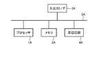
- FIG. 1 is a block diagram illustrating a hardware configuration of the determination apparatus according to this embodiment.
- the determination apparatus includes a processor 1A, a memory 2A, an input / output interface 3A, a peripheral circuit 4A, and a bus 5A.
- the peripheral circuit 4A includes various modules.
- the bus 5A is a data transmission path through which the processor 1A, the memory 2A, the peripheral circuit 4A, and the input / output interface 3A transmit / receive data to / from each other.
- the processor 1A is an arithmetic processing device such as a CPU (Central Processing Unit) or a GPU (Graphics Processing Unit).
- the memory 2A is a memory such as a RAM (Random Access Memory) or a ROM (Read Only Memory).
- the input / output interface 3A is an interface for acquiring information from an input device (eg, keyboard, mouse, microphone, physical key, touch panel display, code reader, etc.), external device, external server, external sensor, etc., and an output device ( Examples: display, speaker, printer, mailer, etc.), external device, an interface for outputting information to an external server, etc.
- the processor 1A can issue a command to each module and perform a calculation based on the calculation result.
- FIG. 2 an example of the functional block diagram of the determination apparatus 10 is shown.
- the determination apparatus 10 includes a determination unit 11 and an acquisition unit 12.
- FIG. 7 shows another example of a functional block diagram of the determination apparatus 10.
- the determination device 10 may include a determination unit 11, an acquisition unit 12, and an output unit 13.
- the acquisition unit 12 acquires a state value indicating the state of the power storage system.
- the determination unit 11 determines whether or not maintenance of the power storage system is performed based on a temporal change in a state value indicating the state of the power storage system.
- Maintenance includes battery replacement (e.g., replacement of all batteries, replacement of parts (modules, cells, etc.), addition of battery stack, cleaning of terminals (e.g., removal of dirt such as carbon), cooling device ( Examples include, but are not limited to, cleaning and replacement of fins and the like, cleaning of intake and exhaust ports, cleaning and replacement of switching elements, replacement of bus bars, and the like.
- the type of status value depends on the maintenance subject to judgment.
- the state value may be, for example, the capacity [kWh] or the output [kW] of the battery of the power storage system.
- the battery capacity of the power storage system decreases with time, but improves (increases) as the battery is replaced.
- the state value may be, for example, a change value (change rate or change amount) of the capacity of the battery with respect to a temperature change. It is known that the battery capacity decreases as the battery temperature decreases, and the battery capacity increases as the battery temperature increases. And if a battery deteriorates, the change of the capacity
- the state value is, for example, the SOC (state ⁇ ⁇ ⁇ ⁇ ⁇ of charge) of the battery: X [%] (X is greater than 0 and less than 100) [kWh ].
- the amount of power [kWh] per SOC: X [%] of the battery decreases with time, but improves (increases) as the battery is replaced.
- the state value may be, for example, a voltage range used for charging and discharging.
- the voltage range used for charging / discharging increases with time. However, when a module or cell that deteriorates quickly is replaced selectively or the entire battery is replaced, the voltage range is improved (decreased) accordingly.
- the state value is, for example, the rate of temperature change per unit time of the power storage system per charge / discharge of the power storage system: Y [kW] (Y is greater than 0) It may be.
- Charge / discharge of power storage system The rate of temperature change per unit time of the power storage system per Y [kW] (Y is greater than 0) increases with time, but improves (decreases) with battery replacement. .
- the state value may be, for example, an insulation resistance of the power storage system. Since the battery is direct current, there is always a potential. For this reason, dirt such as carbon tends to adhere to the terminal portion. As the time passes, the dirt attached to the terminal portion increases and the insulation resistance decreases, but improves (increases) as the terminal portion is cleaned.
- the state value may be, for example, a temperature difference between the temperature of the storage battery system and the outside air temperature.
- the temperature rise of the power storage system increases.
- the dust attached to the cooling device increases with time, and the temperature difference between the temperature of the storage battery system and the outside air temperature increases, but improves (decreases) as the cooling device is cleaned.
- the state value may be, for example, a temperature difference between the temperature of the storage battery system and the outside air temperature. Since the power storage system is a stationary device and has been installed at the same place for a long time, plants can grow in the vicinity and insects can nest. If the intake / exhaust port is blocked due to this, the intake / exhaust performance deteriorates and the temperature rise of the power storage system increases. The amount of the intake / exhaust port that is blocked over time increases, and the temperature difference between the storage battery system temperature and the outside air temperature increases, but improves (decreases) as the cooling device is cleaned.
- the state value is, for example, the degree of deviation from the target value [kW] of the output [kW] of the power storage system It may be.
- the power storage system may perform an output operation with a given target value.
- the state value is, for example, from the target value [kW] of the output [kW] of the power storage system
- the degree of deviation may be used.
- the power storage system may perform an output operation with a given target value.
- the performance of the switching element of the PCS or the cooling device deteriorates due to aging or the like, the temperature of the power storage system gradually rises, and the degree of the deviation increases. In some cases, the operation of the power storage system may stop. However, it is improved if the cooling device (fin or the like) is cleaned or replaced, or the switching element is cleaned or replaced (the degree of divergence is reduced).
- the state value may be a measured value measured by any means.
- the state value may be a value measured by the power storage system, or may be a value measured by an external device different from the power storage system.
- the determination device 10 can communicate with these devices by any means, and can acquire a state value (measured value) from these devices.
- the determination unit 11 can determine that the maintenance has been performed when the time change of the state value changes from the trend so far.
- the trend of the state value over time increases with time or decreases with time.
- the determination unit 11 may determine that the maintenance has been performed when detecting a change from the previous trend in which the state value decreases with time.
- FIG. 3 shows an example of the time change of the state value.
- the trend is such that the state value decreases with time.
- the capacity of the battery of the power storage system shows such a trend.
- the determination unit 11 acquires the state value at the timing of B, the determination unit 11 determines that the time change of the state value has changed from the previous trend.
- the determination unit 11 may determine that the trend has changed when the state value M1 increases from the previous value M0 (M1> M0). In addition, the determination unit 11 may determine that the trend has changed when the state value M1 increases from the previous value M0 by a predetermined level or more (predetermined value or more, a predetermined ratio or more) (M1 ⁇ M0 ⁇ T1> 0). Good. In addition, the determination unit 11 maintains the level after the state value M1 has increased from the previous value M0 (or has increased by a predetermined level or more) and the subsequent predetermined number of state values M2 to Mn have increased. In this case, it may be determined that the trend has changed.
- the method for determining whether or not the above level is maintained is a design matter. For example, if the difference between M1 and each of M2 to Mn is smaller than the difference between M0 and each of M2 to Mn, M2 It may be determined that each of Mn to Mn maintains the increased level. In a situation where periodically detected state values are gradually decreasing in time series (temporally), if the state value increases from the previous value, it is determined that maintenance has been performed because the trend has changed.
- the determination unit 11 may determine that the maintenance has been performed when detecting a change from the previous trend in which the state value increases with time. For example, in a charging system that is charged regularly, the charge / discharge voltage range in the case of consuming a certain amount of power from a fully charged state shows such a trend. In the example of detecting a change from an increasing trend, the determination unit 11 may determine that the trend has changed when the state value M1 decreases from the previous value M0 (M0> M1). In addition, the determination unit 11 may determine that the trend has changed when the state value M1 decreases from the previous value M0 by a predetermined level or more (predetermined value or more, a predetermined ratio or more) (M0 ⁇ M1 ⁇ T2> 0). Good.
- the determination unit 11 maintains the level after the state value M1 decreases from the previous value M0 (or decreases by a predetermined level or more) and the subsequent predetermined number of state values M2 to Mn decrease. In this case, it may be determined that the trend has changed.
- the method for determining whether or not the above level is maintained is a design matter. For example, if the difference between M1 and each of M2 to Mn is smaller than the difference between M0 and each of M2 to Mn, M2 It may be determined that each of Mn to Mn maintains the level after the decrease. In a situation where periodically detected state values are gradually increasing in time series (temporally), if the state value decreases from the previous value, it is determined that maintenance has been performed because the trend has changed.
- the determination unit 11 may detect a trend of time change of each state value based on the acquired state value.
- the trend of the time change of the state value (the trend of the change of the state value according to aging deterioration) is known in advance.
- information indicating the content of the trend for each type of state value (hereinafter, sometimes referred to as “trend information”) may be stored in advance in the storage unit of the determination apparatus 10.
- the acquisition part 12 (refer FIG. 7) of the determination apparatus 10 may acquire trend information from the said memory
- the determination part 11 may grasp
- the trend information may be stored in an external device or a power storage system different from the determination device 10.
- the acquisition part 12 may communicate by a communication means arbitrarily and may acquire trend information from the said external device or an electrical storage system.
- acquisition means that the device itself obtains data or information stored in another device or storage medium (active acquisition), for example, receives a request or inquiry from another device.
- active acquisition To access and read other devices and storage media, and to input data or information output from other devices (passive acquisition), for example, distribution (or transmission) Receiving data or information to be transmitted), and the like. It also includes selecting and acquiring from received data or information, or selecting and receiving distributed data or information.
- the acquisition unit 12 may acquire a plurality of types of state values.
- the determination part 11 may determine the change of the trend of each of multiple types of state values, and may determine the presence or absence of each of multiple types of maintenance based on the result.
- the determination unit 11 may specify which maintenance has been performed from the change in the trend of a plurality of types of state values. For example, information for identifying the performed maintenance may be associated in advance for each combination of state values whose trend has changed (one state value or a combination of a plurality of state values). Then, the determination unit 11 performs the maintenance performed based on the determination result of the trend change of each state value and the corresponding information indicating which maintenance is performed from the trend change of the plurality of types of state values. You may specify.
- the determination unit 11 may determine that the battery has been replaced or that the terminal has been cleaned. In addition, when the trend of the PCSDC voltage and the battery voltage changes, the determination unit 11 may determine that the battery connector has been replaced. In addition, the determination part 11 may determine with the battery cooling device having been cleaned when the trend of battery temperature and the pressure in a housing
- the acquisition unit 12 may acquire one type of state value.
- the determination part 11 may determine the change of the trend of the said state value, and may determine the presence or absence of one type of maintenance based on the result.
- the acquisition unit 12 may periodically acquire the state value at a predetermined time interval T1. Then, each time the acquisition unit 12 acquires the state value or at a time interval longer than the time interval T1, the determination unit 11 is based on the state value accumulated so far and the newly acquired state value. The presence or absence of a trend change may be determined. That is, the determination unit 11 may determine whether or not there is a trend change periodically at the time interval T1 or periodically at a time interval longer than the time interval T1. Examples of the time interval T1 include, but are not limited to, one day, one week, one month, several months, and one year. When acquiring a plurality of types of state values, the state values may be acquired at different time intervals T1 for each state value type, and the determination may be made at different time intervals.
- the acquisition unit 12 may acquire a plurality of state values at a predetermined time interval T1 within a predetermined determination period T2 including a predetermined maintenance execution timing.
- the acquisition unit 12 may acquire a plurality of state values at a predetermined time interval T1 within the determination period T2.
- the acquisition unit 12 may not acquire the state value in a period other than the determination period T2.
- the determination part 11 may determine whether the time change of the state value in the determination period T2 has changed from the trend of the time change of the state value before the determination period T2.
- the trend of the time change of the state value before the determination period T2 is specified based on the type of the state value.
- the determination period T2 may be from February 3, 2017 to February 11. That is, it may be determined whether or not there is a change in the state value over time from February 3, 2017 to February 11, 2017.
- the determination period T2 is merely an example, and the present invention is not limited to this.
- Examples of the time interval T1 in the example include 15 minutes, 30 minutes, 1 hour, and 1 day, but are not limited thereto.
- Timing 3 In the timing example 2, the maintenance execution timing is determined in advance, but in the timing example 3, the maintenance execution timing is variable. In this case, when the maintenance schedule is determined, an arbitrary user (for example, a maintenance person) inputs maintenance information including the scheduled maintenance execution timing to the determination apparatus 10 by an arbitrary means.
- the acquisition unit 12 may acquire a plurality of state values at a predetermined time interval T1 within a predetermined determination period T2 including the scheduled maintenance execution time indicated by the maintenance information.
- the acquisition unit 12 may acquire a plurality of state values at a predetermined time interval T1 within the determination period T2.
- the acquisition unit 12 may not acquire the state value in a period other than the determination period T2.
- the determination part 11 may determine whether the time change of the state value in the determination period T2 has changed from the trend of the time change of the state value before the determination period T2.
- the trend of the time change of the state value before the determination period T2 is specified based on the type of the state value. For example, when the scheduled maintenance execution timing is February 7, 2017, the determination period T2 may be from February 3, 2017 to February 11, 2017.
- the said determination period is an example to the last, and is not limited to this.
- the time interval T1 in this example is, for example, 15 minutes, 30 minutes, 1 hour, 1 day, etc., but is not limited thereto.
- the predetermined storage device may be a storage device installed in a center that manages the plurality of power storage systems 3, or may be a storage device installed locally corresponding to each of the plurality of power storage systems 3. Others may also be used. Then, the acquisition unit 12 acquires a predetermined state value from the state values accumulated in the storage device. Examples of the time interval T3 include 15 minutes, 30 minutes, 1 hour, and 1 day, but are not limited thereto.
- the acquisition unit 12 receives notification (maintenance information) indicating the start and / or end of maintenance by any means.
- notification maintenance information
- the notification maintenance information which shows the start and / or completion
- the acquisition unit 12 may acquire a plurality of state values at a predetermined time interval T1 within a predetermined determination period T2 including a maintenance start timing and / or an end timing from the storage device.
- the acquisition unit 12 may acquire a plurality of state values at a predetermined time interval T1 within the determination period T2.
- the acquisition part 12 does not need to acquire the state value of periods other than the determination period T2.
- the determination part 11 may determine whether the time change of the state value in the determination period T2 has changed from the trend of the time change of the state value before the determination period T2.
- the trend of the time change of the state value before the determination period T2 is specified based on the type of the state value.
- the determination period T2 is set to February 2017. It may be from 0:00 on the 6th to 20:00 on the 7th of February.
- the time interval T1 in this example is, for example, 15 minutes, 30 minutes, 1 hour, 1 day, etc., but is not limited thereto.
- the time interval T1 and the time interval T3 may be the same value or different values.
- the acquisition unit 12 may acquire the state value accumulated in the storage device from the storage device.
- Timing example 5" In this example, the acquisition of the state value by the acquisition unit 12 and the determination by the determination unit 11 are performed at two or more timings in the timing examples 1 to 4.
- the maintenance information in the timing examples 3 and 4 may include time information such as a maintenance execution schedule, a start / end timing, and a completed time.
- the determination part 11 may perform the presence or absence determination of a maintenance from the change of the trend of the state which the acquisition part 12 acquired in the timing and time corresponding to the said time information.
- determination may be made by acquiring the state value from the power storage system at the relevant time in real time, and later obtaining the state value at that time from the storage device, not only externally or internally. You can judge.
- determination may be made by acquiring a state value at the time from a storage device, not limited to the outside or the inside.
- the acquisition unit 12 waits for a new state value until a new state value is acquired (No in S10).
- the determination unit 11 determines whether the temporal change in the state value has changed from the previous trend (S11). The details of the determination process by the determination unit 11 are as described above.
- the output unit 13 (see FIG. 8) outputs the presence / absence of maintenance.
- the output unit 13 when it is determined that the time change of the state value has changed from the trend so far, the output unit 13 outputs that the maintenance has been performed.
- the output unit 13 outputs that maintenance has not been performed.
- the output unit 13 may output the determination result by the determination unit 11 to the determination device or to an external device.
- the output unit 13 may output information indicating whether or not maintenance is performed toward the determination device 10 or the storage device of the external device. Information indicating whether or not maintenance is performed may be stored in the storage device. Further, the output unit 13 may transmit information indicating whether or not maintenance is performed using an e-mail address registered in advance as a transmission destination.
- the determination apparatus 10 of the present embodiment described above it is possible to determine whether or not maintenance of the power storage system is performed based on objective data “time change of the state value indicating the state of the power storage system”. According to such a determination apparatus 10 of the present embodiment, a highly reliable determination result can be provided.
- non-maintenance of maintenance can be a disclaimer.
- the determination apparatus 10 of the present embodiment it is possible to provide useful information to an insurance company that provides the insurance product.
- the performed maintenance can be identified from the type of state value whose trend has changed.
- the determination device 10 of the present embodiment has a function of determining whether maintenance is performed so as to satisfy a predetermined timing condition. And different.
- An example of the hardware configuration of the determination apparatus 10 of the present embodiment is the same as that of the first embodiment, and thus description thereof is omitted here.
- FIG. 2 or FIG. 7 An example of a functional block diagram of the determination apparatus 10 of the present embodiment is shown in FIG. 2 or FIG. 7 as in the first embodiment.
- the configuration of the acquisition unit 12 is the same as that of the first embodiment.
- the determination unit 11 and the output unit 13 have functions described below in addition to or instead of the functions described in the first embodiment.
- the determination part 11 can determine the presence or absence of the maintenance of an electrical storage system similarly to 1st Embodiment. Note that the determination result of the determination unit 11 may be associated with information indicating the determination date.
- the determination part 11 determines whether the maintenance is performed so that the predetermined temporal condition may be satisfied based on the determination result of the presence or absence of the maintenance of the power storage system.
- the acquisition of the state value by the acquisition unit 12 and the determination by the determination unit 11 may be performed at any one or more of the timing examples 1 to 5 described in the first embodiment.
- the determination unit 11 determines whether or not the maintenance operation satisfies the timing condition (e.g., once a month, once a year, once every three years, etc.). Also good.
- the acquisition unit 12 may periodically acquire the state value at a predetermined time interval T1.
- the determination unit 11 is a state in which the power storage system needs maintenance every time the acquisition unit 12 acquires a state value or based on a newly acquired state value at a time interval longer than the time interval T1. It may be determined whether or not. And when the determination part 11 determines with the state which requires a maintenance, you may determine whether the maintenance is performed so that it may satisfy within predetermined period T4 (temporal conditions) after determining.
- the acquisition unit 12 may acquire a plurality of state values at a predetermined time interval T1 ′ within a predetermined determination period T2 after it is determined that the state requires maintenance.
- the acquisition unit 12 may acquire a plurality of state values at a predetermined time interval T1 within the determination period T2.
- the determination part 11 may determine whether the time change of the state value in the determination period T2 has changed from the trend of the time change of the state value before the determination period T2.
- the trend of the time change of the state value before the determination period T2 is specified based on the type of the state value.
- T2 ⁇ T4. That is, the determination period T2 includes a predetermined period T4 indicated by the above time condition. Further, T1> T1 ′. That is, the acquisition unit 12 decreases the time interval for acquiring the state value in the determination period T2 as compared with the other periods. Examples of the time interval T1 in the example include 1 hour, 1 day, and the like, but are not limited thereto. Examples of the time interval T1 ′ in the example include 15 minutes, 30 minutes, 1 hour, and the like, but are not limited thereto.
- the output unit 13 may request the user to perform maintenance within the predetermined period T4.
- the request to the user may be realized by sending an e-mail to a destination registered in advance, or by an output via a power storage system, the determination device 10 or a display, warning lamp, speaker, or the like included in these devices. It may be realized.
- the determination unit 11 may set the predetermined period T4 according to the difference between the newly acquired state value and the reference value.
- the output part 13 may request
- the acquisition unit 12 may change the time interval T1 based on the difference between the state value and the reference value. Specifically, the acquisition unit 12 may decrease the time interval T1 as the difference between the state value and the reference value becomes smaller (as the state value approaches the reference value).
- the determination unit 11 may change the time interval for determining whether the state requires maintenance based on the difference between the state value and the reference value. Good. Specifically, the determination unit 11 may decrease the time interval as the difference between the state value and the reference value becomes smaller (as the state value approaches the reference value).
- the determination unit 11 may determine that the state corresponding to the state value requires maintenance. On the other hand, while the reference value is exceeded, it may be determined that no maintenance corresponding to the state value is required.
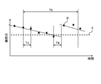
- FIG. 8 shows an example of the state value indicating the trend over time and the reference value.
- the trend is such that the state value decreases with time.
- the state value at the timing of C is lower than the reference value X.
- the determination unit 11 determines that a state requiring maintenance is obtained when the state value of the timing of C is acquired. And when the state value before that shown in the figure is acquired, it is determined that the state does not require maintenance. As described above, there is a change between the state value at the timing B and the state value at the timing C immediately before it from the decreasing trend. In the case of this example, when the determination unit 11 acquires the state value at the timing B, the determination unit 11 determines that the temporal change in the state value has changed from the previous trend, that is, that maintenance has been performed.
- the determination unit 11 may determine that the state corresponding to the state value requires maintenance. On the other hand, while it is below the reference value, it may be determined that no maintenance corresponding to the state value is required.
- the acquisition unit 12 acquires the state value at a time interval T1 that is shorter than the time interval T5 of maintenance that should be periodically performed. Then, the determination unit 11 determines the necessity of maintenance at, for example, the time interval T1 or a time interval longer than the time interval T1 (shorter than T5). The necessity of maintenance can be performed by comparing the state value with the reference value as described above. If the determination unit 11 determines that maintenance is required, then it is necessary to perform maintenance within a predetermined period T4. The predetermined period T4 may be determined in advance for each type of maintenance. Further, it may be determined according to the magnitude of the difference between the state value and the reference value. Then, the output unit 13 outputs a maintenance request within the predetermined period T4 to the user. Within the predetermined period T4, the acquisition unit 12 acquires the state value at a time interval T1 ′ shorter than the time interval T1.
- T5 is, for example, one year.
- T1 is, for example, one month.
- T4 is, for example, two weeks, one month, or two months.
- T1 ′ is, for example, 15 minutes, 30 minutes, 1 hour, or 1 day.
- illustration of the value of T1, T1 ', T4, and T5 here is an example to the last, and is not limited to this.
- the predetermined period T4 may be one fixed value given for each type of maintenance, or may be a variable value that changes according to the state value.
- variable values include those determined according to the degree of deviation between the state value and the reference value, for example.
- the predetermined period T4 is given according to the degree of deviation of the state value below the reference value from the reference value.
- the predetermined period T4 is given according to the degree of deviation of the state value that exceeds the reference value from the reference value. The larger the degree of deviation, the shorter the predetermined period T4 is given.
- variable values include those that are determined according to the amount of change in state value with respect to elapsed time. The larger the change amount of the state value with respect to the elapsed time, that is, the shorter the deterioration speed, the shorter the predetermined period T4 is given.
- the determination apparatus 10 of the present embodiment it can be determined whether maintenance is performed so as to satisfy a predetermined temporal condition. In order to suppress the failure occurrence probability of the power storage system, it is necessary not only to perform maintenance but also to perform maintenance at an appropriate timing. According to the present embodiment, whether or not maintenance of the power storage system is performed is determined based on objective data “time change of the state value indicating the state of the power storage system”, and an appropriate timing is determined based on the result. It can be determined whether or not maintenance has been performed in According to such a determination apparatus 10 of the present embodiment, a highly reliable determination result can be provided.
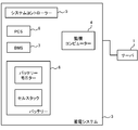
- Application example 1 In the functional block diagram of FIG. 5, the server 1 and the power storage system 3 are shown.
- the server 1 has the function of the determination device 10. That is, the server 1 determines whether or not maintenance of the power storage system is performed based on the time change of the state value indicating the state of the power storage system.
- the server 1 and the power storage system 3 are connected via a network such as the Internet, and exchange information with each other.
- the server 1 may be a cloud server.
- the power storage system 3 includes a monitoring computer 4, a system controller 5, a PCS (Power conditioning System) 6, a BMS (Battery Management System) 7, and a battery 8.
- PCS Power conditioning System
- BMS Battery Management System
- the system controller 5 controls the entire power storage system 3.
- the PCS 6 performs DC power / AC power conversion.
- the battery 8 stores electric power.
- the battery 8 includes, for example, a cell stack that stores energy, a battery monitor that monitors cell temperature, cell voltage, and the like.
- the BMS 7 controls the battery 8.
- the monitoring computer 4 acquires various measurement values from at least one of the system controller 5, the PCS 6, the BMS 7, and the battery 8. Then, the monitoring computer 4 transmits a part or all of the measurement values to the server 1 (determination device 10) as the state value described above.
- Application example 2 In the functional block diagram of FIG. 5, the server 1 and the power storage system 3 are shown.
- the monitoring computer 4 of the power storage system 3 has the function of the determination device 10. That is, the monitoring computer 4 of the power storage system 3 determines whether or not maintenance of the power storage system is performed based on the time change of the state value indicating the state of the power storage system.
- the server 1 and the power storage system 3 are connected via a network such as the Internet, and exchange information with each other.
- the server 1 may be a cloud server.
- the power storage system 3 includes a monitoring computer 4, a system controller 5, a PCS 6, a BMS 7, and a battery 8.
- the functions of the system controller 5, PCS 6, BMS 7, and battery 8 are the same as in Application Example 1.
- the monitoring computer 4 (determination device 10) acquires various measurement values from at least one of the system controller 5, the PCS 6, the BMS 7, and the battery 8. Then, the monitoring computer 4 processes some or all of the measured values as the above-described state values, and determines whether or not maintenance of the power storage system is performed, whether a timing condition is satisfied, and the like. The monitoring computer 4 transmits the determination result to the server 1. The server 1 stores the received determination result in association with each power storage system 3.
- FIG. 6 shows a functional block diagram of the third application example.
- Application Example 3 differs from Application Example 1 in that the monitoring computer 4 is provided outside the power storage system 3. Others are the same as Application Example 1.
- the server 1 has the function of the determination device 10. That is, the server 1 determines whether or not maintenance of the power storage system is performed based on the time change of the state value indicating the state of the power storage system.
- FIG. 6 shows a functional block diagram of application example 4.
- Application Example 4 differs from Application Example 2 in that the monitoring computer 4 is provided outside the power storage system 3. The rest is the same as Application Example 2.
- the monitoring computer 4 provided outside the power storage system 3 has the function of the determination device 10. That is, the monitoring computer 4 provided outside the power storage system 3 determines whether or not maintenance of the power storage system is performed based on the time change of the state value indicating the state of the power storage system.
- the determination device determines whether the maintenance is performed so as to satisfy a predetermined time condition. 5).
- the determination means includes Based on the state value, it is determined whether the power storage system is in a state requiring maintenance, A determination apparatus for determining whether the maintenance is performed within a predetermined period after determining that the state requires maintenance. 6).
- the determination unit is a determination device that determines that the maintenance is required when the state value exceeds or falls below a reference value. 7).
- a determination apparatus comprising: an output unit that requests execution of maintenance within the predetermined period when the determination unit determines that the power storage system is in a state requiring maintenance. 8).
- the determination device is configured to set the predetermined period shorter as the difference between the state value and the reference value is larger. 9. In the determination apparatus according to 7, The determination unit that requests execution of maintenance in the predetermined period, which is shorter as the difference between the state value and the reference value is larger. 10. In the determination device according to any one of 1 to 9, When the maintenance information is input, the acquisition unit acquires the state value of a period specified by the maintenance information, The determination device determines whether or not maintenance of the power storage system is performed based on a time change of the state value. 11. In the determination device according to any one of 1 to 10, The acquisition means acquires a state value at a predetermined time interval, The determination device determines whether the maintenance is being performed at the predetermined time interval.
- the acquisition means acquires a plurality of types of state values
- the determination unit is a determination device that identifies which maintenance is performed based on a trend change of the plurality of types of state values.
- the determination means includes, as the state value, a battery capacity, an insulation resistance, a temperature difference between the temperature of the power storage system and an outside air temperature, a change value of the battery capacity with respect to a temperature change, a battery SOC (state of charge): X Electric power per [%] (X is greater than 0 and less than 100), voltage range used for charge / discharge, and charge / discharge of the power storage system: Y [kW] (Y is greater than 0)
- a determination device using at least one of the temperature change rates per unit time of the power storage system.
Landscapes
- Physics & Mathematics (AREA)
- General Physics & Mathematics (AREA)
- Engineering & Computer Science (AREA)
- Manufacturing & Machinery (AREA)
- Chemical & Material Sciences (AREA)
- Chemical Kinetics & Catalysis (AREA)
- Electrochemistry (AREA)
- General Chemical & Material Sciences (AREA)
- Charge And Discharge Circuits For Batteries Or The Like (AREA)
- Tests Of Electric Status Of Batteries (AREA)
- Secondary Cells (AREA)
Abstract
La présente invention concerne un dispositif de détermination (10) comprenant : une unité d'acquisition (12) qui acquiert une valeur d'état indiquant l'état d'un système de stockage d'énergie ; et une unité de détermination (11) qui détermine si une maintenance a été effectuée ou non pour le système de stockage d'énergie, sur la base d'un changement temporel de la valeur d'état. Par exemple, lorsque le changement temporel de la valeur d'état est changé à partir de la tendance précédente, l'unité de détermination (11) détermine que la maintenance a été effectuée.
Priority Applications (3)
| Application Number | Priority Date | Filing Date | Title |
|---|---|---|---|
| EP17897078.6A EP3584873A4 (fr) | 2017-02-20 | 2017-10-19 | Dispositif de détermination, procédé de détermination, et programme |
| JP2018502434A JP6330983B1 (ja) | 2017-02-20 | 2017-10-19 | 判定装置、判定方法及びプログラム |
| US16/486,328 US20200233036A1 (en) | 2017-02-20 | 2017-10-19 | Determination apparatus, determination method, and non-transitory storage medium |
Applications Claiming Priority (2)
| Application Number | Priority Date | Filing Date | Title |
|---|---|---|---|
| JP2017029309 | 2017-02-20 | ||
| JP2017-029309 | 2017-02-20 |
Publications (1)
| Publication Number | Publication Date |
|---|---|
| WO2018150631A1 true WO2018150631A1 (fr) | 2018-08-23 |
Family
ID=63169228
Family Applications (1)
| Application Number | Title | Priority Date | Filing Date |
|---|---|---|---|
| PCT/JP2017/037821 WO2018150631A1 (fr) | 2017-02-20 | 2017-10-19 | Dispositif de détermination, procédé de détermination, et programme |
Country Status (4)
| Country | Link |
|---|---|
| US (1) | US20200233036A1 (fr) |
| EP (1) | EP3584873A4 (fr) |
| JP (1) | JP2018151391A (fr) |
| WO (1) | WO2018150631A1 (fr) |
Cited By (1)
| Publication number | Priority date | Publication date | Assignee | Title |
|---|---|---|---|---|
| WO2020137838A1 (fr) * | 2018-12-28 | 2020-07-02 | 株式会社Gsユアサ | Dispositif et procédé de traitement de données, et programme informatique |
Families Citing this family (2)
| Publication number | Priority date | Publication date | Assignee | Title |
|---|---|---|---|---|
| US20220005000A1 (en) * | 2018-11-20 | 2022-01-06 | Nec Corporation | Maintenance work instruction system, maintenance work instruction method, and program |
| DE102020112440A1 (de) | 2020-05-07 | 2021-11-11 | Audi Aktiengesellschaft | Verfahren zum Betreiben eines Steuergeräts für eine Energiespeichereinrichtung, Verfahren zum Betreiben einer Energiespeichereinrichtung sowie Steuergerät |
Citations (7)
| Publication number | Priority date | Publication date | Assignee | Title |
|---|---|---|---|---|
| JP2008232989A (ja) * | 2007-03-23 | 2008-10-02 | Matsushita Electric Ind Co Ltd | 蓄電装置 |
| JP2009187499A (ja) | 2008-02-08 | 2009-08-20 | Fujitsu Fsas Inc | 保守管理方法および保守管理システム |
| JP2015031674A (ja) * | 2013-08-07 | 2015-02-16 | 株式会社東芝 | 蓄電池状態監視装置及び蓄電池装置 |
| JP2015127676A (ja) | 2013-12-27 | 2015-07-09 | パナソニックIpマネジメント株式会社 | 蓄電池検査装置、蓄電池検査方法、蓄電池検査システム、及び、プログラム |
| JP2015227044A (ja) * | 2014-05-08 | 2015-12-17 | 株式会社リコー | 携帯型画像形成システム、画像形成装置、及び画像形成方法 |
| JP2016192759A (ja) | 2015-03-31 | 2016-11-10 | 京セラドキュメントソリューションズ株式会社 | 保守作業認証システム、画像形成装置及び保守作業管理装置 |
| JP2017029309A (ja) | 2015-07-30 | 2017-02-09 | 富士通株式会社 | 玩具 |
Family Cites Families (3)
| Publication number | Priority date | Publication date | Assignee | Title |
|---|---|---|---|---|
| US20130245973A1 (en) * | 2012-03-16 | 2013-09-19 | Smartmed Usa Inc. | Apparatus, computer program, method, and system for acquiring and analyzing battery metrics |
| JP5839093B2 (ja) * | 2013-09-04 | 2016-01-06 | トヨタ自動車株式会社 | 組電池管理システムおよび装置 |
| DE102013224509A1 (de) * | 2013-11-29 | 2015-06-03 | Robert Bosch Gmbh | Elektrische Energiespeichervorrichtung und Verfahren zum Betreiben einer elektrischen Energiespeichervorrichtung |
-
2017
- 2017-10-19 EP EP17897078.6A patent/EP3584873A4/fr not_active Withdrawn
- 2017-10-19 WO PCT/JP2017/037821 patent/WO2018150631A1/fr active Application Filing
- 2017-10-19 US US16/486,328 patent/US20200233036A1/en not_active Abandoned
-
2018
- 2018-04-25 JP JP2018084299A patent/JP2018151391A/ja active Pending
Patent Citations (7)
| Publication number | Priority date | Publication date | Assignee | Title |
|---|---|---|---|---|
| JP2008232989A (ja) * | 2007-03-23 | 2008-10-02 | Matsushita Electric Ind Co Ltd | 蓄電装置 |
| JP2009187499A (ja) | 2008-02-08 | 2009-08-20 | Fujitsu Fsas Inc | 保守管理方法および保守管理システム |
| JP2015031674A (ja) * | 2013-08-07 | 2015-02-16 | 株式会社東芝 | 蓄電池状態監視装置及び蓄電池装置 |
| JP2015127676A (ja) | 2013-12-27 | 2015-07-09 | パナソニックIpマネジメント株式会社 | 蓄電池検査装置、蓄電池検査方法、蓄電池検査システム、及び、プログラム |
| JP2015227044A (ja) * | 2014-05-08 | 2015-12-17 | 株式会社リコー | 携帯型画像形成システム、画像形成装置、及び画像形成方法 |
| JP2016192759A (ja) | 2015-03-31 | 2016-11-10 | 京セラドキュメントソリューションズ株式会社 | 保守作業認証システム、画像形成装置及び保守作業管理装置 |
| JP2017029309A (ja) | 2015-07-30 | 2017-02-09 | 富士通株式会社 | 玩具 |
Non-Patent Citations (1)
| Title |
|---|
| See also references of EP3584873A4 |
Cited By (4)
| Publication number | Priority date | Publication date | Assignee | Title |
|---|---|---|---|---|
| WO2020137838A1 (fr) * | 2018-12-28 | 2020-07-02 | 株式会社Gsユアサ | Dispositif et procédé de traitement de données, et programme informatique |
| JP2020107577A (ja) * | 2018-12-28 | 2020-07-09 | 株式会社Gsユアサ | データ処理装置、データ処理方法、及びコンピュータプログラム |
| JP7310137B2 (ja) | 2018-12-28 | 2023-07-19 | 株式会社Gsユアサ | データ処理装置、データ処理方法、及びコンピュータプログラム |
| US12013439B2 (en) | 2018-12-28 | 2024-06-18 | Gs Yuasa International Ltd. | Data processor, data processing method, and computer program |
Also Published As
| Publication number | Publication date |
|---|---|
| JP2018151391A (ja) | 2018-09-27 |
| EP3584873A1 (fr) | 2019-12-25 |
| US20200233036A1 (en) | 2020-07-23 |
| EP3584873A4 (fr) | 2020-01-15 |
Similar Documents
| Publication | Publication Date | Title |
|---|---|---|
| JP5842182B2 (ja) | 蓄電池移転支援装置および蓄電池移転支援方法 | |
| US9772666B1 (en) | Multi-level battery management | |
| WO2018150631A1 (fr) | Dispositif de détermination, procédé de détermination, et programme | |
| US7349828B1 (en) | Estimating an electronic device condition | |
| JP6872058B2 (ja) | 監視システム、サーバ、端末装置、監視方法、及び、記憶媒体 | |
| CN105872061B (zh) | 一种服务器集群管理方法、装置及系统 | |
| WO2018154845A1 (fr) | Dispositif de gestion, procédé de gestion et programme | |
| CN106063068B (zh) | 设备控制装置以及需求响应方法 | |
| JPWO2019176063A1 (ja) | 異常検知装置、異常検知方法およびプログラム | |
| JPWO2018105154A1 (ja) | 電力管理装置、電力管理システム、電力管理方法、及び、プログラム | |
| JP6330983B1 (ja) | 判定装置、判定方法及びプログラム | |
| US20190341783A1 (en) | Determination apparatus, surveillance apparatus, energy storage system, surveillance system, determination method, surveillance method, operation method of energy storage system, and non-transitory storage medium | |
| CN106291174A (zh) | 一种寿命获得方法、装置、电子设备及服务器 | |
| CN116485078B (zh) | 一种多类型能源能效管理方法、装置、电子设备及介质 | |
| JP2013175120A (ja) | 電力使用状況取得システム | |
| US11733304B2 (en) | Determination apparatus | |
| JP6773889B2 (ja) | 蓄電池の劣化予測装置、蓄電池システム、方法及びプログラム | |
| WO2018168053A1 (fr) | Dispositif de gestion d'énergie, procédé de gestion d'énergie et programme | |
| JP6856063B2 (ja) | 端末装置、制御装置、サーバ、評価方法及びプログラム | |
| US10671051B2 (en) | Thermal event detection in electrical systems | |
| JP6835063B2 (ja) | 端末装置、制御装置、サーバ、評価方法及びプログラム | |
| US20240273647A1 (en) | Information processing apparatus, information processing method, and recording medium | |
| US20240088688A1 (en) | Storage battery management device, storage battery management method, and recording medium | |
| JP2022020475A (ja) | 更新管理装置、配信方法およびプログラム | |
| CN118346640A (zh) | 一种积灰检测方法、装置、分布式储能系统和存储介质 |
Legal Events
| Date | Code | Title | Description |
|---|---|---|---|
| ENP | Entry into the national phase |
Ref document number: 2018502434 Country of ref document: JP Kind code of ref document: A |
|
| 121 | Ep: the epo has been informed by wipo that ep was designated in this application |
Ref document number: 17897078 Country of ref document: EP Kind code of ref document: A1 |
|
| NENP | Non-entry into the national phase |
Ref country code: DE |
|
| WWE | Wipo information: entry into national phase |
Ref document number: 2017897078 Country of ref document: EP |