WO2018147365A1 - 熱交換ユニット及びヒートポンプユニット - Google Patents
熱交換ユニット及びヒートポンプユニット Download PDFInfo
- Publication number
- WO2018147365A1 WO2018147365A1 PCT/JP2018/004382 JP2018004382W WO2018147365A1 WO 2018147365 A1 WO2018147365 A1 WO 2018147365A1 JP 2018004382 W JP2018004382 W JP 2018004382W WO 2018147365 A1 WO2018147365 A1 WO 2018147365A1
- Authority
- WO
- WIPO (PCT)
- Prior art keywords
- panel
- heat exchanger
- heat
- drain
- pair
- Prior art date
- Legal status (The legal status is an assumption and is not a legal conclusion. Google has not performed a legal analysis and makes no representation as to the accuracy of the status listed.)
- Ceased
Links
Images

Classifications
-
- F—MECHANICAL ENGINEERING; LIGHTING; HEATING; WEAPONS; BLASTING
- F25—REFRIGERATION OR COOLING; COMBINED HEATING AND REFRIGERATION SYSTEMS; HEAT PUMP SYSTEMS; MANUFACTURE OR STORAGE OF ICE; LIQUEFACTION SOLIDIFICATION OF GASES
- F25B—REFRIGERATION MACHINES, PLANTS OR SYSTEMS; COMBINED HEATING AND REFRIGERATION SYSTEMS; HEAT PUMP SYSTEMS
- F25B30/00—Heat pumps
- F25B30/02—Heat pumps of the compression type
-
- F—MECHANICAL ENGINEERING; LIGHTING; HEATING; WEAPONS; BLASTING
- F24—HEATING; RANGES; VENTILATING
- F24F—AIR-CONDITIONING; AIR-HUMIDIFICATION; VENTILATION; USE OF AIR CURRENTS FOR SCREENING
- F24F1/00—Room units for air-conditioning, e.g. separate or self-contained units or units receiving primary air from a central station
- F24F1/06—Separate outdoor units, e.g. outdoor unit to be linked to a separate room comprising a compressor and a heat exchanger
- F24F1/14—Heat exchangers specially adapted for separate outdoor units
- F24F1/16—Arrangement or mounting thereof
-
- F—MECHANICAL ENGINEERING; LIGHTING; HEATING; WEAPONS; BLASTING
- F24—HEATING; RANGES; VENTILATING
- F24F—AIR-CONDITIONING; AIR-HUMIDIFICATION; VENTILATION; USE OF AIR CURRENTS FOR SCREENING
- F24F1/00—Room units for air-conditioning, e.g. separate or self-contained units or units receiving primary air from a central station
- F24F1/06—Separate outdoor units, e.g. outdoor unit to be linked to a separate room comprising a compressor and a heat exchanger
- F24F1/36—Drip trays for outdoor units
-
- F—MECHANICAL ENGINEERING; LIGHTING; HEATING; WEAPONS; BLASTING
- F24—HEATING; RANGES; VENTILATING
- F24F—AIR-CONDITIONING; AIR-HUMIDIFICATION; VENTILATION; USE OF AIR CURRENTS FOR SCREENING
- F24F13/00—Details common to, or for air-conditioning, air-humidification, ventilation or use of air currents for screening
- F24F13/22—Means for preventing condensation or evacuating condensate
-
- F—MECHANICAL ENGINEERING; LIGHTING; HEATING; WEAPONS; BLASTING
- F24—HEATING; RANGES; VENTILATING
- F24F—AIR-CONDITIONING; AIR-HUMIDIFICATION; VENTILATION; USE OF AIR CURRENTS FOR SCREENING
- F24F13/00—Details common to, or for air-conditioning, air-humidification, ventilation or use of air currents for screening
- F24F13/30—Arrangement or mounting of heat-exchangers
-
- F—MECHANICAL ENGINEERING; LIGHTING; HEATING; WEAPONS; BLASTING
- F25—REFRIGERATION OR COOLING; COMBINED HEATING AND REFRIGERATION SYSTEMS; HEAT PUMP SYSTEMS; MANUFACTURE OR STORAGE OF ICE; LIQUEFACTION SOLIDIFICATION OF GASES
- F25B—REFRIGERATION MACHINES, PLANTS OR SYSTEMS; COMBINED HEATING AND REFRIGERATION SYSTEMS; HEAT PUMP SYSTEMS
- F25B39/00—Evaporators; Condensers
-
- F—MECHANICAL ENGINEERING; LIGHTING; HEATING; WEAPONS; BLASTING
- F25—REFRIGERATION OR COOLING; COMBINED HEATING AND REFRIGERATION SYSTEMS; HEAT PUMP SYSTEMS; MANUFACTURE OR STORAGE OF ICE; LIQUEFACTION SOLIDIFICATION OF GASES
- F25B—REFRIGERATION MACHINES, PLANTS OR SYSTEMS; COMBINED HEATING AND REFRIGERATION SYSTEMS; HEAT PUMP SYSTEMS
- F25B41/00—Fluid-circulation arrangements
Definitions
- This disclosure relates to a heat exchange unit and a heat pump unit.
- hot water at 90 ° C. or higher can be supplied by using CO 2 as a refrigerant in a hot water supply unit including equipment constituting a heat pump cycle and making CO 2 in a supercritical state on the outlet side of the compressor.
- a hot water supply unit an air heat exchanger is used as an evaporator that evaporates a refrigerant such as CO 2 using air as a heat source.
- a pair of air heat exchangers provided along the vertical direction are arranged to face each other, and a fan that allows air to pass through the pair of air heat exchangers is located above the pair of air heat exchangers.
- An arranged heat exchange unit is disclosed.
- Patent Document 1 In a heat exchange unit in which a pair of air heat exchangers provided in the vertical direction as in the heat exchange unit described in Patent Document 1 described above are arranged to face each other, generally, a pair of air heat exchangers An opening for air circulation is provided above the region sandwiched between the two, and a drain pan for receiving drain condensed by the air heat exchanger is provided below the region.
- a pair of air heat exchangers An opening for air circulation is provided above the region sandwiched between the two, and a drain pan for receiving drain condensed by the air heat exchanger is provided below the region.
- Patent Document 1 described above does not disclose any configuration for preventing the drainage port from being clogged with foreign matter.
- At least one embodiment aims at providing the heat exchange unit and heat pump unit which can prevent clogging of the drain outlet of a drain pan by a foreign material in view of the above-mentioned subject.
- the heat exchange unit is: A panel heat exchanger provided along the vertical direction; A drain pan provided below the panel heat exchanger and having a drain port; A clogging preventing member that is disposed in the drain port and prevents foreign matter other than the drain generated in the panel heat exchanger from entering the drain port; Is provided.
- the clogging preventing member that prevents foreign matter other than the drain generated in the panel heat exchanger from entering the drain port is disposed at the drain port. It does not invade and can prevent clogging of the drain port with foreign matter.
- the clogging prevention member is A mesh-like base through which the drain can pass; A plurality of needles provided on the base and projecting upward from the base; Have According to the configuration of (2) above, the entry of foreign matter from above can be prevented at the upper end of the needle without hindering the flow of drain, so the effect of preventing clogging of the drain port is high.
- the plurality of needles are provided at the base, the plurality of needles are integrated, and the clogging prevention member can be easily installed.
- the plurality of needles are spaced apart from each other and have the same height. According to the configuration of (3) above, the plurality of needles are spaced apart from each other and have the same height, so that the entry of foreign matter from above is effectively prevented at the upper end of the needle. it can.
- the base portion of the clogging prevention member has a flat bottom surface, and the plurality of needles are orthogonal to the bottom surface. It is provided along.
- the base has a flat bottom surface, and the plurality of needles are provided along the direction orthogonal to the bottom surface. Can be effectively blocked.
- the base has a flat bottom surface, the arranged clogging preventing member is less likely to fall and is stable.
- the plurality of needles are provided on the base portion having a flat bottom surface, the clogging prevention member can be easily installed.
- a heat exchange medium flow path is formed inside the panel heat exchanger, and air is the panel heat. It is configured to pass through the front and back surfaces of the exchanger.
- the heat exchange unit having the above configuration foreign matter does not enter the drain port, and the drain port can be prevented from being clogged with foreign matter.
- the heat exchange medium flow path is formed inside the panel heat exchanger and the air can pass through the front and back surfaces of the panel heat exchanger, the generated drain can be reliably discharged to the drain pan. .
- the drain pan has a groove extending along the longitudinal direction of the panel heat exchanger,
- the clogging preventing member extends along the longitudinal direction in the groove. According to the configuration of (6) above, since the groove extends along the longitudinal direction of the panel heat exchanger, the drain generated in the panel heat exchanger can be collected effectively. Moreover, since the clogging preventing member extends along the longitudinal direction in the groove, the foreign matter flowing in the groove together with the drain can be effectively prevented by the clogging preventing member in the groove.
- the panel heat exchanger in the configuration of the above (6), includes a pair of the panel heat exchangers arranged so that the interval is narrowed from the upper side to the lower side.
- the groove extends along the longitudinal direction of the pair of panel heat exchangers in a region between the pair of panel heat exchangers.
- the panel-like heat exchanger includes a pair of the panel-like heat exchangers arranged so that the interval is narrowed from the upper side to the lower side,
- the drain pan is disposed in a lower portion of the pair of panel heat exchangers and a region between the pair of panel heat exchangers.
- the heat pump unit is: A box-shaped casing; A heat exchanging unit provided in an upper region in the box-shaped casing, and having the structure according to any one of the above (1) to (8); A heat pump cycle constituent device provided in a lower region in the box-shaped casing, in which the panel heat exchanger is incorporated as an evaporator; Is provided.
- the clogging preventing member that prevents foreign matter other than the drain generated in the panel heat exchanger from entering the drain port is disposed in the drain port, the foreign matter is placed in the drain port. It does not invade and can prevent clogging of the drain port with foreign matter.
- the clogging of the drain port due to foreign matter can be prevented.
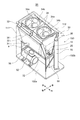
- FIG. It is a perspective view of the appearance of a heat pump unit concerning one embodiment, (a) is a perspective view which looked at a heat pump unit concerning one embodiment from the front, and (b) is a heat pump unit concerning one embodiment from back.
- FIG. It is a perspective view which shows typically the internal structure of the heat pump unit which concerns on one Embodiment. It is a figure showing the whole heat pump unit composition concerning one embodiment.
- an expression indicating that things such as “identical”, “equal”, and “homogeneous” are in an equal state not only represents an exactly equal state, but also has a tolerance or a difference that can provide the same function. It also represents the existing state.
- expressions representing shapes such as quadrangular shapes and cylindrical shapes represent not only geometrically strict shapes such as quadrangular shapes and cylindrical shapes, but also irregularities and chamfers as long as the same effects can be obtained. A shape including a part or the like is also expressed.
- the expressions “comprising”, “comprising”, “comprising”, “including”, or “having” one constituent element are not exclusive expressions for excluding the existence of other constituent elements.
- FIG. 1 is a perspective view of an appearance of a heat pump unit according to an embodiment
- FIG. 1A is a perspective view of the heat pump unit according to the embodiment as viewed from the front
- FIG. It is the perspective view which looked at the heat pump unit which concerns on a form from back
- FIG. 2 is a perspective view schematically showing the internal structure of the heat pump unit according to the embodiment.
- the front-rear direction and the left-right direction of the heat pump unit are defined as shown in each drawing.
- the vertical direction of the heat pump unit is the same as the vertical direction on the paper surface of each drawing.
- the front surface of the heat pump unit is also referred to as a front surface
- the rear surface is also referred to as a back surface.
- a heat pump unit 50 includes a box-shaped casing 100 having a substantially rectangular parallelepiped shape as shown in FIG. 1 and a heat pump cycle component device 52 arranged inside the box-shaped casing 100 as shown in FIG. Prepare.
- the box-shaped casing 100 is provided on an upper portion of a substantially rectangular base plate 51. That is, four support columns 101 are erected at the four corners of the base plate 51.
- An air outlet 112 described later is provided on the upper surface of the box-shaped casing 100, and the periphery of the air outlet 112 is covered with the top plate 102.
- the box-shaped casing 100 has four side surfaces, that is, a front surface (front surface) 100a, a rear surface (back surface) 100b, a right side surface 100c, and a left side surface 100d.
- An air intake port 111 which will be described later, is formed on the front surface 100a and the back surface 100b.
- the front surface 100a, the back surface 100b, the right side surface 100c, and the left side surface 100d are covered with a panel plate except for the air intake port 111.
- a panel plate covering the lower area of the back surface 100b is referred to as a back lower panel plate 103.
- the lower back panel plate 103 is attached so that it can be easily attached and detached for maintenance of the drain pan 10 described later.
- An opening 104 is provided in the panel plate covering the area on the right side of the front surface 100a.
- the opening 104 is an opening for operating a touch panel type operation panel (not shown) for operating the heat pump unit 50.
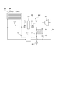
- FIG. 3 is a diagram illustrating an overall configuration of the heat pump unit 50 according to an embodiment.
- the heat pump cycle component device 52 includes a compressor 56, a gas cooler 58, an internal heat exchanger 64, and a panel heat exchanger 36.
- the refrigerant (for example, CO 2 ) compressed by the compressor 56 is supplied to the gas cooler 58 via the refrigerant circulation path 54 and is cooled by the cooling water flowing through the cooling water path 60 by the gas cooler 58.
- the cooling water channel 60 is provided with a pump 62 that sends the cooling water to the gas cooler 58.
- the refrigerant cooled by the gas cooler 58 is cooled by exchanging heat with the refrigerant sent from the panel heat exchanger 36 by the internal heat exchanger 64 and then depressurized via the expansion valve 66. Thereafter, the refrigerant is heated by the panel heat.
- the exchanger 36 vaporizes air as a heat source. That is, the panel-shaped heat exchanger 36 has a heat exchange medium flow path, that is, a refrigerant flow path formed therein, and is configured to allow air to pass through the front and back surfaces of the panel-shaped heat exchanger 36. It is incorporated in the heat pump cycle component device 52.
- the vaporized refrigerant is heated by exchanging heat with the refrigerant sent from the gas cooler 58 by the internal heat exchanger 64 and then sent again to the compressor 56 to be compressed.
- a bypass path 68 that branches from the refrigerant circulation path 54 on the downstream side of the gas cooler 58 and is connected to the refrigerant circulation path 54 on the downstream side of the expansion valve 66 is connected to the refrigerant circulation path 54.
- a refrigerant tank 70 is provided in the bypass path 68, and electromagnetic valves 72 and 74 are provided on the upstream side and the downstream side of the refrigerant tank 70.
- a part of the refrigerant in the refrigerant circulation path 54 is stored in the refrigerant tank 70, or the refrigerant stored in the refrigerant tank 70 is returned to the refrigerant circulation path 54, whereby the amount of refrigerant flowing through the refrigerant circulation path 54 can be adjusted.
- the hot water heated by the gas cooler 58 can be supplied to a customer as a heat source.
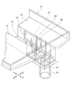
- a pair of panel heat exchangers 36 provided along the vertical direction inside the box-shaped casing 100 are arranged facing each other.
- a fan 34 that allows air to pass through the pair of panel heat exchangers 36 is disposed above the pair of panel heat exchangers 36.
- the pair of panel heat exchangers 36 provided along the vertical direction is supported from below by the heat exchanger frame 31 installed on the base plate 51.
- a fan base 32 for attaching the fan 34 is attached to the upper ends of the pair of panel heat exchangers 36, and the fan 34 is attached to the fan base 32.
- the fan 34 is provided with a propeller-type blade 34a, and air is blown through the opening 34b of the casing.
- a heat pump cycle component device 52 such as a compressor 56 and a gas cooler 58 is provided in a lower region inside the box-shaped casing 100.
- the compressor 56, the gas cooler 58, the refrigerant tank 70, and the like are fixed on the base plate 51.
- an air intake port 111 is formed in the upper region of the front surface 100 a and the back surface 100 b of the box-shaped casing 100.
- the pair of panel-like heat exchangers 36 are provided so as to face the two air intake ports 111, and are arranged in a V shape so that the distance between the pair of panel-like heat exchangers 36 decreases toward the bottom.
- Each of the pair of panel heat exchangers 36 is disposed such that the longitudinal direction thereof is along the left-right direction of the heat pump unit 50.
- an air flow a (see FIG. 2) that flows from the air intake ports 111 on the front surface 100a and the back surface 100b, passes through the pair of panel heat exchangers 36, and reaches the air outlet 112 is formed.
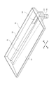
- FIG. 4 is a perspective view showing the appearance of the drain pan 10.
- the drain pan 10 is a dish-shaped member for collecting drain that is generated when moisture in the air is condensed in the pair of panel heat exchangers 36.
- the drain pan 10 has a front bottom plate 11, a rear bottom plate 12, and a groove 13 extending between the front and rear bottom plates 11, 12 in the left-right direction, that is, in the longitudinal direction of the panel heat exchanger 36.
- the bottom plates 11 and 12 have a slope that descends toward the groove 13.
- the bottom surface of the groove 13 has a downward slope that is downwardly inclined, and a drain port 14 for draining is provided near the right end of the bottom surface.
- a short pipe 15 extending downward is connected to the drain port 14, and one end of a hose (not shown) is connected to the lower end of the short pipe 15. The other end of the hose (not shown) is connected to a drain discharge nozzle provided on the back surface 100b.
- the drain pan 10 is provided with a maintenance inspection port 16 in the vicinity of the drain port 14.
- the inspection port 16 is opened, for example, on the side surface on the back side of the groove 13 and is covered with a cover (not shown) that can be attached and detached so that the drain does not leak.
- the drain generated in the pair of panel heat exchangers 36 is collected in the drain pan 10.
- the heat pump unit 50 is sandwiched between the inside of the box-shaped casing 100, that is, the pair of panel heat exchangers 36, through the air outlet 112 and the opening 34b of the casing of the fan 34.
- Rainwater enters the area.
- This invading rainwater is also collected in the drain pan 10. That is, the drain generated in the pair of panel heat exchangers 36 and the rainwater entering the heat pump unit 50 flow down to the bottom plates 11 and 12 of the drain pan 10 and flow into the grooves 13.
- Drain and rainwater flowing into the groove 13 flows in the groove 13 toward the drain port 14 on the right end side of the groove 13, and drains from the back surface 100 b through the short tube 15 and a hose (not shown). Is discharged from the heat nozzle to the outside of the heat pump unit 50.
- the air outlet 112 and the opening 34b of the casing of the fan 34 are provided above the region sandwiched between the pair of panel heat exchangers 36.
- foreign matter hereinafter simply referred to as foreign matter
- the heat pump unit 50 is set outdoors, there is a high risk that foreign matter will enter the box-shaped casing 100 through the air outlet 112 and the opening 34b.
- Examples of the foreign matter that enters the inside of the box-shaped casing 100 include tree leaves.
- the foreign matter that has entered the inside of the box-shaped casing 100 falls directly on the drain port 14 or reaches the drain port 14 by flowing down the bottom plates 11 and 12 and the groove 13 together with the drain.
- the foreign matter that has reached the drain port 14 may cover the drain port 14 or may flow into the short pipe 15 or a hose (not shown) and become clogged inside, thereby hindering drainage.
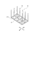
- FIG. 5 is a perspective view showing a leaf fence 20 according to an embodiment installed in the drain pan 10 and the drain port 14, and FIG. 6 is a perspective view of the leaf fence 20 according to the embodiment.
- the heat exchange unit 30 of one embodiment includes a panel heat exchanger 36 provided along the vertical direction, a drain pan 10 provided below the panel heat exchanger 36 and having a drain port 14, and a drain.
- a leaf fence 20 that is a clogging prevention member that is disposed at the opening 14 and prevents foreign matter other than the drain generated by the panel heat exchanger 36 from entering the drain opening 14 is provided.
- the heat exchange unit 30 of one embodiment is provided in the upper region in the box-shaped casing 100. In the heat exchange unit 30 of one embodiment, since the leaf fence 20 that prevents foreign matter other than the drain generated in the panel heat exchanger 36 from entering the drain port 14 is disposed at the drain port 14, Does not enter the drain port 14 and can prevent the drain port 14 from being clogged with foreign matter.
- the leaf fence 20 of one Embodiment includes a mesh-like base portion 21 through which drain can pass and a plurality of needles 22 provided on the base portion 21 and projecting upward from the base portion 21.
- the base 21 has a flat bottom surface 21a, and the plurality of needles 22 are provided along a direction orthogonal to the bottom surface 21a.
- the plurality of needles 22 are spaced apart from each other and have the same height.
- the leaf fence 20 of one embodiment is placed on the bottom surface of the groove 13 and covers the drain port 14.
- the dimension in the front-rear direction is substantially equal to the width of the groove 13, that is, the dimension in the front-rear direction of the groove 13.
- the dimension of the left-right direction of the leaf fence 20 of one embodiment is the state in which the right end of the leaf fence 20 is in contact with the right side (downstream side) side wall of the groove 13 and the left end of the leaf fence 20 is a drain port. 14 is set to be located on the left side of the left end. Thereby, even if the leaf fence 20 moves to the downstream side of the groove 13 due to the flow of the drain, the base 21 reliably covers the drain port 14, so that foreign matter can be prevented from entering the drain port 14.
- the horizontal dimension of the leaf fence 20, that is, the dimension along the longitudinal direction of the groove 13 should be set in consideration of the position of the center of gravity of the fence fence 20 so as not to fall in the horizontal direction in the groove 13. Is desirable.
- foreign matter from above is blocked by the upper ends of the plurality of needles 22, and foreign matter flowing through the groove 13 together with drains is lined up in the front-rear direction on the left side, that is, upstream of the groove 13. Blocked by the side surfaces of the plurality of needles 22.
- foreign matter that has fallen without being blocked by the upper end of the needle 22 is blocked by the mesh-shaped base 21.
- the foreign matter that has passed between the needles 22 arranged on the upstream side of the groove 13 is the side surface of the needle 22 on the downstream side of the needles 22 or the mesh-like base 21. Is blocked.
- the needle 22 and the needle 22 are separated from each other, and the base 21 is also mesh-shaped, so that the drain flows to the drain port 14 without being inhibited by the leaf fence 20.
- foreign substances accumulated on the top and side surfaces of the leaf fence 20 can be removed as follows. First, the lower back panel 103 of the heat pump unit 50 shown in FIG. Accordingly, the inspection port 16 provided on the back side of the groove 13 of the drain pan 10 can be accessed from the back surface 100 b of the heat pump unit 50. Next, the inspection port 16 can be opened by removing a lid (not shown) that covers the inspection port 16, and the accumulated foreign matter can be removed or the leaf fence 20 can be removed.
- a commercially available member for avoiding pigeons may be used as the leaf fence 20. Thereby, the leaf fence 20 can be obtained at low cost.
- the leaf fence 20 includes a mesh-like base portion 21 through which drain can pass and a plurality of needles 22 provided on the base portion 21 and projecting upward from the base portion 21.
- the plurality of needles 22 are spaced apart from each other and have an equivalent height. Thereby, the entry of foreign matter from above can be effectively prevented at the upper end of the needle 22.
- base 21 of leaf fence 20 has flat bottom 21a, and a plurality of needles 22 are provided along the direction orthogonal to bottom 21a. Thereby, the entry of foreign matter from above can be effectively prevented at the upper end of the needle 22. Moreover, since the base part 21 has the flat bottom face 21a, the arranged leaf fence 20 becomes difficult to fall down and is stabilized. Moreover, since the several needle
- a refrigerant flow path is formed inside the panel heat exchanger 36, and air can pass through the front and back surfaces of the panel heat exchanger 36.
- a foreign material does not penetrate
- the refrigerant flow path is formed inside the panel heat exchanger 36 and the air can pass through the front and back surfaces of the panel heat exchanger. Therefore, the generated drain is transferred to the drain pan 10. Can be discharged reliably.
- the drain pan 10 has the groove 13 that extends along the longitudinal direction of the panel heat exchanger 36.
- the leaf fence 20 extends along the longitudinal direction of the panel heat exchanger 36 in the groove 13. Since the groove 13 extends along the longitudinal direction of the panel heat exchanger 36, the drain generated by the panel heat exchanger 36 can be collected effectively. Moreover, since the leaf fence 20 extends along the longitudinal direction of the panel heat exchanger 36 in the groove 13, the foreign material flowing in the groove 13 together with the drain is caused by the leaf fence 20 in the groove 13. Can be effectively blocked.
- the panel-shaped heat exchanger 36 includes a pair of panel-shaped heat exchangers 36 that are arranged so that the distance between the panel-shaped heat exchanger 36 decreases from the top to the bottom.
- the drain pan 10 is disposed in a region between the lower part of the pair of panel heat exchangers 36 and the pair of panel heat exchangers 36.
- drain pan 10 is arrange
- the groove 13 extends in the region between the pair of panel heat exchangers 36 along the longitudinal direction of the pair of panel heat exchangers 36.
- a heat pump unit 50 is provided in a box-shaped casing 100, the above-described heat exchange unit 30 provided in an upper region in the box-shaped casing 100, and a lower region in the box-shaped casing 100.
- the heat exchanger 36 includes a heat pump cycle component 52 in which the heat exchanger 36 is incorporated as an evaporator.
- the leaf fence 20 that prevents foreign matter other than the drain generated by the panel heat exchanger 36 from entering the drain port 14 is disposed at the drain port 14, Does not enter the drain port 14 and can prevent the drain port 14 from being clogged with foreign matter. Moreover, since the leaf fence 20 prevents foreign matter from entering the drain port 14, foreign matter can be prevented from flowing into the short pipe 15 or a hose (not shown) and being clogged inside. Thereby, it is possible to prevent the discharge of the drain due to the foreign matter, and to reduce the maintenance frequency such as removing the foreign matter, thereby reducing the maintenance cost.
- the leaf fence 20 has a plurality of needles 22 as shown in FIG.
- the upper end of the needle 22 may not be sharp.
- the leaf fence 20 may have a plurality of rod-shaped parts whose top ends are not sharp instead of the needles 22 whose top ends are sharp.
- the leaf fence 20 has a plurality of needles 22 arranged in a straight line along the front-rear direction and the left-right direction.
- the plurality of needles 22 are not necessarily arranged in a straight line along the front-rear direction and the left-right direction, and the plurality of needles 22 are arranged so that the upper ends of the needles 22 are appropriately separated from each other in the front-rear direction and the left-right direction. Needles 22 need only be arranged, and the intervals are not necessarily equal.
- the heights of the upper ends of the plurality of needles 22 are substantially equal, but the heights of the upper ends of the plurality of needles 22 may be different from each other.
- the needle 22 is disposed at the intersection of the portion extending in the front-rear direction and the portion extending in the left-right direction in the base portion 21.
- the needle 22 may be disposed at a portion other than the intersecting portion in the base portion 21.
- the leaf fence 20 has a mesh-like base portion 21 and a plurality of needles 22 protruding upward from the base portion 21.
- the upper surface of the leaf fence 20, that is, the upper ends of the plurality of needles 22 may be connected to the upper ends of the adjacent needles 22 to form the same shape as the mesh-shaped base 21.
- a rectangular parallelepiped formed so that at least the top surface, the bottom surface, and the left side (upstream side) side surface are formed in a mesh shape so as not to disturb the flow of the drain.
- a member having a shape may be used as a clogging prevention member.
- the base 21 of the leaf fence 20 has a flat bottom surface 21a, and the plurality of needles 22 are provided along a direction orthogonal to the bottom surface 21a.
- the bottom surface 21a may have a step, or the bottom surface 21a may be curved.
- the needle 22 does not necessarily have to be provided along the direction orthogonal to the bottom surface 21a.
- the needle 22 may extend obliquely upward or may have a curved portion. Good.
- the drain pan 10 has the groove 13 extending along the longitudinal direction of the panel heat exchanger 36.
- the groove 13 may extend along a direction different from the longitudinal direction of the panel heat exchanger 36.
- the leaf fence 20 extended along the longitudinal direction of the panel-shaped heat exchanger 36 in the groove
- the pair of panel heat exchangers 36 are arranged in a V shape so that the distance between the pair of panel heat exchangers 36 decreases toward the bottom.
- the pair of panel-like heat exchangers 36 may be arranged, for example, so that the distance between the pair of panel-like heat exchangers 36 is equal between the upper side and the lower side. It may be arranged in a letter shape.
- the heat pump unit 50 including the devices that configure the heat pump cycle has been described.
- the above-described content of the heat pump unit 50 can be applied to a refrigeration unit including the devices that configure the refrigeration cycle.
Landscapes
- Engineering & Computer Science (AREA)
- Mechanical Engineering (AREA)
- General Engineering & Computer Science (AREA)
- Physics & Mathematics (AREA)
- Thermal Sciences (AREA)
- Chemical & Material Sciences (AREA)
- Combustion & Propulsion (AREA)
- Devices For Blowing Cold Air, Devices For Blowing Warm Air, And Means For Preventing Water Condensation In Air Conditioning Units (AREA)
- Other Air-Conditioning Systems (AREA)
- Air-Conditioning Room Units, And Self-Contained Units In General (AREA)
- Heat-Pump Type And Storage Water Heaters (AREA)
Applications Claiming Priority (2)
| Application Number | Priority Date | Filing Date | Title |
|---|---|---|---|
| JP2017023348A JP6826454B2 (ja) | 2017-02-10 | 2017-02-10 | 熱交換ユニット及びヒートポンプユニット |
| JP2017-023348 | 2017-02-10 |
Publications (1)
| Publication Number | Publication Date |
|---|---|
| WO2018147365A1 true WO2018147365A1 (ja) | 2018-08-16 |
Family
ID=63108330
Family Applications (1)
| Application Number | Title | Priority Date | Filing Date |
|---|---|---|---|
| PCT/JP2018/004382 Ceased WO2018147365A1 (ja) | 2017-02-10 | 2018-02-08 | 熱交換ユニット及びヒートポンプユニット |
Country Status (3)
| Country | Link |
|---|---|
| JP (1) | JP6826454B2 (enExample) |
| CN (2) | CN208312764U (enExample) |
| WO (1) | WO2018147365A1 (enExample) |
Cited By (1)
| Publication number | Priority date | Publication date | Assignee | Title |
|---|---|---|---|---|
| CN109442721A (zh) * | 2018-11-16 | 2019-03-08 | 无锡同方人工环境有限公司 | 一种风冷模块机组外框 |
Families Citing this family (2)
| Publication number | Priority date | Publication date | Assignee | Title |
|---|---|---|---|---|
| JP6826454B2 (ja) * | 2017-02-10 | 2021-02-03 | 株式会社前川製作所 | 熱交換ユニット及びヒートポンプユニット |
| JPWO2023209767A1 (enExample) * | 2022-04-25 | 2023-11-02 |
Citations (6)
| Publication number | Priority date | Publication date | Assignee | Title |
|---|---|---|---|---|
| JPS51131845U (enExample) * | 1975-04-16 | 1976-10-23 | ||
| JPS5257876U (enExample) * | 1975-10-21 | 1977-04-26 | ||
| JPS53155146U (enExample) * | 1977-05-13 | 1978-12-06 | ||
| JPS62213621A (ja) * | 1986-03-12 | 1987-09-19 | Toshiba Corp | 空気調和機 |
| JPS62173619U (enExample) * | 1986-04-25 | 1987-11-04 | ||
| JP2007163017A (ja) * | 2005-12-13 | 2007-06-28 | Toyo Kiyaria Kogyo Kk | 熱交換ユニット |
Family Cites Families (3)
| Publication number | Priority date | Publication date | Assignee | Title |
|---|---|---|---|---|
| JPS5546901Y2 (enExample) * | 1976-05-07 | 1980-11-04 | ||
| JPS5678917U (enExample) * | 1979-11-22 | 1981-06-26 | ||
| JP6826454B2 (ja) * | 2017-02-10 | 2021-02-03 | 株式会社前川製作所 | 熱交換ユニット及びヒートポンプユニット |
-
2017
- 2017-02-10 JP JP2017023348A patent/JP6826454B2/ja active Active
-
2018
- 2018-02-08 WO PCT/JP2018/004382 patent/WO2018147365A1/ja not_active Ceased
- 2018-02-08 CN CN201820222301.2U patent/CN208312764U/zh not_active Withdrawn - After Issue
- 2018-02-08 CN CN201810127351.7A patent/CN108413650B/zh active Active
Patent Citations (6)
| Publication number | Priority date | Publication date | Assignee | Title |
|---|---|---|---|---|
| JPS51131845U (enExample) * | 1975-04-16 | 1976-10-23 | ||
| JPS5257876U (enExample) * | 1975-10-21 | 1977-04-26 | ||
| JPS53155146U (enExample) * | 1977-05-13 | 1978-12-06 | ||
| JPS62213621A (ja) * | 1986-03-12 | 1987-09-19 | Toshiba Corp | 空気調和機 |
| JPS62173619U (enExample) * | 1986-04-25 | 1987-11-04 | ||
| JP2007163017A (ja) * | 2005-12-13 | 2007-06-28 | Toyo Kiyaria Kogyo Kk | 熱交換ユニット |
Cited By (1)
| Publication number | Priority date | Publication date | Assignee | Title |
|---|---|---|---|---|
| CN109442721A (zh) * | 2018-11-16 | 2019-03-08 | 无锡同方人工环境有限公司 | 一种风冷模块机组外框 |
Also Published As
| Publication number | Publication date |
|---|---|
| CN208312764U (zh) | 2019-01-01 |
| CN108413650A (zh) | 2018-08-17 |
| JP6826454B2 (ja) | 2021-02-03 |
| JP2018128231A (ja) | 2018-08-16 |
| CN108413650B (zh) | 2020-11-06 |
Similar Documents
| Publication | Publication Date | Title |
|---|---|---|
| JP5218628B2 (ja) | 空気調和装置の室外機 | |
| CN102341655B (zh) | 直接强制通风流体冷却器/冷却塔及其集液装置 | |
| JP7292262B2 (ja) | 集水配置 | |
| WO2018147365A1 (ja) | 熱交換ユニット及びヒートポンプユニット | |
| CN103868149B (zh) | 空调机的室内机 | |
| US8220282B2 (en) | Dual-connection drain pan | |
| KR20090070232A (ko) | 소음저감형 대향류식 냉각탑 | |
| JP2013079735A (ja) | 室外機及び冷凍装置 | |
| US20170191734A1 (en) | Condensate collection device | |
| RU2596962C1 (ru) | Наружный блок для охлаждающего устройства | |
| JP6501149B2 (ja) | 冷凍装置 | |
| CN104141984A (zh) | 空调器室内机 | |
| JP2021055853A (ja) | 空気調和機の室外機 | |
| KR102099422B1 (ko) | 에너지 절약형 실내기를 구비한 공기조화장치 | |
| KR101371889B1 (ko) | 에어컨의 응축수 누수 방지 장치 | |
| JP2010281461A (ja) | 空気調和機の室外機 | |
| KR101945410B1 (ko) | 기수분리기 | |
| JP2018087698A5 (enExample) | ||
| RU2596076C2 (ru) | Брызгальные решетки для зон каплепадения или разбрызгивания | |
| CN205064226U (zh) | Cng压缩机组 | |
| JP6375787B2 (ja) | 冷却塔及びその堰装置 | |
| CN101283228A (zh) | 用于蒸发器单元的凝结水排水盘 | |
| JP6955316B1 (ja) | エアコン室外機の吹出熱風温度低下装置及び該装置を具備したエアコン室外機 | |
| US20250102183A1 (en) | Air handling unit comprising drain cover | |
| CN207351026U (zh) | 用于制冷设备的箱胆组件及具有其的制冷设备 |
Legal Events
| Date | Code | Title | Description |
|---|---|---|---|
| 121 | Ep: the epo has been informed by wipo that ep was designated in this application |
Ref document number: 18751159 Country of ref document: EP Kind code of ref document: A1 |
|
| NENP | Non-entry into the national phase |
Ref country code: DE |
|
| 122 | Ep: pct application non-entry in european phase |
Ref document number: 18751159 Country of ref document: EP Kind code of ref document: A1 |