WO2018147303A1 - 吸脱着方法及び吸脱着装置 - Google Patents
吸脱着方法及び吸脱着装置 Download PDFInfo
- Publication number
- WO2018147303A1 WO2018147303A1 PCT/JP2018/004114 JP2018004114W WO2018147303A1 WO 2018147303 A1 WO2018147303 A1 WO 2018147303A1 JP 2018004114 W JP2018004114 W JP 2018004114W WO 2018147303 A1 WO2018147303 A1 WO 2018147303A1
- Authority
- WO
- WIPO (PCT)
- Prior art keywords
- container
- adsorption
- liquid
- granular adsorbent
- desorption
- Prior art date
- Legal status (The legal status is an assumption and is not a legal conclusion. Google has not performed a legal analysis and makes no representation as to the accuracy of the status listed.)
- Ceased
Links
Images

Classifications
-
- B—PERFORMING OPERATIONS; TRANSPORTING
- B01—PHYSICAL OR CHEMICAL PROCESSES OR APPARATUS IN GENERAL
- B01D—SEPARATION
- B01D15/00—Separating processes involving the treatment of liquids with solid sorbents; Apparatus therefor
- B01D15/02—Separating processes involving the treatment of liquids with solid sorbents; Apparatus therefor with moving adsorbents
-
- B—PERFORMING OPERATIONS; TRANSPORTING
- B01—PHYSICAL OR CHEMICAL PROCESSES OR APPARATUS IN GENERAL
- B01J—CHEMICAL OR PHYSICAL PROCESSES, e.g. CATALYSIS OR COLLOID CHEMISTRY; THEIR RELEVANT APPARATUS
- B01J20/00—Solid sorbent compositions or filter aid compositions; Sorbents for chromatography; Processes for preparing, regenerating or reactivating thereof
- B01J20/28—Solid sorbent compositions or filter aid compositions; Sorbents for chromatography; Processes for preparing, regenerating or reactivating thereof characterised by their form or physical properties
-
- B—PERFORMING OPERATIONS; TRANSPORTING
- B01—PHYSICAL OR CHEMICAL PROCESSES OR APPARATUS IN GENERAL
- B01J—CHEMICAL OR PHYSICAL PROCESSES, e.g. CATALYSIS OR COLLOID CHEMISTRY; THEIR RELEVANT APPARATUS
- B01J20/00—Solid sorbent compositions or filter aid compositions; Sorbents for chromatography; Processes for preparing, regenerating or reactivating thereof
- B01J20/30—Processes for preparing, regenerating, or reactivating
- B01J20/34—Regenerating or reactivating
Definitions
- the present invention relates to an adsorption / desorption method and an adsorption / desorption device. More particularly, the present invention relates to an adsorption / desorption method having high adsorption and desorption efficiency in a liquid phase and an adsorption / desorption device for carrying out the method.
- This application claims priority to Japanese Patent Application No. 2017-22572 filed on Feb. 9, 2017, the contents of which are incorporated herein by reference.
- Patent Document 1 discloses that a wastewater containing fluorine and / or phosphoric acid is passed through a reaction tank filled with fluorine or phosphoric acid adsorbent, adsorbs the wastewater in the reaction tank, and fluorine and And / or an adsorption step for producing water with reduced phosphoric acid, a regeneration step for circulating the regenerant in a reaction tank filled with fluorine or phosphoric acid adsorbent after the adsorption step, and after the regeneration step
- the method for regenerating fluorine or phosphate adsorbent including an activation step of passing the activator through a reaction vessel filled with the fluorine or phosphate adsorbent of Disclosed is a method for regenerating the fluorine or phosphoric acid adsorbent, which is carried out in a fluidized bed mode with upward flow.
- Patent Document 2 includes an adsorbent, an adsorbent container that movably accommodates particles of the adsorbent, and a transport unit that allows a fluid to flow into the adsorbent container so that the adsorbent flows.
- An adsorbing device is disclosed in which the shape of the container bottom is conical or the cross-sectional area of the container bottom is smaller than the cross-sectional area of the container portion.
- Non-Patent Document 1 discloses a repeated experiment of adsorption / desorption by a fluidized bed.
- Non-patent document 1 states that the experiment was specifically performed as follows. An adsorbent formed by supporting pectic acid on zirconium was swollen and charged into a reactor. Adsorption was carried out by passing phosphorus-containing wastewater adjusted to pH 2.0 through the reactor. Thereafter, only the liquid in the reactor was extracted. Next, 0.2 M NaOH was passed through the reactor for desorption. Thereafter, only the liquid in the reactor was extracted. The adsorbent was conditioned and the adsorption and desorption were repeated again.
- Non-Patent Document 2 states that when activated carbon having a particle size distribution is used, the efficiency of the fluidized bed method is remarkably improved as compared with the case of using activated carbon having a uniform particle size.
- An object of the present invention is to provide an adsorption / desorption method having high adsorption and desorption efficiency in a liquid phase and an adsorption / desorption device for carrying out the method.
- the present invention is as follows.
- the desorption process A liquid for desorbing a substance to be adsorbed from the granular adsorbent is supplied to the bottom of the container, and the liquid is allowed to flow upward in the container lumen to flow at least a part of the granular adsorbent.
- the regeneration process The regenerating liquid is supplied to the bottom of the container, and the adsorbing activity of the granular adsorbent is regenerated while flowing at least a part of the granular adsorbent by flowing the regenerating liquid upward in the container lumen.
- Adsorption / desorption method [5] The granular adsorbent has a 50% diameter of 10 to 2000 ⁇ m and a ratio of 90% diameter to 10% diameter of 1.8 or more in the volume-based cumulative particle size distribution, and any one of [1] to [4] The adsorption / desorption method according to any one of the above. [6] The adsorption / desorption method according to any one of [1] to [5], wherein the granular adsorbent has a true density of 2 to 5 g / cm 3 .
- a container that can accommodate the particulate adsorbent in a flowable state and has at least a portion at the lower part that gradually increases in cross-sectional area from the bottom toward the top;
- a first supply pipe for supplying a liquid containing a substance to be adsorbed to the container;
- a second supply pipe for supplying the container with a liquid or a regenerating liquid for desorbing the substance to be adsorbed from the particulate adsorbent;
- a first discharge pipe for discharging liquid from the container;
- a second discharge pipe for discharging the liquid from the container; and supplying the liquid containing the adsorption target substance to the container through the first supply pipe, and flowing the liquid containing the adsorption target substance upward in the container lumen.
- An adsorption mode in which at least a part of the granular adsorbent is caused to flow while adsorbing the substance to be adsorbed on the granular adsorbent and discharging the liquid from the first discharge pipe;
- a first extraction mode in which the supply of the liquid containing the substance to be adsorbed via the first supply pipe is stopped and the liquid is discharged from the container via the second discharge pipe;
- a liquid or regenerated liquid for desorbing the adsorption target substance from the granular adsorbent is supplied to the container via the second supply pipe, and the adsorption target substance is desorbed from the granular adsorbent, and then from the first discharge pipe or the second discharge pipe.
- a desorption mode for discharging the liquid, and a supply of liquid or regeneration liquid for desorbing the adsorption target substance from the granular adsorbent through the second supply pipe is stopped, and the liquid is discharged from the container through the second discharge pipe.
- Adsorption / desorption device Having a control means for performing the two extraction modes; Adsorption / desorption device.
- the granular adsorbent has a 50% diameter of 10 to 2000 ⁇ m and a ratio of 90% diameter to 10% diameter of 1.8 or more in the volume-based cumulative particle size distribution, and any of [7] to [14]
- the adsorption / desorption method and adsorption / desorption apparatus of the present invention have high adsorption and desorption efficiency in the liquid phase.
- the efficiency of adsorption and desorption is particularly high when an adsorbent having a high true density and a wide particle size distribution is used.
- the adsorption / desorption device of the present invention includes a container 2, a first supply pipe 3, second supply pipes 4a and 4b, a first discharge pipe 5, a second discharge pipe 6, and control means.
- the container 2 has at least a part at which the cross-sectional area of the lumen gradually increases as it goes from the bottom to the top.
- the inclination angle in this portion may be constant, or may change continuously or discontinuously in the vertical direction.
- the horizontal cross section of each part of the lumen of the container 2 is preferably circular.
- the lower portion has a portion having an inverted cone shape or a truncated inverted cone shape.
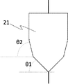
- the portion having the (cone) inverted conical shape may be single (that is, the inclination angle is constant), but a plurality of (cone) inverses like the container 21 in FIG.
- a conical shape (inclination angles different from each other) may be continuously formed vertically.
- the height of the portion where the sectional area of the lumen gradually increases from the bottom to the top is 40 to 100% of the total height of the container 2.
- the inclination angle of the portion where the cross-sectional area of the lumen gradually increases from the bottom to the top is preferably larger than the repose angle of the granular adsorbent in the stationary liquid, and particularly preferably 30 to 85 °.
- the portion other than the portion where the sectional area of the lumen gradually increases as it goes from the bottom to the top has a cylindrical shape.
- the particulate adsorbent is prevented from dropping into the first supply pipe 3 and / or the second discharge pipe 6 in the vicinity of the container installation site in the bottom of the container or in the first supply pipe 3 and / or the second discharge pipe 6. It is preferable to install a filter for this purpose.
- the container 2 can accommodate the granular adsorbent in a flowable state.
- the granular adsorbent flows when a liquid containing an adsorption target substance (hereinafter referred to as a first liquid) is supplied to form a fluidized bed.
- a first liquid a liquid containing an adsorption target substance
- the flow velocity of the first liquid has a gradient that is inversely proportional to the cross-sectional area. Small particles are classified at the top.
- the particulate adsorbent is not particularly limited as long as it can adsorb and desorb a substance to be adsorbed.
- the particulate adsorbent used in the present invention may be one in which an adsorption active component is supported on a solid support, or one containing an adsorption active component.
- the granular adsorbent has a true density of preferably 2 to 5 g / cm 3 , more preferably 3 to 4 g / cm 3 .
- the granular adsorbent has a 50% diameter in a volume-based cumulative particle size distribution, preferably 10 to 2000 ⁇ m, more preferably 50 to 500 ⁇ m.
- the granular adsorbent has a ratio of 90% diameter to 10% diameter in a volume-based cumulative particle size distribution of preferably 1.8 or more, more preferably 1.8 to 5.
- an adsorbent made of an inorganic adsorptive active component that is difficult to produce with uniform particle sizes can be used with high efficiency.
- the first supply pipe is for supplying the first liquid to the container.
- the first supply pipe 3 is installed at the bottom of the container.
- the first liquid may further contain a solid suspended matter as long as the effects of the present invention are not impaired.
- Substances to be adsorbed include phosphorus-containing substances such as phosphoric acid and phosphorous acid; halogen-containing substances such as chlorine and halogenated hydrocarbons; sulfur-containing substances such as sulfuric acid and sulfurous acid; nitrogen-containing substances such as ammonia and amines. be able to.
- the first liquid is supplied to the bottom of the container via the first supply pipe 3, and the liquid to be flowed upward in the container lumen is used to flow at least a part of the granular adsorbent, while the substance to be adsorbed is flown.
- An adsorption process for adsorbing the particulate adsorbent is performed. In this step, it is preferable that 80% by mass or more of the granular adsorbent is flowing. Furthermore, it is preferable that all of the granular adsorbent is flowing without being in a continuous settling state.
- the flow rate of the liquid supplied via the first supply pipe 3 is not particularly limited as long as the granular adsorbent forms a fluidized bed.
- the liquid adsorbed by the particulate adsorbent is discharged from the container 2 through the first discharge pipe 5.
- the first discharge pipe 5 is preferably installed at the top of the container as shown in FIG. 1, but this is not essential, and at least the lumen cross-sectional area gradually increases from the bottom to the top. It only needs to be installed above the part. Since the granular adsorbent forms a fluidized bed below the first discharge pipe 5, the granular adsorbent having the minimum particle size required for the adsorption / desorption method of the present invention is further below the first discharge pipe 5.
- the shape of the container and the installation site of the first discharge pipe 5 may be designed so that the fluidized bed is formed in a portion where the sectional area of the lumen gradually increases from the bottom to the top. Thereby, the unnecessary fine particles derived from the adsorbent are discharged through the first discharge pipe 5 together with the suspended matter that may be contained in the first liquid.
- the second discharge pipe 6 is for discharging liquid from the container.
- the second discharge pipe 6 is installed at the bottom of the container.
- the concentration of the substance to be adsorbed in the liquid flowing through the first discharge pipe 5 is measured.
- the measured value exceeds a predetermined value, for example, when the measured value becomes close to the adsorption target substance concentration in the liquid containing the adsorption target substance supplied from the first supply pipe 3, It means that the amount of the adsorption target substance adsorbed by the granular adsorbent is approaching the saturated adsorption amount.
- the supply of the first liquid from the first supply pipe 3 is stopped, and then the liquid accumulated in the container lumen is discharged from the container bottom via the second discharge pipe 6. Since the discharged liquid has the same composition ratio as the liquid supplied via the first supply pipe 3, it is supplied again via the first supply pipe 3 when the adsorption process is resumed. be able to.
- the granular adsorbent settles to the bottom of the container, but prior to that, the granular adsorbent is classified in the container as described above, Since the granular adsorbent having a small particle size settles in a portion having a larger upper cross-sectional area, it has an effect of reducing pressure loss.
- the second supply pipes 4a and 4b are for supplying a container with a liquid or a regenerating liquid (hereinafter referred to as a second liquid when both are included) for desorbing the adsorption target substance from the granular adsorbent.
- tube is installed in the arbitrary positions of a container, for example, the top part, side part, or bottom part of a container.
- the installation position of the second supply pipe is preferably above the portion where the sectional area of the lumen gradually increases from the bottom to the top, and more preferably at the top.
- the regenerating liquid means a liquid for regenerating the adsorption activity of the granular adsorbent.
- the second supply pipe 4b is installed at the bottom of the container.
- the second supply pipe 4a is installed at the top of the container.
- the apparatus of FIG. 1 is depicted as having both the second supply pipe 4a and the second supply pipe 4b installed, the apparatus of the present invention has only one of them installed. There may be.
- a liquid for desorbing the substance to be adsorbed is supplied to the bottom of the container via the second supply pipe 4b, and the liquid is allowed to flow upward in the container lumen to be granular.
- a desorption step of desorbing the adsorption target substance from the granular adsorbent while flowing at least a part of the adsorbent can be performed. In this step, it is preferable that 80% by mass or more of the granular adsorbent is flowing. Furthermore, it is preferable that all of the granular adsorbent is flowing without being in a continuous settling state.
- the flow rate of the liquid supplied via the second supply pipe 4b is not particularly limited as long as the granular adsorbent forms a fluidized bed.
- the desorbed liquid is discharged from the container 2 through the first discharge pipe 5.
- the desorbed liquid contains the substance to be adsorbed.
- the liquid discharged through the first discharge pipe 5 may be supplied to the second supply pipe 4b and circulated.
- the first discharge pipe 5 and the second supply pipe 4b are connected, and the liquid discharged through the first discharge pipe 5 is directly supplied to the second supply pipe 4b and circulated for a predetermined time.
- the concentration of the substance to be adsorbed in the liquid flowing through the first discharge pipe 5 is measured.
- the measured value falls below a predetermined value, for example, when the measured value approaches zero, the amount of the adsorption target substance that can be desorbed from the granular adsorbent is approaching zero.
- the supply of the liquid for desorbing the substance to be adsorbed from the second supply pipe 4 b is stopped, and then the liquid accumulated in the container lumen is discharged from the container bottom via the second discharge pipe 6.
- a liquid for desorbing the adsorption target substance is supplied to the top of the container via the second supply pipe 4a, and the liquid is stored in the container lumen to be adsorbed target substance.
- a desorption step of desorbing from the particulate adsorbent can be performed.
- the liquid for desorbing the adsorption target substance to be supplied via the second supply pipe 4a may be stopped when (1) the granular adsorbent in the container lumen is completely immersed in the liquid. And (2) the supply may be stopped when the container lumen is completely filled, or (3) the second supply pipe 6 is connected to the second supply tube after the container lumen is completely filled.
- Supply may be continued while discharging in an amount commensurate with the supply amount via 4a.
- the liquid discharged through the second discharge pipe 6 may be supplied to the second supply pipe 4a and circulated.
- the second discharge pipe 6 and the second supply pipe 4a are connected, and the liquid discharged through the second discharge pipe 6 is directly supplied to the second supply pipe 4a and circulated for a certain period of time.
- a method in which the step of storing the liquid discharged through the second discharge pipe 6 in the tank and the step of supplying the liquid from the tank to the second supply pipe 4a are repeated a certain number of times. Is done.
- the desorbed liquid is discharged from the container 2 through the second discharge pipe 6.
- the concentration of the substance to be adsorbed in the liquid flowing through the second discharge pipe 6 is measured.
- the measured value falls below a predetermined value, for example, when the measured value approaches zero, the amount of the adsorption target substance that can be desorbed from the granular adsorbent is approaching zero. Means that. Therefore, in the present invention, the supply of the liquid for desorbing the substance to be adsorbed from the second supply pipe 4 a is stopped, and then the liquid accumulated in the container lumen is discharged from the container bottom via the second discharge pipe 6.
- the desorbed liquid contains the substance to be adsorbed.
- the saturated adsorption amount of the granular adsorbent decreases or the amount of the adsorption target substance that can be desorbed from the granular adsorbent decreases.
- the granular adsorbent can be regenerated.
- regeneration may be essential for reuse after desorption.
- the regeneration liquid is supplied to the bottom of the container via the second supply pipe 4b, and the resorption liquid is flowed upward in the container lumen to cause at least a part of the granular adsorbent to flow, thereby increasing the adsorption activity of the granular adsorbent.
- it is preferable that all of the granular adsorbent is flowing without being in a continuous settling state.
- the regeneration liquid can be supplied to the top of the container via the second supply pipe 4a, and the regeneration liquid can be stored in the container lumen to regenerate the adsorption activity of the granular adsorbent.
- the above-described adsorption process, discharge process, desorption process, and regeneration process can be switched by manually or automatically operating the valves (v1 to v5) and the pump.
- the adsorption / desorption device of the present invention has control means for automatically operating valves and pumps.
- the control means can include means for measuring the concentration of the substance to be adsorbed, means for comparing the measured value with a predetermined value, and the like.
- the first liquid is supplied to the container through the first supply pipe, and the substance to be adsorbed is granularly adsorbed while flowing at least a part of the granular adsorbent by flowing the first liquid upward in the container lumen.
- Adsorption mode for adsorbing to the material and discharging the liquid from the first discharge pipe, first extraction mode for stopping the supply of the first liquid through the first supply pipe and discharging the liquid from the container through the second discharge pipe
- a desorption mode in which the second liquid is supplied to the container via the second supply pipe, the adsorption target substance is desorbed from the particulate adsorbent, and the liquid is discharged from the first discharge pipe or the second discharge pipe, and the second supply pipe It is possible to perform the second extraction mode in which the supply of the second liquid is stopped and the liquid is discharged from the container through the second discharge pipe.
- the adsorption mode it is preferable that 80% by mass or more of the granular adsorbent is flowing.
- control means can supply a regenerating liquid to the container through the second supply pipe as necessary to perform a regeneration mode for regenerating the granular adsorbent.
- Adsorption / desorption device 2 Container 21: Container 3: First supply pipe 4a, 4b: Second supply pipe 5: First discharge pipe 6: Second discharge pipe v1, v2, v3, v4, v5: Valve ⁇ , ⁇ 1, ⁇ 2: container inclination angle
Landscapes
- Chemical & Material Sciences (AREA)
- Analytical Chemistry (AREA)
- Chemical Kinetics & Catalysis (AREA)
- Organic Chemistry (AREA)
- Treatment Of Liquids With Adsorbents In General (AREA)
- Water Treatment By Sorption (AREA)
Abstract
本発明の課題は、液相における吸着および脱着の効率が高い吸脱着方法およびその方法を実施するための吸脱着装置を提供することである。 本発明の吸脱着方法は、流動可能な状態で粒状吸着材が収容され且つ内腔の断面積が下から上に向かうにつれて漸次大きくなる部分を少なくとも下部に有する容器において、吸着対象物質を含有する液体を容器底部に供給し、容器内腔で上向きに前記液体を流して粒状吸着材の少なくとも一部を流動させながら吸着対象物質を粒状吸着材に吸着させる吸着工程、吸着対象物質を含有する液体の供給を停止し、次いで容器底部から容器内腔に溜まった液体を排出する工程、粒状吸着材から吸着対象物質を脱着させるための液体を容器に供給して吸着対象物質を粒状吸着材から脱着させる脱着工程、および粒状吸着材から吸着対象物質を脱着させるための液体の供給を停止し、次いで容器底部から容器内腔に溜まった液体を排出する工程を含む。
Description
本発明は、吸脱着方法及び吸脱着装置に関する。より詳細に、液相における吸着および脱着の効率が高い吸脱着方法およびその方法を実施するための吸脱着装置に関する。本願は、2017年2月9日に出願された日本国特許出願第2017-22572号に対し優先権を主張し、その内容をここに援用する。
液相吸着方法が従来から種々知られている。例えば、特許文献1は、フッ素またはリン酸吸着剤が充填された反応槽に、フッ素および/またはリン酸を含有する排水を通液し、該反応槽内で前記排水を吸着して、フッ素および/またはリン酸が低減された水を生じさせる吸着工程、前記吸着工程後のフッ素またはリン酸吸着剤が充填された反応槽に、再生剤を循環的に通液する再生工程、および再生工程後のフッ素またはリン酸吸着剤が充填された反応槽に、活性化剤を通液する活性化工程を含む、フッ素またはリン酸吸着剤の再生方法において、吸着工程および/活性化工程における通液が上向流で流動床の態様で行われる、前記フッ素またはリン酸吸着剤の再生方法を開示している。
特許文献2は、吸着剤と、前記吸着剤の粒子を可動自在に収容した吸着容器と、前記吸着剤が流動するように前記吸着容器へ流体を流入させる輸送手段とからなり、前記吸着容器が、容器底部の形状が錐形あるいは容器底部の断面積が容器部分の断面積よりも小さい形状である、吸着装置を開示している。
非特許文献1は、流動層による吸着・脱着の繰り返し実験を開示している。該実験は具体的に次のようにして行ったと非特許文献1は述べている。ペクチン酸をジルコニウムに担持してなる吸着剤を膨潤させ、反応器に充填した。pH2.0に調整したリン含有排水を反応器に通液させて吸着を行った。その後、反応器内の液のみを抜き取った。次に0.2MNaOHを反応器に通液させて脱着を行った。その後、反応器内の液のみを抜き取った。吸着剤のコンディショニングを行い、再び吸着及び脱着を繰り返し行った。
非特許文献2は、粒径分布を有する活性炭を用いた場合、流動層法の効率が、均一粒径の活性炭を用いた場合に比べて、著しく改善されると述べている。
原田浩幸ら「ミカン搾汁残渣を有効利用したリンの回収方法」平成20~21年度循環型社会形成推進科学研究費補助金事業 総合研究報告書pp38-39
湯浅 晶ら「粒径分布をもつ活性炭を用いた固定層吸着と流動層吸着の効率比較実験」土木学会中部支部研究発表会講演概要集、1987年、214-215頁
本発明の課題は、液相における吸着および脱着の効率が高い吸脱着方法およびその方法を実施するための吸脱着装置を提供することである。
上記課題を解決すべく鋭意検討した結果、以下の形態を包含する本発明を完成するに至った。
すなわち、本発明は、以下のとおりのものである。
〔1〕 流動可能な状態で粒状吸着材が収容され且つ内腔の断面積が下から上に向かうにつれて漸次大きくなる部分を少なくとも下部に有する容器において、
吸着対象物質を含有する液体を容器底部に供給し、容器内腔で上向きに前記液体を流して粒状吸着材の少なくとも一部を流動させながら吸着対象物質を粒状吸着材に吸着させる吸着工程、
吸着対象物質を含有する液体の供給を停止し、次いで容器底部から容器内腔に溜まった液体を排出する工程、
粒状吸着材から吸着対象物質を脱着させるための液体を容器に供給して吸着対象物質を粒状吸着材から脱着させる脱着工程、および
粒状吸着材から吸着対象物質を脱着させるための液体の供給を停止し、次いで容器底部から容器内腔に溜まった液体を排出する工程、
を含む、吸脱着方法。
吸着対象物質を含有する液体を容器底部に供給し、容器内腔で上向きに前記液体を流して粒状吸着材の少なくとも一部を流動させながら吸着対象物質を粒状吸着材に吸着させる吸着工程、
吸着対象物質を含有する液体の供給を停止し、次いで容器底部から容器内腔に溜まった液体を排出する工程、
粒状吸着材から吸着対象物質を脱着させるための液体を容器に供給して吸着対象物質を粒状吸着材から脱着させる脱着工程、および
粒状吸着材から吸着対象物質を脱着させるための液体の供給を停止し、次いで容器底部から容器内腔に溜まった液体を排出する工程、
を含む、吸脱着方法。
〔2〕 再生液を容器に供給して粒状吸着材の吸着活性を再生させる再生工程をさらに含む、〔1〕に記載の吸脱着方法。
〔3〕 脱着工程が、
粒状吸着材から吸着対象物質を脱着させるための液体を容器底部に供給し、容器内腔で上向きに前記液体を流して粒状吸着材の少なくとも一部を流動させながら吸着対象物質を粒状吸着材から脱着させることを含む、〔1〕または〔2〕に記載の吸脱着方法。
〔4〕 再生工程が、
再生液を容器底部に供給し、容器内腔で上向きに再生液を流して粒状吸着材の少なくとも一部を流動させながら粒状吸着材の吸着活性を再生させることを含む、〔2〕に記載の吸脱着方法。
〔5〕 粒状吸着材は、体積基準累積粒度分布において、50%径が10~2000μmで、10%径に対する90%径の比が1.8以上である、〔1〕~〔4〕のいずれかひとつに記載の吸脱着方法。
〔6〕 粒状吸着材は、真密度が2~5g/cm3である、〔1〕~〔5〕のいずれかひとつに記載の吸脱着方法。
〔3〕 脱着工程が、
粒状吸着材から吸着対象物質を脱着させるための液体を容器底部に供給し、容器内腔で上向きに前記液体を流して粒状吸着材の少なくとも一部を流動させながら吸着対象物質を粒状吸着材から脱着させることを含む、〔1〕または〔2〕に記載の吸脱着方法。
〔4〕 再生工程が、
再生液を容器底部に供給し、容器内腔で上向きに再生液を流して粒状吸着材の少なくとも一部を流動させながら粒状吸着材の吸着活性を再生させることを含む、〔2〕に記載の吸脱着方法。
〔5〕 粒状吸着材は、体積基準累積粒度分布において、50%径が10~2000μmで、10%径に対する90%径の比が1.8以上である、〔1〕~〔4〕のいずれかひとつに記載の吸脱着方法。
〔6〕 粒状吸着材は、真密度が2~5g/cm3である、〔1〕~〔5〕のいずれかひとつに記載の吸脱着方法。
〔7〕 流動可能な状態で粒状吸着材を収容でき且つ内腔の断面積が下から上に向かうにつれて漸次大きくなる部分を少なくとも下部に有する容器;
吸着対象物質を含有する液体を容器に供給するための第一供給管;
粒状吸着材から吸着対象物質を脱着させるための液体又は再生液を容器に供給するための第二供給管;
容器から液体を排出するための第一排出管;
容器から液体を排出するための第二排出管; ならびに
第一供給管を経て吸着対象物質を含有する液体を容器に供給して、容器内腔で上向きに吸着対象物質を含有する液体を流して粒状吸着材の少なくとも一部を流動させながら吸着対象物質を粒状吸着材に吸着させ、第一排出管から液体を排出する吸着モード、
第一供給管を経ての吸着対象物質を含有する液体の供給を停止させ、第二排出管を経て容器から液体を排出させる第一抜出モード、
第二供給管を経て粒状吸着材から吸着対象物質を脱着させるための液体又は再生液を容器に供給して、吸着対象物質を粒状吸着材から脱着させ、第一排出管又は第二排出管から液体を排出する脱着モード、および
第二供給管を経ての粒状吸着材から吸着対象物質を脱着させるための液体又は再生液の供給を停止させ、第二排出管を経て容器から液体を排出させる第二抜出モードを、行うようにするための制御手段を有する、
吸脱着装置。
吸着対象物質を含有する液体を容器に供給するための第一供給管;
粒状吸着材から吸着対象物質を脱着させるための液体又は再生液を容器に供給するための第二供給管;
容器から液体を排出するための第一排出管;
容器から液体を排出するための第二排出管; ならびに
第一供給管を経て吸着対象物質を含有する液体を容器に供給して、容器内腔で上向きに吸着対象物質を含有する液体を流して粒状吸着材の少なくとも一部を流動させながら吸着対象物質を粒状吸着材に吸着させ、第一排出管から液体を排出する吸着モード、
第一供給管を経ての吸着対象物質を含有する液体の供給を停止させ、第二排出管を経て容器から液体を排出させる第一抜出モード、
第二供給管を経て粒状吸着材から吸着対象物質を脱着させるための液体又は再生液を容器に供給して、吸着対象物質を粒状吸着材から脱着させ、第一排出管又は第二排出管から液体を排出する脱着モード、および
第二供給管を経ての粒状吸着材から吸着対象物質を脱着させるための液体又は再生液の供給を停止させ、第二排出管を経て容器から液体を排出させる第二抜出モードを、行うようにするための制御手段を有する、
吸脱着装置。
〔8〕 第一供給管の設置位置が、容器の底部である、〔7〕に記載の吸脱着装置。
〔9〕 第一排出管の設置位置が、容器の、内腔の断面積が下から上に向かうにつれて漸次大きくなる部分より上である、〔7〕に記載の吸脱着装置。
〔10〕 第二供給管の設置位置が、容器の、内腔の断面積が下から上に向かうにつれて漸次大きくなる部分より上である、〔7〕に記載の吸脱着装置。
〔11〕 第二供給管の設置位置が、容器の底部である、〔7〕に記載の吸脱着装置。
〔12〕 第二排出管の設置位置が、容器の底部である、〔7〕に記載の吸脱着装置。
〔13〕 内腔各部の水平断面が円形である、〔7〕に記載の吸脱着装置。
〔14〕 内腔の断面積が下から上に向かうにつれて漸次大きくなる部分は、傾斜角が30~85°、高さが容器全高に対して40~100%である、〔7〕~〔13〕のいずれかひとつに記載の吸脱着装置。
〔15〕 粒状吸着材は、体積基準累積粒度分布において、50%径が10~2000μmで、10%径に対する90%径の比が1.8以上である、〔7〕~〔14〕のいずれかひとつに記載の吸脱着装置。
〔16〕 粒状吸着材は、真密度が2~5g/cm3である、〔7〕~〔15〕のいずれかひとつに記載の吸脱着装置。
〔9〕 第一排出管の設置位置が、容器の、内腔の断面積が下から上に向かうにつれて漸次大きくなる部分より上である、〔7〕に記載の吸脱着装置。
〔10〕 第二供給管の設置位置が、容器の、内腔の断面積が下から上に向かうにつれて漸次大きくなる部分より上である、〔7〕に記載の吸脱着装置。
〔11〕 第二供給管の設置位置が、容器の底部である、〔7〕に記載の吸脱着装置。
〔12〕 第二排出管の設置位置が、容器の底部である、〔7〕に記載の吸脱着装置。
〔13〕 内腔各部の水平断面が円形である、〔7〕に記載の吸脱着装置。
〔14〕 内腔の断面積が下から上に向かうにつれて漸次大きくなる部分は、傾斜角が30~85°、高さが容器全高に対して40~100%である、〔7〕~〔13〕のいずれかひとつに記載の吸脱着装置。
〔15〕 粒状吸着材は、体積基準累積粒度分布において、50%径が10~2000μmで、10%径に対する90%径の比が1.8以上である、〔7〕~〔14〕のいずれかひとつに記載の吸脱着装置。
〔16〕 粒状吸着材は、真密度が2~5g/cm3である、〔7〕~〔15〕のいずれかひとつに記載の吸脱着装置。
本発明の吸脱着方法および吸脱着装置は、液相における吸着および脱着の効率が高い。特に真密度が高く広い粒径分布を有する吸着材を用いた場合に吸着および脱着の効率が高い。
図面を参照しながら本発明の実施形態を説明する。
本発明の吸脱着装置は、容器2、第一供給管3、第二供給管4a,4b、第一排出管5、第二排出管6、ならびに制御手段を有する。
本発明の吸脱着装置は、容器2、第一供給管3、第二供給管4a,4b、第一排出管5、第二排出管6、ならびに制御手段を有する。
容器2は、内腔の断面積が下から上に向かうにつれて漸次大きくなる部分を少なくとも下部に有する。この部分における傾斜角は、一定であってもよいし、上下方向に連続的または不連続に変化していてもよい。容器2の内腔各部の水平断面は円形であることが好ましい。好ましくは下部に逆円錐形状または截頭逆円錐形状を成している部分を有する。この(截頭)逆円錐形状を成している部分は、単一(すなわち傾斜角が一定である。)であってもよいが、図2の容器21のように複数の(截頭)逆円錐形状(互いに傾斜角が異なる。)が上下に連続して成っていてもよい。
内腔の断面積が下から上に向かうにつれて漸次大きくなる部分の高さは、容器2の全高の40~100%であることが好ましい。内腔の断面積が下から上に向かうにつれて漸次大きくなる部分の傾斜角は、静止液体中における粒状吸着材の安息角より大きいことが好ましく、特に30~85°であることが好ましい。
内腔の断面積が下から上に向かうにつれて漸次大きくなる部分以外の部分は円筒形状を成していることが好ましい。
容器底部、または第一供給管3内および/または第二排出管6内の容器設置部位近傍には、第一供給管3および/または第二排出管6への粒状吸着材の落下を防止するためのフィルターを設置するのが好ましい。
容器2には、流動可能な状態で粒状吸着材を収容できる。粒状吸着材は、吸着対象物質を含有する液体(以下、第一液体という)を供給したときに流動して、流動層を形成する。
内腔の断面積が下から上に向かうにつれて漸次大きくなる部分で、第一液体の流速には断面積に反比例した勾配が生じ、これにより粒状吸着材は、大粒径のものが下部に、小粒径のものが上部に分級される。従って、吸着対象物質は、大粒径の粒状吸着材に多くが吸着された後、残りが高い吸着速度を示す小粒径の粒状吸着材に吸着され、結果的に高い吸着効率が達成される。
内腔の断面積が下から上に向かうにつれて漸次大きくなる部分で、第一液体の流速には断面積に反比例した勾配が生じ、これにより粒状吸着材は、大粒径のものが下部に、小粒径のものが上部に分級される。従って、吸着対象物質は、大粒径の粒状吸着材に多くが吸着された後、残りが高い吸着速度を示す小粒径の粒状吸着材に吸着され、結果的に高い吸着効率が達成される。
粒状吸着材は、吸着対象物質を吸脱着できるものであれば特に制限されない。例えば、活性炭、シリカゲル、活性アルミナ、シリカ-アルミナ、ゼオライト;鉄、ジルコニウム等の金属の酸化物、水酸化物又は酸化水酸化物からなる吸着材;非特許文献1に記載の吸着剤などを挙げることができる。本発明に用いられる粒状吸着材は、吸着活性成分を固体担体に担持させたもの、吸着活性成分を含有するものなどであってもよい。
粒状吸着材は、真密度が、好ましくは2~5g/cm3、より好ましくは3~4g/cm3である。粒状吸着材の真密度と第一液体との差が大きい方が、上述の分級効果が大きく現れるが、流動層を容易に形成させるために真密度を上記範囲とすることが好ましい。
粒状吸着材は、体積基準累積粒度分布において、50%径が、好ましくは10~2000μm、より好ましくは50~500μmである。粒状吸着材は、体積基準累積粒度分布において、10%径に対する90%径の比が、好ましくは1.8以上、より好ましくは1.8~5である。本発明により、特に、粒度を揃えて製造することが困難な無機系吸着活性成分からなる吸着材を高効率で使用することができる。
第一供給管は第一液体を容器に供給するためのものである。図1に示される装置において、第一供給管3は、容器の底部に設置されている。第一液体は、本発明の効果を阻害しない限り、さらに固形浮遊物を含有してもよい。吸着対象物質としては、リン酸、亜リン酸などのリン含有物質;塩素、ハロゲン化炭化水素などのハロゲン含有物質;硫酸、亜硫酸などの硫黄含有物質;アンモニア、アミンなどの窒素含有物質などを挙げることができる。本発明においては第一供給管3を経由して、第一液体を容器底部に供給し、容器内腔で上向きに前記液体を流して粒状吸着材の少なくとも一部を流動させながら吸着対象物質を粒状吸着材に吸着させる吸着工程を行う。本工程では、粒状吸着材の80質量%以上が流動していることが好ましい。さらに前記粒状吸着材の全部が、継続的な沈殿状態にあることなく、流動していることが好ましい。第一供給管3を経由して供給される液体の流量は、粒状吸着材が流動層を形成する限り特に限定されない。粒状吸着材による吸着が為された液体は、容器2から第一排出管5を経て排出される。
第一排出管5は、図1に示される通り、容器の頂部に設置されていることが好ましいが、このことは必須ではなく、少なくとも内腔の断面積が下から上に向かうにつれて漸次大きくなる部分より上に設置されていればよい。粒状吸着材は第一排出管5より下で流動層を形成するので、本発明の吸脱着方法に必要とされる最小粒径を有する粒状吸着材が、第一排出管5より下に、より好ましくは内腔の断面積が下から上に向かうにつれて漸次大きくなる部分に、流動層を形成するように、容器の形状及び第一排出管5の設置部位を設計すればよい。これにより、吸着材に由来する不要の微粒子は、第一液体に含有されていてもよい浮遊物とともに、第一排出管5を通じて排出される。
第二排出管6は容器から液体を排出するためのものである。図1に示される装置において、第二排出管6は、容器の底部に設置されている。前述の吸着工程において、第一排出管5を流れる液体中の吸着対象物質濃度を測定する。その測定値が、所定の値を超えたとき、例えば、測定値が第一供給管3から供給される吸着対象物質を含有する液体中の吸着対象物質濃度に接近した値になってきたとき、粒状吸着材によって吸着された吸着対象物質の量が飽和吸着量に近づいていることを意味する。そこで、本発明では、第一供給管3からの第一液体の供給を停止し、次いで容器底部から容器内腔に溜まった液体を第二排出管6経由で排出する。排出された液体は、第一供給管3経由で供給された液と同程度の組成比を有するものであるので、吸着工程が再開されたときに、再度、第一供給管3経由で供給することができる。
容器内腔に溜まった液体を第二排出管6経由で排出する際には、粒状吸着材は容器底部に沈降するが、それに先立ち上述のように粒状吸着材が容器内で分級されており、小粒径の粒状吸着材は、より上方の断面積が大きい部分に沈降するため、圧力損失を低減する効果がある。
第二供給管4a,4bは、粒状吸着材から吸着対象物質を脱着させるための液体又は再生液(以下、両者を包含する場合は第二液体という)を容器に供給するためのものである。第二供給管は、容器の任意位置に、例えば、容器の頂部、側部若しくは底部に、設置される。第二供給管の設置位置は、内腔の断面積が下から上に向かうにつれて漸次大きくなる部分より上であることが好ましく、頂部であることがより好ましい。なお、再生液とは、粒状吸着材の吸着活性を再生させるための液体を意味する。
第二供給管4bは、容器の底部に設置されている。第二供給管4aは、容器の頂部に設置されている。図1の装置には、第二供給管4aと第二供給管4bとが両方設置されているように描かれているが、本発明の装置は、どちらか一方だけが設置されているものであってもよい。
第二供給管4bを設置した場合、例えば、第二供給管4bを経由して、吸着対象物質を脱着させるための液体を容器底部に供給し、容器内腔で上向きに前記液体を流して粒状吸着材の少なくとも一部を流動させながら吸着対象物質を粒状吸着材から脱着させる脱着工程を行うことができる。本工程では、粒状吸着材の80質量%以上が流動していることが好ましい。さらに粒状吸着材の全部が、継続的な沈殿状態にあることなく、流動していることが好ましい。第二供給管4bを経由して供給される液体の流量は、粒状吸着材が流動層を形成する限り特に限定されない。脱着が為された液体は、容器2から第一排出管5を経て排出される。脱着が為された液体には吸着対象物質が含まれている。
また、必要であれば、第一排出管5を経て排出された液体を第二供給管4bに供給して循環させてもよい。そのための具体的な方法としては、第一排出管5と第二供給管4bとを接続し、第一排出管5を経て排出された液体を第二供給管4bに直接供給して一定時間循環させる方法;第一排出管5を経て排出された液体をタンクに貯留する工程と、その後該タンク内から液体を第二供給管4bに供給する工程とを、一定回数反復する方法;等が例示される。この場合は、第一排出管5を流れる液体中の吸着対象物質濃度が所定の値に達したとき、循環を停止し、第一排出管5を流れる液体を回収する。
前述の脱着工程において、第一排出管5を流れる液体中の吸着対象物質濃度を測定する。その測定値が、所定の値を下回ったとき、例えば、測定値が、ゼロに接近した値になってきたとき、粒状吸着材から脱着させることができる吸着対象物質の量がゼロに近づいていることを意味する。そこで、本発明では、第二供給管4bからの吸着対象物質を脱着させるための液体の供給を停止し、次いで容器底部から容器内腔に溜まった液体を第二排出管6経由で排出する。
第二供給管4aを設置した場合、例えば、第二供給管4aを経由して、吸着対象物質を脱着させるための液体を容器頂部に供給し、容器内腔に前記液体を溜めて吸着対象物質を粒状吸着材から脱着させる脱着工程を行うことができる。第二供給管4aを経由して供給する吸着対象物質を脱着させるための液体は、(1)容器内腔中の粒状吸着材が完全に液中に浸ったときに供給を停止してもよいし、(2)容器内腔が完全に満たされたときに供給を停止してもよいし、または(3)容器内腔が完全に満たされた後も第二排出管6から第二供給管4a経由の供給量に見合った量で排出しながら供給を継続してもよい。(3)においては、さらに(4)第二排出管6を経て排出された液体を第二供給管4aに供給して循環させてもよい。そのための具体的な方法としては、第二排出管6と第二供給管4aとを接続し、第二排出管6を経て排出された液体を第二供給管4aに直接供給して一定時間循環させる方法;第二排出管6を経て排出された液体をタンクに貯留する工程と、その後該タンク内から液体を第二供給管4aに供給する工程とを、一定回数反復する方法;等が例示される。(1)若しくは(2)によって脱着を行った場合は、脱着が為された液体を容器2から第二排出管6を経て排出する。(3)によって脱着を行った場合は、第二排出管6を流れる液体中の吸着対象物質濃度を測定する。その測定値が、所定の値を下回ったとき、例えば、測定値が、ゼロに接近した値になってきたとき、粒状吸着材から脱着させることができる吸着対象物質の量がゼロに近づいていることを意味する。そこで、本発明では、第二供給管4aからの吸着対象物質を脱着させるための液体の供給を停止し、次いで容器底部から容器内腔に溜まった液体を第二排出管6経由で排出する。(4)によって脱着を行った場合は、第二排出管6を流れる液体中の吸着対象物質濃度が所定の値に達したとき、循環を停止し、第二排出管6を流れる液体を回収する。脱着が為された液体には吸着対象物質が含まれている。
上記のような吸着および脱着を複数回繰り返すと、粒状吸着材の飽和吸着量が低下したり、粒状吸着材から脱着させることができる吸着対象物質の量が減少したりする。そのような状態になったときには、粒状吸着材の再生を行うことができる。また粒状吸着材と吸着対象物質の種類によっては、脱着後の再使用には再生が必須であることもある。例えば、第二供給管4bを経由して、再生液を容器底部に供給し、容器内腔で上向きに再生液を流して粒状吸着材の少なくとも一部を流動させながら粒状吸着材の吸着活性を再生させることができる。この場合には、粒状吸着材の80質量%以上が流動していることが好ましい。さらに粒状吸着材の全部が、継続的な沈殿状態にあることなく、流動していることが好ましい。また、第二供給管4aを経由して、再生液を容器頂部に供給し、容器内腔に再生液を溜めて粒状吸着材の吸着活性を再生させることができる。
上記の、吸着工程、排出工程、脱着工程、および再生工程を、バルブ(v1~v5)およびポンプを手動または自動で操作することによって、切り替えることができる。本発明の吸脱着装置には、バルブおよびポンプなどを自動で操作するための制御手段を有する。制御手段には吸着対象物質の濃度を測定するための手段、測定値と所定値とを比較する手段などを有することができる。該制御手段によって、第一供給管を経て第一液体を容器に供給して、容器内腔で上向きに第一液体を流して粒状吸着材の少なくとも一部を流動させながら吸着対象物質を粒状吸着材に吸着させ、第一排出管から液体を排出する吸着モード、第一供給管を経ての第一液体の供給を停止させ、第二排出管を経て容器から液体を排出させる第一抜出モード、第二供給管を経て第二液体を容器に供給して、吸着対象物質を粒状吸着材から脱着させ第一排出管又は第二排出管から液体を排出する脱着モード、および第二供給管を経ての第二液体の供給を停止させ、第二排出管を経て容器から液体を排出させる第二抜出モードを、行うようにすることができる。吸着モードでは、粒状吸着材の80質量%以上が流動していることが好ましい。さらに粒状吸着材の全部が、継続的な沈殿状態にあることなく、流動していることが好ましい。特に上記各モードを、上記の順で順次行うことが好ましい。さらに該制御手段によって、必要に応じて第二供給管を経て再生液を容器に供給して、粒状吸着材を再生する再生モードを行うようにすることができる。
1:吸脱着装置
2:容器
21:容器
3:第一供給管
4a、4b:第二供給管
5:第一排出管
6:第二排出管
v1、v2、v3、v4、v5:バルブ
θ、θ1、θ2:容器の傾斜角
2:容器
21:容器
3:第一供給管
4a、4b:第二供給管
5:第一排出管
6:第二排出管
v1、v2、v3、v4、v5:バルブ
θ、θ1、θ2:容器の傾斜角
Claims (16)
- 流動可能な状態で粒状吸着材が収容され且つ内腔の断面積が下から上に向かうにつれて漸次大きくなる部分を少なくとも下部に有する容器において、
吸着対象物質を含有する液体を容器底部に供給し、容器内腔で上向きに前記液体を流して粒状吸着材の少なくとも一部を流動させながら吸着対象物質を粒状吸着材に吸着させる吸着工程、
吸着対象物質を含有する液体の供給を停止し、次いで容器底部から容器内腔に溜まった液体を排出する工程、
粒状吸着材から吸着対象物質を脱着させるための液体を容器に供給して吸着対象物質を粒状吸着材から脱着させる脱着工程、および
粒状吸着材から吸着対象物質を脱着させるための液体の供給を停止し、次いで容器底部から容器内腔に溜まった液体を排出する工程、
を含む、吸脱着方法。 - 再生液を容器に供給して粒状吸着材の吸着活性を再生させる再生工程をさらに含む、請求項1に記載の吸脱着方法。
- 脱着工程が、
粒状吸着材から吸着対象物質を脱着させるための液体を容器底部に供給し、容器内腔で上向きに前記液体を流して粒状吸着材の少なくとも一部を流動させながら吸着対象物質を粒状吸着材から脱着させることを含む、請求項1または2に記載の吸脱着方法。 - 再生工程が、
再生液を容器底部に供給し、容器内腔で上向きに再生液を流して粒状吸着材の少なくとも一部を流動させながら粒状吸着材の吸着活性を再生させることを含む、請求項2に記載の吸脱着方法。 - 粒状吸着材は、体積基準累積粒度分布において、50%径が10~2000μmで、10%径に対する90%径の比が1.8以上である、請求項1~4のいずれかひとつに記載の吸脱着方法。
- 粒状吸着材は、真密度が2~5g/cm3である、請求項1~5のいずれかひとつに記載の吸脱着方法。
- 流動可能な状態で粒状吸着材を収容でき且つ内腔の断面積が下から上に向かうにつれて漸次大きくなる部分を少なくとも下部に有する容器;
吸着対象物質を含有する液体を容器に供給するための第一供給管;
粒状吸着材から吸着対象物質を脱着させるための液体又は再生液を容器に供給するための第二供給管;
容器から液体を排出するための第一排出管;
容器から液体を排出するための第二排出管; ならびに
第一供給管を経て吸着対象物質を含有する液体を容器に供給して、容器内腔で上向きに吸着対象物質を含有する液体を流して粒状吸着材の少なくとも一部を流動させながら吸着対象物質を粒状吸着材に吸着させ、第一排出管から液体を排出する吸着モード、
第一供給管を経ての吸着対象物質を含有する液体の供給を停止させ、第二排出管を経て容器から液体を排出させる第一抜出モード、
第二供給管を経て粒状吸着材から吸着対象物質を脱着させるための液体又は再生液を容器に供給して、吸着対象物質を粒状吸着材から脱着させ、第一排出管又は第二排出管から液体を排出する脱着モード、および
第二供給管を経ての粒状吸着材から吸着対象物質を脱着させるための液体又は再生液の供給を停止させ、第二排出管を経て容器から液体を排出させる第二抜出モードを、行うようにするための制御手段を有する、吸脱着装置。 - 第一供給管の設置位置が、容器の底部である、請求項7に記載の吸脱着装置。
- 第一排出管の設置位置が、容器の、内腔の断面積が下から上に向かうにつれて漸次大きくなる部分より上である、請求項7に記載の吸脱着装置。
- 第二供給管の設置位置が、容器の、内腔の断面積が下から上に向かうにつれて漸次大きくなる部分より上である、請求項7に記載の吸脱着装置。
- 第二供給管の設置位置が、容器の底部である、請求項7に記載の吸脱着装置。
- 第二排出管の設置位置が、容器の底部である、請求項7に記載の吸脱着装置。
- 内腔各部の水平断面が円形である、請求項7に記載の吸脱着装置。
- 内腔の断面積が下から上に向かうにつれて漸次大きくなる部分は、傾斜角が30~85°、高さが容器全高に対して40~100%である、請求項7~13のいずれかひとつに記載の吸脱着装置。
- 粒状吸着材は、体積基準累積粒度分布において、50%径が10~2000μmで、10%径に対する90%径の比が1.8以上である、請求項7~14のいずれかひとつに記載の吸脱着装置。
- 粒状吸着材は、真密度が2~5g/cm3である、請求項7~15のいずれかひとつに記載の吸脱着装置。
Priority Applications (1)
| Application Number | Priority Date | Filing Date | Title |
|---|---|---|---|
| JP2018567451A JP6768849B2 (ja) | 2017-02-09 | 2018-02-07 | 吸脱着方法及び吸脱着装置 |
Applications Claiming Priority (2)
| Application Number | Priority Date | Filing Date | Title |
|---|---|---|---|
| JP2017-022572 | 2017-02-09 | ||
| JP2017022572 | 2017-02-09 |
Publications (1)
| Publication Number | Publication Date |
|---|---|
| WO2018147303A1 true WO2018147303A1 (ja) | 2018-08-16 |
Family
ID=63107565
Family Applications (1)
| Application Number | Title | Priority Date | Filing Date |
|---|---|---|---|
| PCT/JP2018/004114 Ceased WO2018147303A1 (ja) | 2017-02-09 | 2018-02-07 | 吸脱着方法及び吸脱着装置 |
Country Status (2)
| Country | Link |
|---|---|
| JP (1) | JP6768849B2 (ja) |
| WO (1) | WO2018147303A1 (ja) |
Citations (3)
| Publication number | Priority date | Publication date | Assignee | Title |
|---|---|---|---|---|
| JPS4834794A (ja) * | 1971-09-08 | 1973-05-22 | ||
| JPS5159072A (ja) * | 1974-11-20 | 1976-05-22 | Kubota Ltd | |
| JP2005144370A (ja) * | 2003-11-17 | 2005-06-09 | Japan Organo Co Ltd | フッ素またはリン酸吸着剤の再生方法 |
-
2018
- 2018-02-07 WO PCT/JP2018/004114 patent/WO2018147303A1/ja not_active Ceased
- 2018-02-07 JP JP2018567451A patent/JP6768849B2/ja active Active
Patent Citations (3)
| Publication number | Priority date | Publication date | Assignee | Title |
|---|---|---|---|---|
| JPS4834794A (ja) * | 1971-09-08 | 1973-05-22 | ||
| JPS5159072A (ja) * | 1974-11-20 | 1976-05-22 | Kubota Ltd | |
| JP2005144370A (ja) * | 2003-11-17 | 2005-06-09 | Japan Organo Co Ltd | フッ素またはリン酸吸着剤の再生方法 |
Also Published As
| Publication number | Publication date |
|---|---|
| JP6768849B2 (ja) | 2020-10-14 |
| JPWO2018147303A1 (ja) | 2019-11-14 |
Similar Documents
| Publication | Publication Date | Title |
|---|---|---|
| CN102421514B (zh) | 连续逆流流化移动床(fmb)和/或膨胀移动床(emb) | |
| CN101830536B (zh) | 排水的吸附装置 | |
| CN101721885B (zh) | 一种再生脱硫剂的方法 | |
| CN105664528A (zh) | 污染液体的处理 | |
| US5626763A (en) | Tapered bed apparatus for fluid-solid mass transfer operations | |
| US2801966A (en) | Transfer of granular solids | |
| Jafari et al. | Continuous cadmium removal from aqueous solutions by seaweed in a packed-bed column under consecutive sorption-desorption cycles | |
| CA2961582C (en) | Adsorbing contaminants from a gas stream | |
| AU2012253187B2 (en) | Improved apparatus and circulating fluidized bed system | |
| WO2018147303A1 (ja) | 吸脱着方法及び吸脱着装置 | |
| CN112742169B (zh) | 一种吸附工艺方法 | |
| CN105854856B (zh) | 基于固定床吸附剂的可再生装置及可再生方法 | |
| US3768650A (en) | Continuous ion exchange system | |
| JP4315385B2 (ja) | イオン交換塔 | |
| EP2850034B1 (en) | Ion exchange process with plug flow conditions and short residence times | |
| JPH09262592A (ja) | 水処理装置 | |
| JP2607544B2 (ja) | 上昇流再生に用いるイオン交換塔 | |
| WO2016179739A1 (en) | Process of use of adsorbent resin particles | |
| Kim et al. | Performance and modeling of zeolite adsorption for ammonia nitrogen removal | |
| CN102815820A (zh) | 一种脱出烟气脱硫溶液中SO42-、Cl-的装置及工艺 | |
| JP3458317B2 (ja) | イオン交換装置及びイオン交換樹脂の再生方法 | |
| RU2320544C2 (ru) | Способ очистки жидкостей из ряда: оборотные и заборные воды, промышленные стоки, технологические жидкости, и комплекс для его осуществления | |
| CA2555292C (en) | Liquid purification system | |
| VERMEULEN | Adsorption, General | |
| Dong et al. | Off-gas-treatment by application of selective adsorbents |
Legal Events
| Date | Code | Title | Description |
|---|---|---|---|
| 121 | Ep: the epo has been informed by wipo that ep was designated in this application |
Ref document number: 18750751 Country of ref document: EP Kind code of ref document: A1 |
|
| ENP | Entry into the national phase |
Ref document number: 2018567451 Country of ref document: JP Kind code of ref document: A |
|
| NENP | Non-entry into the national phase |
Ref country code: DE |
|
| 122 | Ep: pct application non-entry in european phase |
Ref document number: 18750751 Country of ref document: EP Kind code of ref document: A1 |