WO2018146975A1 - 熱交換器 - Google Patents
熱交換器 Download PDFInfo
- Publication number
- WO2018146975A1 WO2018146975A1 PCT/JP2017/047109 JP2017047109W WO2018146975A1 WO 2018146975 A1 WO2018146975 A1 WO 2018146975A1 JP 2017047109 W JP2017047109 W JP 2017047109W WO 2018146975 A1 WO2018146975 A1 WO 2018146975A1
- Authority
- WO
- WIPO (PCT)
- Prior art keywords
- plate
- duct plate
- duct
- frame member
- protrusion
- Prior art date
- Legal status (The legal status is an assumption and is not a legal conclusion. Google has not performed a legal analysis and makes no representation as to the accuracy of the status listed.)
- Ceased
Links
Images


Classifications
-
- F—MECHANICAL ENGINEERING; LIGHTING; HEATING; WEAPONS; BLASTING
- F28—HEAT EXCHANGE IN GENERAL
- F28F—DETAILS OF HEAT-EXCHANGE AND HEAT-TRANSFER APPARATUS, OF GENERAL APPLICATION
- F28F9/00—Casings; Header boxes; Auxiliary supports for elements; Auxiliary members within casings
- F28F9/001—Casings in the form of plate-like arrangements; Frames enclosing a heat exchange core
-
- F—MECHANICAL ENGINEERING; LIGHTING; HEATING; WEAPONS; BLASTING
- F28—HEAT EXCHANGE IN GENERAL
- F28D—HEAT-EXCHANGE APPARATUS, NOT PROVIDED FOR IN ANOTHER SUBCLASS, IN WHICH THE HEAT-EXCHANGE MEDIA DO NOT COME INTO DIRECT CONTACT
- F28D9/00—Heat-exchange apparatus having stationary plate-like or laminated conduit assemblies for both heat-exchange media, the media being in contact with different sides of a conduit wall
- F28D9/0031—Heat-exchange apparatus having stationary plate-like or laminated conduit assemblies for both heat-exchange media, the media being in contact with different sides of a conduit wall the conduits for one heat-exchange medium being formed by paired plates touching each other
- F28D9/0043—Heat-exchange apparatus having stationary plate-like or laminated conduit assemblies for both heat-exchange media, the media being in contact with different sides of a conduit wall the conduits for one heat-exchange medium being formed by paired plates touching each other the plates having openings therein for circulation of at least one heat-exchange medium from one conduit to another
-
- F—MECHANICAL ENGINEERING; LIGHTING; HEATING; WEAPONS; BLASTING
- F28—HEAT EXCHANGE IN GENERAL
- F28D—HEAT-EXCHANGE APPARATUS, NOT PROVIDED FOR IN ANOTHER SUBCLASS, IN WHICH THE HEAT-EXCHANGE MEDIA DO NOT COME INTO DIRECT CONTACT
- F28D21/00—Heat-exchange apparatus not covered by any of the groups F28D1/00 - F28D20/00
- F28D21/0001—Recuperative heat exchangers
- F28D21/0003—Recuperative heat exchangers the heat being recuperated from exhaust gases
-
- F—MECHANICAL ENGINEERING; LIGHTING; HEATING; WEAPONS; BLASTING
- F28—HEAT EXCHANGE IN GENERAL
- F28D—HEAT-EXCHANGE APPARATUS, NOT PROVIDED FOR IN ANOTHER SUBCLASS, IN WHICH THE HEAT-EXCHANGE MEDIA DO NOT COME INTO DIRECT CONTACT
- F28D9/00—Heat-exchange apparatus having stationary plate-like or laminated conduit assemblies for both heat-exchange media, the media being in contact with different sides of a conduit wall
- F28D9/0031—Heat-exchange apparatus having stationary plate-like or laminated conduit assemblies for both heat-exchange media, the media being in contact with different sides of a conduit wall the conduits for one heat-exchange medium being formed by paired plates touching each other
- F28D9/0043—Heat-exchange apparatus having stationary plate-like or laminated conduit assemblies for both heat-exchange media, the media being in contact with different sides of a conduit wall the conduits for one heat-exchange medium being formed by paired plates touching each other the plates having openings therein for circulation of at least one heat-exchange medium from one conduit to another
- F28D9/0056—Heat-exchange apparatus having stationary plate-like or laminated conduit assemblies for both heat-exchange media, the media being in contact with different sides of a conduit wall the conduits for one heat-exchange medium being formed by paired plates touching each other the plates having openings therein for circulation of at least one heat-exchange medium from one conduit to another with U-flow or serpentine-flow inside conduits; with centrally arranged openings on the plates
-
- F—MECHANICAL ENGINEERING; LIGHTING; HEATING; WEAPONS; BLASTING
- F28—HEAT EXCHANGE IN GENERAL
- F28F—DETAILS OF HEAT-EXCHANGE AND HEAT-TRANSFER APPARATUS, OF GENERAL APPLICATION
- F28F9/00—Casings; Header boxes; Auxiliary supports for elements; Auxiliary members within casings
- F28F9/02—Header boxes; End plates
- F28F9/0219—Arrangements for sealing end plates into casing or header box; Header box sub-elements
- F28F9/0224—Header boxes formed by sealing end plates into covers
-
- F—MECHANICAL ENGINEERING; LIGHTING; HEATING; WEAPONS; BLASTING
- F28—HEAT EXCHANGE IN GENERAL
- F28D—HEAT-EXCHANGE APPARATUS, NOT PROVIDED FOR IN ANOTHER SUBCLASS, IN WHICH THE HEAT-EXCHANGE MEDIA DO NOT COME INTO DIRECT CONTACT
- F28D21/00—Heat-exchange apparatus not covered by any of the groups F28D1/00 - F28D20/00
- F28D2021/0019—Other heat exchangers for particular applications; Heat exchange systems not otherwise provided for
- F28D2021/008—Other heat exchangers for particular applications; Heat exchange systems not otherwise provided for for vehicles
- F28D2021/0082—Charged air coolers
-
- F—MECHANICAL ENGINEERING; LIGHTING; HEATING; WEAPONS; BLASTING
- F28—HEAT EXCHANGE IN GENERAL
- F28F—DETAILS OF HEAT-EXCHANGE AND HEAT-TRANSFER APPARATUS, OF GENERAL APPLICATION
- F28F2275/00—Fastening; Joining
- F28F2275/04—Fastening; Joining by brazing
- F28F2275/045—Fastening; Joining by brazing with particular processing steps, e.g. by allowing displacement of parts during brazing or by using a reservoir for storing brazing material
-
- F—MECHANICAL ENGINEERING; LIGHTING; HEATING; WEAPONS; BLASTING
- F28—HEAT EXCHANGE IN GENERAL
- F28F—DETAILS OF HEAT-EXCHANGE AND HEAT-TRANSFER APPARATUS, OF GENERAL APPLICATION
- F28F2275/00—Fastening; Joining
- F28F2275/12—Fastening; Joining by methods involving deformation of the elements
- F28F2275/122—Fastening; Joining by methods involving deformation of the elements by crimping, caulking or clinching
-
- F—MECHANICAL ENGINEERING; LIGHTING; HEATING; WEAPONS; BLASTING
- F28—HEAT EXCHANGE IN GENERAL
- F28F—DETAILS OF HEAT-EXCHANGE AND HEAT-TRANSFER APPARATUS, OF GENERAL APPLICATION
- F28F2280/00—Mounting arrangements; Arrangements for facilitating assembling or disassembling of heat exchanger parts
Definitions
- This disclosure relates to a heat exchanger.
- a heat exchanger that performs heat exchange with a second fluid that flows through a second flow path formed inside the member.
- the heat exchanger described in Patent Document 1 is an intercooler mounted on a vehicle, and exchanges heat between supercharged air as a first fluid compressed by a supercharger and cooling water as a second fluid. Is to do.
- a caulking plate as a frame member is fixed to an opening of a duct formed in a cylindrical shape by brazing.
- the intake tank is caulked and fixed to the caulking plate.
- the intake tank is connected to an intake pipe that introduces intake air into the internal combustion engine.
- a groove portion recessed in a direction orthogonal to the opening surface of the caulking plate is provided on the surface of the caulking plate on the side opposite to the intake tank.
- the end of the duct is inserted into the groove provided in the caulking plate.
- the heat exchanger described in Patent Document 2 includes a duct and a caulking plate in a state in which an insertion protrusion extending from the end of the duct is inserted into an insertion hole provided in the bottom of the groove portion of the caulking plate. It is fixed by brazing.
- the heat exchanger described in Patent Document 2 also has a configuration in which it is difficult to accurately determine the insertion amount of the insertion protrusion extending from the end of the duct with respect to the insertion hole of the caulking plate. . Therefore, the duct and the caulking plate can be relatively moved in a direction orthogonal to the opening surface of the caulking plate. Therefore, since the heat exchangers described in Patent Documents 1 and 2 both vary in the positional relationship between the duct and the caulking plate, there is a possibility that the mounting property on the vehicle is deteriorated.
- This disclosure is intended to provide a heat exchanger capable of improving the positioning accuracy between a duct and a frame member.
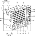
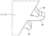
- a heat exchanger that performs heat exchange between a first fluid and a second fluid, A first duct plate; A second duct plate disposed opposite the first duct plate and forming a first flow path along which the first fluid flows together with the first duct plate; A plurality of flow path members having a second flow path, in which the first duct plate and the second duct plate are stacked in a direction facing each other in the first flow path, and the second fluid flows; A frame member provided at the opening of the first flow path formed by the first duct plate and the second duct plate; An insertion protrusion that protrudes from the first duct plate and the second duct plate toward the frame member and is inserted into an insertion hole provided in the frame member; A contact protrusion that protrudes from the first duct plate and the second duct plate toward the frame member and is fixed in contact with the frame member.
- the heat exchanger performs heat exchange between the first fluid and the second fluid, A first duct plate; A second duct plate disposed opposite the first duct plate and forming a first flow path along which the first fluid flows together with the first duct plate; A plurality of flow path members having a second flow path, in which the first duct plate and the second duct plate are stacked in a direction facing each other in the first flow path, and the second fluid flows; A frame member provided at the opening of the first flow path formed by the first duct plate and the second duct plate; A flange portion extending in a direction along the opening surface of the frame member from the first duct plate, and fixed in a state of contacting the frame member; An insertion protrusion that protrudes from the first duct plate and the second duct plate toward the frame member and is inserted into an insertion hole provided in the frame member; A contact protrusion that protrudes from the second duct plate toward the frame member and is fixed in a state of being in contact with the frame member.
- the insertion protrusion extending from the second duct plate is inserted into the insertion hole, the positional deviation between the second duct plate and the frame member in the direction parallel to the opening surface of the frame member is prevented. .
- the flange portion extending from the first duct plate and the frame member are in contact with each other, and the contact protrusion and the frame member extending from the second duct plate are in contact with each other, whereby the first duct plate and the second duct plate are configured. Variation in angle between the duct and the frame member is prevented. Therefore, this heat exchanger can improve the positioning accuracy between the duct and the frame member.
- this heat exchanger In this heat exchanger, the flange portion extends in a direction along the opening surface of the frame member. Therefore, this heat exchanger follows the change in dimensions even when the dimensions of the plurality of flow path members change in the stacking direction due to the melting of the brazing material provided in each component during brazing in the manufacturing process.
- the first duct plate and the frame member can be displaced in the stacking direction. Therefore, this heat exchanger can prevent occurrence of defective brazing of each component.
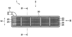
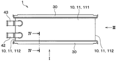
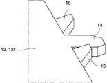
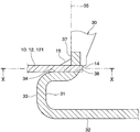
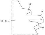
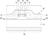
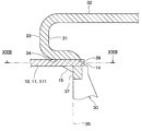
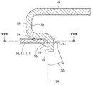
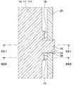
- FIG. 10 is a cross-sectional view taken along line XX in FIGS. 8 and 9. It is a fragmentary sectional view of the heat exchanger concerning a 2nd embodiment. It is a fragmentary sectional view of the heat exchanger concerning a 3rd embodiment. It is the elements on larger scale of the 2nd duct plate of the heat exchanger which concerns on 4th Embodiment, an insertion protrusion, and a contact protrusion. It is a fragmentary sectional view of the 2nd duct plate, a contact projection, and a caulking plate. It is a fragmentary sectional view of the heat exchanger concerning a 5th embodiment.
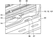
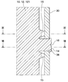
- the flange portion 36 extending from the first duct plate 11 along the opening surface 35 is fixed in a state of being in contact with the caulking plate 30.
- the insertion protrusion 14 protruding from the second duct plate 12 is inserted into the insertion hole 38 of the caulking plate 30, and the contact protrusion 15 is fixed in a state of being in contact with the stopper wall 37 of the caulking plate 30. .
- the contact protrusion 15 contacts the stopper wall 37 provided around the insertion hole 38 in the caulking plate 30.
- the contact protrusion 15 is provided on both sides of the insertion protrusion 14.
- the first duct plate 11, the second duct plate 12, the plurality of flow path members, the caulking plate 30, the flange portion 36, the insertion protrusion 14, the contact protrusion 15, and the like are brazed. It is fixed by.
- a second embodiment will be described.
- the second embodiment is obtained by changing a part of the connection method between the duct 10 and the caulking plate 30 with respect to the first embodiment, and is otherwise the same as the first embodiment, and therefore the first embodiment. Only different parts will be described.
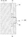
- connection portion 391 between the inner peripheral wall 34 and the stopper wall 37 is bent so as to be substantially perpendicular. Therefore, also in the fourth embodiment, the positioning accuracy between the second duct plate 12 and the caulking plate 30 is high. Therefore, 4th Embodiment can also have the same effect as 1st Embodiment.
- FIG. 10 A sixth embodiment will be described.
- the sixth embodiment is obtained by changing a part of the connection method between the duct 10 and the caulking plate 30 with respect to the first embodiment, and is otherwise the same as the first embodiment, and thus the first embodiment. Only different parts will be described.
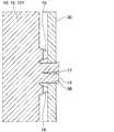
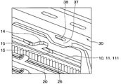
- the insertion protrusion 14 protruding from the first duct plate 11 and the second duct plate 12 is inserted into the insertion hole 38 of the caulking plate 30 and the contact protrusion 15 is caulked.
- the plate 30 is fixed in contact with the stopper wall 37 of the plate 30.
- the intercooler 1 can improve the positioning accuracy between the duct 10 and the caulking plate 30. That is, the sixth embodiment can achieve the same effects as the first embodiment.
- the insertion protrusion 14 has a polygonal shape, and the insertion hole 38 has a long hole shape.
- the shape of the insertion protrusion 14 and the insertion hole 38 is not limited.
- the insertion protrusion may be cylindrical or tapered, and the insertion hole 38 is polygonal, It may be circular or elliptical.
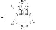
- the 1st viewpoint shown by one part or all part of the above-mentioned embodiment it is a heat exchanger which performs heat exchange with the 1st fluid and the 2nd fluid, Comprising: 1st duct plate, 2nd duct plate And a plurality of flow path members, frame members, flange portions, insertion protrusions, and contact protrusions.
- the first duct plate and the second duct plate are arranged to face each other and form a first flow path through which the first fluid flows.
- the plurality of flow path members have a second flow path through which the second fluid flows, and are stacked in a direction in which the first duct plate and the second duct plate face each other in the first flow path.
- the frame member is provided at the opening of the first flow path formed by the first duct plate and the second duct plate.
- the insertion protrusions protruding from the first duct plate and the second duct plate toward the frame member are inserted into insertion holes provided in the frame member.
- the contact protrusions that protrude from the first duct plate and the second duct plate to the frame member side are fixed in a state of being in contact with the frame member.
- the heat exchanger performs heat exchange between the first fluid and the second fluid, the first duct plate, the second duct plate, a plurality of flow path members, a frame member, a flange portion, An insertion protrusion and a contact protrusion are provided.
- the first duct plate and the second duct plate are arranged to face each other and form a first flow path through which the first fluid flows.
- the plurality of flow path members have a second flow path through which the second fluid flows, and are stacked in a direction in which the first duct plate and the second duct plate face each other in the first flow path.
- the frame member is provided at the opening of the first flow path formed by the first duct plate and the second duct plate.
- the insertion hole is a through-hole through which the insertion protrusion can pass.
- the insertion hole is a bag path-like hole formed halfway in the thickness direction of the frame member.
- the insertion protrusion is indexed in the state inserted in the insertion hole.
- the abutting protrusion abuts against a stopper wall provided around the insertion hole in the frame member.
- the contact protrusions are provided on both sides of the insertion protrusion.
- the first duct plate, the second duct plate, the plurality of flow path members, the frame member, the flange portion, the insertion protrusion, and the contact protrusion are fixed by brazing.
- the heat exchanger can improve the positioning accuracy between the duct and the frame member, and can prevent the fluid from leaking from the connection portion between the duct and the frame member.
Landscapes
- Engineering & Computer Science (AREA)
- Physics & Mathematics (AREA)
- Thermal Sciences (AREA)
- Mechanical Engineering (AREA)
- General Engineering & Computer Science (AREA)
- Heat-Exchange Devices With Radiators And Conduit Assemblies (AREA)
- Details Of Heat-Exchange And Heat-Transfer (AREA)
Priority Applications (2)
| Application Number | Priority Date | Filing Date | Title |
|---|---|---|---|
| DE112017007007.4T DE112017007007T5 (de) | 2017-02-07 | 2017-12-27 | Wärmetauscher |
| US16/524,522 US20190346211A1 (en) | 2017-02-07 | 2019-07-29 | Heat exchanger |
Applications Claiming Priority (2)
| Application Number | Priority Date | Filing Date | Title |
|---|---|---|---|
| JP2017020652A JP2018128183A (ja) | 2017-02-07 | 2017-02-07 | 熱交換器 |
| JP2017-020652 | 2017-09-21 |
Related Child Applications (1)
| Application Number | Title | Priority Date | Filing Date |
|---|---|---|---|
| US16/524,522 Continuation US20190346211A1 (en) | 2017-02-07 | 2019-07-29 | Heat exchanger |
Publications (1)
| Publication Number | Publication Date |
|---|---|
| WO2018146975A1 true WO2018146975A1 (ja) | 2018-08-16 |
Family
ID=63107479
Family Applications (1)
| Application Number | Title | Priority Date | Filing Date |
|---|---|---|---|
| PCT/JP2017/047109 Ceased WO2018146975A1 (ja) | 2017-02-07 | 2017-12-27 | 熱交換器 |
Country Status (4)
| Country | Link |
|---|---|
| US (1) | US20190346211A1 (enExample) |
| JP (1) | JP2018128183A (enExample) |
| DE (1) | DE112017007007T5 (enExample) |
| WO (1) | WO2018146975A1 (enExample) |
Families Citing this family (4)
| Publication number | Priority date | Publication date | Assignee | Title |
|---|---|---|---|---|
| JP6610777B2 (ja) * | 2016-04-20 | 2019-11-27 | 株式会社デンソー | 熱交換器およびその製造方法 |
| JP6848772B2 (ja) * | 2017-08-31 | 2021-03-24 | 株式会社デンソー | 熱交換器 |
| CN110186310A (zh) * | 2019-05-09 | 2019-08-30 | 浙江银轮机械股份有限公司 | 热交换器的主板、集管组件及其制造方法、热交换器 |
| JP7349821B2 (ja) * | 2019-06-10 | 2023-09-25 | 株式会社ティラド | 熱交換器 |
Citations (6)
| Publication number | Priority date | Publication date | Assignee | Title |
|---|---|---|---|---|
| JPH04340092A (ja) * | 1991-05-15 | 1992-11-26 | Nippondenso Co Ltd | 積層型熱交換器 |
| JPH06185889A (ja) * | 1992-12-14 | 1994-07-08 | Nippondenso Co Ltd | 熱交換器 |
| JP2007322003A (ja) * | 2006-05-30 | 2007-12-13 | Japan Climate Systems Corp | 熱交換器 |
| JP2013514513A (ja) * | 2009-12-18 | 2013-04-25 | ヴァレオ システム テルミク | 熱交換器 |
| JP2015185572A (ja) * | 2014-03-20 | 2015-10-22 | 住友電装株式会社 | 端子付プリント基板 |
| WO2016140203A1 (ja) * | 2015-03-02 | 2016-09-09 | 株式会社デンソー | 熱交換器 |
Family Cites Families (3)
| Publication number | Priority date | Publication date | Assignee | Title |
|---|---|---|---|---|
| JPS58158983U (ja) * | 1982-04-19 | 1983-10-22 | カルソニックカンセイ株式会社 | 熱交換器用タンクの導水パイプの構造 |
| JPH08621Y2 (ja) * | 1989-08-31 | 1996-01-10 | 昭和アルミニウム株式会社 | 熱交換器 |
| JP4239261B2 (ja) * | 1998-11-09 | 2009-03-18 | ダイキン工業株式会社 | 感温素子の取付構造 |
-
2017
- 2017-02-07 JP JP2017020652A patent/JP2018128183A/ja active Pending
- 2017-12-27 DE DE112017007007.4T patent/DE112017007007T5/de not_active Ceased
- 2017-12-27 WO PCT/JP2017/047109 patent/WO2018146975A1/ja not_active Ceased
-
2019
- 2019-07-29 US US16/524,522 patent/US20190346211A1/en not_active Abandoned
Patent Citations (6)
| Publication number | Priority date | Publication date | Assignee | Title |
|---|---|---|---|---|
| JPH04340092A (ja) * | 1991-05-15 | 1992-11-26 | Nippondenso Co Ltd | 積層型熱交換器 |
| JPH06185889A (ja) * | 1992-12-14 | 1994-07-08 | Nippondenso Co Ltd | 熱交換器 |
| JP2007322003A (ja) * | 2006-05-30 | 2007-12-13 | Japan Climate Systems Corp | 熱交換器 |
| JP2013514513A (ja) * | 2009-12-18 | 2013-04-25 | ヴァレオ システム テルミク | 熱交換器 |
| JP2015185572A (ja) * | 2014-03-20 | 2015-10-22 | 住友電装株式会社 | 端子付プリント基板 |
| WO2016140203A1 (ja) * | 2015-03-02 | 2016-09-09 | 株式会社デンソー | 熱交換器 |
Also Published As
| Publication number | Publication date |
|---|---|
| DE112017007007T5 (de) | 2019-10-31 |
| JP2018128183A (ja) | 2018-08-16 |
| US20190346211A1 (en) | 2019-11-14 |
Similar Documents
| Publication | Publication Date | Title |
|---|---|---|
| CN102138054B (zh) | 包括热交换器束和壳体的热交换器 | |
| US7204302B2 (en) | Exhaust gas heat exchanger | |
| US8002022B2 (en) | Heat exchanger, in particular exhaust gas heat exchanger for motor vehicles | |
| US8261815B2 (en) | Heat exchanger, in particular charge air cooler or exhaust gas cooler for an internal combustion engine of a motor vehicle and method for manufacturing it | |
| WO2018146975A1 (ja) | 熱交換器 | |
| US9970717B2 (en) | Heat exchanger | |
| US20160245597A1 (en) | Heat Exchanger for Cooling a Flow of Compressed Air Using a Liquid Coolant | |
| KR101897997B1 (ko) | 자동차 배기가스 냉각 열교환기 및 상기 열교환기를 제조하기 위한 방법 | |
| JP6619675B2 (ja) | 流路構造 | |
| US11143457B2 (en) | Heat exchanger | |
| WO2015037687A1 (ja) | ヘッダープレートレス熱交換器のタンク構造 | |
| JP2017083161A (ja) | 間接給気冷却器 | |
| WO2016140203A1 (ja) | 熱交換器 | |
| JP2008275246A (ja) | ヘッダプレートレス熱交換器 | |
| CN101595360B (zh) | 热交换器 | |
| WO2015093625A1 (ja) | ヘッダプレートレス型熱交換器 | |
| JP2007212084A (ja) | 熱交換器 | |
| JP6545920B2 (ja) | 熱交換器 | |
| US20160363380A1 (en) | Heat exchanger | |
| EP3755892B1 (en) | Modular intercooler block | |
| CN101523145B (zh) | 交替的板式无集管热交换器 | |
| JP6449808B2 (ja) | 熱交換器 | |
| JP2017161145A (ja) | 熱交換器 | |
| JP6992581B2 (ja) | 熱交換器 | |
| JP2019105403A (ja) | 熱交換器 |
Legal Events
| Date | Code | Title | Description |
|---|---|---|---|
| 121 | Ep: the epo has been informed by wipo that ep was designated in this application |
Ref document number: 17895729 Country of ref document: EP Kind code of ref document: A1 |
|
| 122 | Ep: pct application non-entry in european phase |
Ref document number: 17895729 Country of ref document: EP Kind code of ref document: A1 |