WO2018143151A1 - 測量用マーカ、及び測量システム - Google Patents
測量用マーカ、及び測量システム Download PDFInfo
- Publication number
- WO2018143151A1 WO2018143151A1 PCT/JP2018/002849 JP2018002849W WO2018143151A1 WO 2018143151 A1 WO2018143151 A1 WO 2018143151A1 JP 2018002849 W JP2018002849 W JP 2018002849W WO 2018143151 A1 WO2018143151 A1 WO 2018143151A1
- Authority
- WO
- WIPO (PCT)
- Prior art keywords
- surveying
- target
- marker
- display area
- code image
- Prior art date
- Legal status (The legal status is an assumption and is not a legal conclusion. Google has not performed a legal analysis and makes no representation as to the accuracy of the status listed.)
- Ceased
Links
Images

Classifications
-
- G—PHYSICS
- G01—MEASURING; TESTING
- G01C—MEASURING DISTANCES, LEVELS OR BEARINGS; SURVEYING; NAVIGATION; GYROSCOPIC INSTRUMENTS; PHOTOGRAMMETRY OR VIDEOGRAMMETRY
- G01C11/00—Photogrammetry or videogrammetry, e.g. stereogrammetry; Photographic surveying
- G01C11/04—Interpretation of pictures
-
- G—PHYSICS
- G01—MEASURING; TESTING
- G01C—MEASURING DISTANCES, LEVELS OR BEARINGS; SURVEYING; NAVIGATION; GYROSCOPIC INSTRUMENTS; PHOTOGRAMMETRY OR VIDEOGRAMMETRY
- G01C15/00—Surveying instruments or accessories not provided for in groups G01C1/00 - G01C13/00
- G01C15/02—Means for marking measuring points
- G01C15/06—Surveyors' staffs; Movable markers
Definitions
- the present invention relates to a surveying marker attached to a surveying object for surveying, and a surveying system provided with the surveying marker.
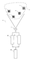
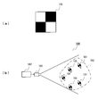
- FIG. 3 (a) is a plan view showing an example of a conventional example of a surveying marker
- FIG. 3 (b) is a block diagram showing an example of the configuration of a surveying system using the surveying marker.
- this surveying system a plurality of surveying markers 101 are attached to the surveying object 102, and the plurality of surveying markers 101 are photographed by the camera 103 and surveyed (for example, three of the targets displayed on each surveying marker 101). Measurement of dimensional position was performed.
- Patent No. 5051493 gazette
- the plurality of surveying markers 101 described above can not distinguish between the surveying markers due to the same pattern and the same shape, and in some cases, surveying can not be performed. For example, when photographing from two directions by two cameras, it is not possible to associate the plural survey markers 101 photographed by one camera with the plural survey markers 101 photographed by the other camera. , There was a risk of not being able to survey. Also, even in the case where a plurality of surveying markers 101 are continuously photographed by one camera, if the surveying markers 101 have been removed from the screen for some reason, the surveying images displayed before the removal. In some cases, it is difficult to associate the marker 101 with the surveying marker 101 that appears after the detachment, making it impossible to survey.
- An object of the present invention is to provide a surveying marker and a surveying system capable of solving the above-mentioned problems.
- the first aspect of the present invention is illustrated in FIG. 1, and in a surveying marker (1) attached to a surveying object (2) and surveyed by a photographing means (3) for surveying, A target display area (10) which is an area for displaying a survey target (10a); And a code image display area (11, 12, 13, 14) which is an area for displaying at least own ID information as a code image.
- a second aspect of the present invention is characterized in that the code image display area (11, 12, 13, 14) is disposed at a predetermined position based on the target display area (10).
- the target display area (10) is formed by a plurality of strip display areas (10b, 10c) arranged to intersect.
- the code image display area (11, 12, 13, 14) is characterized in that the code image display area (11, 12, 13, 14) is disposed at a position sandwiched by a pair of adjacent strip display areas (10b, 10c).
- the target display area (10) is formed by two strip display areas (10b, 10c) arranged in a substantially cross shape or a substantially X shape so as to cross each other.
- the code image display areas (11, 12, 13, 14) are characterized in that they are arranged at positions sandwiched by the band-like display areas (10b, 10c).
- a surveying marker (1) according to the present invention, the surveying marker (1) being disposed on at least one of the upper side, the lower side, the left side and the right side of the target display area (10). And an identification mark (4) for identifying the top, bottom, left, and right of the surveying marker (1) when the measurement marker (1) is attached.
- a sixth aspect of the present invention is characterized in that it has an auxiliary line (5a, 5b, 5c, 5d) indicated to indicate the center of itself and to sandwich the target display area (10).
- the target display area (10) displays the target (10a) by a color separation pattern and / or a gradation pattern.
- the code image display area (11, 12, 13, 14) is characterized in that at least its own ID information is displayed by a color separation pattern and / or a gradation pattern.
- the eighth aspect of the present invention is illustrated in FIG. 2 and is provided with the above-described surveying marker (1) attached to the surveying object (2); A photographing means (3) for photographing the target display area (10) displayed on the survey marker (1) and the code image display area (11, 12, 13, 14); Target position calculation means (60) for calculating the position of the target (10a) based on the image photographed by the photographing means (3); ID acquisition means (61) for acquiring the ID of the survey marker (1) based on the image captured by the imaging means (3); A target position storage means (62) for storing the position of the target (10a) calculated by the target position calculation means (60) as data associated with the ID acquired by the ID acquisition means (61) The system (6).
- each surveying marker since each surveying marker carries ID information, it can be distinguished from other surveying markers and surveying can not be performed due to confusion of surveying markers. It is possible to avoid such a situation and to carry out the survey correctly.
- the display position of the code image display area can be accurately identified, and the data carried by the code image display area can be read in a short time.
- the worker can attach the surveying marker to the survey target so that the top, bottom, left, and right are correct.
- an apparatus for surveying specifically, an apparatus for analyzing an image captured by the imaging means, an apparatus for obtaining an ID as described later, etc.
- the operator can easily know the horizontal and vertical of the surveying marker itself and the center of the marker, and the worker can properly state the surveying marker for the survey object ( In other words, it can be mounted at an appropriate position and posture.
- FIG. 1 is a plan view showing an example of the configuration of a surveying marker according to the present invention.
- FIG. 2 is a block diagram showing an example of the configuration of the surveying system according to the present invention.
- FIG. 3 (a) is a plan view showing an example of a conventional example of a surveying marker, and
- FIG. 3 (b) is a block diagram showing an example of the configuration of a surveying system using the surveying marker.
- the surveying marker according to the present invention as exemplified by reference numeral 1 in FIG.
- a target display area 10 which is an area for displaying a survey target 10a; -Code image display areas 11, 12, 13, 14 which are areas for displaying at least own ID information (that is, marker identification information capable of identifying the survey marker 1 from other survey markers 1) as a code image, Is equipped.
- the survey marker 1 is attached to any survey target 2 and used, and the target 10a is photographed by a photographing means (camera for photographing a moving image or a still image) 3 and the position of the target 10a (2 It is for specifying the position etc. of the survey object 2 by calculating the dimensional position and the three-dimensional position).
- the survey marker 1 is preferably in the form of a sheet (that is, in the form of a thin plate having flexibility), but of course the present invention is not limited to this, and the form other than the sheet is not excluded.
- a method of attaching the survey marker 1 to the survey object 2 sticking using an adhesive or the like is preferable, but other known methods other than sticking may be used.
- the display of the target 10a is performed in a light and shade pattern (that is, by arranging so that a plurality of corner portions of a dark portion such as black points one point)
- the target 10a is specified at one point
- ⁇ Even if it is done by the color pattern, ⁇ Even if it is done by both light and dark patterns and color separation patterns, or -It may be made to carry out according to the difference in the quality of the material (for example, the arrangement state of the member with high reflectance and the member with low reflectance).
- the display of the code image is performed by a light and shade pattern (that is, a pattern formed by a dark portion and a light portion such as a barcode or QR code (registered trademark)).
- a light and shade pattern that is, a pattern formed by a dark portion and a light portion such as a barcode or QR code (registered trademark)
- ⁇ Even if it is done by the color pattern ⁇ Even if it is done by both light and dark patterns and color separation patterns, or -It may be made to carry out according to the difference in the quality of the material (for example, the arrangement state of the member with high reflectance and the member with low reflectance).
- the code image carries not only the ID information of the survey marker itself but also other information (for example, information on the shape, size, etc. of the survey object 2 to which the survey marker is attached). Also good.
- the code image display areas 11, 12, 13, 14 themselves and the pattern inside them are rectangular (that is, rectangular or square), but of course are limited thereto Alternatively, the shape
- each surveying marker 1 since each surveying marker 1 carries ID information, it can be distinguished from other surveying markers 1 and a situation where surveying can not be performed due to confusion of surveying markers is avoided. And can do surveying accurately.
- the code image display areas 11, 12, 13 and 14 described above may be arranged at predetermined positions based on the target display area 10. That is, the code image display area may be disposed at any position as long as it is a position based on the target display area and can be clearly recognized by using the target display area as a reference. In such a case, the display position of the code image display area can be accurately identified by using the target display area as a reference, and data carried by the code image display area can be read in a short time.
- the target display area 10 is formed of a plurality of strip display areas 10 b and 10 c arranged to intersect with each other, and the code image display areas 11, 12, 13, 14 may be disposed at a position sandwiched between the pair of strip-shaped display areas 10b and 10c adjacent to each other.
- the code image display areas 11, 12, 13 and 14 are formed in a substantially cross shape by two strip display areas 10b and 10c arranged to intersect with each other.
- the present invention is not limited to this, and may be formed in a substantially X shape, or may be formed in another shape (that is, a shape in which three or more strip display regions intersect).
- the code image display areas 11, 12, 13, 14 are respectively formed in all of the positions sandwiched by the strip display areas 10b, 10c (that is, four parts).
- the present invention is not limited to this, as long as it is formed in at least one portion.
- a worker who attaches the survey marker 1 to the survey object 2 can clearly distinguish it from the target display area 10 and the code image display areas 11, 12, 13, 14 (hereinafter referred to as “identification mark It is preferable to arrange “4” at least one of the upper side, the lower side, the left side and the right side of the target display area 10. When such an identification mark 4 is provided, the worker can attach the surveying marker 1 to the survey object 2 so that the top, bottom, left, and right are correct.
- an apparatus for surveying (specifically, an apparatus for analyzing an image photographed by the photographing means 3 and an apparatus such as an ID acquiring means 61 described later) is the code image display area 11, 12, 13,
- the display position of 14 can be specified accurately at high speed, and the data carried by the code image display areas 11, 12, 13, 14 can be read at high speed.
- the identification mark 4 can be identified by the operator due to the difference in color density, but of course the present invention is not limited to this, and the color or the shape of the mark itself etc. You may make it distinguishable.
- auxiliary lines horizontal lines or vertical lines
- 5a, 5b, 5c, 5d which point to the center of the surveying marker itself (preferably, the position of the target 10a described above) and are displayed sandwiching the target display area 10. It is good to have In such a case, the operator can easily know the horizontal and vertical of the surveying marker itself and the center of the marker, and the worker can use the surveying marker 1 appropriately for the surveying object 2 ( In other words, it can be mounted at an appropriate position and posture.
- the surveying system is illustrated in FIG. -The above-mentioned survey marker 1 attached to the survey target 2, An imaging means 3 for imaging the target display area 10 displayed on the survey marker 1 and the code image display areas 11, 12, 13, 14; Target position calculation means 60 for calculating the position of the target 10a based on the image taken by the imaging means 3; An ID acquisition unit 61 that acquires an ID of the survey marker 1 based on an image captured by the imaging unit 3; Target position storage means 62 for storing the position of the target 10a calculated by the target position calculation means 60 as data associated with the ID acquired by the ID acquisition means 61, Is equipped.
- each surveying marker 1 since each surveying marker 1 carries ID information, it can be distinguished from other surveying markers 1 and a situation where surveying can not be performed due to confusion of surveying markers is avoided. And can do surveying accurately.
- the surveying marker and surveying system according to the present invention can be applied to applications such as SLAM (Simultaneous Localization and Mapping), triangulation, and photogrammetry.
- SLAM Simultaneous Localization and Mapping
- triangulation triangulation
- photogrammetry photogrammetry
Landscapes
- Engineering & Computer Science (AREA)
- Physics & Mathematics (AREA)
- General Physics & Mathematics (AREA)
- Radar, Positioning & Navigation (AREA)
- Remote Sensing (AREA)
- Multimedia (AREA)
- Measurement Of Optical Distance (AREA)
- Length Measuring Devices By Optical Means (AREA)
Abstract
【課題】測量用マーカの混同により測量ができないというような事態を回避し、測量を正確に行うことができるようにする。 【解決手段】本発明に係る測量用マーカ1は、測量用のターゲット10aを表示する領域であるターゲット表示領域10と、自身のID情報(つまり、その測量用マーカ1を他の測量用マーカ1から識別できるマーカ識別情報)をコード画像として表示する領域であるコード画像表示領域11,12,13,14と、を備えている。したがって、測量用マーカの混同により測量ができないというような事態を回避し、測量を正確に行うことができる。
Description
本発明は、測量するために測量対象物に取り付けられる測量用マーカ、及び該測量用マーカを備えた測量システムに関する。
従来、測量するために測量対象物に取り付けられる測量用マーカや、該測量用マーカを使った測量システムについては種々の構成のものが提案されている(例えば、特許文献1参照)。
図3(a)は、測量用マーカの従来例の一例を示す平面図であり、同図(b)は、該測量用マーカを使用した測量システムの構成の一例を示すブロック図である。この測量システムにおいては、測量対象物102に複数の測量用マーカ101を取り付け、該複数の測量用マーカ101をカメラ103で撮影して測量(例えば、各測量用マーカ101に表示されるターゲットの3次元位置の測定)を行っていた。
しかしながら、上述した複数の測量用マーカ101は同じ模様で同じ形状のために測量用マーカどうしを区別することができず、測量ができない場合があった。例えば、2台のカメラで二方向から撮影するような場合は、一方のカメラで撮影した複数の測量用マーカ101と他方のカメラで撮影した複数の測量用マーカ101とを対応させることができず、測量ができないおそれがあった。また、1台のカメラで複数の測量用マーカ101を連続撮影するような場合でも、該測量用マーカ101が何らかの理由で画面から外れてしまった場合には、該外れる前に映っていた測量用マーカ101と該外れた後に映っている測量用マーカ101とを対応付けることが困難となり測量ができない場合があった。
本発明は、上述の問題を解消することのできる測量用マーカ及び測量システムを提供することを目的とするものである。
本発明の第1の観点は、図1に例示するものであって、測量するために測量対象物(2)に取り付けられて撮影手段(3)で撮影される測量用マーカ(1)において、
測量用のターゲット(10a)を表示する領域であるターゲット表示領域(10)と、
少なくとも自身のID情報をコード画像として表示する領域であるコード画像表示領域(11,12,13,14)と、を備えたことを特徴とする。
測量用のターゲット(10a)を表示する領域であるターゲット表示領域(10)と、
少なくとも自身のID情報をコード画像として表示する領域であるコード画像表示領域(11,12,13,14)と、を備えたことを特徴とする。
本発明の第2の観点は、前記コード画像表示領域(11,12,13,14)が、前記ターゲット表示領域(10)を基準とした所定の位置に配置されていることを特徴とする。
本発明の第3の観点は、前記ターゲット表示領域(10)が、交差するように配置された複数の帯状表示領域(10b,10c)により形成され、
前記コード画像表示領域(11,12,13,14)は、互いに隣接する一対の前記帯状表示領域(10b,10c)に挟まれる位置に配置されてなることを特徴とする。
前記コード画像表示領域(11,12,13,14)は、互いに隣接する一対の前記帯状表示領域(10b,10c)に挟まれる位置に配置されてなることを特徴とする。
本発明の第4の観点は、前記ターゲット表示領域(10)が、交差するように略十字状又は略X字状に配置された2つの帯状表示領域(10b,10c)により形成され、
前記コード画像表示領域(11,12,13,14)は、それらの帯状表示領域(10b,10c)に挟まれる位置にそれぞれ配置されてなることを特徴とする。
前記コード画像表示領域(11,12,13,14)は、それらの帯状表示領域(10b,10c)に挟まれる位置にそれぞれ配置されてなることを特徴とする。
本発明の第5の観点は、前記ターゲット表示領域(10)の上方、下方、左方及び右方のうちの少なくとも一方に配置されて前記測量用マーカ(1)を前記測量対象物(2)に取り付ける際に該測量用マーカ(1)の上下左右を識別できるようにする識別用マーク(4)、を備えたことを特徴とする。
本発明の第6の観点は、自身の中心を指し示すと共に前記ターゲット表示領域(10)を挟むように表示された補助線(5a,5b,5c,5d)、を備えたことを特徴とする。
本発明の第7の観点は、前記ターゲット表示領域(10)が、色分け模様及び/又は濃淡模様により前記ターゲット(10a)を表示し、
前記コード画像表示領域(11,12,13,14)は、色分け模様及び/又は濃淡模様により少なくとも自身のID情報を表示する、ことを特徴とする。
前記コード画像表示領域(11,12,13,14)は、色分け模様及び/又は濃淡模様により少なくとも自身のID情報を表示する、ことを特徴とする。
本発明の第8の観点は、図2に例示するものであって、測量対象物(2)に取り付けられてなる上述した測量用マーカ(1)と、
該測量用マーカ(1)に表示されてなる前記ターゲット表示領域(10)と前記コード画像表示領域(11,12,13,14)とを撮影する撮影手段(3)と、
該撮影手段(3)が撮影した画像に基づいて前記ターゲット(10a)の位置を算出するターゲット位置算出手段(60)と、
前記撮影手段(3)が撮影した画像に基づいて前記測量用マーカ(1)のIDを取得するID取得手段(61)と、
該ターゲット位置算出手段(60)が算出した前記ターゲット(10a)の位置を前記ID取得手段(61)が取得したIDに関連付けたデータとして保存するターゲット位置保存手段(62)と、を備えた測量システム(6)に関する。
該測量用マーカ(1)に表示されてなる前記ターゲット表示領域(10)と前記コード画像表示領域(11,12,13,14)とを撮影する撮影手段(3)と、
該撮影手段(3)が撮影した画像に基づいて前記ターゲット(10a)の位置を算出するターゲット位置算出手段(60)と、
前記撮影手段(3)が撮影した画像に基づいて前記測量用マーカ(1)のIDを取得するID取得手段(61)と、
該ターゲット位置算出手段(60)が算出した前記ターゲット(10a)の位置を前記ID取得手段(61)が取得したIDに関連付けたデータとして保存するターゲット位置保存手段(62)と、を備えた測量システム(6)に関する。
なお、括弧内の番号などは、図面における対応する要素を示す便宜的なものであり、従って、本記述は図面上の記載に限定拘束されるものではない。
上記した第1、7及び8の観点によれば、各測量用マーカはID情報を担持しているため、他の測量用マーカと区別することができ、測量用マーカの混同により測量ができないというような事態を回避することができ、測量を正確に行うことができる。
上記した第2乃至4の観点によれば、前記コード画像表示領域の表示位置を正確に特定でき、該コード画像表示領域が担持するデータを短時間で読み取ることができる。
上記した第5の観点によれば、作業者は、上下左右が正しくなるように前記測量用マーカを前記測量対象物に取り付けることができる。その結果、測量のための装置(具体的には、前記撮影手段が撮影した画像を解析する装置や、後述するID取得手段などの装置)は前記コード画像表示領域の表示位置を高速で正確に特定でき、該コード画像表示領域が担持するデータを高速で読み取ることができる。
上記した第6の観点によれば、前記測量用マーカ自身の水平や垂直やマーカの中心を作業者が容易に知ることができ、作業者は該測量用マーカを測量対象物に適切な状態(つまり、適切な位置や姿勢)に取り付けることができる。
以下、図1及び図2に沿って、本発明の実施の形態について説明する。
本発明に係る測量用マーカは、図1に符号1で例示するように、
・ 測量用のターゲット10aを表示する領域であるターゲット表示領域10と、
・ 少なくとも自身のID情報(つまり、その測量用マーカ1を他の測量用マーカ1から識別できるマーカ識別情報)をコード画像として表示する領域であるコード画像表示領域11,12,13,14と、
を備えている。この測量用マーカ1は、何らかの測量対象物2に取り付けて使用するものであって、前記ターゲット10aを撮影手段(動画や静止画を撮影するカメラ)3で撮影して該ターゲット10aの位置(2次元位置や3次元位置)を算出することによって該測量対象物2の位置などを特定するためのものである。
・ 測量用のターゲット10aを表示する領域であるターゲット表示領域10と、
・ 少なくとも自身のID情報(つまり、その測量用マーカ1を他の測量用マーカ1から識別できるマーカ識別情報)をコード画像として表示する領域であるコード画像表示領域11,12,13,14と、
を備えている。この測量用マーカ1は、何らかの測量対象物2に取り付けて使用するものであって、前記ターゲット10aを撮影手段(動画や静止画を撮影するカメラ)3で撮影して該ターゲット10aの位置(2次元位置や3次元位置)を算出することによって該測量対象物2の位置などを特定するためのものである。
この測量用マーカ1はシート状(つまり、可撓性を有する薄板状)であることが好ましいが、もちろんこれに限られるものではなく、シート状以外の形状を排除するものではない。また、この測量用マーカ1を前記測量対象物2に取り付ける方法としては、接着剤などを用いた貼着が好ましいが、貼着以外の他の公知の方法を用いても良い。
なお、図1に示す例では、前記ターゲット10aの表示は濃淡模様により行っているが(つまり、黒などの色の濃い部分の複数の角部が一点を指し示すように配置されることにより、その一点でターゲット10aを特定しているが)、もちろんこれに限られるものではなく、
・ 色分け模様によって行うようにしても、
・ 濃淡模様と色分け模様の両方によって行うようにしても、或いは、
・ 材質の違い(例えば、反射率の高い部材と反射率の低い部材との配置状態)によって行うようにしても良い。
・ 色分け模様によって行うようにしても、
・ 濃淡模様と色分け模様の両方によって行うようにしても、或いは、
・ 材質の違い(例えば、反射率の高い部材と反射率の低い部材との配置状態)によって行うようにしても良い。
また、図1に示す例では、前記コード画像の表示は濃淡模様(つまり、バーコードやQRコード(登録商標)のように色の濃い部分と色の薄い部分とによって形成された模様)により行っているが、もちろんこれに限られるものではなく、
・ 色分け模様によって行うようにしても、
・ 濃淡模様と色分け模様の両方によって行うようにしても、或いは、
・ 材質の違い(例えば、反射率の高い部材と反射率の低い部材との配置状態)によって行うようにしても良い。また、前記コード画像は、測量用マーカ自身のID情報だけでなく、その他の情報(例えば、該測量用マーカが取り付けられる測量対象物2の形状や寸法等についての情報)を担持するようにしても良い。さらに、図1に示す例では、コード画像表示領域11,12,13,14自体やその内部の模様は矩形状(つまり、長方形状や正方形状)をしているが、もちろんこれに限られるものではなく、矩形以外の形状(例えば、円形)をしていても良い。
・ 色分け模様によって行うようにしても、
・ 濃淡模様と色分け模様の両方によって行うようにしても、或いは、
・ 材質の違い(例えば、反射率の高い部材と反射率の低い部材との配置状態)によって行うようにしても良い。また、前記コード画像は、測量用マーカ自身のID情報だけでなく、その他の情報(例えば、該測量用マーカが取り付けられる測量対象物2の形状や寸法等についての情報)を担持するようにしても良い。さらに、図1に示す例では、コード画像表示領域11,12,13,14自体やその内部の模様は矩形状(つまり、長方形状や正方形状)をしているが、もちろんこれに限られるものではなく、矩形以外の形状(例えば、円形)をしていても良い。
本発明によれば、各測量用マーカ1はID情報を担持しているため、他の測量用マーカ1と区別することができ、測量用マーカの混同により測量ができないというような事態を回避することができ、測量を正確に行うことができる。
ところで、上述したコード画像表示領域11,12,13,14は、前記ターゲット表示領域10を基準とした所定の位置に配置しておくと良い。つまり、該コード画像表示領域は、前記ターゲット表示領域を基準とした位置であって該ターゲット表示領域を基準とすることによって明確に認識できる位置であればどこの位置に配置しても良い。そのようにした場合には、前記ターゲット表示領域を基準とすることによって前記コード画像表示領域の表示位置を正確に特定でき、該コード画像表示領域が担持するデータを短時間で読み取ることができる。ここで、図1に例示するように、前記ターゲット表示領域10を、交差するように配置された複数の帯状表示領域10b,10cにより形成しておき、前記コード画像表示領域11,12,13,14は、互いに隣接する一対の前記帯状表示領域10b,10cに挟まれる位置に配置しておいても良い。なお、図1に示す例では、前記コード画像表示領域11,12,13,14は、交差するように配置された2つの帯状表示領域10b,10cによって略十字状に形成されているが、もちろんこれに限られるものではなく、略X字状に形成されても、或いはその他の形状(つまり、3つ以上の帯状表示領域が交差するような形状)に形成されていても良い。また、図1に示す例では、前記コード画像表示領域11,12,13,14は、前記帯状表示領域10b,10cに挟まれる位置の全て(つまり、4つの部分)にそれぞれ形成されているが、もちろんこれに限られるものではなく、少なくとも1つの部分に形成されていれば良い。
一方、前記測量用マーカ1を前記測量対象物2に取り付ける作業者が、前記ターゲット表示領域10や前記コード画像表示領域11,12,13,14と明確に区別できるマーク(以下、“識別用マーク”とする)4を、前記ターゲット表示領域10の上方、下方、左方及び右方のうちの少なくとも一方に配置しておくと良い。そのような識別用マーク4を設けた場合には、その作業者は、上下左右が正しくなるように前記測量用マーカ1を前記測量対象物2に取り付けることができる。その結果、測量のための装置(具体的には、前記撮影手段3が撮影した画像を解析する装置や、後述するID取得手段61などの装置)は前記コード画像表示領域11,12,13,14の表示位置を高速で正確に特定でき、該コード画像表示領域11,12,13,14が担持するデータを高速で読み取ることができる。なお、図1に示す例では、前記識別用マーク4は色の濃淡の違いによって作業者が識別できるようになっているが、もちろんこれに限られるものではなく、色彩やマーク自体の形状等によって識別できるようにしても良い。
一方、前記測量用マーカ自身の中心(好ましくは、上述したターゲット10aの位置)を指し示すと共に前記ターゲット表示領域10を挟むように表示された補助線(水平線や垂直線)5a,5b,5c,5dを設けておくと良い。そのようにした場合には、前記測量用マーカ自身の水平や垂直やマーカの中心を作業者が容易に知ることができ、作業者は該測量用マーカ1を測量対象物2に適切な状態(つまり、適切な位置や姿勢)に取り付けることができる。
本発明に係る測量システムは、図2に符号6で例示するものであって、
・ 測量対象物2に取り付けられてなる上述した測量用マーカ1と、
・ 該測量用マーカ1に表示されてなる前記ターゲット表示領域10と前記コード画像表示領域11,12,13,14とを撮影する撮影手段3と、
・ 該撮影手段3が撮影した画像に基づいて前記ターゲット10aの位置を算出するターゲット位置算出手段60と、
・ 前記撮影手段3が撮影した画像に基づいて前記測量用マーカ1のIDを取得するID取得手段61と、
・ 該ターゲット位置算出手段60が算出した前記ターゲット10aの位置を前記ID取得手段61が取得したIDに関連付けたデータとして保存するターゲット位置保存手段62と、
を備えている。
・ 測量対象物2に取り付けられてなる上述した測量用マーカ1と、
・ 該測量用マーカ1に表示されてなる前記ターゲット表示領域10と前記コード画像表示領域11,12,13,14とを撮影する撮影手段3と、
・ 該撮影手段3が撮影した画像に基づいて前記ターゲット10aの位置を算出するターゲット位置算出手段60と、
・ 前記撮影手段3が撮影した画像に基づいて前記測量用マーカ1のIDを取得するID取得手段61と、
・ 該ターゲット位置算出手段60が算出した前記ターゲット10aの位置を前記ID取得手段61が取得したIDに関連付けたデータとして保存するターゲット位置保存手段62と、
を備えている。
本発明によれば、各測量用マーカ1はID情報を担持しているため、他の測量用マーカ1と区別することができ、測量用マーカの混同により測量ができないというような事態を回避することができ、測量を正確に行うことができる。
本発明に係る測量用マーカや測量システムは、SLAM(Simultaneous Localization and Mapping)や三角測量や写真測量などの用途に適用できる。
1 測量用マーカ
2 測量対象物
3 撮影手段
4 識別用マーク
5a,5b,5c,5d 補助線
6 測量システム
10 ターゲット表示領域
10a ターゲット
10b,10c 帯状表示領域
11,12,13,14 コード画像表示領域
60 ターゲット位置算出手段
61 ID取得手段
62 ターゲット位置保存手段
2 測量対象物
3 撮影手段
4 識別用マーク
5a,5b,5c,5d 補助線
6 測量システム
10 ターゲット表示領域
10a ターゲット
10b,10c 帯状表示領域
11,12,13,14 コード画像表示領域
60 ターゲット位置算出手段
61 ID取得手段
62 ターゲット位置保存手段
Claims (8)
- 測量するために測量対象物に取り付けられて撮影手段で撮影される測量用マーカにおいて、
測量用のターゲットを表示する領域であるターゲット表示領域と、
少なくとも自身のID情報をコード画像として表示する領域であるコード画像表示領域と、
を備えたことを特徴とする測量用マーカ。 - 前記コード画像表示領域は、前記ターゲット表示領域を基準とした所定の位置に配置されている、
ことを特徴とする請求項1に記載の測量用マーカ。 - 前記ターゲット表示領域は、交差するように配置された複数の帯状表示領域により形成され、
前記コード画像表示領域は、互いに隣接する一対の前記帯状表示領域に挟まれる位置に配置されてなる、
ことを特徴とする請求項2に記載の測量用マーカ。 - 前記ターゲット表示領域は、交差するように略十字状又は略X字状に配置された2つの帯状表示領域により形成され、
前記コード画像表示領域は、それらの帯状表示領域に挟まれる位置にそれぞれ配置されてなる、
ことを特徴とする請求項3に記載の測量用マーカ。 - 前記ターゲット表示領域の上方、下方、左方及び右方のうちの少なくとも一方に配置されて前記測量用マーカを前記測量対象物に取り付ける際に該測量用マーカの上下左右を識別できるようにする識別用マーク、
を備えたことを特徴とする請求項1乃至4のいずれか1項に記載の測量用マーカ。 - 自身の中心を指し示すと共に前記ターゲット表示領域を挟むように表示された補助線、
を備えたことを特徴とする請求項1乃至5のいずれか1項に記載の測量用マーカ。 - 前記ターゲット表示領域は、色分け模様及び/又は濃淡模様により前記ターゲットを表示し、
前記コード画像表示領域は、色分け模様及び/又は濃淡模様により少なくとも自身のID情報を表示する、
ことを特徴とする請求項1乃至6のいずれか1項に記載の測量用マーカ。 - 測量対象物に取り付けられてなる請求項1乃至7のいずれか1項に記載の測量用マーカと、
該測量用マーカに表示されてなる前記ターゲット表示領域と前記コード画像表示領域とを撮影する撮影手段と、
該撮影手段が撮影した画像に基づいて前記ターゲットの位置を算出するターゲット位置算出手段と、
前記撮影手段が撮影した画像に基づいて前記測量用マーカのIDを取得するID取得手段と、
該ターゲット位置算出手段が算出した前記ターゲットの位置を前記ID取得手段が取得したIDに関連付けたデータとして保存するターゲット位置保存手段と、
を備えたことを特徴とする測量システム。
Priority Applications (1)
| Application Number | Priority Date | Filing Date | Title |
|---|---|---|---|
| JP2018565539A JP6672487B2 (ja) | 2017-01-31 | 2018-01-30 | 測量用マーカ、及び測量システム |
Applications Claiming Priority (2)
| Application Number | Priority Date | Filing Date | Title |
|---|---|---|---|
| JP2017-015104 | 2017-01-31 | ||
| JP2017015104 | 2017-01-31 |
Publications (1)
| Publication Number | Publication Date |
|---|---|
| WO2018143151A1 true WO2018143151A1 (ja) | 2018-08-09 |
Family
ID=63040746
Family Applications (1)
| Application Number | Title | Priority Date | Filing Date |
|---|---|---|---|
| PCT/JP2018/002849 Ceased WO2018143151A1 (ja) | 2017-01-31 | 2018-01-30 | 測量用マーカ、及び測量システム |
Country Status (2)
| Country | Link |
|---|---|
| JP (1) | JP6672487B2 (ja) |
| WO (1) | WO2018143151A1 (ja) |
Cited By (2)
| Publication number | Priority date | Publication date | Assignee | Title |
|---|---|---|---|---|
| WO2023282203A1 (ja) * | 2021-07-08 | 2023-01-12 | 株式会社小松製作所 | 作業機械の制御システム、作業機械、及び作業機械の制御方法 |
| WO2023162564A1 (ja) * | 2022-02-28 | 2023-08-31 | 株式会社イクシス | 測量方法、ターゲットマーカ、及び測量システム |
Citations (5)
| Publication number | Priority date | Publication date | Assignee | Title |
|---|---|---|---|---|
| JPH09218021A (ja) * | 1996-02-14 | 1997-08-19 | Topy Ind Ltd | カラー識別ターゲット |
| JP2003214851A (ja) * | 2002-01-22 | 2003-07-30 | Leica Geosystems Ag | ターゲットマークを自動検索する方法、ターゲットマークを自動検索する装置、受信ユニット、測地計および測地システム |
| JP2014102246A (ja) * | 2012-10-24 | 2014-06-05 | National Institute Of Advanced Industrial & Technology | 位置姿勢検出システム |
| CN104778488A (zh) * | 2014-11-28 | 2015-07-15 | 华北水利水电大学 | 基于bim的钢结构建筑定位贴片 |
| JP2016121450A (ja) * | 2014-12-24 | 2016-07-07 | 日本車輌製造株式会社 | 計測用治具 |
Family Cites Families (3)
| Publication number | Priority date | Publication date | Assignee | Title |
|---|---|---|---|---|
| JPH10206159A (ja) * | 1997-01-17 | 1998-08-07 | Nikon Corp | 測量機用ターゲット |
| JP2003269960A (ja) * | 2002-03-18 | 2003-09-25 | Pentax Precision Co Ltd | 測量機用光学照準器 |
| EP2405236B1 (de) * | 2010-07-07 | 2012-10-31 | Leica Geosystems AG | Geodätisches Vermessungsgerät mit automatischer hochpräziser Zielpunkt-Anzielfunktionalität |
-
2018
- 2018-01-30 JP JP2018565539A patent/JP6672487B2/ja active Active
- 2018-01-30 WO PCT/JP2018/002849 patent/WO2018143151A1/ja not_active Ceased
Patent Citations (5)
| Publication number | Priority date | Publication date | Assignee | Title |
|---|---|---|---|---|
| JPH09218021A (ja) * | 1996-02-14 | 1997-08-19 | Topy Ind Ltd | カラー識別ターゲット |
| JP2003214851A (ja) * | 2002-01-22 | 2003-07-30 | Leica Geosystems Ag | ターゲットマークを自動検索する方法、ターゲットマークを自動検索する装置、受信ユニット、測地計および測地システム |
| JP2014102246A (ja) * | 2012-10-24 | 2014-06-05 | National Institute Of Advanced Industrial & Technology | 位置姿勢検出システム |
| CN104778488A (zh) * | 2014-11-28 | 2015-07-15 | 华北水利水电大学 | 基于bim的钢结构建筑定位贴片 |
| JP2016121450A (ja) * | 2014-12-24 | 2016-07-07 | 日本車輌製造株式会社 | 計測用治具 |
Cited By (3)
| Publication number | Priority date | Publication date | Assignee | Title |
|---|---|---|---|---|
| WO2023282203A1 (ja) * | 2021-07-08 | 2023-01-12 | 株式会社小松製作所 | 作業機械の制御システム、作業機械、及び作業機械の制御方法 |
| CN117396653A (zh) * | 2021-07-08 | 2024-01-12 | 株式会社小松制作所 | 作业机械的控制系统、作业机械、以及作业机械的控制方法 |
| WO2023162564A1 (ja) * | 2022-02-28 | 2023-08-31 | 株式会社イクシス | 測量方法、ターゲットマーカ、及び測量システム |
Also Published As
| Publication number | Publication date |
|---|---|
| JPWO2018143151A1 (ja) | 2019-12-19 |
| JP6672487B2 (ja) | 2020-03-25 |
Similar Documents
| Publication | Publication Date | Title |
|---|---|---|
| US9182220B2 (en) | Image photographing device and method for three-dimensional measurement | |
| JP5207719B2 (ja) | カラーコード付き標識、カラーコード抽出手段及び三次元計測システム | |
| US8591401B2 (en) | Endoscope apparatus displaying information indicating gravity direction on screen | |
| US20120162360A1 (en) | Wide-Angle Image Pickup Unit And Measuring Device | |
| EP2476997B1 (en) | Electronic level device and level staff associated thereto | |
| JP2010219825A (ja) | 三次元計測用画像撮影装置 | |
| JP2018507407A5 (ja) | ||
| JP2011179980A (ja) | 立体マーカを利用した位置計測システム | |
| US12137984B2 (en) | Technique of determining a pose of a surgical registration device | |
| CN103649775A (zh) | 用于评估识别标记的系统、识别标记及其用途 | |
| US9008361B2 (en) | Method for visualizing zones of higher activity in surveillance scenes | |
| JP4909543B2 (ja) | 三次元計測システム及びその方法 | |
| JP2018124843A (ja) | 現場施工管理システム | |
| JP5002144B2 (ja) | 三次元計測用投影装置及びシステム | |
| US11430153B2 (en) | Method for detecting an arrangement of at least two cameras of a multi-camera system of a mobile carrier platform relative to one another and method for detecting an arrangement of the camera with respect to an object outside the mobile carrier platform | |
| AU2014310841A1 (en) | Optical tracking | |
| CN112415010A (zh) | 一种成像检测方法及系统 | |
| JP2003042732A (ja) | 表面形状測定装置及びその方法、表面形状測定プログラム、並びに表面状態図化装置 | |
| WO2018143151A1 (ja) | 測量用マーカ、及び測量システム | |
| KR102227031B1 (ko) | 화상데이터 내의 척도마커의 추적을 통한 구조물 표면의 균열 감시 방법 | |
| JP2009140402A (ja) | 情報表示装置、情報表示方法、情報表示プログラム及び情報表示プログラムを記録した記録媒体 | |
| JP2018055246A (ja) | 画像処理装置、画像処理方法および画像処理用プログラム | |
| KR101766470B1 (ko) | 기기 판독 가능한 폼 구조 및 시스템 및 적어도 하나의 사용자 표시를 해석하는 방법 | |
| JP2015059812A (ja) | 現場見取図作成システムおよびレーザ計測装置 | |
| US10859377B2 (en) | Method for improving position information associated with a collection of images |
Legal Events
| Date | Code | Title | Description |
|---|---|---|---|
| 121 | Ep: the epo has been informed by wipo that ep was designated in this application |
Ref document number: 18747605 Country of ref document: EP Kind code of ref document: A1 |
|
| ENP | Entry into the national phase |
Ref document number: 2018565539 Country of ref document: JP Kind code of ref document: A |
|
| NENP | Non-entry into the national phase |
Ref country code: DE |
|
| 122 | Ep: pct application non-entry in european phase |
Ref document number: 18747605 Country of ref document: EP Kind code of ref document: A1 |