WO2018143138A1 - Rolling bearing - Google Patents
Rolling bearing Download PDFInfo
- Publication number
- WO2018143138A1 WO2018143138A1 PCT/JP2018/002808 JP2018002808W WO2018143138A1 WO 2018143138 A1 WO2018143138 A1 WO 2018143138A1 JP 2018002808 W JP2018002808 W JP 2018002808W WO 2018143138 A1 WO2018143138 A1 WO 2018143138A1
- Authority
- WO
- WIPO (PCT)
- Prior art keywords
- coating
- film
- bearing
- test
- layer
- Prior art date
Links
Images


Classifications
-
- F—MECHANICAL ENGINEERING; LIGHTING; HEATING; WEAPONS; BLASTING
- F16—ENGINEERING ELEMENTS AND UNITS; GENERAL MEASURES FOR PRODUCING AND MAINTAINING EFFECTIVE FUNCTIONING OF MACHINES OR INSTALLATIONS; THERMAL INSULATION IN GENERAL
- F16C—SHAFTS; FLEXIBLE SHAFTS; ELEMENTS OR CRANKSHAFT MECHANISMS; ROTARY BODIES OTHER THAN GEARING ELEMENTS; BEARINGS
- F16C33/00—Parts of bearings; Special methods for making bearings or parts thereof
- F16C33/30—Parts of ball or roller bearings
- F16C33/58—Raceways; Race rings
- F16C33/62—Selection of substances
-
- F—MECHANICAL ENGINEERING; LIGHTING; HEATING; WEAPONS; BLASTING
- F16—ENGINEERING ELEMENTS AND UNITS; GENERAL MEASURES FOR PRODUCING AND MAINTAINING EFFECTIVE FUNCTIONING OF MACHINES OR INSTALLATIONS; THERMAL INSULATION IN GENERAL
- F16C—SHAFTS; FLEXIBLE SHAFTS; ELEMENTS OR CRANKSHAFT MECHANISMS; ROTARY BODIES OTHER THAN GEARING ELEMENTS; BEARINGS
- F16C33/00—Parts of bearings; Special methods for making bearings or parts thereof
- F16C33/30—Parts of ball or roller bearings
- F16C33/34—Rollers; Needles
-
- F—MECHANICAL ENGINEERING; LIGHTING; HEATING; WEAPONS; BLASTING
- F16—ENGINEERING ELEMENTS AND UNITS; GENERAL MEASURES FOR PRODUCING AND MAINTAINING EFFECTIVE FUNCTIONING OF MACHINES OR INSTALLATIONS; THERMAL INSULATION IN GENERAL
- F16C—SHAFTS; FLEXIBLE SHAFTS; ELEMENTS OR CRANKSHAFT MECHANISMS; ROTARY BODIES OTHER THAN GEARING ELEMENTS; BEARINGS
- F16C33/00—Parts of bearings; Special methods for making bearings or parts thereof
- F16C33/30—Parts of ball or roller bearings
- F16C33/58—Raceways; Race rings
- F16C33/64—Special methods of manufacture
-
- F—MECHANICAL ENGINEERING; LIGHTING; HEATING; WEAPONS; BLASTING
- F16—ENGINEERING ELEMENTS AND UNITS; GENERAL MEASURES FOR PRODUCING AND MAINTAINING EFFECTIVE FUNCTIONING OF MACHINES OR INSTALLATIONS; THERMAL INSULATION IN GENERAL
- F16C—SHAFTS; FLEXIBLE SHAFTS; ELEMENTS OR CRANKSHAFT MECHANISMS; ROTARY BODIES OTHER THAN GEARING ELEMENTS; BEARINGS
- F16C33/00—Parts of bearings; Special methods for making bearings or parts thereof
- F16C33/30—Parts of ball or roller bearings
- F16C33/66—Special parts or details in view of lubrication
- F16C33/6696—Special parts or details in view of lubrication with solids as lubricant, e.g. dry coatings, powder
-
- F—MECHANICAL ENGINEERING; LIGHTING; HEATING; WEAPONS; BLASTING
- F16—ENGINEERING ELEMENTS AND UNITS; GENERAL MEASURES FOR PRODUCING AND MAINTAINING EFFECTIVE FUNCTIONING OF MACHINES OR INSTALLATIONS; THERMAL INSULATION IN GENERAL
- F16C—SHAFTS; FLEXIBLE SHAFTS; ELEMENTS OR CRANKSHAFT MECHANISMS; ROTARY BODIES OTHER THAN GEARING ELEMENTS; BEARINGS
- F16C19/00—Bearings with rolling contact, for exclusively rotary movement
- F16C19/02—Bearings with rolling contact, for exclusively rotary movement with bearing balls essentially of the same size in one or more circular rows
- F16C19/14—Bearings with rolling contact, for exclusively rotary movement with bearing balls essentially of the same size in one or more circular rows for both radial and axial load
- F16C19/16—Bearings with rolling contact, for exclusively rotary movement with bearing balls essentially of the same size in one or more circular rows for both radial and axial load with a single row of balls
- F16C19/163—Bearings with rolling contact, for exclusively rotary movement with bearing balls essentially of the same size in one or more circular rows for both radial and axial load with a single row of balls with angular contact
-
- F—MECHANICAL ENGINEERING; LIGHTING; HEATING; WEAPONS; BLASTING
- F16—ENGINEERING ELEMENTS AND UNITS; GENERAL MEASURES FOR PRODUCING AND MAINTAINING EFFECTIVE FUNCTIONING OF MACHINES OR INSTALLATIONS; THERMAL INSULATION IN GENERAL
- F16C—SHAFTS; FLEXIBLE SHAFTS; ELEMENTS OR CRANKSHAFT MECHANISMS; ROTARY BODIES OTHER THAN GEARING ELEMENTS; BEARINGS
- F16C19/00—Bearings with rolling contact, for exclusively rotary movement
- F16C19/02—Bearings with rolling contact, for exclusively rotary movement with bearing balls essentially of the same size in one or more circular rows
- F16C19/14—Bearings with rolling contact, for exclusively rotary movement with bearing balls essentially of the same size in one or more circular rows for both radial and axial load
- F16C19/18—Bearings with rolling contact, for exclusively rotary movement with bearing balls essentially of the same size in one or more circular rows for both radial and axial load with two or more rows of balls
- F16C19/181—Bearings with rolling contact, for exclusively rotary movement with bearing balls essentially of the same size in one or more circular rows for both radial and axial load with two or more rows of balls with angular contact
- F16C19/183—Bearings with rolling contact, for exclusively rotary movement with bearing balls essentially of the same size in one or more circular rows for both radial and axial load with two or more rows of balls with angular contact with two rows at opposite angles
- F16C19/184—Bearings with rolling contact, for exclusively rotary movement with bearing balls essentially of the same size in one or more circular rows for both radial and axial load with two or more rows of balls with angular contact with two rows at opposite angles in O-arrangement
- F16C19/185—Bearings with rolling contact, for exclusively rotary movement with bearing balls essentially of the same size in one or more circular rows for both radial and axial load with two or more rows of balls with angular contact with two rows at opposite angles in O-arrangement with two raceways provided integrally on a part other than a race ring, e.g. a shaft or housing
-
- F—MECHANICAL ENGINEERING; LIGHTING; HEATING; WEAPONS; BLASTING
- F16—ENGINEERING ELEMENTS AND UNITS; GENERAL MEASURES FOR PRODUCING AND MAINTAINING EFFECTIVE FUNCTIONING OF MACHINES OR INSTALLATIONS; THERMAL INSULATION IN GENERAL
- F16C—SHAFTS; FLEXIBLE SHAFTS; ELEMENTS OR CRANKSHAFT MECHANISMS; ROTARY BODIES OTHER THAN GEARING ELEMENTS; BEARINGS
- F16C2202/00—Solid materials defined by their properties
- F16C2202/30—Electric properties; Magnetic properties
- F16C2202/32—Conductivity
-
- F—MECHANICAL ENGINEERING; LIGHTING; HEATING; WEAPONS; BLASTING
- F16—ENGINEERING ELEMENTS AND UNITS; GENERAL MEASURES FOR PRODUCING AND MAINTAINING EFFECTIVE FUNCTIONING OF MACHINES OR INSTALLATIONS; THERMAL INSULATION IN GENERAL
- F16C—SHAFTS; FLEXIBLE SHAFTS; ELEMENTS OR CRANKSHAFT MECHANISMS; ROTARY BODIES OTHER THAN GEARING ELEMENTS; BEARINGS
- F16C2204/00—Metallic materials; Alloys
- F16C2204/02—Noble metals
- F16C2204/04—Noble metals based on silver
-
- F—MECHANICAL ENGINEERING; LIGHTING; HEATING; WEAPONS; BLASTING
- F16—ENGINEERING ELEMENTS AND UNITS; GENERAL MEASURES FOR PRODUCING AND MAINTAINING EFFECTIVE FUNCTIONING OF MACHINES OR INSTALLATIONS; THERMAL INSULATION IN GENERAL
- F16C—SHAFTS; FLEXIBLE SHAFTS; ELEMENTS OR CRANKSHAFT MECHANISMS; ROTARY BODIES OTHER THAN GEARING ELEMENTS; BEARINGS
- F16C2204/00—Metallic materials; Alloys
- F16C2204/40—Alloys based on refractory metals
- F16C2204/44—Alloys based on chromium
-
- F—MECHANICAL ENGINEERING; LIGHTING; HEATING; WEAPONS; BLASTING
- F16—ENGINEERING ELEMENTS AND UNITS; GENERAL MEASURES FOR PRODUCING AND MAINTAINING EFFECTIVE FUNCTIONING OF MACHINES OR INSTALLATIONS; THERMAL INSULATION IN GENERAL
- F16C—SHAFTS; FLEXIBLE SHAFTS; ELEMENTS OR CRANKSHAFT MECHANISMS; ROTARY BODIES OTHER THAN GEARING ELEMENTS; BEARINGS
- F16C2223/00—Surface treatments; Hardening; Coating
- F16C2223/30—Coating surfaces
-
- F—MECHANICAL ENGINEERING; LIGHTING; HEATING; WEAPONS; BLASTING
- F16—ENGINEERING ELEMENTS AND UNITS; GENERAL MEASURES FOR PRODUCING AND MAINTAINING EFFECTIVE FUNCTIONING OF MACHINES OR INSTALLATIONS; THERMAL INSULATION IN GENERAL
- F16C—SHAFTS; FLEXIBLE SHAFTS; ELEMENTS OR CRANKSHAFT MECHANISMS; ROTARY BODIES OTHER THAN GEARING ELEMENTS; BEARINGS
- F16C2240/00—Specified values or numerical ranges of parameters; Relations between them
- F16C2240/40—Linear dimensions, e.g. length, radius, thickness, gap
- F16C2240/60—Thickness, e.g. thickness of coatings
-
- F—MECHANICAL ENGINEERING; LIGHTING; HEATING; WEAPONS; BLASTING
- F16—ENGINEERING ELEMENTS AND UNITS; GENERAL MEASURES FOR PRODUCING AND MAINTAINING EFFECTIVE FUNCTIONING OF MACHINES OR INSTALLATIONS; THERMAL INSULATION IN GENERAL
- F16C—SHAFTS; FLEXIBLE SHAFTS; ELEMENTS OR CRANKSHAFT MECHANISMS; ROTARY BODIES OTHER THAN GEARING ELEMENTS; BEARINGS
- F16C2300/00—Application independent of particular apparatuses
- F16C2300/40—Application independent of particular apparatuses related to environment, i.e. operating conditions
- F16C2300/54—Application independent of particular apparatuses related to environment, i.e. operating conditions high-temperature
-
- F—MECHANICAL ENGINEERING; LIGHTING; HEATING; WEAPONS; BLASTING
- F16—ENGINEERING ELEMENTS AND UNITS; GENERAL MEASURES FOR PRODUCING AND MAINTAINING EFFECTIVE FUNCTIONING OF MACHINES OR INSTALLATIONS; THERMAL INSULATION IN GENERAL
- F16C—SHAFTS; FLEXIBLE SHAFTS; ELEMENTS OR CRANKSHAFT MECHANISMS; ROTARY BODIES OTHER THAN GEARING ELEMENTS; BEARINGS
- F16C2300/00—Application independent of particular apparatuses
- F16C2300/40—Application independent of particular apparatuses related to environment, i.e. operating conditions
- F16C2300/62—Application independent of particular apparatuses related to environment, i.e. operating conditions low pressure, e.g. elements operating under vacuum conditions
-
- F—MECHANICAL ENGINEERING; LIGHTING; HEATING; WEAPONS; BLASTING
- F16—ENGINEERING ELEMENTS AND UNITS; GENERAL MEASURES FOR PRODUCING AND MAINTAINING EFFECTIVE FUNCTIONING OF MACHINES OR INSTALLATIONS; THERMAL INSULATION IN GENERAL
- F16C—SHAFTS; FLEXIBLE SHAFTS; ELEMENTS OR CRANKSHAFT MECHANISMS; ROTARY BODIES OTHER THAN GEARING ELEMENTS; BEARINGS
- F16C2380/00—Electrical apparatus
- F16C2380/16—X-ray tubes
-
- F—MECHANICAL ENGINEERING; LIGHTING; HEATING; WEAPONS; BLASTING
- F16—ENGINEERING ELEMENTS AND UNITS; GENERAL MEASURES FOR PRODUCING AND MAINTAINING EFFECTIVE FUNCTIONING OF MACHINES OR INSTALLATIONS; THERMAL INSULATION IN GENERAL
- F16C—SHAFTS; FLEXIBLE SHAFTS; ELEMENTS OR CRANKSHAFT MECHANISMS; ROTARY BODIES OTHER THAN GEARING ELEMENTS; BEARINGS
- F16C33/00—Parts of bearings; Special methods for making bearings or parts thereof
- F16C33/30—Parts of ball or roller bearings
- F16C33/32—Balls
Definitions
- the present invention relates to a rolling bearing, and more particularly to a rolling bearing in which a coating for lubrication is formed on each surface of inner and outer rings made of steel and rolling elements.
- a rolling bearing for an X-ray tube is used under high vacuum, high temperature, no lubrication, and further requires electrical conductivity.
- Pb is applied to the raceway surface of the inner and outer rings and the surface of the rolling element.
- a solid lubricating film as a main component is formed.
- Pb has a large environmental load, it is required to use an alternative material with a small environmental load.
- Non-Patent Document 1 As an alternative solid lubricating material, it is conceivable to use Ag in consideration of lubricity and conductivity. However, when Ag is used, it is known that Ag is not a little adhered to (transferred to) the counterpart material (Non-Patent Document 1). Moreover, since Ag is a harder material than Pb, even if a small metal lump is transferred, it is likely to cause noise and vibration.
- Patent Document 1 describes that a film having low solubility with Ag is formed on the Ag counterpart material, and examples of the film include W and Ta.
- Non-Patent Document 2 describes mutual solubility of various metal materials, and W and Ni are listed as materials having low solubility with Ag.
- the present invention has been made in view of such a situation, and in a rolling bearing in which an Ag coating for lubrication is formed on the surface of the rolling element or the raceway surface of the inner and outer rings, the transfer of Ag to the counterpart material is prevented. Therefore, it is an object to suppress the deterioration of the acoustic characteristics and extend the life.
- the present invention provides the following rolling bearing.
- the inner ring, outer ring and rolling element are all made of steel material, and An Ag coating is formed on the surface of the rolling element, A rolling bearing, wherein a Cr coating is formed on at least one raceway surface of the inner ring and the outer ring.
- the inner ring, outer ring and rolling element are all made of steel material, and A Cr film is formed on the surface of the rolling element, and A rolling bearing characterized in that an Ag coating is formed on a raceway surface of at least one of the inner ring and the outer ring.
- (3) The rolling described in (1) or (2) above, wherein an underlayer composed of a Ni layer and a Cu layer is interposed between the Ag coating and the substrate in this order from the substrate side. bearing.
- the film thickness of the Ag film or the total film thickness of the Ag film and the base layer is 1.0 ⁇ m or less. The rolling bearing described.
- the Ag coating is prevented from being transferred to the counterpart material, and has excellent acoustic characteristics, Life can be extended.
- FIG. 4 is a cross-sectional view showing a high-temperature rotation tester in vacuum used in tests 1 to 3. 10 is a graph showing the results of Test 3.
- the rolling elements and the inner and outer rings are made of steel such as bearing steel, stainless steel, high-speed steel, etc. that have excellent strength and fatigue life. Specifically, SUS440C, SUJ2, SKH, etc. are mentioned. Then, an Ag coating for lubrication is formed on the surface of the rolling element or at least one of the raceway surface of the inner ring and the raceway surface of the outer ring, preferably on both raceway surfaces.
- the Cr film may be a Cr-only film, a film made of a Cr alloy, CrN (chromium nitride), or the like.
- CrN chromium nitride
- CrN can be formed by reactive sputtering or ion plating.
- the Cr film may be a multilayer film.
- it can be obtained by depositing Ni and Cr in this order from the base material (rolling element or inner and outer rings).
- the multilayer coating may be appropriately adjusted as long as the effects of the present application can be achieved.
- the Cr content is preferably 99.0 mass% or more, more preferably 99.9 mass% or more with respect to the Cr-only coating. Moreover, the remainder becomes inevitable impurities.
- the content of CrN (chromium nitride) is preferably 99.0 mass% or more, more preferably 99.8 mass% or more with respect to the CrN (chromium nitride) coating. Moreover, the remainder becomes inevitable impurities.
- the Cr content is preferably 15 mass% or more, more preferably 30 mass% or more with respect to the Cr alloy coating. Further, the balance becomes alloy components and inevitable impurities.
- a Cr coating is formed on the raceway surface.
- a Cr coating is formed on the surface of the rolling element.
- a base layer in order to improve the adhesion between the Ag coating and the base material (rolling element or inner / outer ring).
- a Ni layer and a Cu layer are laminated in order from the substrate side. As shown in Test 2 to be described later, the adhesion of the Ag coating is insufficient only with the Ni layer.
- the film thickness is easily controlled.
- it can be formed by sputtering, ion plating, or plating.
- the Cr coating when it is exposed to the atmosphere, it is combined with oxygen and becomes a stable state with a small surface energy, and is excellent in the effect of preventing transfer.
- the upper limit of the film thickness of the Ag film or the total film thickness of the Ag film and the base layer is preferably 1.0 ⁇ m or less, and more preferably 0.7 ⁇ m or less.
- the lower limit of the thickness of the Ag coating or the total thickness of the Ag coating and the base layer is preferably 0.2 ⁇ m or more, and more preferably 0.4 ⁇ m or more.
- the respective film thicknesses are preferably as follows.
- the film thickness of Ni is preferably 0.05 to 0.2 ⁇ m, more preferably 0.05 to 0.15 ⁇ m.
- the film thickness of Cu is preferably 0.05 to 0.2 ⁇ m, more preferably 0.05 to 0.15 ⁇ m.
- the film thickness of Ag is preferably 0.1 to 0.6 ⁇ m, more preferably 0.2 to 0.5 ⁇ m.
- each content of Ni, Cu, and Ag is as follows. -99.0 mass% or more is preferable with respect to Ni film, and, as for content of Ni, More preferably, it is 99.9 mass% or more. Moreover, the remainder becomes inevitable impurities. -99.0 mass% or more is preferable with respect to Cu coating, and, as for content of Cu, More preferably, it is 99.9 mass% or more. Moreover, the remainder becomes inevitable impurities. -99.0 mass% or more is preferable with respect to Ag film, and, as for content of Ag, More preferably, it is 99.9 mass% or more. Moreover, the remainder becomes inevitable impurities.
- additives and the like may be added as appropriate to the Ag coating.
- the content of Ag may be 90 mass% or more.
- the balance becomes the additive and inevitable impurities used together.
- the film thickness of the Cr coating is preferably 0.05 to 1.0 ⁇ m, more preferably 0.05 to 0.15 ⁇ m.
- Ag may form an extremely thin oxide film on the surface in the atmosphere, and there is a concern that the lubricity may be lowered by the oxide film.
- an antioxidant coating made of a soft metal may be added to the surface of the Ag film.
- the soft metal Ti, In, Sn, Mg, Zn, Al, or the like, which has good adhesion with Ag and has a higher ionization tendency than Ag, is preferable, and a good antioxidant effect is obtained.
- In and Sn are preferable because lubricity can be expected.
- the film thickness is preferably 100 nm or less, and it is necessary to adjust the film thickness. is there.
- the thickness is 100 nm or less, the antioxidant coating is quickly peeled off during use, so that lubrication with Ag having excellent lubricity can be obtained.
- Ag is easy to oxidize, it is preferable to perform a reduction process before formation of an antioxidant film.
- the rolling bearing of the present invention is suitable as an X-ray tube bearing that is used at high vacuum and high temperature and also requires electrical conductivity.
- FIG. 1 An example is shown in FIG.
- a pair of ball bearings 11, 11 are rotatably supported on the rotary shaft 20.
- the outer rings 30, 30 are fitted to the housing 7 by a clearance fit and are arranged so as to be movable in the axial direction with respect to the housing 7.
- Both the total ball bearings 11, 11 are so-called “integral type” in which a large number of balls 40, 40 are interposed between the outer ring raceway surfaces 31, 31 and the inner ring raceway surfaces 21, 21 formed directly on the rotary shaft 20.
- "Deep groove ball bearing" is so-called “integral type” in which a large number of balls 40, 40 are interposed between the outer ring raceway surfaces 31, 31 and the inner ring raceway surfaces 21, 21 formed directly on the rotary shaft 20.
- Ag balls are formed on the balls 40, 40, and Cr coatings are formed on the outer ring raceway surfaces 31, 31 and the inner ring raceway surfaces 21, 21.
- a Cr coating may be formed on the balls 40, 40, and an Ag coating may be formed on the outer ring raceway surfaces 31, 31 and the inner ring raceway surfaces 21, 21.
- the Ag film may be formed through an underlayer composed of a Ni layer and a Cu layer.
- Reference numeral 8 denotes a target plate.
- FIG. 1 An integral type deep groove ball bearing is used.
- the rotary shaft and the inner ring may be separated, and the present invention can also be applied to angular ball bearings and roller bearings.
- the present invention preferably has the following configuration.
- Bearing type The present invention is preferably applied to ball bearings such as integral type ball bearings, deep groove ball bearings, and angular ball bearings.
- a base material As for the material of a ball, SUS440C or SUJ2 or SKH4 is preferable.
- the material of the outer ring and the inner ring is preferably SUS440C, SUJ2, or SKH4.
- the components of these steel materials are in accordance with JIS G 4303 (2012) for SUS440C, JIS G 4805 (2008) for SUJ2, and JIS G 4403 (2015) for SKH4.
- the total of the Ni plating, Cu plating and Ag plating is preferably 0.4 to 0.7 ⁇ m.
- the Ni content of the Ni plating is preferably 99.9 mass% or more, the Cu content of the Cu plating is preferably 99.9 mass% or more, and the Ag content of the Ag plating is preferably 99.9 mass% or more, and the remainder is any Is also an inevitable impurity.
- -Coating of outer ring It is preferable to form a film made of Cr of 0.05 to 0.15 ⁇ m by sputtering.
- the Cr content of the Cr coating is preferably 99.9 mass% or more, and the remainder is an inevitable impurity.
- -Inner ring film It is preferable to form a film made of Cr of 0.05 to 0.15 ⁇ m by sputtering.
- the Cr content of the Cr coating is preferably 99.9 mass% or more, and the remainder is an inevitable impurity.
- the inner ring and the outer ring are made of SUJ2, the balls are made of SUS440C or SUJ2, and an Ag coating is formed on the surface of four balls at equal intervals in 12 pieces, and the remaining 8 pieces have no coating. It was.
- the Ag coating an undercoat layer was formed in the order of the Ni layer and the Cu layer from the base material side by the electroplating method, and the Ag coating was formed thereon.
- the film thickness of the Ni film was 0.1 ⁇ m
- the film thickness of the Cu film was 0.1 ⁇ m
- the film thickness of the Ag film was 0.3 ⁇ m.
- the metal film shown in Table 1 was formed in each raceway surface of an inner ring
- the test bearing described above was attached to a high-temperature rotation tester in vacuum shown in FIG. 2 and a rotation test was performed.
- This testing machine includes a rotating shaft S supported by a test bearing J, a motor M that rotates the rotating shaft S, a heater H that heats the rotating shaft S, a flange S1 that forms a vacuum chamber, and walls S2 and S3. And a thermocouple (not shown) for detecting the temperature of the test bearing J.
- the rotating shaft S is also supported by a bearing indicated by reference numeral 18 in addition to the test bearing J.
- the end of the rotating shaft S on the motor M side is connected to one end of the rotating shaft of the magnetic seal unit 16 by the coupling 10, and the other end of the rotating shaft of the magnetic seal unit 16 is connected to the motor by the coupling 17.
- the magnetic seal unit 16, the coupling 17, and the motor M are accommodated in a housing (not shown) and are installed in the atmosphere.
- test bearing J was rotated at an axial load of 30 N, a rotational speed of 4500 min ⁇ 1 , a temperature of 25 ° C., and a degree of vacuum of 3 ⁇ 10 ⁇ 3 Pa, and an acceleration pickup installed on the flange S1 surface of the vacuum chamber
- the vibration value was measured by The time required to exceed 5 times the initial vibration value (25 m / s 2 ) was measured, and is shown in Table 1 as “Time until vibration rise”.
- Comparative Example 5 is a combination of Ag and W listed in Patent Document 1, but only about one-tenth of the lifetime is obtained as compared with the combination of Ag and Cr in Example 1. .
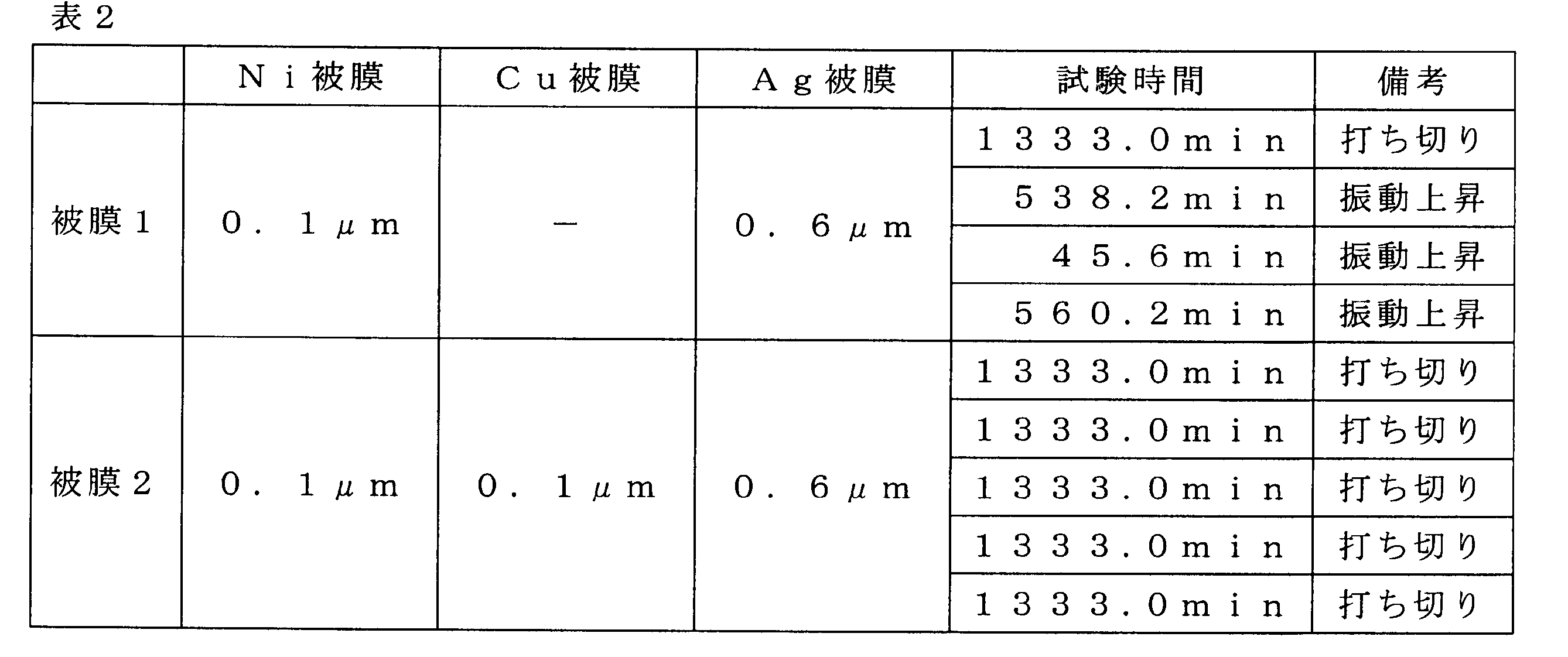
- Test 2 Using the same total ball angular bearing as in Test 1, an Ag coating was formed on all 12 balls. At that time, as shown in Table 2, in the coating 1, only the Ni layer was formed as the underlayer, and in the coating 2, the Ni layer and the Cu layer were formed in this order from the substrate side, and the Ag coating was formed thereon. Both the Ag coating and the underlayer were formed by electroplating, and the thickness of the Ag coating was 0.6 ⁇ m. On the other hand, a Cr film having a thickness of 0.12 ⁇ m was formed on each raceway surface of the inner and outer rings by sputtering.
- test bearing was prepared, and the vibration value was measured under the same conditions using a high temperature rotating test machine in a vacuum shown in FIG.
- the test was performed by preparing four test bearings for the coating 1 and preparing five test bearings for the coating 2. When no increase in vibration was observed at 1333.0 min from the start of rotation, the test was terminated. The results are shown in Table 2.
- the coating 1 consisting only of the Ni layer as the underlayer
- the increase in vibration was observed in the remaining three test bearings in a short time, resulting in a longer life.
- the coating film 2 in which the base layer is composed of two layers of the Ni layer and the Cu layer, no increase in vibration is observed until the test is terminated in all the test bearings, and the life extension is stably achieved. This seems to be because the adhesion of the Ag coating was further improved by interposing the Cu layer between the Ag coating and the Ni layer.
- Test 3 Using the same total ball angular bearing as in Test 1, an Ag coating was formed on all 12 balls. At that time, as shown in Table 3, the thicknesses of the Ag coating and the underlayer were changed, and any coating was formed by electroplating. In addition, the base layer was made into two layers, Ni layer and Cu layer in order from the base-material side. On the other hand, a Cr film having a thickness of 0.12 ⁇ m was formed on each raceway surface of the inner and outer rings by sputtering.
- FIG. 3 is a graph showing the relationship between the total film thickness of the Ag coating and the underlayer and the average life.
- the present invention can improve acoustic characteristics and extend the life of a rolling bearing used in applications requiring high vacuum, high temperature, and no lubrication, and further requiring electrical conductivity.
Abstract
This rolling bearing is configured such that: every one of an inner ring, an outer ring and a rolling body is formed from a steel material; and (A) an Ag coating film is formed on the surface of the rolling body and a Cr coating film is formed on the raceway surface of at least one of the inner ring and the outer ring, or (B) a Cr coating film is formed on the surface of the rolling body and a Cr coating film is formed on the raceway surface of at least one of the inner ring and the outer ring.
Description
本発明は転がり軸受に関し、より詳細には、鋼鉄製の内外輪及び転動体の各表面に、潤滑用の被膜を形成した転がり軸受に関する。
The present invention relates to a rolling bearing, and more particularly to a rolling bearing in which a coating for lubrication is formed on each surface of inner and outer rings made of steel and rolling elements.
例えばX線管球用の転がり軸受は、高真空、高温、無潤滑下で使用され、更には導電性が必要であるため、従来は内外輪の軌道面の表面や転動体の表面にPbを主成分とする固体潤滑被膜を形成している。しかし、Pbは環境への負荷が大きいことから、環境負荷の小さい代替材料の使用が求められている。
For example, a rolling bearing for an X-ray tube is used under high vacuum, high temperature, no lubrication, and further requires electrical conductivity. Conventionally, Pb is applied to the raceway surface of the inner and outer rings and the surface of the rolling element. A solid lubricating film as a main component is formed. However, since Pb has a large environmental load, it is required to use an alternative material with a small environmental load.
代替固体潤滑材料としては、潤滑性や導電性を考慮すると、Agを用いることが考えられる。しかしながら、Agを用いた場合、Agは少なからず相手材に凝着(移着)することが知られている(非特許文献1)。また、AgはPbに比べて硬質な材料であるため、小さな金属塊の移着であっても騒音や振動の原因になりやすい。
As an alternative solid lubricating material, it is conceivable to use Ag in consideration of lubricity and conductivity. However, when Ag is used, it is known that Ag is not a little adhered to (transferred to) the counterpart material (Non-Patent Document 1). Moreover, since Ag is a harder material than Pb, even if a small metal lump is transferred, it is likely to cause noise and vibration.
このようなAgの移着の対策として、特許文献1では、Agの相手材にAgとの溶解度が低い被膜を形成することが記載されており、被膜としてWやTaが挙げられている。
As a countermeasure against such transfer of Ag, Patent Document 1 describes that a film having low solubility with Ag is formed on the Ag counterpart material, and examples of the film include W and Ta.
また、非特許文献2には、各種金属材料の相互溶解度が記載されており、Agとの溶解度が低い材料としてWやNiが挙げられている。
Further, Non-Patent Document 2 describes mutual solubility of various metal materials, and W and Ni are listed as materials having low solubility with Ag.
しかしながら、本発明者による検討の結果、Ag被膜の場合、相手材にNiを被膜しても移着を防止できなかった。また、引用文献1に記載のWも移を防止が十分でないことがあり、改善の余地がある。すなわち、真空下で使用される転がり軸受においては、Agに対する溶解度が低い物質が必ずしも移着し難いとは言えないことが分かった。
However, as a result of studies by the present inventors, in the case of an Ag coating, transfer could not be prevented even if Ni was coated on the counterpart material. In addition, W described in the cited document 1 may not be sufficiently prevented from shifting, and there is room for improvement. That is, it was found that in a rolling bearing used under vacuum, it cannot be said that a substance having a low solubility in Ag is difficult to transfer.
本発明はこのような状況に鑑みてなされたものであり、転動体の表面または内外輪の軌道面に潤滑用のAg被膜を形成した転がり軸受において、Agの相手材への移着を防ぐことにより、音響特性の低下を抑えて、長寿命化を図ることを目的とする。
The present invention has been made in view of such a situation, and in a rolling bearing in which an Ag coating for lubrication is formed on the surface of the rolling element or the raceway surface of the inner and outer rings, the transfer of Ag to the counterpart material is prevented. Therefore, it is an object to suppress the deterioration of the acoustic characteristics and extend the life.
上記課題を解決するために、本発明は下記の転がり軸受を提供する。
(1)内輪、外輪及び転動体が何れも鋼鉄材料からなり、かつ、
前記転動体の表面に、Ag被膜が形成されているとともに、
前記内輪及び前記外輪の少なくとも一方の軌道面に、Cr被膜が形成されていることを特徴とする転がり軸受。
(2)内輪、外輪及び転動体が何れも鋼鉄材料からなり、かつ、
前記転動体の表面に、Cr被膜が形成されているとともに、
前記内輪及び前記外輪の少なくとも一方の軌道面に、Ag被膜が形成されていることを特徴とする転がり軸受。
(3)前記Ag被膜と基材との間に、基材側から順に、Ni層とCu層からなる下地層が介在していることを特徴とする上記(1)または(2)記載の転がり軸受。
(4)前記Ag被膜の膜厚、または前記Ag被膜と前記下地層との合計膜厚が、1.0μm以下であることを特徴とする上記(1)~(3)の何れか1項に記載の転がり軸受。 In order to solve the above problems, the present invention provides the following rolling bearing.
(1) The inner ring, outer ring and rolling element are all made of steel material, and
An Ag coating is formed on the surface of the rolling element,
A rolling bearing, wherein a Cr coating is formed on at least one raceway surface of the inner ring and the outer ring.
(2) The inner ring, outer ring and rolling element are all made of steel material, and
A Cr film is formed on the surface of the rolling element, and
A rolling bearing characterized in that an Ag coating is formed on a raceway surface of at least one of the inner ring and the outer ring.
(3) The rolling described in (1) or (2) above, wherein an underlayer composed of a Ni layer and a Cu layer is interposed between the Ag coating and the substrate in this order from the substrate side. bearing.
(4) In any one of the above (1) to (3), the film thickness of the Ag film or the total film thickness of the Ag film and the base layer is 1.0 μm or less. The rolling bearing described.
本発明によれば、潤滑用にAg被膜を転動体の表面または内外輪の軌道面に形成した転がり軸受において、Ag被膜が相手材に移着するのを防止して、音響特性に優れ、長寿命化を図ることができる。
According to the present invention, in a rolling bearing in which an Ag coating is formed on the surface of the rolling element or the raceway surface of the inner and outer rings for lubrication, the Ag coating is prevented from being transferred to the counterpart material, and has excellent acoustic characteristics, Life can be extended.
以下、本発明に関して図面を参照して詳細に説明する。
Hereinafter, the present invention will be described in detail with reference to the drawings.
本発明の転がり軸受は、転動体及び内外輪を、強度や疲労寿命に優れる軸受鋼、ステンレス鋼、高速鋼等の鋼鉄製とする。具体的には、SUS440CやSUJ2、SKH等が挙げられる。そして、転動体の表面、あるいは内輪の軌道面及び外輪の軌道面の少なくとも一方、好ましくは両軌道面に、潤滑用のAg被膜を形成する。
In the rolling bearing of the present invention, the rolling elements and the inner and outer rings are made of steel such as bearing steel, stainless steel, high-speed steel, etc. that have excellent strength and fatigue life. Specifically, SUS440C, SUJ2, SKH, etc. are mentioned. Then, an Ag coating for lubrication is formed on the surface of the rolling element or at least one of the raceway surface of the inner ring and the raceway surface of the outer ring, preferably on both raceway surfaces.
尚、Cr被膜は、Cr単独の被膜であっても構わないし、Cr合金からなる被膜でも構わないし、CrN(窒化クロム)等でもよい。例えば、CrN(窒化クロム)は反応性スパッタリングやイオンプレーティング法で形成することができる。
The Cr film may be a Cr-only film, a film made of a Cr alloy, CrN (chromium nitride), or the like. For example, CrN (chromium nitride) can be formed by reactive sputtering or ion plating.
また、Cr被膜は複層被膜としてもよい。例えば、基材(転動体または内外輪)から順にNiとCrをそれぞれ成膜することで得られる。複層被膜は本願の効果が達成できる限り、適宜調整してもよい。
The Cr film may be a multilayer film. For example, it can be obtained by depositing Ni and Cr in this order from the base material (rolling element or inner and outer rings). The multilayer coating may be appropriately adjusted as long as the effects of the present application can be achieved.
Cr単独の被膜の場合、Crの含有量は、Cr単独被膜に対して99.0mass%以上が好ましく、より好ましくは99.9mass%以上である。また、残部は不可避不純物となる。
In the case of a Cr-only coating, the Cr content is preferably 99.0 mass% or more, more preferably 99.9 mass% or more with respect to the Cr-only coating. Moreover, the remainder becomes inevitable impurities.
CrN(窒化クロム)の含有量は、CrN(窒化クロム)被膜に対して99.0mass%以上が好ましく、より好ましくは99.8mass%以上である。また、残部は不可避不純物となる。
The content of CrN (chromium nitride) is preferably 99.0 mass% or more, more preferably 99.8 mass% or more with respect to the CrN (chromium nitride) coating. Moreover, the remainder becomes inevitable impurities.
Cr合金とした場合は、Crとの合金成分として、Ni、Co、Fe、Mo等を挙げることができ、合金成分は2種以上でもよい。この際のCrの含有量はCr合金被膜に対して15mass%以上が好ましく、より好ましくは30mass%以上である。また、残部は合金成分と不可避不純物となる。
In the case of Cr alloy, Ni, Co, Fe, Mo and the like can be mentioned as alloy components with Cr, and two or more alloy components may be used. In this case, the Cr content is preferably 15 mass% or more, more preferably 30 mass% or more with respect to the Cr alloy coating. Further, the balance becomes alloy components and inevitable impurities.
また、転動体にAg被膜を形成した場合は、軌道面にCr被膜を形成する。あるいは、内外輪の軌道輪にAg被膜を形成した場合は、転動体の表面にCr被膜を形成する。このような被膜の組み合わせにより、Agの相手材への移着を防止することができ、初期の平滑な表面が保たれて、長期にわたり音響特性に優れるようになる。
Also, when an Ag coating is formed on the rolling elements, a Cr coating is formed on the raceway surface. Alternatively, when an Ag coating is formed on the inner and outer races, a Cr coating is formed on the surface of the rolling element. By such a combination of coatings, the transfer of Ag to the counterpart material can be prevented, the initial smooth surface can be maintained, and the acoustic characteristics can be improved over a long period of time.
更には、Ag被膜と基材(転動体または内外輪)との密着性を高めるために、下地層を介在させることが好ましい。下地層としては、基材側から順に、Ni層とCu層とを積層したものである。後述する試験2に示すように、Ni層のみではAg被膜の密着性が不十分である。
Furthermore, it is preferable to interpose a base layer in order to improve the adhesion between the Ag coating and the base material (rolling element or inner / outer ring). As an underlayer, a Ni layer and a Cu layer are laminated in order from the substrate side. As shown in Test 2 to be described later, the adhesion of the Ag coating is insufficient only with the Ni layer.
Ag被膜及びCr被膜の形成方法としては、被膜を均一に形成できることに加えて、膜厚の制御も容易であることが好ましく、例えばスパッタリング法やイオンプレーティング法、めっき法により形成することができる。尚、Cr被膜では、スパッタリング法で形成した場合、大気に曝した時点で酸素と結合して表面エネルギーが小さい安定した状態になり、移着防止効果に優れるようになる。
As a method for forming the Ag film and the Cr film, in addition to being able to form the film uniformly, it is preferable that the film thickness is easily controlled. For example, it can be formed by sputtering, ion plating, or plating. . In addition, when the Cr coating is formed by a sputtering method, when it is exposed to the atmosphere, it is combined with oxygen and becomes a stable state with a small surface energy, and is excellent in the effect of preventing transfer.
また、Ag被膜及びCr被膜、下地層は何れも、厚すぎると被膜が剥離しやすくなり、軸受の回転に支障を来すおそれがある。一方、薄すぎると、被膜が均一に形成されず、未被膜の部分が発生することも懸念される。特に、Ag被膜は軸受の潤滑を担うため、適度の膜厚を必要とする。そのため、Ag被膜の膜厚、あるいはAg被膜と下地層との合計膜厚の上限は1.0μm以下が好ましく、0.7μm以下がより好ましい。Ag被膜の膜厚、あるいはAg被膜と下地層との合計膜厚の下限は0.2μm以上が好ましく、0.4μm以上がより好ましい。
Also, if the Ag coating, Cr coating, and underlayer are all too thick, the coating tends to peel off, which may hinder the rotation of the bearing. On the other hand, if it is too thin, the film is not formed uniformly, and there is a concern that an uncoated part is generated. In particular, since the Ag coating is responsible for lubricating the bearing, an appropriate film thickness is required. Therefore, the upper limit of the film thickness of the Ag film or the total film thickness of the Ag film and the base layer is preferably 1.0 μm or less, and more preferably 0.7 μm or less. The lower limit of the thickness of the Ag coating or the total thickness of the Ag coating and the base layer is preferably 0.2 μm or more, and more preferably 0.4 μm or more.
下地層としてNiとCuを積層する場合、それぞれの膜厚は以下のようにするのが好ましい。
・Niの膜厚は0.05~0.2μmが好ましく、より好ましくは0.05~0.15μmである。
・Cuの膜厚は0.05~0.2μmが好ましく、より好ましくは0.05~0.15μmである。
・Agの膜厚は0.1~0.6μmが好ましく、より好ましくは0.2~0.5μmである。 When Ni and Cu are laminated as the underlayer, the respective film thicknesses are preferably as follows.
The film thickness of Ni is preferably 0.05 to 0.2 μm, more preferably 0.05 to 0.15 μm.
The film thickness of Cu is preferably 0.05 to 0.2 μm, more preferably 0.05 to 0.15 μm.
The film thickness of Ag is preferably 0.1 to 0.6 μm, more preferably 0.2 to 0.5 μm.
また、Ni、Cu、Agの各含有量は、以下の通りである。
・Niの含有量は、Ni被膜に対して99.0mass%以上が好ましく、より好ましくは99.9mass%以上である。また、残部は不可避不純物となる。
・Cuの含有量は、Cu被膜に対して99.0mass%以上が好ましく、より好ましくは99.9mass%以上である。また、残部は不可避不純物となる。
・Agの含有量は、Ag被膜に対して99.0mass%以上が好ましく、より好ましくは99.9mass%以上である。また、残部は不可避不純物となる。 Moreover, each content of Ni, Cu, and Ag is as follows.
-99.0 mass% or more is preferable with respect to Ni film, and, as for content of Ni, More preferably, it is 99.9 mass% or more. Moreover, the remainder becomes inevitable impurities.
-99.0 mass% or more is preferable with respect to Cu coating, and, as for content of Cu, More preferably, it is 99.9 mass% or more. Moreover, the remainder becomes inevitable impurities.
-99.0 mass% or more is preferable with respect to Ag film, and, as for content of Ag, More preferably, it is 99.9 mass% or more. Moreover, the remainder becomes inevitable impurities.
また、Ag被膜には適宜添加剤などを添加しても良い。添加剤と併用する際は、Agの含有量は90mass%以上とすればよい。また、残部は併用した添加剤と不可避不純物となる。
Further, additives and the like may be added as appropriate to the Ag coating. When used in combination with an additive, the content of Ag may be 90 mass% or more. In addition, the balance becomes the additive and inevitable impurities used together.
一方、Cr被膜の膜厚は、0.05~1.0μmが好ましく、0.05~0.15μmがより好ましい。
On the other hand, the film thickness of the Cr coating is preferably 0.05 to 1.0 μm, more preferably 0.05 to 0.15 μm.
尚、Agは大気中で表面に極薄い酸化膜を形成する場合があり、酸化膜により潤滑性が低下することが懸念される。この酸化問題を解決するために、Ag膜の表面に、軟質金属からなる酸化防止被膜を追加してもよい。軟質金属としては、Agとの密着性がよく、かつ、Agよりもイオン化傾向が大きいTiやIn、Sn、Mg、Zn、Al等が好ましく、良好な酸化防止効果が得られる。特に、InやSnは、潤滑性も期待できるため好ましい。
Incidentally, Ag may form an extremely thin oxide film on the surface in the atmosphere, and there is a concern that the lubricity may be lowered by the oxide film. In order to solve this oxidation problem, an antioxidant coating made of a soft metal may be added to the surface of the Ag film. As the soft metal, Ti, In, Sn, Mg, Zn, Al, or the like, which has good adhesion with Ag and has a higher ionization tendency than Ag, is preferable, and a good antioxidant effect is obtained. In particular, In and Sn are preferable because lubricity can be expected.
酸化防止被膜の成膜方法としてスパッタリングやメッキ等が挙げられるが、酸化防止被膜が厚すぎると振動の原因になるため、膜厚を100nm以下にすることが好ましく、膜厚の調整を行う必要がある。また、100nm以下であれば、使用中に速やかに酸化防止被膜が剥れるため、潤滑性に優れたAgによる潤滑が得られる。尚、Agは酸化しやすいため、酸化防止被膜の形成前に還元処理を施すことが好ましい。
Sputtering, plating, and the like can be cited as a method for forming the antioxidant coating. However, if the antioxidant coating is too thick, it causes vibrations. Therefore, the film thickness is preferably 100 nm or less, and it is necessary to adjust the film thickness. is there. On the other hand, when the thickness is 100 nm or less, the antioxidant coating is quickly peeled off during use, so that lubrication with Ag having excellent lubricity can be obtained. In addition, since Ag is easy to oxidize, it is preferable to perform a reduction process before formation of an antioxidant film.
本発明では、Ag被膜が固体潤滑被膜として作用するため、潤滑油やグリースを使用できない用途でも潤滑性を付与することができる。また、Ag被膜及びCr被膜は共に導電性に優れる。そのため、本発明の転がり軸受は、高真空、高温で使用され、導電性も要求されるX線管球用軸受として好適である。
In the present invention, since the Ag coating acts as a solid lubricating coating, lubricity can be imparted even in applications where lubricating oil or grease cannot be used. Further, both the Ag coating and the Cr coating are excellent in conductivity. Therefore, the rolling bearing of the present invention is suitable as an X-ray tube bearing that is used at high vacuum and high temperature and also requires electrical conductivity.
X線管用軸受には制限は無く、図1にその一例を示す。図示されるように、一対の総玉軸受11,11が回転軸20に回転可能に軸支されている。外輪30,30は、ハウジング7に対しすきま嵌めにて嵌合され、ハウジング7に対し軸方向の移動が可能なように配置されている。両総玉軸受11,11は、外輪軌道面31,31と回転軸20に直接形成された内輪軌道面21,21との間に、多数の玉40,40を介在させた所謂「インテグラル式深溝玉軸受」となっている。玉40、40にはAg被膜が形成され、外輪軌道面31,31及び内輪軌道面21,21にはCr被膜が形成されている。あるいは、玉40、40にCr被膜が形成され、外輪軌道面31,31及び内輪軌道面21,21にAg被膜が形成されていてもよい。更には、Ag被膜は、Ni層とCu層とからなる下地層を介して形成されていてもよい。また、符号8はターゲット板である。
¡There are no restrictions on X-ray tube bearings. An example is shown in FIG. As shown in the drawing, a pair of ball bearings 11, 11 are rotatably supported on the rotary shaft 20. The outer rings 30, 30 are fitted to the housing 7 by a clearance fit and are arranged so as to be movable in the axial direction with respect to the housing 7. Both the total ball bearings 11, 11 are so-called “integral type” in which a large number of balls 40, 40 are interposed between the outer ring raceway surfaces 31, 31 and the inner ring raceway surfaces 21, 21 formed directly on the rotary shaft 20. "Deep groove ball bearing". Ag balls are formed on the balls 40, 40, and Cr coatings are formed on the outer ring raceway surfaces 31, 31 and the inner ring raceway surfaces 21, 21. Alternatively, a Cr coating may be formed on the balls 40, 40, and an Ag coating may be formed on the outer ring raceway surfaces 31, 31 and the inner ring raceway surfaces 21, 21. Furthermore, the Ag film may be formed through an underlayer composed of a Ni layer and a Cu layer. Reference numeral 8 denotes a target plate.
尚、回転軸20の内輪軌道面21,21を含む外周面、及び外輪軌道面31,31を含む内周面に熱伝導促進膜を形成してもよい。更にはカラー32,33の内周面にも、同じく熱伝導促進膜を形成すれば、より熱伝導効率が向上する。
In addition, you may form a heat conduction promotion film | membrane in the outer peripheral surface containing the inner ring raceway surfaces 21 and 21 of the rotating shaft 20, and the inner peripheral surface containing the outer ring raceway surfaces 31 and 31. Furthermore, if a heat conduction promoting film is also formed on the inner peripheral surfaces of the collars 32 and 33, the heat conduction efficiency is further improved.
軸受の種類にも制限はなく、図1ではインテグラル式深溝玉軸受であるが、回転軸と内輪を別体にしても良いし、他にもアンギュラ玉軸受やころ軸受等にも適用できる。
There is no limitation on the type of bearing. In FIG. 1, an integral type deep groove ball bearing is used. However, the rotary shaft and the inner ring may be separated, and the present invention can also be applied to angular ball bearings and roller bearings.
上記より、本発明は下記構成であることがより好ましい。
・軸受形式について
本発明はインテグラル式の玉軸受もしくは深溝玉軸受、アンギュラ玉軸受などの玉軸受に適用することが好ましい。
・母材について
玉の材質は、SUS440CまたはSUJ2またはSKH4が好ましい。外輪および内輪の材質は、SUS440CまたはSUJ2またはSKH4が好ましい。尚、これら鋼材の成分は、SUS440CはJIS G 4303(2012),SUJ2はJIS G 4805(2008),SKH4はJIS G 4403(2015)に従う。
・玉の被膜
電気めっき法により,基材側から順に、Niめっき0.05~0.15μm、Cuめっき0.05~0.15μm、Agめっき0.2 ~0.5μmを形成することが好ましい。また,NiめっきとCuめっきとAgめっきとの合計は、0.4 ~0.7μmとするのが好ましい。更に、NiめっきのNiの含有量は99.9mass%以上、CuめっきのCuの含有量は99.9mass%以上、AgめっきのAgの含有量は99.9mass%以上がそれぞれ好ましく、残部は何れも不可避不純物となる。
・外輪の被膜
スパッタリング法により,Crからなる被膜0.05~0.15μmを形成することが好ましい。Cr被膜のCrの含有量は99.9mass%以上が好ましく、残部は不可避不純物となる。
・内輪の被膜
スパッタリング法により,Crからなる被膜0.05~0.15μmを形成することが好ましい。Cr被膜のCrの含有量は99.9mass%以上が好ましく、残部は不可避不純物となる。 From the above, the present invention preferably has the following configuration.
Bearing type The present invention is preferably applied to ball bearings such as integral type ball bearings, deep groove ball bearings, and angular ball bearings.
-About a base material As for the material of a ball, SUS440C or SUJ2 or SKH4 is preferable. The material of the outer ring and the inner ring is preferably SUS440C, SUJ2, or SKH4. The components of these steel materials are in accordance with JIS G 4303 (2012) for SUS440C, JIS G 4805 (2008) for SUJ2, and JIS G 4403 (2015) for SKH4.
Ball coating It is preferable to form Ni plating 0.05 to 0.15 μm, Cu plating 0.05 to 0.15 μm, and Ag plating 0.2 to 0.5 μm in order from the substrate side by electroplating. . The total of the Ni plating, Cu plating and Ag plating is preferably 0.4 to 0.7 μm. Further, the Ni content of the Ni plating is preferably 99.9 mass% or more, the Cu content of the Cu plating is preferably 99.9 mass% or more, and the Ag content of the Ag plating is preferably 99.9 mass% or more, and the remainder is any Is also an inevitable impurity.
-Coating of outer ring It is preferable to form a film made of Cr of 0.05 to 0.15 μm by sputtering. The Cr content of the Cr coating is preferably 99.9 mass% or more, and the remainder is an inevitable impurity.
-Inner ring film It is preferable to form a film made of Cr of 0.05 to 0.15 μm by sputtering. The Cr content of the Cr coating is preferably 99.9 mass% or more, and the remainder is an inevitable impurity.
以下に実施例を挙げて本発明を更に説明するが、本発明はこれにより何ら制限されるものではなない。
Hereinafter, the present invention will be further described with reference to examples, but the present invention is not limited thereto.
(試験1)
内輪、外輪及び玉(転動体)からなる、呼び番号7200Aの総玉アンギュラ軸受(内径10mm、外径30mm、幅9mm、接触角α=30°、玉数12個、玉径3/16インチ)を用意した。尚、内輪及び外輪はSUJ2製であり、玉はSUS440C製またはSUJ2製である、そして、12個の中で等間隔で4個の玉の表面にAg被膜を形成し、残り8個は被膜無しとした。Ag被膜は、何れも電気めっき法により、基材側からNi層,Cu層の順で下地層を形成し、その上にAg被膜を形成した。尚、Ni被膜の膜厚は0.1μm、Cu被膜の膜厚は0.1μm、Ag被膜の膜厚は0.3μmとした。また、内輪及び外輪の各軌道面には、スパッタリング法または電気めっき法により、表1に示す金属被膜を形成した。そして、これら玉及び内外輪を用いてアンギュラ玉軸受を組み立て、試験軸受とした。 (Test 1)
Total ball angular bearing of nominal number 7200A consisting of inner ring, outer ring and ball (rolling element) (inner diameter 10 mm, outer diameter 30 mm, width 9 mm, contact angle α = 30 °, 12 balls, ball diameter 3/16 inch) Prepared. The inner ring and the outer ring are made of SUJ2, the balls are made of SUS440C or SUJ2, and an Ag coating is formed on the surface of four balls at equal intervals in 12 pieces, and the remaining 8 pieces have no coating. It was. As for the Ag coating, an undercoat layer was formed in the order of the Ni layer and the Cu layer from the base material side by the electroplating method, and the Ag coating was formed thereon. The film thickness of the Ni film was 0.1 μm, the film thickness of the Cu film was 0.1 μm, and the film thickness of the Ag film was 0.3 μm. Moreover, the metal film shown in Table 1 was formed in each raceway surface of an inner ring | wheel and an outer ring | wheel by the sputtering method or the electroplating method. Then, an angular ball bearing was assembled using these balls and inner and outer rings to obtain a test bearing.
内輪、外輪及び玉(転動体)からなる、呼び番号7200Aの総玉アンギュラ軸受(内径10mm、外径30mm、幅9mm、接触角α=30°、玉数12個、玉径3/16インチ)を用意した。尚、内輪及び外輪はSUJ2製であり、玉はSUS440C製またはSUJ2製である、そして、12個の中で等間隔で4個の玉の表面にAg被膜を形成し、残り8個は被膜無しとした。Ag被膜は、何れも電気めっき法により、基材側からNi層,Cu層の順で下地層を形成し、その上にAg被膜を形成した。尚、Ni被膜の膜厚は0.1μm、Cu被膜の膜厚は0.1μm、Ag被膜の膜厚は0.3μmとした。また、内輪及び外輪の各軌道面には、スパッタリング法または電気めっき法により、表1に示す金属被膜を形成した。そして、これら玉及び内外輪を用いてアンギュラ玉軸受を組み立て、試験軸受とした。 (Test 1)
Total ball angular bearing of nominal number 7200A consisting of inner ring, outer ring and ball (rolling element) (
上記の試験軸受を、図2に示す真空中高温回転試験機に取り付け、回転試験を行った。
この試験機は、試験軸受Jで支持される回転軸Sと、回転軸Sを回転するモータMと、回転軸Sを加熱するヒータHと、真空室を形成するフランジS1および壁S2,S3と、試験軸受Jの温度を検出する熱電対(図示せず)とを備えている。回転軸Sは、試験軸受J以外に符号18で示す軸受によっても支持されている。 The test bearing described above was attached to a high-temperature rotation tester in vacuum shown in FIG. 2 and a rotation test was performed.
This testing machine includes a rotating shaft S supported by a test bearing J, a motor M that rotates the rotating shaft S, a heater H that heats the rotating shaft S, a flange S1 that forms a vacuum chamber, and walls S2 and S3. And a thermocouple (not shown) for detecting the temperature of the test bearing J. The rotating shaft S is also supported by a bearing indicated byreference numeral 18 in addition to the test bearing J.
この試験機は、試験軸受Jで支持される回転軸Sと、回転軸Sを回転するモータMと、回転軸Sを加熱するヒータHと、真空室を形成するフランジS1および壁S2,S3と、試験軸受Jの温度を検出する熱電対(図示せず)とを備えている。回転軸Sは、試験軸受J以外に符号18で示す軸受によっても支持されている。 The test bearing described above was attached to a high-temperature rotation tester in vacuum shown in FIG. 2 and a rotation test was performed.
This testing machine includes a rotating shaft S supported by a test bearing J, a motor M that rotates the rotating shaft S, a heater H that heats the rotating shaft S, a flange S1 that forms a vacuum chamber, and walls S2 and S3. And a thermocouple (not shown) for detecting the temperature of the test bearing J. The rotating shaft S is also supported by a bearing indicated by
回転軸SのモータM側端部は、カップリング10により、磁気的シールユニット16の回転軸の一端に接続しており、磁気的シールユニット16の回転軸の他端は、カップリング17によりモータMに接続している。また、磁気的シールユニット16、カップリング17及びモータMはハウジング(図示せず)に収容され、大気中に設置される。
The end of the rotating shaft S on the motor M side is connected to one end of the rotating shaft of the magnetic seal unit 16 by the coupling 10, and the other end of the rotating shaft of the magnetic seal unit 16 is connected to the motor by the coupling 17. Connected to M. The magnetic seal unit 16, the coupling 17, and the motor M are accommodated in a housing (not shown) and are installed in the atmosphere.
そして、アキシャル荷重:30N、回転速度:4500min-1、温度:25℃、真空度:3×10⁻³Paにて、試験軸受Jを回転させ、真空室のフランジS1の面に設置した加速度ピックアップにより振動値を測定した。初期振動値の5倍(25m/s2)を超えるまでの時間を計測し、表1に「振動上昇までの時間」として示した。
Then, the test bearing J was rotated at an axial load of 30 N, a rotational speed of 4500 min −1 , a temperature of 25 ° C., and a degree of vacuum of 3 × 10 −3 Pa, and an acceleration pickup installed on the flange S1 surface of the vacuum chamber The vibration value was measured by The time required to exceed 5 times the initial vibration value (25 m / s 2 ) was measured, and is shown in Table 1 as “Time until vibration rise”.

実施例1のように、一方にAg被膜を形成し、相手材にCr被膜を形成することにより、Agの移着が生じないことから振動が上昇せず、他の金属を用いた比較例に比べて大幅な長寿命化が図られている。特に、比較例5は、特許文献1で挙げられているAgとWとの組み合わせであるが、実施例1のAgとCrとの組み合わせに比べて10分の1程度の寿命しか得られていない。
As in Example 1, by forming an Ag film on one side and forming a Cr film on the counterpart material, no transfer of Ag occurs, so vibration does not increase, and in a comparative example using another metal Compared to this, the service life is greatly extended. In particular, Comparative Example 5 is a combination of Ag and W listed in Patent Document 1, but only about one-tenth of the lifetime is obtained as compared with the combination of Ag and Cr in Example 1. .
(試験2)
試験1と同一の総玉アンギュラ軸受を用い、12個全ての玉にAg被膜を形成した。その際、表2に示すように被膜1では下地層としてNi層のみ、被膜2では基材側から順にNi層、Cu層の2層を形成し、その上にAg被膜を形成した。Ag被膜及び下地層ともに、電気めっき法で形成し、Ag被膜の膜厚は0.6μmとした。一方、内外輪の各軌道面には、スパッタリング法によりCr被膜を0.12μmの厚さで形成した。 (Test 2)
Using the same total ball angular bearing as inTest 1, an Ag coating was formed on all 12 balls. At that time, as shown in Table 2, in the coating 1, only the Ni layer was formed as the underlayer, and in the coating 2, the Ni layer and the Cu layer were formed in this order from the substrate side, and the Ag coating was formed thereon. Both the Ag coating and the underlayer were formed by electroplating, and the thickness of the Ag coating was 0.6 μm. On the other hand, a Cr film having a thickness of 0.12 μm was formed on each raceway surface of the inner and outer rings by sputtering.
試験1と同一の総玉アンギュラ軸受を用い、12個全ての玉にAg被膜を形成した。その際、表2に示すように被膜1では下地層としてNi層のみ、被膜2では基材側から順にNi層、Cu層の2層を形成し、その上にAg被膜を形成した。Ag被膜及び下地層ともに、電気めっき法で形成し、Ag被膜の膜厚は0.6μmとした。一方、内外輪の各軌道面には、スパッタリング法によりCr被膜を0.12μmの厚さで形成した。 (Test 2)
Using the same total ball angular bearing as in
そして、試験軸受を作製し、図2に示した真空中高温回転試験機を用いて同条件にて振動値を測定し、寿命を求めた。試験は、被膜1については4つの試験軸受を作製して行い、被膜2については5個の試験軸受を作製して行った。尚、回転開始から1333.0minの時点で振動上昇が見られなかった場合は、試験を打ち切った。結果を表2に示す。
Then, a test bearing was prepared, and the vibration value was measured under the same conditions using a high temperature rotating test machine in a vacuum shown in FIG. The test was performed by preparing four test bearings for the coating 1 and preparing five test bearings for the coating 2. When no increase in vibration was observed at 1333.0 min from the start of rotation, the test was terminated. The results are shown in Table 2.
下地層としてNi層のみとした被膜1では、一つの試験軸受では試験打ち切りまで振動上昇が見らなかったものの、残りの3個の試験軸受では短時間で振動上昇が見られており、寿命に大きなばらつきがあった。これに対し、下地層をNi層とCu層との2層で構成した被膜2では、全ての試験軸受で試験打ち切りまで振動上昇が見られず、長寿命化が安定して図られている。これは、Ag被膜とNi層との間にCu層を介在させたことにより、Ag被膜の密着性がより向上したためと思われる。
With the coating 1 consisting only of the Ni layer as the underlayer, although no increase in vibration was observed until the test was terminated in one test bearing, the increase in vibration was observed in the remaining three test bearings in a short time, resulting in a longer life. There was a big variation. On the other hand, in the coating film 2 in which the base layer is composed of two layers of the Ni layer and the Cu layer, no increase in vibration is observed until the test is terminated in all the test bearings, and the life extension is stably achieved. This seems to be because the adhesion of the Ag coating was further improved by interposing the Cu layer between the Ag coating and the Ni layer.
(試験3)
試験1と同一の総玉アンギュラ軸受を用い、12個全ての玉にAg被膜を形成した。その際、表3に示すようにAg被膜及び下地層の各膜厚を変え、何れの被膜も電気めっき法で形成した。尚、下地層は、基材側から順にNi層、Cu層の2層とした。一方、内外輪の各軌道面には、スパッタリング法によりCr被膜を0.12μmの厚さで形成した。 (Test 3)
Using the same total ball angular bearing as inTest 1, an Ag coating was formed on all 12 balls. At that time, as shown in Table 3, the thicknesses of the Ag coating and the underlayer were changed, and any coating was formed by electroplating. In addition, the base layer was made into two layers, Ni layer and Cu layer in order from the base-material side. On the other hand, a Cr film having a thickness of 0.12 μm was formed on each raceway surface of the inner and outer rings by sputtering.
試験1と同一の総玉アンギュラ軸受を用い、12個全ての玉にAg被膜を形成した。その際、表3に示すようにAg被膜及び下地層の各膜厚を変え、何れの被膜も電気めっき法で形成した。尚、下地層は、基材側から順にNi層、Cu層の2層とした。一方、内外輪の各軌道面には、スパッタリング法によりCr被膜を0.12μmの厚さで形成した。 (Test 3)
Using the same total ball angular bearing as in
そして、試験軸受を作製し、図2に示した真空中高温回転試験機を用いて同条件にて振動値を測定し、寿命を求めた。各被膜とも試験軸受の数が異なるが、平均寿命を表3に示す。また、図3に、Ag被膜と下地層との合計膜厚と、平均寿命との関係をグラフにして示す。
Then, a test bearing was prepared, and the vibration value was measured under the same conditions using a high temperature rotating test machine in a vacuum shown in FIG. Although the number of test bearings is different for each coating, the average life is shown in Table 3. FIG. 3 is a graph showing the relationship between the total film thickness of the Ag coating and the underlayer and the average life.

表3及び図3に示すように、合計膜厚が1.0μmを超えると寿命が極端に短くなっている。これは、被膜が厚すぎると、玉同士の接触の際に凹凸が形成されて振動上昇が生じたことが原因であると考えられる。
As shown in Table 3 and FIG. 3, when the total film thickness exceeds 1.0 μm, the life is extremely shortened. It is considered that this is because, when the coating is too thick, unevenness is formed when the balls are brought into contact with each other, resulting in an increase in vibration.
本発明を詳細にまた特定の実施態様を参照して説明したが、本発明の精神と範囲を逸脱することなく様々な変更や修正を加えることができることは当業者にとって明らかである。
本出願は、2017年2月2日出願の日本特許出願(特願2017-17773)に基づくものであり、その内容はここに参照として取り込まれる。 Although the present invention has been described in detail and with reference to specific embodiments, it will be apparent to those skilled in the art that various changes and modifications can be made without departing from the spirit and scope of the invention.
This application is based on a Japanese patent application filed on Feb. 2, 2017 (Japanese Patent Application No. 2017-17773), the contents of which are incorporated herein by reference.
本発明は、高真空、高温、無潤滑下で使用され、更には導電性が要求される用途に使用される転がり軸受において、音響特性の向上や、長寿命化を図ることができる。
DETAILED DESCRIPTION OF THE INVENTION The present invention can improve acoustic characteristics and extend the life of a rolling bearing used in applications requiring high vacuum, high temperature, and no lubrication, and further requiring electrical conductivity.
7 ハウジング
8 ターゲット板
11 総玉軸受
20 回転軸
21 内輪軌道面
30 外輪
31 外輪軌道面
40 玉 7Housing 8 Target plate 11 Full ball bearing 20 Rotating shaft 21 Inner ring raceway surface 30 Outer ring 31 Outer ring raceway surface 40
8 ターゲット板
11 総玉軸受
20 回転軸
21 内輪軌道面
30 外輪
31 外輪軌道面
40 玉 7
Claims (4)
- 内輪、外輪及び転動体が何れも鋼鉄材料からなり、かつ、
前記転動体の表面に、Ag被膜が形成されているとともに、
前記内輪及び前記外輪の少なくとも一方の軌道面に、Cr被膜が形成されていることを特徴とする転がり軸受。 The inner ring, outer ring and rolling element are all made of steel material, and
An Ag coating is formed on the surface of the rolling element,
A rolling bearing, wherein a Cr coating is formed on at least one raceway surface of the inner ring and the outer ring. - 内輪、外輪及び転動体が何れも鋼鉄材料からなり、かつ、
前記転動体の表面に、Cr被膜が形成されているとともに、
前記内輪及び前記外輪の少なくとも一方の軌道面に、Ag被膜が形成されていることを特徴とする転がり軸受。 The inner ring, outer ring and rolling element are all made of steel material, and
A Cr film is formed on the surface of the rolling element, and
A rolling bearing characterized in that an Ag coating is formed on a raceway surface of at least one of the inner ring and the outer ring. - 前記Ag被膜と基材との間に、基材側から順に、Ni層とCu層からなる下地層が介在していることを特徴とする請求項1または2記載の転がり軸受。 The rolling bearing according to claim 1 or 2, wherein an underlayer composed of a Ni layer and a Cu layer is interposed between the Ag coating and the base material in this order from the base material side.
- 前記Ag被膜の膜厚、または前記Ag被膜と前記下地層との合計膜厚が、1.0μm以下であることを特徴とする請求項1~3の何れか1項に記載の転がり軸受。 The rolling bearing according to any one of claims 1 to 3, wherein a film thickness of the Ag film or a total film thickness of the Ag film and the base layer is 1.0 µm or less. *
Priority Applications (4)
| Application Number | Priority Date | Filing Date | Title |
|---|---|---|---|
| US16/337,578 US10995798B2 (en) | 2017-02-02 | 2018-01-29 | Rolling bearing |
| EP18748460.5A EP3578839B1 (en) | 2017-02-02 | 2018-01-29 | Rolling bearing |
| JP2018533959A JP6481798B2 (en) | 2017-02-02 | 2018-01-29 | Rolling bearing |
| CN201880009906.6A CN110249146A (en) | 2017-02-02 | 2018-01-29 | Rolling bearing |
Applications Claiming Priority (2)
| Application Number | Priority Date | Filing Date | Title |
|---|---|---|---|
| JP2017017773 | 2017-02-02 | ||
| JP2017-017773 | 2017-02-02 |
Publications (1)
| Publication Number | Publication Date |
|---|---|
| WO2018143138A1 true WO2018143138A1 (en) | 2018-08-09 |
Family
ID=63039766
Family Applications (1)
| Application Number | Title | Priority Date | Filing Date |
|---|---|---|---|
| PCT/JP2018/002808 WO2018143138A1 (en) | 2017-02-02 | 2018-01-29 | Rolling bearing |
Country Status (5)
| Country | Link |
|---|---|
| US (1) | US10995798B2 (en) |
| EP (1) | EP3578839B1 (en) |
| JP (2) | JP6481798B2 (en) |
| CN (1) | CN110249146A (en) |
| WO (1) | WO2018143138A1 (en) |
Families Citing this family (2)
| Publication number | Priority date | Publication date | Assignee | Title |
|---|---|---|---|---|
| JP2022055432A (en) * | 2020-09-29 | 2022-04-08 | 株式会社ジェイテクト | Bearing device and rotating device using bearing device |
| CN117570118A (en) * | 2024-01-17 | 2024-02-20 | 苏州长城精工科技股份有限公司 | Coupling bearing structure of CT bulb tube |
Citations (8)
| Publication number | Priority date | Publication date | Assignee | Title |
|---|---|---|---|---|
| JPS5842829A (en) * | 1981-09-09 | 1983-03-12 | Hitachi Ltd | Solid lubrication rolling bearing |
| JPS5992219U (en) * | 1982-12-15 | 1984-06-22 | 日本精工株式会社 | rolling bearing |
| JPS634424U (en) * | 1986-06-26 | 1988-01-12 | ||
| JPH0532651U (en) | 1991-09-27 | 1993-04-30 | ワイケイケイアーキテクチユラルプロダクツ株式会社 | Folding door opening and fixing device |
| JPH09177774A (en) * | 1995-12-27 | 1997-07-11 | Ntn Corp | Tapered roller bearing |
| JP2001254801A (en) * | 2000-03-08 | 2001-09-21 | Mitsubishi Heavy Ind Ltd | Machine element utilizing rolling friction, its rolling body and linear introduction mechanism for vacuum |
| JP2014022339A (en) * | 2012-07-24 | 2014-02-03 | Hitachi Medical Corp | X-ray tube device and x-ray ct device |
| JP2017017773A (en) | 2015-06-26 | 2017-01-19 | ミネベア株式会社 | Hybrid type stepping motor |
Family Cites Families (14)
| Publication number | Priority date | Publication date | Assignee | Title |
|---|---|---|---|---|
| FR1461335A (en) * | 1963-01-14 | 1966-02-25 | Loire Atel Forges | Process for the treatment of surfaces of metal parts allowing operations without lubrication |
| JPS495586A (en) * | 1972-04-06 | 1974-01-18 | ||
| JPS58113629A (en) * | 1981-12-25 | 1983-07-06 | Koyo Seiko Co Ltd | Rolling bearing |
| JPS5992219A (en) * | 1982-11-16 | 1984-05-28 | Toyota Motor Corp | Indicating method of optimum gear position of vehicle |
| KR100350937B1 (en) * | 1993-12-28 | 2002-12-11 | 가부시키가이샤 후지킨 | Sliding parts and manufacturing method |
| JPH07301241A (en) * | 1994-04-28 | 1995-11-14 | Ntn Corp | Anticorrosive bearing |
| JPH09161698A (en) * | 1995-12-14 | 1997-06-20 | Toshiba Corp | Rotating anode x-ray tube |
| CN2435562Y (en) * | 2000-05-22 | 2001-06-20 | 吕红玉 | High-temp. oilless lubrication bearing |
| JP2002195276A (en) * | 2000-12-27 | 2002-07-10 | Nsk Ltd | Rolling bearing |
| JP2006266314A (en) * | 2005-03-22 | 2006-10-05 | Ntn Corp | Rolling bearing for transmission of automobile |
| JP2008243694A (en) * | 2007-03-28 | 2008-10-09 | Jtekt Corp | Rolling bearing for x-ray tube and x-ray tube apparatus |
| JP5019445B2 (en) * | 2007-09-05 | 2012-09-05 | 株式会社不二越 | Low friction sliding member and low friction rolling member |
| JP2011208745A (en) * | 2010-03-30 | 2011-10-20 | Ntn Corp | Rolling bearing |
| JP5905681B2 (en) * | 2011-08-23 | 2016-04-20 | Ntn株式会社 | Rolling bearing |
-
2018
- 2018-01-29 WO PCT/JP2018/002808 patent/WO2018143138A1/en unknown
- 2018-01-29 CN CN201880009906.6A patent/CN110249146A/en active Pending
- 2018-01-29 JP JP2018533959A patent/JP6481798B2/en active Active
- 2018-01-29 US US16/337,578 patent/US10995798B2/en active Active
- 2018-01-29 EP EP18748460.5A patent/EP3578839B1/en active Active
-
2019
- 2019-02-14 JP JP2019024543A patent/JP2019082256A/en active Pending
Patent Citations (8)
| Publication number | Priority date | Publication date | Assignee | Title |
|---|---|---|---|---|
| JPS5842829A (en) * | 1981-09-09 | 1983-03-12 | Hitachi Ltd | Solid lubrication rolling bearing |
| JPS5992219U (en) * | 1982-12-15 | 1984-06-22 | 日本精工株式会社 | rolling bearing |
| JPS634424U (en) * | 1986-06-26 | 1988-01-12 | ||
| JPH0532651U (en) | 1991-09-27 | 1993-04-30 | ワイケイケイアーキテクチユラルプロダクツ株式会社 | Folding door opening and fixing device |
| JPH09177774A (en) * | 1995-12-27 | 1997-07-11 | Ntn Corp | Tapered roller bearing |
| JP2001254801A (en) * | 2000-03-08 | 2001-09-21 | Mitsubishi Heavy Ind Ltd | Machine element utilizing rolling friction, its rolling body and linear introduction mechanism for vacuum |
| JP2014022339A (en) * | 2012-07-24 | 2014-02-03 | Hitachi Medical Corp | X-ray tube device and x-ray ct device |
| JP2017017773A (en) | 2015-06-26 | 2017-01-19 | ミネベア株式会社 | Hybrid type stepping motor |
Non-Patent Citations (3)
| Title |
|---|
| "Lubrication", vol. 23, 1977, article "Research on friction and wear characteristics of ion plated gold and silver films", pages: 144 - 151 |
| "The Determination of the Compatibility of Materials through Static Friction Tests", ASLE TRANS., vol. 14, 1971, pages 198 |
| See also references of EP3578839A4 |
Also Published As
| Publication number | Publication date |
|---|---|
| CN110249146A (en) | 2019-09-17 |
| EP3578839B1 (en) | 2022-03-23 |
| JP6481798B2 (en) | 2019-03-13 |
| US20200032847A1 (en) | 2020-01-30 |
| JPWO2018143138A1 (en) | 2019-02-07 |
| EP3578839A4 (en) | 2020-04-22 |
| US10995798B2 (en) | 2021-05-04 |
| JP2019082256A (en) | 2019-05-30 |
| EP3578839A1 (en) | 2019-12-11 |
Similar Documents
| Publication | Publication Date | Title |
|---|---|---|
| JPH0154433B2 (en) | ||
| JP6481798B2 (en) | Rolling bearing | |
| JP4227897B2 (en) | Rolling bearing with ceramic rolling element and steel inner or outer ring | |
| JP4644817B2 (en) | Solid lubricated bearing | |
| WO2020045455A1 (en) | Double-row self-aligning roller bearing and main shaft support device for wind generation equipped with same | |
| JP2008180374A (en) | Rolling bearing | |
| JPH10205541A (en) | Rolling bearing | |
| JPH06193637A (en) | Rolling bearing | |
| JP6200343B2 (en) | Sliding member | |
| JP3770221B2 (en) | Sliding member | |
| JPH04321815A (en) | Rolling bearing | |
| JP6017239B2 (en) | Solid lubricated rolling bearing | |
| JP2503966Y2 (en) | Rolling bearing | |
| JP2006509975A (en) | Rolling bearing with composite lubricating material | |
| JPS6155410A (en) | Solid lubricating bearing | |
| JP2002031144A (en) | Rolling bearing | |
| JP2007100878A (en) | Speed increasing gear inner roller bearing for rolling machine | |
| JP2007177836A (en) | Rolling bearing | |
| EP3553333A1 (en) | Air bearing with surface layer | |
| JP2004108390A (en) | Low melting point metal lubrication bearing | |
| JP2008151264A (en) | Cage for roller bearing | |
| JP2014228099A (en) | Rolling bearing | |
| JP2024014629A (en) | rolling bearing | |
| JPH04140510A (en) | Solid lubricated rolling bearing | |
| JP2019203557A (en) | Rolling bearing |
Legal Events
| Date | Code | Title | Description |
|---|---|---|---|
| ENP | Entry into the national phase |
Ref document number: 2018533959 Country of ref document: JP Kind code of ref document: A |
|
| 121 | Ep: the epo has been informed by wipo that ep was designated in this application |
Ref document number: 18748460 Country of ref document: EP Kind code of ref document: A1 |
|
| NENP | Non-entry into the national phase |
Ref country code: DE |
|
| ENP | Entry into the national phase |
Ref document number: 2018748460 Country of ref document: EP Effective date: 20190902 |