JP2017017773A - Hybrid type stepping motor - Google Patents
Hybrid type stepping motor Download PDFInfo
- Publication number
- JP2017017773A JP2017017773A JP2015129013A JP2015129013A JP2017017773A JP 2017017773 A JP2017017773 A JP 2017017773A JP 2015129013 A JP2015129013 A JP 2015129013A JP 2015129013 A JP2015129013 A JP 2015129013A JP 2017017773 A JP2017017773 A JP 2017017773A
- Authority
- JP
- Japan
- Prior art keywords
- stepping motor
- cylindrical portion
- stator
- wall
- ribs
- Prior art date
- Legal status (The legal status is an assumption and is not a legal conclusion. Google has not performed a legal analysis and makes no representation as to the accuracy of the status listed.)
- Pending
Links
Images


Abstract
Description
本発明は、ハイブリッド型ステッピングモータに関する。 The present invention relates to a hybrid stepping motor.
一般に、ハイブリッド型ステッピングモータは、ステータコアと該ステータコアに巻回されたコイルとからなるステータと、ステータの軸方向両端にそれぞれ配設された一対のフランジと、ステータの内側に配設され、一対のブラケットにそれぞれ装着した軸受にて回転可能に支持されたロータとから構成されている。 In general, a hybrid type stepping motor includes a stator composed of a stator core and a coil wound around the stator core, a pair of flanges respectively disposed at both axial ends of the stator, and a pair of flanges disposed inside the stator. It is comprised from the rotor rotatably supported by the bearing with which each bracket was mounted | worn.
ロータは、2つのロータコアと、2つのロータコアに挟持された円板状のロータマグネットと、シャフトから構成されている。 The rotor is composed of two rotor cores, a disk-shaped rotor magnet sandwiched between the two rotor cores, and a shaft.
従来、ステッピングモータの振動を低減する構造が提案されている。例えば、ステッピングモータの振動を低減するために、ブラケットにリブを形成したステッピングモータが知られている(例えば、特許文献1参照) Conventionally, a structure for reducing vibration of a stepping motor has been proposed. For example, in order to reduce the vibration of the stepping motor, a stepping motor in which ribs are formed on a bracket is known (for example, see Patent Document 1).
また、フロントフランジ、リアフランジそれぞれの中央に形成した円筒部をステータコアの内周に嵌合させ、位置決めを行う構成が知られている(例えば、特許文献2参照)。 In addition, a configuration is known in which positioning is performed by fitting a cylindrical portion formed at the center of each of the front flange and the rear flange to the inner periphery of the stator core (see, for example, Patent Document 2).
特許文献2のように、フロントフランジ、リアフランジそれぞれの円筒部をステータコアの内周に嵌合させ、位置決めを行う構成のハイブリッド型ステッピングモータにおいて、フロントフランジ、リアフランジをアルミダイカストで形成する場合、ステータコアの内周に嵌合させる円筒部の上面に環状溝を形成する場合がある。しかしながら、このような円筒部の上面に環状溝を形成した構造のハイブリッド型ステッピングモータでは、モータの振動が必ずしも図れないという問題がある。
When the front flange and the rear flange are formed by aluminum die casting in a hybrid type stepping motor configured to perform positioning by fitting the cylindrical portions of the front flange and the rear flange to the inner periphery of the stator core as in
本発明は上述のような課題に鑑み、円筒部の上面に環状溝を形成した構造のハイブリッド型ステッピングモータにおいて、振動を低減することができるハイブリッド型ステッピングモータを提供することを目的とする。 In view of the above-described problems, an object of the present invention is to provide a hybrid stepping motor that can reduce vibration in a hybrid stepping motor having a structure in which an annular groove is formed on the upper surface of a cylindrical portion.
本発明は、上記目的を達成するために、以下の構成によって把握される。
(1)ハイブリッド型ステッピングモータであって、ステータと、前記ステータの内側に回転可能に配置されたロータと、前記ステータの軸方向両端にそれぞれ配設されたフロントフランジ及びリアフランジと、を備え、前記フロントフランジが有底四角形の筒状であり、底部に形成され、前記ロータのシャフトを回転可能に支持するための軸受を装着する円筒部と、前記円筒部の上面に形成された環状溝と、前記環状溝に形成され、前記円筒部の内壁と外壁を連結する複数のリブと、を有することを特徴とする。
The present invention is grasped by the following composition in order to achieve the above-mentioned object.
(1) A hybrid type stepping motor comprising a stator, a rotor rotatably disposed inside the stator, and a front flange and a rear flange respectively disposed at both axial ends of the stator, The front flange is a bottomed quadrangular cylinder, formed at the bottom, a cylindrical portion for mounting a bearing for rotatably supporting the shaft of the rotor, and an annular groove formed at the upper surface of the cylindrical portion, The plurality of ribs are formed in the annular groove and connect the inner wall and the outer wall of the cylindrical portion.
(2)上記(1)の構成において、前記リアフランジが径外方に突出するコネクタハウジングを備え、前記複数のリブが、前記コネクタハウジングの延在方向と同一平面において直交する方向に少なくとも2本形成されていてもよい。 (2) In the configuration of (1), the rear flange includes a connector housing that protrudes radially outward, and the plurality of ribs are at least two in a direction orthogonal to the extending direction of the connector housing. It may be formed.
(3)上記(1)又は(2)の構成において、前記複数のリブが放射状に等ピッチ角で8本形成されていてもよい。 (3) In the configuration of the above (1) or (2), the plurality of ribs may be radially formed at an equal pitch angle.
本発明によれば、振動を低減することができるハイブリッド型ステッピングモータを提供することができる。 ADVANTAGE OF THE INVENTION According to this invention, the hybrid type stepping motor which can reduce a vibration can be provided.
以下、本発明を実施するための形態(以下、「実施形態」という)を、添付図面に基づいて詳細に説明する。なお、実施形態の説明の全体を通して同じ要素には同じ番号を付している。 DESCRIPTION OF EMBODIMENTS Hereinafter, embodiments for carrying out the present invention (hereinafter referred to as “embodiments”) will be described in detail with reference to the accompanying drawings. Note that the same number is assigned to the same element throughout the description of the embodiment.
<実施形態>
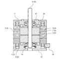
本発明の実施形態に係るハイブリッド型ステッピングモータについて、図を参照して説明する。図1は、ハイブリッド型ステッピングモータ1の構造を示した断面図である。ステータ2は、ステータコア3とステータコア3にインシュレータ4を介して巻回した巻線5から構成されている。ステータコア3は、軟磁性材からなり、四角形の筒状で径内方に延在する複数の極歯を有したコアを複数枚、軸方向に積層して構成され、各極歯にはインシュレータ4を介して巻線5が巻回されている。各極歯の先端には複数の小歯を有している。また、小歯の内側には所定のギャップを介してロータ6が回転可能に配置されている。
<Embodiment>
A hybrid stepping motor according to an embodiment of the present invention will be described with reference to the drawings. FIG. 1 is a cross-sectional view showing the structure of the hybrid stepping motor 1. The
ロータ6は、ロータマグネット7を挟持する2組のロータコア8、9とシャフト10から構成され、2組のロータコア8、9はそれぞれ、軟磁性材からなり、円形で外周に複数の小歯を有したコアを複数枚、軸方向に積層して構成されている。ステータコア3の軸方向両端にはフロントフランジ11とリアフランジ12が配設されており、フロントフランジ11とリアフランジ12は、それぞれステータコア3の内周に嵌合して位置決めされており、フロントフランジ11とリアフランジ12それぞれに装着した軸受13、14にてシャフト10を回転可能に支持している。リアフランジ12の一辺には切欠が形成され、コネクタハウジング15が切欠から径外方に突出している。ステータコア3、フロントフランジ11及びリアフランジ12は貫通孔26にボルト30を挿通して結合されている。
The
フロントフランジ11とリアフランジ12は、金属材、例えば、アルミ合金のダイカストから形成されている。図2は、図1に示す本発明のハイブリッド型ステッピングモータ1におけるフロントフランジ11の斜視図である。フロントフランジ11は有底四角形の筒状で、底部にはロータ6のシャフト10を回転可能に支持するための軸受13を装着する円筒部21が形成され、円筒部21の中心にはシャフト10を挿通するための挿通穴22が形成されている。円筒部21の外周面からは複数の第1のリブ23(図では8本)が放射状に等ピッチ角で形成されている。円筒部21の上面には環状溝24が形成され、円筒部21の内壁21aと外壁21bを連結する8本の第2のリブ25が、第1のリブ23と同じ位置で放射状に形成されている。
The
<変形例>
図3は、本発明のハイブリッド型ステッピングモータにおけるフロントフランジ11の変形例を示す斜視図である。図2との違いは、円筒部21の内壁21aと外壁21bを連結する第2のリブ25が4本である点である。
<Modification>
FIG. 3 is a perspective view showing a modification of the
次に、実施例を用いて説明する。図5は、比較例としてのフロントフランジの斜視図であって、円筒部21の上面には環状溝24が形成されているが、円筒部21の内壁21aと外壁21bを連結するリブは形成されていない。
Next, a description will be given using an example. FIG. 5 is a perspective view of a front flange as a comparative example, and an
図5に示すフロントフランジを用いたハイブリッド型ステッピングモータを2000ppsで駆動した時の騒音を測定した結果、20000Hzの周波数帯域の中で、4000Hz付近に顕著な騒音ピークを見られた。この4000Hz付近に見られる顕著な騒音ピークは回転数によらず、4000Hz付近に出現した。この結果から、図5に示すフロントフランジを用いたハイブリッド型ステッピングモータを振動シミュレーションにて解析した結果、4000Hz付近にシャフト10が振れる固有振動モードがあることがわかった。また、フロントフランジから突出するシャフト10の振れは、リアフランジ12に具備するコネクタハウジング15の延在方向と同一平面において直交する方向に振れることもわかった(図4の矢印方向)。このシャフト10の振れがベアリングを通じてステータに伝わり、大きく振動すると思われる。
As a result of measuring the noise when the hybrid stepping motor using the front flange shown in FIG. 5 was driven at 2000 pps, a remarkable noise peak was observed in the vicinity of 4000 Hz in the frequency band of 20000 Hz. The remarkable noise peak seen in the vicinity of 4000 Hz appeared near 4000 Hz regardless of the rotational speed. From this result, as a result of analyzing the hybrid stepping motor using the front flange shown in FIG. 5 by vibration simulation, it was found that there is a natural vibration mode in which the
表1はシャフトを4000Hzで加振した際のステータの振動低減量を示したものである。図5に示す比較例のフロントフランジを用いたハイブリッド型ステッピングモータにおける周波数応答シミュレーションでの振動値を100としたとき、図2及び図3に示すフロントフランジ11を用いたハイブリッド型ステッピングモータの振動値を相対値で示した。表1において、実施例1及び実施例2は、図2で示した実施形態及び図3で示した変形例にそれぞれ対応する。図2に示すフロントフランジ11は円筒部21の内壁21aと外壁21bを連結する第2のリブ25が等ピッチ角で8本形成されており、図3に示すフロントフランジ11は円筒部21の内壁21aと外壁21bを連結する第2のリブ25が等ピッチ角で4本形成されている。
Table 1 shows the amount of vibration reduction of the stator when the shaft is vibrated at 4000 Hz. When the vibration value in the frequency response simulation in the hybrid stepping motor using the front flange of the comparative example shown in FIG. 5 is 100, the vibration value of the hybrid stepping motor using the
表1の結果から、円筒部21の上面に環状溝24を形成したフランジ構造では、円筒部21の内壁21aと外壁21bを連結するリブ25を形成することによって、リブ25を形成しない場合に比べて振動の低減ができ、円筒部21の内壁21aと外壁21bを連結するリブ25を8本形成した場合、約5%の振動を低減できるハイブリッド型ステッピングモータを提供できる。
From the results shown in Table 1, in the flange structure in which the
なお、円筒部21の内壁21aと外壁21bを連結する第2のリブ25はシャフト10の振れ方向(リアフランジに具備するコネクタハウジングの延在方向と同一平面において直交する方向)に形成している。この方向に少なくとも2本の第2のリブ25を形成することによって、第2のリブ25を有しない構造よりも振動を抑制することができる。
The

本実施形態では、フロントフランジの環状溝に複数のリブを形成した構成であるが、リアフランジにもフロントフランジと同様、環状溝を形成した場合、環状溝に複数のリブを形成することによって振動低減を図ることができる。 In the present embodiment, the plurality of ribs are formed in the annular groove of the front flange. However, when the annular groove is formed in the rear flange as well as the front flange, vibration is generated by forming the plurality of ribs in the annular groove. Reduction can be achieved.
このように、本発明は、具体的な実施形態に限定されるものではなく、種々の変更を行ったものも含まれるものであり、そのことは、当業者にとって特許請求の範囲の記載から明らかである。 As described above, the present invention is not limited to the specific embodiments but includes various modifications, which will be apparent to those skilled in the art from the description of the scope of claims. It is.
1…ハイブリッド型ステッピングモータ
2…ステータ
3…ステータコア
4…インシュレータ
5…巻線
6…ロータ
7…ロータマグネット
8、9…2組のロータコア
10…シャフト
11…フロントフランジ
12…リアフランジ
13、14…軸受
15…コネクタハウジング
円筒部…21
内壁…21a(円筒部21の)
外壁…21b(円筒部21の)
22…挿通穴
23…第1のリブ
24…環状溝
25…第2のリブ
26…貫通孔
30…ボルト
DESCRIPTION OF SYMBOLS 1 ... Hybrid
Outer wall ... 21b (in the cylindrical portion 21)
22 ... insertion hole 23 ...
Claims (3)
ステータと、
前記ステータの内側に回転可能に配置されたロータと、
前記ステータの軸方向両端にそれぞれ配設されたフロントフランジ及びリアフランジと、を備え、
前記フロントフランジが有底四角形の筒状であり、底部に形成され、前記ロータのシャフトを回転可能に支持するための軸受を装着する円筒部と、前記円筒部の上面に形成された環状溝と、前記環状溝に形成され、前記円筒部の内壁と外壁を連結する複数のリブと、を有することを特徴とするハイブリッド型ステッピングモータ。 A hybrid stepping motor,
A stator,
A rotor rotatably disposed inside the stator;
A front flange and a rear flange respectively disposed at both axial ends of the stator,
The front flange is a bottomed quadrangular cylinder, formed at the bottom, a cylindrical portion for mounting a bearing for rotatably supporting the shaft of the rotor, and an annular groove formed at the upper surface of the cylindrical portion, A hybrid stepping motor comprising a plurality of ribs formed in the annular groove and connecting the inner wall and the outer wall of the cylindrical portion.
前記複数のリブが、前記コネクタハウジングの延在方向と同一平面において直交する方向に少なくとも2本形成されていることを特徴とする請求項1に記載のハイブリッド型ステッピングモータ。 The rear flange includes a connector housing protruding outward in diameter,
The hybrid stepping motor according to claim 1, wherein at least two of the plurality of ribs are formed in a direction orthogonal to the extending direction of the connector housing in the same plane.
3. The hybrid stepping motor according to claim 1, wherein the plurality of ribs are formed radially at an equal pitch angle. 8.
Priority Applications (1)
| Application Number | Priority Date | Filing Date | Title |
|---|---|---|---|
| JP2015129013A JP2017017773A (en) | 2015-06-26 | 2015-06-26 | Hybrid type stepping motor |
Applications Claiming Priority (1)
| Application Number | Priority Date | Filing Date | Title |
|---|---|---|---|
| JP2015129013A JP2017017773A (en) | 2015-06-26 | 2015-06-26 | Hybrid type stepping motor |
Publications (1)
| Publication Number | Publication Date |
|---|---|
| JP2017017773A true JP2017017773A (en) | 2017-01-19 |
Family
ID=57829388
Family Applications (1)
| Application Number | Title | Priority Date | Filing Date |
|---|---|---|---|
| JP2015129013A Pending JP2017017773A (en) | 2015-06-26 | 2015-06-26 | Hybrid type stepping motor |
Country Status (1)
| Country | Link |
|---|---|
| JP (1) | JP2017017773A (en) |
Cited By (1)
| Publication number | Priority date | Publication date | Assignee | Title |
|---|---|---|---|---|
| WO2018143138A1 (en) | 2017-02-02 | 2018-08-09 | 日本精工株式会社 | Rolling bearing |
-
2015
- 2015-06-26 JP JP2015129013A patent/JP2017017773A/en active Pending
Cited By (1)
| Publication number | Priority date | Publication date | Assignee | Title |
|---|---|---|---|---|
| WO2018143138A1 (en) | 2017-02-02 | 2018-08-09 | 日本精工株式会社 | Rolling bearing |
Similar Documents
| Publication | Publication Date | Title |
|---|---|---|
| US11183895B2 (en) | Electric motor | |
| JP5862145B2 (en) | Motor and motor manufacturing method | |
| JP6388066B2 (en) | Brushless motor | |
| JP6627082B2 (en) | Electric motor | |
| US10340758B2 (en) | Permanent magnet motor | |
| JP2013090447A (en) | Induction motor and rotor of induction motor | |
| JP2014039461A (en) | Afpm motor | |
| JP2015070663A (en) | Motor | |
| JP2020188611A (en) | Rotor and motor having the same | |
| JP2004248471A (en) | Stator piece and motor stator using the same | |
| JP5449715B2 (en) | motor | |
| JP2006271142A (en) | Rotary machine | |
| JP2017017773A (en) | Hybrid type stepping motor | |
| JP2019013114A (en) | Brushless motor and blower | |
| JP6420488B2 (en) | Permanent magnet type rotary electric motor and compressor using the same | |
| JP2019009860A (en) | Rotor and rotary electric machine | |
| JP2012080697A (en) | Motor | |
| US11404925B2 (en) | Permanent magnet motor | |
| JP6578516B2 (en) | Induction motor | |
| JP2008086122A (en) | Dc motor | |
| WO2018105626A1 (en) | Motor | |
| JPWO2018025988A1 (en) | Stator core and motor | |
| JP2019162005A (en) | Brushless motor, and blower | |
| JP2017184452A (en) | Induction motor | |
| JP6648612B2 (en) | Stator and motor |