EP3553333A1 - Air bearing with surface layer - Google Patents
Air bearing with surface layer Download PDFInfo
- Publication number
- EP3553333A1 EP3553333A1 EP19168182.4A EP19168182A EP3553333A1 EP 3553333 A1 EP3553333 A1 EP 3553333A1 EP 19168182 A EP19168182 A EP 19168182A EP 3553333 A1 EP3553333 A1 EP 3553333A1
- Authority
- EP
- European Patent Office
- Prior art keywords
- coating
- air bearing
- self
- bearing assembly
- foil
- Prior art date
- Legal status (The legal status is an assumption and is not a legal conclusion. Google has not performed a legal analysis and makes no representation as to the accuracy of the status listed.)
- Granted
Links
Images
Classifications
-
- F—MECHANICAL ENGINEERING; LIGHTING; HEATING; WEAPONS; BLASTING
- F16—ENGINEERING ELEMENTS AND UNITS; GENERAL MEASURES FOR PRODUCING AND MAINTAINING EFFECTIVE FUNCTIONING OF MACHINES OR INSTALLATIONS; THERMAL INSULATION IN GENERAL
- F16C—SHAFTS; FLEXIBLE SHAFTS; ELEMENTS OR CRANKSHAFT MECHANISMS; ROTARY BODIES OTHER THAN GEARING ELEMENTS; BEARINGS
- F16C17/00—Sliding-contact bearings for exclusively rotary movement
- F16C17/02—Sliding-contact bearings for exclusively rotary movement for radial load only
- F16C17/024—Sliding-contact bearings for exclusively rotary movement for radial load only with flexible leaves to create hydrodynamic wedge, e.g. radial foil bearings
-
- F—MECHANICAL ENGINEERING; LIGHTING; HEATING; WEAPONS; BLASTING
- F16—ENGINEERING ELEMENTS AND UNITS; GENERAL MEASURES FOR PRODUCING AND MAINTAINING EFFECTIVE FUNCTIONING OF MACHINES OR INSTALLATIONS; THERMAL INSULATION IN GENERAL
- F16C—SHAFTS; FLEXIBLE SHAFTS; ELEMENTS OR CRANKSHAFT MECHANISMS; ROTARY BODIES OTHER THAN GEARING ELEMENTS; BEARINGS
- F16C17/00—Sliding-contact bearings for exclusively rotary movement
- F16C17/04—Sliding-contact bearings for exclusively rotary movement for axial load only
- F16C17/042—Sliding-contact bearings for exclusively rotary movement for axial load only with flexible leaves to create hydrodynamic wedge, e.g. axial foil bearings
-
- F—MECHANICAL ENGINEERING; LIGHTING; HEATING; WEAPONS; BLASTING
- F16—ENGINEERING ELEMENTS AND UNITS; GENERAL MEASURES FOR PRODUCING AND MAINTAINING EFFECTIVE FUNCTIONING OF MACHINES OR INSTALLATIONS; THERMAL INSULATION IN GENERAL
- F16C—SHAFTS; FLEXIBLE SHAFTS; ELEMENTS OR CRANKSHAFT MECHANISMS; ROTARY BODIES OTHER THAN GEARING ELEMENTS; BEARINGS
- F16C33/00—Parts of bearings; Special methods for making bearings or parts thereof
- F16C33/02—Parts of sliding-contact bearings
- F16C33/04—Brasses; Bushes; Linings
- F16C33/06—Sliding surface mainly made of metal
- F16C33/10—Construction relative to lubrication
- F16C33/1095—Construction relative to lubrication with solids as lubricant, e.g. dry coatings, powder
-
- F—MECHANICAL ENGINEERING; LIGHTING; HEATING; WEAPONS; BLASTING
- F16—ENGINEERING ELEMENTS AND UNITS; GENERAL MEASURES FOR PRODUCING AND MAINTAINING EFFECTIVE FUNCTIONING OF MACHINES OR INSTALLATIONS; THERMAL INSULATION IN GENERAL
- F16C—SHAFTS; FLEXIBLE SHAFTS; ELEMENTS OR CRANKSHAFT MECHANISMS; ROTARY BODIES OTHER THAN GEARING ELEMENTS; BEARINGS
- F16C2206/00—Materials with ceramics, cermets, hard carbon or similar non-metallic hard materials as main constituents
- F16C2206/80—Cermets, i.e. composites of ceramics and metal
- F16C2206/82—Cermets, i.e. composites of ceramics and metal based on tungsten carbide [WC]
-
- F—MECHANICAL ENGINEERING; LIGHTING; HEATING; WEAPONS; BLASTING
- F16—ENGINEERING ELEMENTS AND UNITS; GENERAL MEASURES FOR PRODUCING AND MAINTAINING EFFECTIVE FUNCTIONING OF MACHINES OR INSTALLATIONS; THERMAL INSULATION IN GENERAL
- F16C—SHAFTS; FLEXIBLE SHAFTS; ELEMENTS OR CRANKSHAFT MECHANISMS; ROTARY BODIES OTHER THAN GEARING ELEMENTS; BEARINGS
- F16C2223/00—Surface treatments; Hardening; Coating
- F16C2223/30—Coating surfaces
- F16C2223/60—Coating surfaces by vapour deposition, e.g. PVD, CVD
-
- F—MECHANICAL ENGINEERING; LIGHTING; HEATING; WEAPONS; BLASTING
- F16—ENGINEERING ELEMENTS AND UNITS; GENERAL MEASURES FOR PRODUCING AND MAINTAINING EFFECTIVE FUNCTIONING OF MACHINES OR INSTALLATIONS; THERMAL INSULATION IN GENERAL
- F16C—SHAFTS; FLEXIBLE SHAFTS; ELEMENTS OR CRANKSHAFT MECHANISMS; ROTARY BODIES OTHER THAN GEARING ELEMENTS; BEARINGS
- F16C2360/00—Engines or pumps
- F16C2360/23—Gas turbine engines
Definitions
- This disclosure relates generally to air bearings, and more specifically, to air bearings for operation at higher temperatures.
- Air bearing assemblies require airfoils to provide lubrication, lowering torque, to generate an air film for the bearing to operate.
- Current airfoil coatings use polymeric coatings, such as Teflon and particle-filled polyimides, and are limited by their operating temperatures and are expensive to manufacture. Lower temperature thresholds require excess bleed air to operate, lowering efficiency, while the application of the coatings requires extensive labor.
- An example embodiment of an air bearing assembly includes at least a first member and a shaft with a flange configured to rotate with respect to the first member.
- the first stationary member has a coating on at least one surface facing at least one of the shaft and the flange.
- the coating includes tungsten carbide, a nonpolymeric self-lubricating coating, or a combination thereof.
- An example embodiment of a foil bearing for an air bearing assembly includes a plurality of convex foils arranged generally about a rotational axis, the foil bearing having a first side, a second opposing side, and an opening centered therethrough.
- a coating is disposed on the plurality of foils on at least one of the first side and the second side.
- the coating includes tungsten carbide, a nonpolymeric self-lubricating coating, or a combination thereof.
- An example embodiment of a method of making a foil bearing for an air bearing assembly includes arranging a plurality of convex foils generally about a rotational axis to form a foil bearing, the foil bearing having a first side, a second opposing side, and an opening centered therethrough, about the rotational axis.
- a coating is applied which includes tungsten carbide, a nonpolymeric self-lubricating coating, or a combination thereof to at least one of the first side and the second side of the foil bearing.
- the coating is applied by one of plasma spraying, chemical vapor deposition, and physical vapor deposition.
- Vapor deposition of hard, self-lubricating materials can provide the lubricity to create an air film with minimal torque.
- the entire foil bearing could be coated which would prevent wear and lower friction.
- smooth surfaces resulting from CVD/PVD would not need to be post-coat machined, lowering costs substantially.
- Coating materials are self-lubricating, and the lubricious polymeric matrix required for other coatings, such as fluorinated coatings, can be eliminated which leads to lower total manufacturing cost and ability to operate at higher temperatures.
- FIGS. 1A and 1B show an embodiment of air bearing assembly 10, a non-limiting example of which can be installed in a gas turbine engine (not shown).
- Air bearing assembly 10 includes at least a first stationary member, with shaft 14 and flange 16 configured to rotate with respect to at least the first stationary member, which can include, for example, journal 20 or foil bearing(s) 22.
- journal 20 is arranged on shaft 14, and one or more foil bearings 22, which may be spring-loaded, are disposed adjacent flange 16.
- FIGS. 1A and 1B show foil bearings 22 as basic disc shapes with an opening through the center of each, aligned with a rotational axis of the air bearing assembly 10. Additional details of at least one embodiment of foil bearing 22 are shown and described subsequently.
- air bearing unit 18 (specifically shaft 14 and flange 16) is in normal operation, rotating around its design operating speed, rotation relative to stationary elements 20, 22 causes a thin, high-pressure film of air to form therearound, separating air bearing unit 18 from journal 20 and foil bearings 22. This allows air bearing unit 18 to rotate in a near frictionless manner.
- air bearing unit 18 is made of steel.
- Shaft 14 includes opening 24, which is configured to receive a drive or other power shaft (not shown).
- the omitted drive shaft can be connected to a component of a gas turbine engine or air cycle machine (ACM).
- ACM air cycle machine
- one or more stationary members such as journal 20 and/or foil bearings 22, has a coating 34 on one or more respective surface(s) 28, 30, 32 each facing shaft 14 and/or flange 16.
- Coating 34 is a hard coating that can withstand the operational environment of the air bearing assembly 10 (which includes high temperatures and/or pressures) and withstand wear during spin-up or spin-down.
- Coating 34 which may vary in composition and/or thickness among each surface 28, 30, 32, can include tungsten carbide, a nonpolymeric self-lubricating coating, or a combination thereof.
- the coating can withstand an operating temperature above 550° F (about 290° C), and in certain of those embodiments, the coating can withstand an operating temperature above 750° F (about 400° C).
- the coating can range from about 0.00004 inch (1 micron) to 0.002 inch (50 microns) thick.
- a second stationary member can be disposed on a side of flange 16 opposite the first stationary member (journal 20 or foil bearing 22).
- the second stationary member can be a second foil bearing 22 which optionally has coating 34 on surface 32 facing flange 16, the coating comprising tungsten carbide, a nonpolymeric self-lubricating coating, or a combination thereof.
- FIG 4 shows foil bearing 22 formed from a plurality of circumferentially arranged foils 40.
- Foil bearing 22 has first side 42, second opposing side 44, and opening 46 centered therethrough for receiving shaft 14 of air bearing unit 18 (shown in Figures 1A-2 ).
- Coating 34 is disposed on at least one surface including at least first side 42 or second side 44.
- One or more individual foils 40 may be convex to facilitate formation of the air film.
- coating 34 includes tungsten carbide, a nonpolymeric self-lubricating coating, or a combination thereof.
- coating 34 is self-lubricating.
- lubrication facilitates the low-torque rotation of air bearing unit 18 with respect to stationary element(s) such as journal 20 and foil bearings 22 during spin-up and spin-down, prior to the formation of the air film at an intersection thereof
- stationary element(s) such as journal 20 and foil bearings 22
- one or both foil bearings 22 require lubrication at one or more of surfaces including at least first side 42 or second side 44 of foilbearing(s) 22.
- both foil bearings 22 are arranged with a coated surface facing flange 16 (shown in Figures 1A-2 ).
- Self-lubricating coatings eliminate the need for separate lubricants or fluorinated polymer coatings which act as lubricants. Fluorinated polymer coatings in particular cannot withstand high temperatures, limiting suitable operating environments. Therefore, self-lubricating coatings provide not only cost savings and a reduction in manufacturing complexity for foil bearings 22, but also allow foil bearings 22 (and in turn an air bearing assembly) to be used in a wider range of applications.
- the self-lubricating coating is selected from a group consisting of: diamond-like carbon (DLC), WS 2 , WSi 2 , AgO, Ag, BN (amorphous or hexagonal), MoS 2 , and combinations thereof.
- DLC diamond-like carbon
- WCC tungsten carbide carbon
- WC/C tungsten carbide carbon
- Tungsten-DLC plasma assisted physical vapor deposition
- the Tungsten-DLC coating has a thickness of about 5 microns (0.0002 inches) or less.
- BAM boron / aluminum / magnesium
- This coating can be applied by CVD, PVD, or a plasma spray process.
- BAM-based coatings can include dopants such as TiB 2 in some examples, or ceramic dopants in other examples.
- coating 34 is a tungsten-carbide-based coating.
- the tungsten-carbide-based coating is applied by CVD.
- the tungsten-carbide-based coating can withstand temperatures up to about 750° F (about 400° C), and provides a more abrasion- and corrosion-resistant surface than a predominantly chromium-based coating. While free from chromium, however, the tungsten-carbide-based coating is not self-lubricating. Like most suitable coatings 34 described herein, the tungsten-carbide-based coating is free from hexavalent chromium.
- An example embodiment of an air bearing assembly includes at least a first member and a shaft with a flange configured to rotate with respect to the first stationary member.
- the first member has a coating on at least one stationary surface facing at least one of the shaft and the flange.
- the coating includes tungsten carbide, a nonpolymeric self-lubricating coating, or a combination thereof.
- the air bearing assembly of the preceding paragraph can optionally include, additionally and/or alternatively, any one or more of the following features, configurations and/or additional components:
- An air bearing assembly includes a first member; and a shaft with a flange configured to rotate with respect to the first member; wherein the first member has a coating on at least one stationary surface facing at least one of the shaft and the flange, the coating comprising tungsten carbide, a nonpolymeric self-lubricating coating, or a combination thereof.
- a further embodiment of the foregoing air bearing assembly wherein the first member is one of a stationary journal and a stationary foil bearing.
- DLC diamond-like carbon
- a further embodiment of any of the foregoing air bearing assemblies further comprising: a second stationary member disposed on a side of the flange opposite the first stationary member, wherein the second stationary member has a coating on a surface facing the flange, the coating comprising tungsten carbide, a nonpolymeric self-lubricating coating, or a combination thereof.
- An example embodiment of a foil bearing for an air bearing assembly includes a plurality of convex foils arranged generally about a rotational axis, the foil bearing having a first side, a second opposing side, and an opening centered therethrough.
- a coating is disposed on the plurality of foils on at least one of the first side and the second side.
- the coating includes tungsten carbide, a nonpolymeric self-lubricating coating, or a combination thereof.
- the foil bearing of the preceding paragraph can optionally include, additionally and/or alternatively, any one or more of the following features, configurations and/or additional components:
- An foil bearing includes a plurality of convex foils arranged generally about a rotational axis, the foil bearing having a first side, a second opposing side, and an opening centered therethrough; and a coating on at least one surface including at least the first side or the second side, the coating comprising tungsten carbide, a nonpolymeric self-lubricating coating, or a combination thereof.
- a further embodiment of the foregoing foil bearing, wherein the coating can withstand an operating temperature above 550° F (about 288° C).
- DLC diamond-like carbon
- An example embodiment of a method of making a foil bearing for an air bearing assembly includes arranging a plurality of convex foils generally about a rotational axis to form a foil bearing, the foil bearing having a first side, a second opposing side, and an opening centered therethrough, about the rotational axis.
- a coating is applied which includes tungsten carbide, a nonpolymeric self-lubricating coating, or a combination thereof to at least one of the first side and the second side of the foil bearing.
- the coating is applied by one of plasma spraying, chemical vapor deposition, and physical vapor deposition.
- the preceding method can optionally include, additionally and/or alternatively, any one or more of the following features, configurations and/or additional components:
- a method includes arranging a plurality of convex foils generally about a rotational axis to form a foil bearing, the foil bearing having a first side, a second opposing side, and an opening centered therethrough, about the rotational axis; and applying a coating comprising tungsten carbide, a nonpolymeric self-lubricating coating, or a combination thereof to at least one of the first face and the second face by one of plasma spraying, chemical vapor deposition, and physical vapor deposition.
- the self-lubricating coating is selected from a group consisting of: diamond-like carbon (DLC), WS 2 , WSi 2 , AgO, Ag, BN, MoS 2 , and combinations thereof.
- DLC diamond-like carbon
Landscapes
- Engineering & Computer Science (AREA)
- General Engineering & Computer Science (AREA)
- Mechanical Engineering (AREA)
- Physics & Mathematics (AREA)
- Fluid Mechanics (AREA)
- Sliding-Contact Bearings (AREA)
- Support Of The Bearing (AREA)
Abstract
Description
- This disclosure relates generally to air bearings, and more specifically, to air bearings for operation at higher temperatures.
- Air bearing assemblies require airfoils to provide lubrication, lowering torque, to generate an air film for the bearing to operate. Current airfoil coatings use polymeric coatings, such as Teflon and particle-filled polyimides, and are limited by their operating temperatures and are expensive to manufacture. Lower temperature thresholds require excess bleed air to operate, lowering efficiency, while the application of the coatings requires extensive labor.
- An example embodiment of an air bearing assembly includes at least a first member and a shaft with a flange configured to rotate with respect to the first member. The first stationary member has a coating on at least one surface facing at least one of the shaft and the flange. The coating includes tungsten carbide, a nonpolymeric self-lubricating coating, or a combination thereof.
- An example embodiment of a foil bearing for an air bearing assembly includes a plurality of convex foils arranged generally about a rotational axis, the foil bearing having a first side, a second opposing side, and an opening centered therethrough. A coating is disposed on the plurality of foils on at least one of the first side and the second side. The coating includes tungsten carbide, a nonpolymeric self-lubricating coating, or a combination thereof.
- An example embodiment of a method of making a foil bearing for an air bearing assembly includes arranging a plurality of convex foils generally about a rotational axis to form a foil bearing, the foil bearing having a first side, a second opposing side, and an opening centered therethrough, about the rotational axis. A coating is applied which includes tungsten carbide, a nonpolymeric self-lubricating coating, or a combination thereof to at least one of the first side and the second side of the foil bearing. The coating is applied by one of plasma spraying, chemical vapor deposition, and physical vapor deposition.
-
-
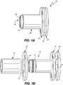
Figure 1A schematically shows an air bearing assembly with a journal and a foil bearing. -
Figure 1B is an exploded view of the example air bearing assembly inFigure 1A . -
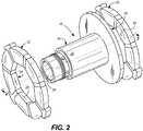
Figure 2 shows an isometric view of the foil bearings interacting in the air bearing assembly ofFigures 1A and 1B . -
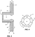
Figure 3 shows an example foil bearing for an air bearing assembly. -
Figure 4 shows a cutaway view of the foil bearing ofFigure 3 . - Vapor deposition of hard, self-lubricating materials can provide the lubricity to create an air film with minimal torque. The entire foil bearing could be coated which would prevent wear and lower friction. In addition, smooth surfaces resulting from CVD/PVD would not need to be post-coat machined, lowering costs substantially. Coating materials are self-lubricating, and the lubricious polymeric matrix required for other coatings, such as fluorinated coatings, can be eliminated which leads to lower total manufacturing cost and ability to operate at higher temperatures.
-
Figures 1A and 1B show an embodiment of air bearingassembly 10, a non-limiting example of which can be installed in a gas turbine engine (not shown).Air bearing assembly 10 includes at least a first stationary member, withshaft 14 andflange 16 configured to rotate with respect to at least the first stationary member, which can include, for example,journal 20 or foil bearing(s) 22. In this example,journal 20 is arranged onshaft 14, and one ormore foil bearings 22, which may be spring-loaded, are disposedadjacent flange 16. For simplicity and clarity only,FIGS. 1A and 1B show foil bearings 22 as basic disc shapes with an opening through the center of each, aligned with a rotational axis of the air bearingassembly 10. Additional details of at least one embodiment of foil bearing 22 are shown and described subsequently. - When air bearing unit 18 (specifically
shaft 14 and flange 16) is in normal operation, rotating around its design operating speed, rotation relative tostationary elements unit 18 fromjournal 20 andfoil bearings 22. This allows air bearingunit 18 to rotate in a near frictionless manner. In some examples,air bearing unit 18 is made of steel. - Shaft 14 includes opening 24, which is configured to receive a drive or other power shaft (not shown). For example, the omitted drive shaft can be connected to a component of a gas turbine engine or air cycle machine (ACM).
- During times when air bearing
unit 18 is not rotating at its intended operating speed, for example during spin-up or spin-down of the engine or ACM,shaft 14 andflange 16 frequently contactjournal 20 and/orfoil bearings 22, and wear can occur on the surfaces in frictional contact. During spin-up,air bearing unit 18 rotates with increasing speed until it reaches the normal operating speed, while during spin-down, the air bearingunit 18 decreases rotational speed from to a lower speed or stationary position. - Thus in
Figure 2 and3 , one or more stationary members, such asjournal 20 and/orfoil bearings 22, has acoating 34 on one or more respective surface(s) 28, 30, 32 each facingshaft 14 and/orflange 16.Coating 34 is a hard coating that can withstand the operational environment of the air bearing assembly 10 (which includes high temperatures and/or pressures) and withstand wear during spin-up or spin-down.Coating 34, which may vary in composition and/or thickness among eachsurface - As referenced in
Figures 1A and 1B , a second stationary member can be disposed on a side offlange 16 opposite the first stationary member (journal 20 or foil bearing 22). The second stationary member can be a second foil bearing 22 which optionally has coating 34 onsurface 32 facingflange 16, the coating comprising tungsten carbide, a nonpolymeric self-lubricating coating, or a combination thereof. -
Figure 4 shows foil bearing 22 formed from a plurality of circumferentially arrangedfoils 40. Foil bearing 22 hasfirst side 42, secondopposing side 44, and opening 46 centered therethrough for receivingshaft 14 of air bearing unit 18 (shown inFigures 1A-2 ). Coating 34 is disposed on at least one surface including at leastfirst side 42 orsecond side 44. One or moreindividual foils 40 may be convex to facilitate formation of the air film. - In certain embodiments,
coating 34 includes tungsten carbide, a nonpolymeric self-lubricating coating, or a combination thereof. In a particular example,coating 34 is self-lubricating. As mentioned regardingFigures 1A and 1B , lubrication facilitates the low-torque rotation of air bearingunit 18 with respect to stationary element(s) such asjournal 20 andfoil bearings 22 during spin-up and spin-down, prior to the formation of the air film at an intersection thereof For instance, one or bothfoil bearings 22 require lubrication at one or more of surfaces including at leastfirst side 42 orsecond side 44 of foilbearing(s) 22. Preferably, bothfoil bearings 22 are arranged with a coated surface facing flange 16 (shown inFigures 1A-2 ). - Self-lubricating coatings eliminate the need for separate lubricants or fluorinated polymer coatings which act as lubricants. Fluorinated polymer coatings in particular cannot withstand high temperatures, limiting suitable operating environments. Therefore, self-lubricating coatings provide not only cost savings and a reduction in manufacturing complexity for
foil bearings 22, but also allow foil bearings 22 (and in turn an air bearing assembly) to be used in a wider range of applications. In a particular example, the self-lubricating coating is selected from a group consisting of: diamond-like carbon (DLC), WS2, WSi2, AgO, Ag, BN (amorphous or hexagonal), MoS2, and combinations thereof. - Other example applications of self-lubricating
coatings 34 are free of hexavalent chrome or other carcinogenic compounds and precursors. One example is a diamond-like carbon ("DLC") coating. One example DLC coating includes silicon oxide and/or silver, and is applied by PVD. Another example DLC coating includes tungsten (tungsten carbide carbon, or WCC, or WC/C, or Tungsten-DLC), and is applied by a type of PVD known as plasma assisted physical vapor deposition (PAPVD). The Tungsten-DLC coating has a thickness of about 5 microns (0.0002 inches) or less. - Another example chromium-free self-lubricating coating is a boron / aluminum / magnesium ("BAM")-based (formally AlMgB14, but sometimes closer to Al0.75Mg0.75B14). This coating can be applied by CVD, PVD, or a plasma spray process. BAM-based coatings can include dopants such as TiB2 in some examples, or ceramic dopants in other examples.
- In another example, coating 34 is a tungsten-carbide-based coating. The tungsten-carbide-based coating is applied by CVD. The tungsten-carbide-based coating can withstand temperatures up to about 750° F (about 400° C), and provides a more abrasion- and corrosion-resistant surface than a predominantly chromium-based coating. While free from chromium, however, the tungsten-carbide-based coating is not self-lubricating. Like most
suitable coatings 34 described herein, the tungsten-carbide-based coating is free from hexavalent chromium. - The following are non-exclusive descriptions of possible embodiments of the present invention.
- An example embodiment of an air bearing assembly includes at least a first member and a shaft with a flange configured to rotate with respect to the first stationary member. The first member has a coating on at least one stationary surface facing at least one of the shaft and the flange. The coating includes tungsten carbide, a nonpolymeric self-lubricating coating, or a combination thereof.
- The air bearing assembly of the preceding paragraph can optionally include, additionally and/or alternatively, any one or more of the following features, configurations and/or additional components:
- An air bearing assembly according to an exemplary embodiment of this disclosure, among other possible things includes a first member; and a shaft with a flange configured to rotate with respect to the first member; wherein the first member has a coating on at least one stationary surface facing at least one of the shaft and the flange, the coating comprising tungsten carbide, a nonpolymeric self-lubricating coating, or a combination thereof.
- A further embodiment of the foregoing air bearing assembly, wherein the first member is one of a stationary journal and a stationary foil bearing.
- A further embodiment of any of the foregoing air bearing assemblies, wherein the coating can withstand an operating temperature above 550° F (about 288° C).
- A further embodiment of any of the foregoing air bearing assemblies, wherein the coating can withstand an operating temperature above 750° F (about 400° C).
- A further embodiment of any of the foregoing air bearing assemblies, wherein the coating is greater than about 0.00004 inch (1 micron) thick.
- A further embodiment of any of the foregoing air bearing assemblies, wherein the coating is less than 0.002 inch (50 microns) thick.
- A further embodiment of any of the foregoing air bearing assemblies, wherein the self-lubricating coating is selected from a group consisting of: diamond-like carbon (DLC), WS2, WSi2, AgO, Ag, BN, MoS2, and combinations thereof.
- A further embodiment of any of the foregoing air bearing assemblies, wherein the coating is free of fluorinated compounds.
- A further embodiment of any of the foregoing air bearing assemblies, further comprising: a second stationary member disposed on a side of the flange opposite the first stationary member, wherein the second stationary member has a coating on a surface facing the flange, the coating comprising tungsten carbide, a nonpolymeric self-lubricating coating, or a combination thereof.
- An example embodiment of a foil bearing for an air bearing assembly includes a plurality of convex foils arranged generally about a rotational axis, the foil bearing having a first side, a second opposing side, and an opening centered therethrough. A coating is disposed on the plurality of foils on at least one of the first side and the second side. The coating includes tungsten carbide, a nonpolymeric self-lubricating coating, or a combination thereof.
- The foil bearing of the preceding paragraph can optionally include, additionally and/or alternatively, any one or more of the following features, configurations and/or additional components:
- An foil bearing according to an exemplary embodiment of this disclosure, among other possible things includes a plurality of convex foils arranged generally about a rotational axis, the foil bearing having a first side, a second opposing side, and an opening centered therethrough; and a coating on at least one surface including at least the first side or the second side, the coating comprising tungsten carbide, a nonpolymeric self-lubricating coating, or a combination thereof.
- A further embodiment of the foregoing foil bearing, wherein the coating can withstand an operating temperature above 550° F (about 288° C).
- A further embodiment of any of the foregoing foil bearings, wherein the coating can withstand an operating temperature above 750° F (about 400° C).
- A further embodiment of any of the foregoing foil bearings, wherein the coating is free of fluorinated compounds.
- A further embodiment of any of the foregoing foil bearings, wherein the self-lubricating coating is selected from a group consisting of: diamond-like carbon (DLC), WS2, WSi2, AgO, Ag, BN, MoS2, and combinations thereof.
- An example embodiment of a method of making a foil bearing for an air bearing assembly includes arranging a plurality of convex foils generally about a rotational axis to form a foil bearing, the foil bearing having a first side, a second opposing side, and an opening centered therethrough, about the rotational axis. A coating is applied which includes tungsten carbide, a nonpolymeric self-lubricating coating, or a combination thereof to at least one of the first side and the second side of the foil bearing. The coating is applied by one of plasma spraying, chemical vapor deposition, and physical vapor deposition.
- The preceding method can optionally include, additionally and/or alternatively, any one or more of the following features, configurations and/or additional components:
- A method according to an exemplary embodiment of this disclosure, among other possible things includes arranging a plurality of convex foils generally about a rotational axis to form a foil bearing, the foil bearing having a first side, a second opposing side, and an opening centered therethrough, about the rotational axis; and applying a coating comprising tungsten carbide, a nonpolymeric self-lubricating coating, or a combination thereof to at least one of the first face and the second face by one of plasma spraying, chemical vapor deposition, and physical vapor deposition.
- A further embodiment of the foregoing method, wherein the self-lubricating coating is selected from a group consisting of: diamond-like carbon (DLC), WS2, WSi2, AgO, Ag, BN, MoS2, and combinations thereof.
- A further embodiment of any of the foregoing methods, wherein the coating is greater than about 0.00004 inch (1 micron) thick and less than 0.002 inch (50 microns) thick.
- A further embodiment of any of the foregoing methods, wherein the coating is free of fluorinated compounds.
- While the invention has been described with reference to an exemplary embodiment(s), it will be understood by those skilled in the art that various changes may be made and equivalents may be substituted for elements thereof without departing from the scope of the invention. In addition, many modifications may be made to adapt a particular situation or material to the teachings of the invention without departing from the essential scope thereof. Therefore, it is intended that the invention not be limited to the particular embodiment(s) disclosed, but that the invention will include all embodiments falling within the scope of the appended claims.
Claims (15)
- An air bearing assembly (10), comprising:a first member; anda shaft (14) with a flange (16) configured to rotate with respect to the first member;wherein the first member has a coating on at least one first surface facing at least one second surface of the shaft (14) and the flange (16), the coating comprising tungsten carbide, a nonpolymeric self-lubricating coating, or a combination thereof.
- The air bearing assembly of claim 1, wherein the first member is one of a stationary journal and a stationary foil bearing.
- The air bearing assembly of claim 1 or 2, wherein the coating can withstand an operating temperature above 550° F (about 288° C), or
wherein the coating can withstand an operating temperature above 750° F (about 400° C). - The air bearing assembly of any preceding claim, wherein the coating is greater than about 0.00004 inch (1 micron) thick, and optionally
wherein the coating is less than 0.002 inch (50 microns) thick. - The air bearing assembly of any preceding claim, wherein the coating is free of fluorinated compounds.
- The air bearing assembly of any preceding claim, wherein the self-lubricating coating is selected from a group consisting of: diamond-like carbon (DLC), WS2, WSi2, AgO, Ag, BN, MoS2, and combinations thereof.
- The air bearing assembly of any preceding claim, further comprising:
a second member disposed on a side of the flange opposite the first stationary member, wherein the second member has a coating on a surface facing the flange, the coating comprising tungsten carbide, a nonpolymeric self-lubricating coating, or a combination thereof. - A foil bearing (22) for an air bearing assembly (10), the foil bearing comprising:a plurality of convex foils (40) arranged generally about a rotational axis, the foil bearing having a first side (42), a second opposing side (44), and an opening (46) centered therethrough; anda coating on at least one surface including at least the first side (42) or the second side (44), the coating comprising tungsten carbide, a nonpolymeric self-lubricating coating, or a combination thereof
- The foil bearing of claim 7, wherein the coating can withstand an operating temperature above 550° F (about 288° C), or
wherein the coating can withstand an operating temperature above 750° F (about 400° C). - The foil bearing of claim 8 or 9, wherein the coating is free of fluorinated compounds.
- The foil bearing of claim 8,9 or 10, wherein the self-lubricating coating is selected from a group consisting of: diamond-like carbon (DLC), WS2, WSi2, AgO, Ag, BN, MoS2, and combinations thereof.
- A method of making a foil bearing (22) for an air bearing assembly (10), comprising:arranging a plurality of convex foils (40) generally about a rotational axis to form a foil bearing, the foil bearing (22) having a first side (42), a second opposing side (44), and an opening (46) centered therethrough, about the rotational axis; andapplying a coating comprising tungsten carbide, a nonpolymeric self-lubricating coating, or a combination thereof to at least one of the first face and the second face by one of plasma spraying, chemical vapor deposition, and physical vapor deposition.
- The method of claim 12, wherein the self-lubricating coating is selected from a group consisting of: diamond-like carbon (DLC), WS2, WSi2, AgO, Ag, BN, MoS2, and combinations thereof.
- The method of claim 12 or 13, wherein the coating is greater than about 0.00004 inch (1 micron) thick and less than 0.002 inch (50 microns) thick.
- The method of claim 12, 13 or 14, wherein the coating is free of fluorinated compounds.
Applications Claiming Priority (1)
| Application Number | Priority Date | Filing Date | Title |
|---|---|---|---|
| US15/952,730 US20190316629A1 (en) | 2018-04-13 | 2018-04-13 | Air bearing with surface layer |
Publications (2)
| Publication Number | Publication Date |
|---|---|
| EP3553333A1 true EP3553333A1 (en) | 2019-10-16 |
| EP3553333B1 EP3553333B1 (en) | 2021-06-02 |
Family
ID=66102977
Family Applications (1)
| Application Number | Title | Priority Date | Filing Date |
|---|---|---|---|
| EP19168182.4A Active EP3553333B1 (en) | 2018-04-13 | 2019-04-09 | Air bearing with surface layer |
Country Status (2)
| Country | Link |
|---|---|
| US (1) | US20190316629A1 (en) |
| EP (1) | EP3553333B1 (en) |
Citations (2)
| Publication number | Priority date | Publication date | Assignee | Title |
|---|---|---|---|---|
| US20070003693A1 (en) * | 2005-07-04 | 2007-01-04 | Yong Bok Lee | Coating material having heat and abrasion resistance and low friction characteristics |
| EP1754860A2 (en) * | 2005-08-19 | 2007-02-21 | General Electric Company | Variable stator vane bushing and washers |
-
2018
- 2018-04-13 US US15/952,730 patent/US20190316629A1/en not_active Abandoned
-
2019
- 2019-04-09 EP EP19168182.4A patent/EP3553333B1/en active Active
Patent Citations (2)
| Publication number | Priority date | Publication date | Assignee | Title |
|---|---|---|---|---|
| US20070003693A1 (en) * | 2005-07-04 | 2007-01-04 | Yong Bok Lee | Coating material having heat and abrasion resistance and low friction characteristics |
| EP1754860A2 (en) * | 2005-08-19 | 2007-02-21 | General Electric Company | Variable stator vane bushing and washers |
Also Published As
| Publication number | Publication date |
|---|---|
| EP3553333B1 (en) | 2021-06-02 |
| US20190316629A1 (en) | 2019-10-17 |
Similar Documents
| Publication | Publication Date | Title |
|---|---|---|
| US5961218A (en) | Water lubricated machine component having contacting sliding surfaces | |
| EP3284980B1 (en) | Sliding part | |
| US8240923B2 (en) | X-ray tube rotating anode assembly bearing | |
| CN102822546B (en) | Rolling bearing | |
| EP1497568A2 (en) | Full complement antifriction bearing | |
| US8011880B2 (en) | Coating for gas bearing | |
| JPH10292867A (en) | Gas seal device | |
| US10533606B2 (en) | Air bearing shaft assembly with surface layer | |
| JP2010190309A (en) | Sliding member | |
| JP2003214444A (en) | Rolling sliding member and rolling device | |
| JP2008169939A (en) | Rolling bearing for vacuum pump and vacuum pump using the same | |
| EP3553333B1 (en) | Air bearing with surface layer | |
| JP7556680B2 (en) | METHOD OF MAKING A SEAL ASSEMBLY FOR A GAS TURBINE ENGINE AND SEAL SEAT - Patent application | |
| CN101424342A (en) | Mechanical sealing member and method for manufacturing same | |
| EP1837418B1 (en) | Slide member having a high-hardness carbon coating | |
| WO2020045455A1 (en) | Double-row self-aligning roller bearing and main shaft support device for wind generation equipped with same | |
| EP3578839B1 (en) | Rolling bearing | |
| JP2003254340A (en) | Bearing device | |
| JP4838455B2 (en) | Rolling sliding member and rolling device | |
| EP3477136B1 (en) | Air bearing | |
| JP2002070870A (en) | Bearing apparatus | |
| JP2013091853A (en) | Sliding member | |
| CN115698512A (en) | Centrifugal pumps for conveying media containing solids | |
| US10927452B2 (en) | Substrate having an intermediate coating and a carbon coating | |
| WO2020067334A1 (en) | Rolling bearing, and main shaft support device for wind power generation |
Legal Events
| Date | Code | Title | Description |
|---|---|---|---|
| PUAI | Public reference made under article 153(3) epc to a published international application that has entered the european phase |
Free format text: ORIGINAL CODE: 0009012 |
|
| STAA | Information on the status of an ep patent application or granted ep patent |
Free format text: STATUS: THE APPLICATION HAS BEEN PUBLISHED |
|
| AK | Designated contracting states |
Kind code of ref document: A1 Designated state(s): AL AT BE BG CH CY CZ DE DK EE ES FI FR GB GR HR HU IE IS IT LI LT LU LV MC MK MT NL NO PL PT RO RS SE SI SK SM TR |
|
| AX | Request for extension of the european patent |
Extension state: BA ME |
|
| STAA | Information on the status of an ep patent application or granted ep patent |
Free format text: STATUS: REQUEST FOR EXAMINATION WAS MADE |
|
| 17P | Request for examination filed |
Effective date: 20191121 |
|
| RBV | Designated contracting states (corrected) |
Designated state(s): AL AT BE BG CH CY CZ DE DK EE ES FI FR GB GR HR HU IE IS IT LI LT LU LV MC MK MT NL NO PL PT RO RS SE SI SK SM TR |
|
| GRAP | Despatch of communication of intention to grant a patent |
Free format text: ORIGINAL CODE: EPIDOSNIGR1 |
|
| STAA | Information on the status of an ep patent application or granted ep patent |
Free format text: STATUS: GRANT OF PATENT IS INTENDED |
|
| INTG | Intention to grant announced |
Effective date: 20201106 |
|
| RIN1 | Information on inventor provided before grant (corrected) |
Inventor name: FISKE, WILLIAM R. Inventor name: SMITH, BLAIR Inventor name: RANKIN, KEVIN M. Inventor name: POTEET, STEVEN |
|
| GRAS | Grant fee paid |
Free format text: ORIGINAL CODE: EPIDOSNIGR3 |
|
| GRAA | (expected) grant |
Free format text: ORIGINAL CODE: 0009210 |
|
| STAA | Information on the status of an ep patent application or granted ep patent |
Free format text: STATUS: THE PATENT HAS BEEN GRANTED |
|
| REG | Reference to a national code |
Ref country code: CH Ref legal event code: EP |
|
| AK | Designated contracting states |
Kind code of ref document: B1 Designated state(s): AL AT BE BG CH CY CZ DE DK EE ES FI FR GB GR HR HU IE IS IT LI LT LU LV MC MK MT NL NO PL PT RO RS SE SI SK SM TR |
|
| REG | Reference to a national code |
Ref country code: GB Ref legal event code: FG4D |
|
| REG | Reference to a national code |
Ref country code: AT Ref legal event code: REF Ref document number: 1398720 Country of ref document: AT Kind code of ref document: T Effective date: 20210615 |
|
| REG | Reference to a national code |
Ref country code: IE Ref legal event code: FG4D |
|
| REG | Reference to a national code |
Ref country code: DE Ref legal event code: R096 Ref document number: 602019004976 Country of ref document: DE |
|
| REG | Reference to a national code |
Ref country code: LT Ref legal event code: MG9D |
|
| PG25 | Lapsed in a contracting state [announced via postgrant information from national office to epo] |
Ref country code: FI Free format text: LAPSE BECAUSE OF FAILURE TO SUBMIT A TRANSLATION OF THE DESCRIPTION OR TO PAY THE FEE WITHIN THE PRESCRIBED TIME-LIMIT Effective date: 20210602 Ref country code: LT Free format text: LAPSE BECAUSE OF FAILURE TO SUBMIT A TRANSLATION OF THE DESCRIPTION OR TO PAY THE FEE WITHIN THE PRESCRIBED TIME-LIMIT Effective date: 20210602 Ref country code: HR Free format text: LAPSE BECAUSE OF FAILURE TO SUBMIT A TRANSLATION OF THE DESCRIPTION OR TO PAY THE FEE WITHIN THE PRESCRIBED TIME-LIMIT Effective date: 20210602 Ref country code: BG Free format text: LAPSE BECAUSE OF FAILURE TO SUBMIT A TRANSLATION OF THE DESCRIPTION OR TO PAY THE FEE WITHIN THE PRESCRIBED TIME-LIMIT Effective date: 20210902 |
|
| REG | Reference to a national code |
Ref country code: NL Ref legal event code: MP Effective date: 20210602 |
|
| REG | Reference to a national code |
Ref country code: AT Ref legal event code: MK05 Ref document number: 1398720 Country of ref document: AT Kind code of ref document: T Effective date: 20210602 |
|
| PG25 | Lapsed in a contracting state [announced via postgrant information from national office to epo] |
Ref country code: GR Free format text: LAPSE BECAUSE OF FAILURE TO SUBMIT A TRANSLATION OF THE DESCRIPTION OR TO PAY THE FEE WITHIN THE PRESCRIBED TIME-LIMIT Effective date: 20210903 Ref country code: RS Free format text: LAPSE BECAUSE OF FAILURE TO SUBMIT A TRANSLATION OF THE DESCRIPTION OR TO PAY THE FEE WITHIN THE PRESCRIBED TIME-LIMIT Effective date: 20210602 Ref country code: SE Free format text: LAPSE BECAUSE OF FAILURE TO SUBMIT A TRANSLATION OF THE DESCRIPTION OR TO PAY THE FEE WITHIN THE PRESCRIBED TIME-LIMIT Effective date: 20210602 Ref country code: PL Free format text: LAPSE BECAUSE OF FAILURE TO SUBMIT A TRANSLATION OF THE DESCRIPTION OR TO PAY THE FEE WITHIN THE PRESCRIBED TIME-LIMIT Effective date: 20210602 Ref country code: LV Free format text: LAPSE BECAUSE OF FAILURE TO SUBMIT A TRANSLATION OF THE DESCRIPTION OR TO PAY THE FEE WITHIN THE PRESCRIBED TIME-LIMIT Effective date: 20210602 Ref country code: NO Free format text: LAPSE BECAUSE OF FAILURE TO SUBMIT A TRANSLATION OF THE DESCRIPTION OR TO PAY THE FEE WITHIN THE PRESCRIBED TIME-LIMIT Effective date: 20210902 |
|
| PG25 | Lapsed in a contracting state [announced via postgrant information from national office to epo] |
Ref country code: EE Free format text: LAPSE BECAUSE OF FAILURE TO SUBMIT A TRANSLATION OF THE DESCRIPTION OR TO PAY THE FEE WITHIN THE PRESCRIBED TIME-LIMIT Effective date: 20210602 Ref country code: ES Free format text: LAPSE BECAUSE OF FAILURE TO SUBMIT A TRANSLATION OF THE DESCRIPTION OR TO PAY THE FEE WITHIN THE PRESCRIBED TIME-LIMIT Effective date: 20210602 Ref country code: SK Free format text: LAPSE BECAUSE OF FAILURE TO SUBMIT A TRANSLATION OF THE DESCRIPTION OR TO PAY THE FEE WITHIN THE PRESCRIBED TIME-LIMIT Effective date: 20210602 Ref country code: SM Free format text: LAPSE BECAUSE OF FAILURE TO SUBMIT A TRANSLATION OF THE DESCRIPTION OR TO PAY THE FEE WITHIN THE PRESCRIBED TIME-LIMIT Effective date: 20210602 Ref country code: NL Free format text: LAPSE BECAUSE OF FAILURE TO SUBMIT A TRANSLATION OF THE DESCRIPTION OR TO PAY THE FEE WITHIN THE PRESCRIBED TIME-LIMIT Effective date: 20210602 Ref country code: PT Free format text: LAPSE BECAUSE OF FAILURE TO SUBMIT A TRANSLATION OF THE DESCRIPTION OR TO PAY THE FEE WITHIN THE PRESCRIBED TIME-LIMIT Effective date: 20211004 Ref country code: RO Free format text: LAPSE BECAUSE OF FAILURE TO SUBMIT A TRANSLATION OF THE DESCRIPTION OR TO PAY THE FEE WITHIN THE PRESCRIBED TIME-LIMIT Effective date: 20210602 Ref country code: CZ Free format text: LAPSE BECAUSE OF FAILURE TO SUBMIT A TRANSLATION OF THE DESCRIPTION OR TO PAY THE FEE WITHIN THE PRESCRIBED TIME-LIMIT Effective date: 20210602 Ref country code: AT Free format text: LAPSE BECAUSE OF FAILURE TO SUBMIT A TRANSLATION OF THE DESCRIPTION OR TO PAY THE FEE WITHIN THE PRESCRIBED TIME-LIMIT Effective date: 20210602 |
|
| REG | Reference to a national code |
Ref country code: DE Ref legal event code: R097 Ref document number: 602019004976 Country of ref document: DE |
|
| PLBE | No opposition filed within time limit |
Free format text: ORIGINAL CODE: 0009261 |
|
| STAA | Information on the status of an ep patent application or granted ep patent |
Free format text: STATUS: NO OPPOSITION FILED WITHIN TIME LIMIT |
|
| PG25 | Lapsed in a contracting state [announced via postgrant information from national office to epo] |
Ref country code: DK Free format text: LAPSE BECAUSE OF FAILURE TO SUBMIT A TRANSLATION OF THE DESCRIPTION OR TO PAY THE FEE WITHIN THE PRESCRIBED TIME-LIMIT Effective date: 20210602 |
|
| 26N | No opposition filed |
Effective date: 20220303 |
|
| PG25 | Lapsed in a contracting state [announced via postgrant information from national office to epo] |
Ref country code: AL Free format text: LAPSE BECAUSE OF FAILURE TO SUBMIT A TRANSLATION OF THE DESCRIPTION OR TO PAY THE FEE WITHIN THE PRESCRIBED TIME-LIMIT Effective date: 20210602 |
|
| PG25 | Lapsed in a contracting state [announced via postgrant information from national office to epo] |
Ref country code: IT Free format text: LAPSE BECAUSE OF FAILURE TO SUBMIT A TRANSLATION OF THE DESCRIPTION OR TO PAY THE FEE WITHIN THE PRESCRIBED TIME-LIMIT Effective date: 20210602 |
|
| REG | Reference to a national code |
Ref country code: CH Ref legal event code: PL |
|
| REG | Reference to a national code |
Ref country code: BE Ref legal event code: MM Effective date: 20220430 |
|
| PG25 | Lapsed in a contracting state [announced via postgrant information from national office to epo] |
Ref country code: MC Free format text: LAPSE BECAUSE OF FAILURE TO SUBMIT A TRANSLATION OF THE DESCRIPTION OR TO PAY THE FEE WITHIN THE PRESCRIBED TIME-LIMIT Effective date: 20210602 Ref country code: LU Free format text: LAPSE BECAUSE OF NON-PAYMENT OF DUE FEES Effective date: 20220409 Ref country code: LI Free format text: LAPSE BECAUSE OF NON-PAYMENT OF DUE FEES Effective date: 20220430 Ref country code: CH Free format text: LAPSE BECAUSE OF NON-PAYMENT OF DUE FEES Effective date: 20220430 |
|
| PG25 | Lapsed in a contracting state [announced via postgrant information from national office to epo] |
Ref country code: BE Free format text: LAPSE BECAUSE OF NON-PAYMENT OF DUE FEES Effective date: 20220430 |
|
| PG25 | Lapsed in a contracting state [announced via postgrant information from national office to epo] |
Ref country code: IE Free format text: LAPSE BECAUSE OF NON-PAYMENT OF DUE FEES Effective date: 20220409 |
|
| P01 | Opt-out of the competence of the unified patent court (upc) registered |
Effective date: 20230522 |
|
| PG25 | Lapsed in a contracting state [announced via postgrant information from national office to epo] |
Ref country code: HU Free format text: LAPSE BECAUSE OF FAILURE TO SUBMIT A TRANSLATION OF THE DESCRIPTION OR TO PAY THE FEE WITHIN THE PRESCRIBED TIME-LIMIT; INVALID AB INITIO Effective date: 20190409 |
|
| PG25 | Lapsed in a contracting state [announced via postgrant information from national office to epo] |
Ref country code: MK Free format text: LAPSE BECAUSE OF FAILURE TO SUBMIT A TRANSLATION OF THE DESCRIPTION OR TO PAY THE FEE WITHIN THE PRESCRIBED TIME-LIMIT Effective date: 20210602 Ref country code: CY Free format text: LAPSE BECAUSE OF FAILURE TO SUBMIT A TRANSLATION OF THE DESCRIPTION OR TO PAY THE FEE WITHIN THE PRESCRIBED TIME-LIMIT Effective date: 20210602 |
|
| PG25 | Lapsed in a contracting state [announced via postgrant information from national office to epo] |
Ref country code: MT Free format text: LAPSE BECAUSE OF FAILURE TO SUBMIT A TRANSLATION OF THE DESCRIPTION OR TO PAY THE FEE WITHIN THE PRESCRIBED TIME-LIMIT Effective date: 20210602 |
|
| PGFP | Annual fee paid to national office [announced via postgrant information from national office to epo] |
Ref country code: FR Payment date: 20250319 Year of fee payment: 7 |
|
| PGFP | Annual fee paid to national office [announced via postgrant information from national office to epo] |
Ref country code: GB Payment date: 20250319 Year of fee payment: 7 |
|
| PGFP | Annual fee paid to national office [announced via postgrant information from national office to epo] |
Ref country code: DE Payment date: 20250319 Year of fee payment: 7 |
|
| PG25 | Lapsed in a contracting state [announced via postgrant information from national office to epo] |
Ref country code: TR Free format text: LAPSE BECAUSE OF FAILURE TO SUBMIT A TRANSLATION OF THE DESCRIPTION OR TO PAY THE FEE WITHIN THE PRESCRIBED TIME-LIMIT Effective date: 20210602 |