EP1754860A2 - Variable stator vane bushing and washers - Google Patents
Variable stator vane bushing and washers Download PDFInfo
- Publication number
- EP1754860A2 EP1754860A2 EP06254338A EP06254338A EP1754860A2 EP 1754860 A2 EP1754860 A2 EP 1754860A2 EP 06254338 A EP06254338 A EP 06254338A EP 06254338 A EP06254338 A EP 06254338A EP 1754860 A2 EP1754860 A2 EP 1754860A2
- Authority
- EP
- European Patent Office
- Prior art keywords
- bushing
- vane
- stator
- assembly
- casing
- Prior art date
- Legal status (The legal status is an assumption and is not a legal conclusion. Google has not performed a legal analysis and makes no representation as to the accuracy of the status listed.)
- Granted
Links
Images


Classifications
-
- F—MECHANICAL ENGINEERING; LIGHTING; HEATING; WEAPONS; BLASTING
- F01—MACHINES OR ENGINES IN GENERAL; ENGINE PLANTS IN GENERAL; STEAM ENGINES
- F01D—NON-POSITIVE DISPLACEMENT MACHINES OR ENGINES, e.g. STEAM TURBINES
- F01D17/00—Regulating or controlling by varying flow
- F01D17/10—Final actuators
- F01D17/12—Final actuators arranged in stator parts
- F01D17/14—Final actuators arranged in stator parts varying effective cross-sectional area of nozzles or guide conduits
- F01D17/16—Final actuators arranged in stator parts varying effective cross-sectional area of nozzles or guide conduits by means of nozzle vanes
- F01D17/162—Final actuators arranged in stator parts varying effective cross-sectional area of nozzles or guide conduits by means of nozzle vanes for axial flow, i.e. the vanes turning around axes which are essentially perpendicular to the rotor centre line
-
- F—MECHANICAL ENGINEERING; LIGHTING; HEATING; WEAPONS; BLASTING
- F04—POSITIVE - DISPLACEMENT MACHINES FOR LIQUIDS; PUMPS FOR LIQUIDS OR ELASTIC FLUIDS
- F04D—NON-POSITIVE-DISPLACEMENT PUMPS
- F04D29/00—Details, component parts, or accessories
- F04D29/05—Shafts or bearings, or assemblies thereof, specially adapted for elastic fluid pumps
- F04D29/056—Bearings
- F04D29/057—Bearings hydrostatic; hydrodynamic
-
- F—MECHANICAL ENGINEERING; LIGHTING; HEATING; WEAPONS; BLASTING
- F04—POSITIVE - DISPLACEMENT MACHINES FOR LIQUIDS; PUMPS FOR LIQUIDS OR ELASTIC FLUIDS
- F04D—NON-POSITIVE-DISPLACEMENT PUMPS
- F04D29/00—Details, component parts, or accessories
- F04D29/40—Casings; Connections of working fluid
- F04D29/52—Casings; Connections of working fluid for axial pumps
- F04D29/54—Fluid-guiding means, e.g. diffusers
- F04D29/56—Fluid-guiding means, e.g. diffusers adjustable
- F04D29/563—Fluid-guiding means, e.g. diffusers adjustable specially adapted for elastic fluid pumps
-
- F—MECHANICAL ENGINEERING; LIGHTING; HEATING; WEAPONS; BLASTING
- F16—ENGINEERING ELEMENTS AND UNITS; GENERAL MEASURES FOR PRODUCING AND MAINTAINING EFFECTIVE FUNCTIONING OF MACHINES OR INSTALLATIONS; THERMAL INSULATION IN GENERAL
- F16C—SHAFTS; FLEXIBLE SHAFTS; ELEMENTS OR CRANKSHAFT MECHANISMS; ROTARY BODIES OTHER THAN GEARING ELEMENTS; BEARINGS
- F16C33/00—Parts of bearings; Special methods for making bearings or parts thereof
- F16C33/02—Parts of sliding-contact bearings
- F16C33/04—Brasses; Bushes; Linings
- F16C33/043—Sliding surface consisting mainly of ceramics, cermets or hard carbon, e.g. diamond like carbon [DLC]
-
- F—MECHANICAL ENGINEERING; LIGHTING; HEATING; WEAPONS; BLASTING
- F05—INDEXING SCHEMES RELATING TO ENGINES OR PUMPS IN VARIOUS SUBCLASSES OF CLASSES F01-F04
- F05D—INDEXING SCHEME FOR ASPECTS RELATING TO NON-POSITIVE-DISPLACEMENT MACHINES OR ENGINES, GAS-TURBINES OR JET-PROPULSION PLANTS
- F05D2230/00—Manufacture
- F05D2230/90—Coating; Surface treatment
-
- F—MECHANICAL ENGINEERING; LIGHTING; HEATING; WEAPONS; BLASTING
- F05—INDEXING SCHEMES RELATING TO ENGINES OR PUMPS IN VARIOUS SUBCLASSES OF CLASSES F01-F04
- F05D—INDEXING SCHEME FOR ASPECTS RELATING TO NON-POSITIVE-DISPLACEMENT MACHINES OR ENGINES, GAS-TURBINES OR JET-PROPULSION PLANTS
- F05D2300/00—Materials; Properties thereof
- F05D2300/20—Oxide or non-oxide ceramics
- F05D2300/21—Oxide ceramics
- F05D2300/2118—Zirconium oxides
-
- F—MECHANICAL ENGINEERING; LIGHTING; HEATING; WEAPONS; BLASTING
- F05—INDEXING SCHEMES RELATING TO ENGINES OR PUMPS IN VARIOUS SUBCLASSES OF CLASSES F01-F04
- F05D—INDEXING SCHEME FOR ASPECTS RELATING TO NON-POSITIVE-DISPLACEMENT MACHINES OR ENGINES, GAS-TURBINES OR JET-PROPULSION PLANTS
- F05D2300/00—Materials; Properties thereof
- F05D2300/20—Oxide or non-oxide ceramics
- F05D2300/22—Non-oxide ceramics
- F05D2300/226—Carbides
- F05D2300/2263—Carbides of tungsten, e.g. WC
-
- F—MECHANICAL ENGINEERING; LIGHTING; HEATING; WEAPONS; BLASTING
- F05—INDEXING SCHEMES RELATING TO ENGINES OR PUMPS IN VARIOUS SUBCLASSES OF CLASSES F01-F04
- F05D—INDEXING SCHEME FOR ASPECTS RELATING TO NON-POSITIVE-DISPLACEMENT MACHINES OR ENGINES, GAS-TURBINES OR JET-PROPULSION PLANTS
- F05D2300/00—Materials; Properties thereof
- F05D2300/20—Oxide or non-oxide ceramics
- F05D2300/22—Non-oxide ceramics
- F05D2300/228—Nitrides
- F05D2300/2283—Nitrides of silicon
-
- F—MECHANICAL ENGINEERING; LIGHTING; HEATING; WEAPONS; BLASTING
- F05—INDEXING SCHEMES RELATING TO ENGINES OR PUMPS IN VARIOUS SUBCLASSES OF CLASSES F01-F04
- F05D—INDEXING SCHEME FOR ASPECTS RELATING TO NON-POSITIVE-DISPLACEMENT MACHINES OR ENGINES, GAS-TURBINES OR JET-PROPULSION PLANTS
- F05D2300/00—Materials; Properties thereof
- F05D2300/50—Intrinsic material properties or characteristics
- F05D2300/501—Elasticity
-
- F—MECHANICAL ENGINEERING; LIGHTING; HEATING; WEAPONS; BLASTING
- F05—INDEXING SCHEMES RELATING TO ENGINES OR PUMPS IN VARIOUS SUBCLASSES OF CLASSES F01-F04
- F05D—INDEXING SCHEME FOR ASPECTS RELATING TO NON-POSITIVE-DISPLACEMENT MACHINES OR ENGINES, GAS-TURBINES OR JET-PROPULSION PLANTS
- F05D2300/00—Materials; Properties thereof
- F05D2300/50—Intrinsic material properties or characteristics
- F05D2300/509—Self lubricating materials; Solid lubricants
-
- F—MECHANICAL ENGINEERING; LIGHTING; HEATING; WEAPONS; BLASTING
- F05—INDEXING SCHEMES RELATING TO ENGINES OR PUMPS IN VARIOUS SUBCLASSES OF CLASSES F01-F04
- F05D—INDEXING SCHEME FOR ASPECTS RELATING TO NON-POSITIVE-DISPLACEMENT MACHINES OR ENGINES, GAS-TURBINES OR JET-PROPULSION PLANTS
- F05D2300/00—Materials; Properties thereof
- F05D2300/60—Properties or characteristics given to material by treatment or manufacturing
- F05D2300/611—Coating
-
- F—MECHANICAL ENGINEERING; LIGHTING; HEATING; WEAPONS; BLASTING
- F05—INDEXING SCHEMES RELATING TO ENGINES OR PUMPS IN VARIOUS SUBCLASSES OF CLASSES F01-F04
- F05D—INDEXING SCHEME FOR ASPECTS RELATING TO NON-POSITIVE-DISPLACEMENT MACHINES OR ENGINES, GAS-TURBINES OR JET-PROPULSION PLANTS
- F05D2300/00—Materials; Properties thereof
- F05D2300/60—Properties or characteristics given to material by treatment or manufacturing
- F05D2300/612—Foam
-
- F—MECHANICAL ENGINEERING; LIGHTING; HEATING; WEAPONS; BLASTING
- F16—ENGINEERING ELEMENTS AND UNITS; GENERAL MEASURES FOR PRODUCING AND MAINTAINING EFFECTIVE FUNCTIONING OF MACHINES OR INSTALLATIONS; THERMAL INSULATION IN GENERAL
- F16C—SHAFTS; FLEXIBLE SHAFTS; ELEMENTS OR CRANKSHAFT MECHANISMS; ROTARY BODIES OTHER THAN GEARING ELEMENTS; BEARINGS
- F16C2360/00—Engines or pumps
- F16C2360/23—Gas turbine engines
-
- Y—GENERAL TAGGING OF NEW TECHNOLOGICAL DEVELOPMENTS; GENERAL TAGGING OF CROSS-SECTIONAL TECHNOLOGIES SPANNING OVER SEVERAL SECTIONS OF THE IPC; TECHNICAL SUBJECTS COVERED BY FORMER USPC CROSS-REFERENCE ART COLLECTIONS [XRACs] AND DIGESTS
- Y02—TECHNOLOGIES OR APPLICATIONS FOR MITIGATION OR ADAPTATION AGAINST CLIMATE CHANGE
- Y02T—CLIMATE CHANGE MITIGATION TECHNOLOGIES RELATED TO TRANSPORTATION
- Y02T50/00—Aeronautics or air transport
- Y02T50/60—Efficient propulsion technologies, e.g. for aircraft
Definitions
- bushings for variable stator vane assemblies are a specially developed composite of carbon fiber reinforcing materials in a polyimide resin matrix manufactured by E. I. DuPont De Nemours and Company of Wilmington, Delaware.
- the bushings are commonly known as VESPEL®CP TM bushings.
- VESPEL® and CP TM are trademarks that are owned by E. I. DuPont De Nemours and Company.
- the polyimide resin used in the VESPEL®CP TM bushings is commonly known as NR150 TM .
- the NR150 TM trademark is owned by Cytec Technology Group of Wilmington, Delaware.
- Yet another advantage of the lubricant coating is that the materials used in the variable stator vane assembly of the present invention, including the antifriction coating, can readily withstand the higher temperatures of operation utilized in current advanced engine designs.
- the materials used in the antifriction coating of the present invention can be utilized at temperatures greater than about 1000°F (538°C), including operational temperatures of up to about 1200°F (649°C), without significant deterioration due to the combined effects of temperature, vibration, and high altitude atmosphere.
- Variable vane assembly 200 further includes a washer 220.
- Washer 220 is substantially flat and includes an outer diameter surface 222 and an inner diameter surface 224. More specifically, washer 220 includes a first wall 226, a second wall 228, and a thickness 230 that is substantially constant from outer diameter surface 222 to inner diameter surface 224. Washer 220 is in direct contact with casing second recessed portion 212 and extends substantially an entire length of casing second recessed portion 212.
- Variable vane assembly 200 is assembled by placing bushing 204 on variable vane 202 such that bushing first portion 216 and bushing second portion 218 contact variable vane 202 and are substantially perpendicular. Variable vane 202 and bushing 204 extend through opening 214 of casing 206.
- the ceramic materials used for these bushings are both strong and stiff in their non-porous form.
- the performance of the seal tubes comprising these materials can be improved by reducing the elastic modulus of the seal tube portion 340 of the bushing. This may be accomplished by including from about 10% to about 35% by volume closed pore porosity, and preferably up to 20% closed pore porosity, in this portion of the bushing.
- closed pore porosity in the seal tube portion 340 of the bushing, the elastic modulus is reduced rendering the seal tube portion 340 more elastic and less stiff, even though the seal tube portion 340 is comprised of the same material as the dense bearing bushing at first end 320 and second end 330.
- the coefficients of friction were measured at various temperatures during the test and an average coefficient (i.e., Avg COF) of friction was calculated as the coefficient of friction for the wear system.
- Table 1 shows the an average coefficient of friction for each example having the average coefficient of friction resulting from tests run at various friction modifier to binder loadings.
- the antifriction coating 370, 470 was formed from drying a composition on the test surface having a binder loading of 10% by weight and friction modifier loadings of from 15% by weight to 25%, corresponding to friction modifier to binder weight ratios of from 1.5:1 to about 2.5:1.
- the balance of the composition is of essentially inert material that is removed during drying.
- Table 1 Ex Binder 10% Friction Modifier COF Initial COF room temp.
Abstract
a plurality of movable metallic stator vanes (350,450);
a metallic stator casing (310,410) supporting the vanes (350,450);
a bushing system positioned between the stator vanes (350,450) and the stator casings (310,410), the bushing system comprising a ceramic bushing, the ceramic bushing selected from the group of ceramic materials consisting of silicon nitride, tungsten carbide and zirconium oxide; and
at least a portion of the ceramic bushing comprising a closed pore porosity and an elastic modulus of less than the elastic modulus of a substantially identical non-porous ceramic material.
Materials and coating systems which produce equal or better wear resistance at reduced materials cost are described. The materials and coating systems fall into four general categories: solid materials from which bushings and washers can be fabricated, coatings bonded to metallic vanes to minimize total system wear, solid lubricant coatings placed on any bushing or vane stem to reduce friction, and porous ceramic material from which seals (340, 440) can be fabricated.
Description
- This invention relates generally to components of gas turbine engines and, in particular, to variable stator vane bushings and washers systems used in the compressor section of the engine.
- In gas turbine engines, for example, aircraft engines, air is drawn into the front of the engine, compressed by a shaft-mounted rotary compressor, and mixed with fuel. The mixture is burned, and the hot exhaust gases are passed through a turbine mounted on a shaft. The flow of gas turns the turbine, which turns the shaft and drives the compressor. The hot exhaust gases flow from the back of the engine, providing thrust that propels the aircraft forward.
- Gas turbine engines generally include a high pressure compressor, a combustor, and a high pressure turbine. The high pressure compressor, combustor, and high pressure turbine are sometimes collectively referred to as a core engine. Such gas turbine engines also may include a low pressure compressor for supplying compressed air, for further compression, to the high pressure compressor, and a fan for supplying air to the low pressure compressor.
- The high pressure compressor typically includes a rotor surrounded by a casing. The casing is typically fabricated to be removable, such as by forming the casing into two halves that are then removably joined together. The high pressure compressor includes a plurality of stages and each stage includes a row of rotor blades and a row of stator vanes. The casing supports the stator vanes, and the rotor supports the rotor blades. The stator vane rows are between the rotor blade rows and direct air flow toward a downstream rotor blade row.
- To improve the overall operation of the compressor, several compressor stator vanes are rotatively mounted to allow each vane to rotate around its longitudinal axis (which extends in a radial direction from the centerline of the engine) to adjust the angular orientation of the vane relative to the airflow through the compressor. These variable stator vane assemblies are utilized to control the amount of air flowing through the compressor to optimize performance of the compressor. Each variable stator vane assembly includes a variable stator vane, which extends between adjacent rotor blades. The orientation of the variable stator vane affects air flow through the compressor. A lever arm is fixedly joined to the vane stem extending outwardly from the vane bushing. The distal end of the lever arm is operatively joined to an actuation ring that controls the orientation of the vane. All of the vane lever arms in a single row may be joined to a common actuation ring for ensuring that all of the variable vanes are simultaneously positioned relative to the airflow in the compressor stage at the same angular orientation.
- A known variable vane assembly includes a variable vane; a trunnion seal, for example, a bushing; and a washer. The variable vane assembly is bolted onto a high pressure compressor stator casing and the bushing and washer surround an opening that extends through the casing. The variable vane includes a vane stem that extends through the opening in the casing and through the bushing and washer. The bushing and washer are referred to herein as a bearing assembly. The bearing assembly produces a low friction surface that prevents metal on metal contact between the vane stem and the casing. Such variable vane assemblies have possible air leakage pathways through the openings in the casing. Also, the high velocity and high temperature air causes oxidation and erosion of the bearing assembly, which may accelerate deterioration of the bearing assembly, lead to failure of the bearing assembly, and eventual failure of the variable vane assembly.
- Once the bearing assembly fails, an increase in leakage through the opening occurs, which results in a performance loss for the compressor. In addition, failure of the bearing assembly may result in contact between the stator vane and the casing, which causes wear and increases overhaul costs of the engine.
- During operation, a gas turbine engine experiences a variety of forces within the engine that affect the bearing structures. For example, during a stall condition, forces on the vane assembly go through a reversal of direction, locally bending the case material that supports the bearing assembly. Such localized bending may result in strain and potential breakage of bearing components, particularly the bushing. High temperature or ceramic bearing materials have an elastic modulus that is much greater than the materials within the vane assembly. The result of the bearing assembly having a much greater elastic modulus is that the bushing and washer are less able to elastically deform with the case, due to the relative stiffness of the bushing/washer material. Therefore, the bushing and washer bearing structures are more susceptible to breakage when exposed to forces, such as the forces experienced during a stall condition.
- A number of structures in the gas turbine engine, including the bushing and washer structures, used with variable stator vanes are subjected to conditions of wear at temperatures ranging from low temperatures to highly elevated temperatures. In addition, the bushing and washers are subject to high altitude atmospheres. In addition to low temperatures, high altitude atmosphere includes little or no water vapor. Water vapor is required for conventional graphite containing lubricants to maintain lubricity.
- One known material for fabrication of bushings for variable stator vane assemblies is a specially developed composite of carbon fiber reinforcing materials in a polyimide resin matrix manufactured by E. I. DuPont De Nemours and Company of Wilmington, Delaware. The bushings are commonly known as VESPEL®CP™ bushings. VESPEL® and CP™ are trademarks that are owned by E. I. DuPont De Nemours and Company. The polyimide resin used in the VESPEL®CP™ bushings is commonly known as NR150™. The NR150™ trademark is owned by Cytec Technology Group of Wilmington, Delaware. Although the VESPEL®CP™ bushings have an extended life at temperatures 450-500°F (232-260°C), the VESPEL®CP™ bushing have an upper temperature limit of 600°F (316°C). Extended operation at temperatures at or above 600°F (316°C) limit their operational life. The polymer matrix bushings do not withstand the combinations of high temperature and vibrational loading experienced in the operation of the gas turbine engine well, leading to a relatively short part life.
- Another known method for reducing wear on the variable stator vane assembly is placing a carbon-containing antifriction coating on a surface in the variable stator vane assembly. This antifriction coating is a coating fabricated from a material that reduces the coefficient of friction between the surface of the trunnion and the surface of the casing. One carbon-containing component known for lubricant coating is graphite. However, graphite has the disadvantage that water vapor is required to maintain lubricity. Atmospheres at aircraft cruise altitudes do not have enough water vapor present for graphite to be lubricious. Graphite also has the disadvantage of poor tribological properties in applications that require reciprocating motion. An additional disadvantage of graphite is that graphite begins to oxidize rapidly at temperatures at or greater than 500°C (932°F). Some variable stator vane systems may experience temperatures in excess of 500°C (932°F). Therefore, a replacement material for graphite in antifriction coating is needed.
- Attempts have also been made to coat the stator vane trunnion with a wear coating. The wear coating attempts to incorporate the low coefficient of friction materials known in the art with hard, smooth wear resistant coating materials into a coating on the vane trunnion. However, the wear coating alone lacks the ability to maintain the properties of each of the individual components (i.e., fails to maintain both low coefficient of friction and wear resistance). In other words, the single wear coating does not provide all of the desired tribological properties (e.g., reduced wear and low coefficient of friction) required for extended operation of variable stator vanes subject to conditions of high temperature, vibration and high altitude atmospheres.
- Accordingly, it would be desirable to provide bearing assemblies fabricated from materials having performance characteristics that will reduce or eliminate air leakage between the stator vane stem and the compressor casing while providing an increase in the durability of the bushing and washer to increase part life in high temperature and vibration loading applications. The present invention fulfills this need, and further provides related advantages.
- Materials, heretofore unknown for use in bearing assemblies, which produce equal or better wear resistance at reduced materials cost have been identified. These alternatives fall into three general categories: (1) solid materials from which bushings and washers can be fabricated, (2) coatings bonded to metallic vanes to minimize total system wear, and (3) solid lubricant coatings placed on any bushing, washer and/or vane trunnion to reduce friction. A large number of combinations therefore exist that can provide solutions to specific mechanical designs. Each design is subjected to different temperature limitations, stresses and cyclic vibrations. Thus a solution for one system may not be an effective solution for a different mechanical system. In addition, the solution must be cost effective for the mechanical system into which it is installed. The present invention provides an effective and cost effective replacement for carbon fiber/polymer matrix bushing systems currently used in existing engine systems and engine systems being developed. The bushing systems of the present invention replace existing bushing systems that are used between vanes made from A286 material, a stainless steel or titanium alloy 6-4 and casings made from M152 material, a steel.
- The present invention utilizes a ceramic bushing comprising either silicon nitride (Si3N4), tungsten carbide (WC), or zirconium oxide (ZrO2). In another embodiment, the bushing may comprise metallic alloys, such as STELLITE® 6, M152, 17-4 PH, or 410 stainless steel. These bushings are strong but relatively inflexible. The vane trunnion may be coated with a tungsten carbide coating or a modified tungsten carbide. Modified tungsten carbide is a tungsten carbide with a small amount of cobalt (WC-Co) sufficient to impart wear resistance, typically about 6-20% by weight Co and preferably about 12% by weight Co. Alternatively, the trunnion may be coated with a plasma vapor deposited (PVD) titanium nitride or tungsten carbide. An antifriction coating may be applied between the tungsten carbide coated vane and the bushing.
- One advantage of an embodiment of the present invention is that the bearing assembly materials significantly improve the service life of the stator vane assembly and reduce air leakage through the opening in the stator casing.
- Yet another advantage of an embodiment of the present invention is that the materials used in the improved seal tube of the bushing assembly have a reduced elastic modulus as compared to the identical non-porous material and compared to the surrounding metallic material. The reduced elastic modulus provides additional flexibility and increases the ability of the bushing to withstand flexing of the surrounding casing and vane structure without breakage.
- Yet another advantage of an embodiment of the present invention is that the materials used in the improved bushing assembly includes porous material having a reduced density resulting in a desirable reduction in weight within the gas turbine engine.
- Yet another advantage of the lubricant coating, according to an embodiment of the present invention, is that the wear coating and antifriction coating combination reduces wear and maintains desirable tribological properties in high altitude atmospheres having little or no water vapor.
- Yet another advantage of the lubricant coating, according to an embodiment of the present invention, is that the variable stator vane assembly provides an efficiency improvement in the turbine engine while reducing overhaul costs caused by wear resulting from metal on metal contact between the stator casing surface and the stator vane surface.
- Yet another advantage of the lubricant coating, according to an embodiment of the present invention, is that the materials used in the variable stator vane assembly of the present invention, including the antifriction coating, can readily withstand the higher temperatures of operation utilized in current advanced engine designs. The materials used in the antifriction coating of the present invention can be utilized at temperatures greater than about 1000°F (538°C), including operational temperatures of up to about 1200°F (649°C), without significant deterioration due to the combined effects of temperature, vibration, and high altitude atmosphere.
- Yet another advantage of the lubricant coating of an embodiment of the present invention is that the antifriction coating is capable of maintaining lubricity in applications that rub in a reciprocating motion.
- Another advantage of the lubricant coating, according to an embodiment of the present invention, is that the antifriction coating is resilient and regenerates in areas where the antifriction coating is rubbed thin or cleaned off the wear surface.
- Yet another advantage of an embodiment of the present invention is that the method provides an inexpensive fabrication method that provides a seal tube at near-net shape, requiring few or no subsequent processing steps prior to installation into the bearing system.
- The invention will now be described in greater detail, by way of example, with reference to the drawings, in which:-
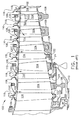
- FIG. 1 is a schematic view of a portion of a prior art high pressure compressor for a turbine engine; and
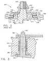
- FIG. 2 is a cross-sectional view of a prior art variable vane assembly used in an aircraft turbine engine high pressure compressor.
- FIG. 3 is a cross sectional view of a bushing assembly of the present invention used in a variable vane assembly of the present invention.
- FIG. 4 is a cross sectional view of a bushing assembly according to an alternate embodiment of the present invention used in a variable vane assembly of the present invention.
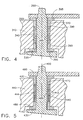
- FIG. 5 is a cross sectional view of a bushing assembly of the present invention used in a variable vane assembly of the present invention depicting a seal tube portion having an H-profile.
- FIG. 6 is a cross sectional view of a bushing assembly according to an alternate embodiment of the present invention used in a variable vane assembly of the present invention depicting a seal tube portion having an H-profile.
- FIG. 7 illustrates a method according to an embodiment of the present invention.
- FIG. 1 is a schematic view of a section of a known high-
pressure compressor 100 for a turbine engine (not shown).Compressor 100 includes a plurality ofstages 102, and eachstage 102 includes a row ofrotor blades 104 and a row of variablestator vane assemblies 106.Rotor blades 104 are typically supported byrotor disks 108, and are connected to arotor shaft 110.Rotor shaft 110 is a high-pressure shaft that is also connected to a high-pressure turbine (not shown).Rotor shaft 110 is surrounded by astator casing 112 that supports variablestator vane assemblies 106. - Each variable
stator vane assembly 106 includes avariable vane 114 and avane stem 116.Vane stem 116 protrudes through anopening 118 incasing 112.Variable vane assemblies 106 further include alever arm 120 extending fromvariable vane 114 that is utilized to rotatevariable vanes 114. The orientation ofvariable vanes 114 relative to the flow path throughcompressor 100 control airflow therethrough. Somevariable vane assemblies 106 are secured toshroud 124 bybolts 122. -
Variable vane assemblies 106 control airflow throughcompressor 100. However,variable vane assemblies 106 also provide a potential pathway for airflow to exitcompressor 100, such as throughopenings 118. Airflow throughopenings 118 reduces the efficiency ofcompressor 100. - FIG. 2 is a cross-sectional view of a known
variable vane assembly 200.Variable vane assembly 200 includes avariable vane 202. Abushing 204 is positioned onvariable vane 202. Acasing 206 supportsvariable vane 202 and includes a first recessedportion 208, aninner portion 210, and a second recessedportion 212. An opening 214 is formed byinner portion 210. -
Bushing 204 includes afirst portion 216 and asecond portion 218. Bushingfirst portion 216 is in direct contact with casing first recessedportion 208 and separatesvariable vane 202 fromcasing 206. Bushingsecond portion 218 contacts casinginner portion 210 and separatesvariable vane 202 fromcasing 206. Bushingfirst portion 216 extends substantially an entire length of casing first recessedportion 208. In addition, bushingsecond portion 218 extends substantially an entire length of casinginner portion 210 and is substantially perpendicular to bushingfirst portion 216.Bushing 204 preventsvariable vane 202 from directly contactingcasing 206. -
Variable vane assembly 200 further includes awasher 220.Washer 220 is substantially flat and includes anouter diameter surface 222 and aninner diameter surface 224. More specifically,washer 220 includes afirst wall 226, asecond wall 228, and athickness 230 that is substantially constant fromouter diameter surface 222 toinner diameter surface 224.Washer 220 is in direct contact with casing second recessedportion 212 and extends substantially an entire length of casing second recessedportion 212. -
Variable vane assembly 200 includes aspacer 232 in contact withwasher 220.Washer 220 prevents contact betweenspacer 232 and casing second recessedportion 212.Spacer 232 includes a spacerfirst portion 234 and a spacersecond portion 236. Spacerfirst portion 234contacts washer 220 and has a length substantially equal to a radial length ofwasher 220.Spacer 232 is separated from bushing 204 bywasher 220. Bushing 204 andwasher 220 do not contact each other.Washer 220 prevents spacer 232 from contactingcasing 206. -
Variable vane 202 also includes a vanefirst portion 238, aledge 240 having a ledgeouter portion 242, and a spacer-seating portion 244.Ledge 240 surrounds avane stem 246. Vane stem 246 (corresponding to FIG. 1, 116) andledge 240 extend through opening 214 (corresponding to FIG. 1, 118) in casing 206 (corresponding to FIG. 1, 112). Bushingsecond portion 218 extends along casinginner portion 210 ofcasing 206. Bushingsecond portion 218 prevents ledgeouter portion 242 from contacting casinginner portion 210. -
Variable vane assembly 200 also includes alever arm 248 positioned aroundvane stem 246 and contactingspacer 232.Lever arm 248 is utilized to adjust the angle ofvariable vane 202, and thus alter the flow of air through the compressor. - In addition,
variable vane assembly 200 includes asleeve 250 contactinglever arm 248, and alever arm nut 252 contactingsleeve 250.Lever arm nut 252 cooperates withvane stem 246 and maintainsvariable vane assembly 200 in contact withcasing 206. -
Variable vane assembly 200 is assembled by placingbushing 204 onvariable vane 202 such that bushingfirst portion 216 and bushingsecond portion 218 contactvariable vane 202 and are substantially perpendicular.Variable vane 202 andbushing 204 extend through opening 214 ofcasing 206. -
Washer 220 is placed oncasing 206adjacent bushing 204.Spacer 232 is positioned onvariable vane 202 andcontacts washer 220.Lever arm 248 is positioned overvane stem 246 and contacts spacer 232.Sleeve 250 is positioned overvane stem 246 andcontacts lever arm 248. Finally,lever arm nut 252 is positioned overvane stem 246 andcontacts sleeve 250. -
Washer 220 andbushing 204 form a bearing assembly used invariable vane assembly 200 and may be used, for example, in a high-pressure compressor.Washer 220 andbushing 204 may be utilized in other environments such as a rotor vane assembly, a low-pressure compressor variable vane assembly, a high-pressure turbine, an intermediate-pressure turbine or a low-pressure turbine. - Materials, heretofore unknown for use in bearing assemblies, which produce equal or better wear resistance at reduced materials cost have been identified. These alternatives fall into four general categories: (1) solid materials from which bushings and washers can be fabricated, (2) coatings bonded to metallic vanes to minimize total system wear, (3) solid lubricant coatings placed on any bushing and/or the vane stem or bushing fitted over the vane stem to reduce friction, and (4) porous seal tube materials that are wear resistant, capable of high temperature service and have a reduced elastic modulus.
- Ideally, the solid bushing should be durable with good wear characteristics, however, the bushing should wear before the case and vane stem (either coated or uncoated) because the bushing is the least expensive and most easily replaced component. The bushings and washers are fabricated by a process according to an embodiment of the present invention that includes an injection molding process or forming a predetermined shape under pressure, then sintering at high temperature to burn away organic binder and fuse the ceramic particles.
- Suitable solid materials for the bushing include injection molded silicon-nitride such as Si3N4, tungsten carbide, and injection molded zirconia. Other suitable materials include, but are not limited to, metallic alloys, such as STELLITE® 6, M152, 17-4 PH, or 410 stainless steel. STELLITE® is a federally registered trademark owned by Deloro Stellite Holdings Corporation of St. Louis, Missouri. The composition of STELLITE® 6 is well-known in the art and is a designation for a cobalt-based alloy comprising about 28 weight percent chromium, about 4.5 weight percent tungsten, about 1.2 weight percent carbon, about 1.1 weight percent silicon, about 1.0 weight percent manganese, a maximum of about 3 weight percent nickel, a maximum of about 3 weight percent iron and the balance cobalt. The composition of M152 is well-known in the art and is a designation for a stainless steel comprising about 12 weight percent chromium, about 2.5 weight percent nickel, about 1.8 weight percent molybdenum, about 0.1 weight percent carbon, about 0.3 weight percent vanadium and balance iron. The composition of 17-4 PH is well-known in the art and is a designation for a stainless steel comprising about 16.5 weight percent chromium, about 4 weight percent nickel, about 3.5 weight percent copper, about 0.3 weight percent niobium, about 0.03 weight percent carbon and balance iron. The composition of 410 stainless steel is well-known in the art and is a designation for a stainless steel comprising about 12 weight percent chromium, about 1.0 weight percent manganese, 1.0 weight percent silicon, about 0.15 weight percent carbon, about 0.04 weight percent phosphorous, about 0.03 weight percent sulfur and balance iron. The present invention may utilize either a Si3N4, tungsten carbide, ZrO2, STELLITE® 6, M152, 17-4 PH, or 410 stainless steel for the bushing. These bushing materials provide improved wear and higher temperature capability than existing Vespel bushings.
- The bushing assembly can assume several configurations. The least expensive alternative utilizes plain bushings with washers as described above instead of flanged bushings. This minimizes possible tensile forces that could cause failure of the ceramic. Two alternative configurations of the spacer bushing that separate the bearing bushing are envisioned. Both of these spacer bushing designs increase the flexibility of the spacer so it may act with the flexibility of a seal.
- Referring to FIG. 3, which depicts a bushing configuration of the present invention, a bushing assembly is comprised of a
first end 320, asecond end 330 and aseal tube portion 340 intermediate to thefirst end 320 and thesecond end 330. Thefirst end 320 andsecond end 330 shown in FIG. 3 includesflanged sections 380, which are comprised of ceramic or metallic material. Thestainless steel vane 350 extends through the bushing assembly disposed withincasing 310. The ceramic materials for use in the bushing assembly may include silicon nitride, tungsten carbide, or zirconia. Alternatively, the material for the bushing assembly may include metallic alloys, such as STELLITE® 6, M152, 17-4 PH, or 410 stainless steel. The ceramic materials used for these bushings are both strong and stiff in their non-porous form. However, the performance of the seal tubes comprising these materials can be improved by reducing the elastic modulus of theseal tube portion 340 of the bushing. This may be accomplished by including from about 10% to about 35% by volume closed pore porosity, and preferably up to 20% closed pore porosity, in this portion of the bushing. By including closed pore porosity in theseal tube portion 340 of the bushing, the elastic modulus is reduced rendering theseal tube portion 340 more elastic and less stiff, even though theseal tube portion 340 is comprised of the same material as the dense bearing bushing atfirst end 320 andsecond end 330. The porous ceramic material of theseal tube portion 340 of the bushing has an elastic modulus that is less than the elastic modulus of eitherfirst end 320 andsecond end 330. The elastic modulus is preferably from about 20% to about 50% less than the elastic modulus of a part comprising a non-porous ceramic material of the same composition. More preferably the elastic modulus is about 50% less than the elastic modulus of a part comprising a non-porous ceramic material of the same composition when there is 20% closed pore porosity. In particular, the porous ceramic material has an elastic modulus that is from about 20% to about 50% less than a non-porous ceramic material having substantially identical composition. The advantage of having a lower elastic modulus in theseal tube portion 340 of the bushing assembly is that interface forces that normally are present in a bushing with a uniform elastic modulus are transmitted to eitherfirst end 320 orsecond end 330. This reduces interface forces and wear in the critical seal area and further extends the life of the bushing assembly. - Referring now to FIG. 4, there is depicted another embodiment of the bushing assembly. FIG. 4 includes the structure shown in FIG. 3. However, instead of the
flanged section 380, FIG. 4 shows thefirst end 320 and thesecond end 330 having astraight section 390 with an intermediateseal tube portion 340. In addition, FIG. 4further shows washers 395 as a part of thefirst end 320 and thesecond end 330.Washer 395 at thefirst end 320 is disposed between thecasing 310 and the lever assembly extending from thevane 350.Washer 395 at thesecond end 330 is disposed between thecasing 310 and thevane 350. - Referring now to FIG. 5, there is depicted another embodiment of a bushing assembly. Like the bushing assembly depicted in FIGS. 3 and 4, the bushing assembly may be a silicon nitride, tungsten carbide, or a zirconium oxide material. Alternatively, the bushing assembly may be fabricated from a metallic material, such as STELLITE® 6, M152, 17-4 PH, or 410 stainless steel. A stainless steel vane stem 450 extends through the bushing assembly disposed within
casing 410. The bushing assembly includes afirst end 420 and asecond end 430.First end 420 andsecond end 430 may beflanged section 480 as shown. The bushing assembly also includes aseal tube portion 440 that has an improved elastic flexibility. However, the improved flexibility is achieved by an H-profile, which includes twocircumferential voids 442 separated by a connectingsegment 444. This arrangement in cross-section such as given in FIG. 5, appears as an H and hence is referred to as a H-profile. Theseal tube portion 440 is made from the same material as thefirst end 420 andsecond end 430. Theseal tube portion 440 is modified to provide improved flexibility. As should be clear, the H-profile in theseal tube portion 440 results in this section of the bushing being more flexible. As a result, interface forces in this area as a result of contact between the bushing assembly andvane 450 are transmitted tofirst end 420 andsecond end 430, both of which are dense and stiff. This extends bushing life in theseal tube portion 440 while minimizing frictional forces in theseal tube portion 440. Of course, the flexibility of an H-profileseal tube portion 440 made with 20% closed-pore porosity would be even more flexible. - Referring now to FIG. 6, there is depicted another embodiment of the bushing assembly. FIG. 6 includes the structure shown in FIG. 5. However, instead of
flanged section 480, FIG. 6 shows thefirst end 420 and thesecond end 430 having astraight section 490 with an intermediateseal tube portion 440. In addition, FIG. 6shows washers 495 as a part of thefirst end 420 and thesecond end 430.Washer 495 at thefirst end 420 is disposed between thecasing 410 and the lever assembly extending fromvane 450.Washer 495 at thesecond end 430 is disposed between the casing and thevane 450. - FIG 7 illustrates a method according to an embodiment of the present invention. As shown in FIG. 7, in
step 501, a powdered ceramic material, such as Si3N4, tungsten carbide or ZrO2, is powder milled for a time up to about 48 hours. Additives, such as sintering agents or forming agents may be added to the powdered ceramic material. The powder milling optionally takes place in order to reduce agglomerations and decrease particle size in order to improve the mixing between powders. Instep 503, the ceramic powder mixture is then formed into a slurry by addition of solvents and/or polymer binder material in order to form a slurry comprising from about 40% to about 60% solid by weight. The formed slurry fromstep 503 is then mixed for about 24 hours to about 2 weeks instep 505. - Upon completion of the
slurry mixing step 505, a pore forming agent is added to the slurry instep 507. The pore forming agent ofstep 507 may be any material capable of forming pores in a sintered ceramic material. In particular, the pore forming agent is a material capable of forming pores within the formed green (i.e., unsintered) part that result in pores within the sintered ceramic material once the sintering step takes place. Suitable pore forming agents include, but are not limited to hollow or solid polymer spheres, glass spheres, ceramic spheres, particles of organic material or blowing agents. Blowing agents are any materials that decompose to release gas and form pores within the ceramic material. The pore forming agents are mixed into the slurry for from about 2 minutes to about 48 hours. - After the pore forming mixing
step 507, the green shape is formed instep 509. A green shape is formed from a slurry that has not been sintered and may be formed and/or shaped into a desired geometry. The forming and/or shaping may take place using any known forming and/or shaping process, including, but not limited to, injection molding, casting or otherwise forming under pressure. The formingstep 509 may also include additional steps such as addition of initiators, addition of sintering agents or other additives, and degassing the slurry. - After forming
step 509 takes place, the formed green shape is then sintered. Sintering takes place by first removing the binder. The binder removal step takes place by heating to 600°C and soaking for from about 0.1 hours to about 3 hours. Heating to the binder removal temperature may take place at any suitable rate. Suitable heating rates to the binder removal temperature include from about 30°C to about 50°C/hour. The binder removal step may result in some additional porosity resulting from the decomposition of the binder and/or solvent within the green shape. After the binder has been sufficiently removed, the part is heated to a temperature of about 1650°C to about 1850°C for times of about 0.5 hours to about 1.5 hour. Suitable heating rates to the sintering temperature include from about 20°C to about 50°C/hour. The sintered ceramic material results in a porous, sintered product having a near-net shape. A product having a near-net shape is a finished product having a reduced or eliminated amount of machining prior to installation, such as installation into a gas turbine engine. In an embodiment of the present invention wherein the bushing comprises a cylindrical seal tube of the porous ceramic material, the excess material present and requiring machining (e.g., excess material present on the inside diameter and/or outside diameter of the seal tube) is preferably less than about 0.025 inches. More preferably, the excess material present and requiring machining is less than about 0.020 inches. Still more preferably, the excess material present and requiring machining is less than about 0.010 inches. - In the present invention, to further reduce the wear and friction forces between the vane, 350 and 450 in FIGS. 3-4 and 5-6, respectively and the ceramic bushing assemblies, the
vane Co coating coatings wear coatings wear coatings coatings antifriction coating vane wear coating trunnion wear coating thin wear coating coatings resultant wear coating - The present invention also utilizes a solid, but soft,
antifriction coating coated vane trunnion antifriction coating location antifriction coating vane 450. Theantifriction coating 370 is preferably coated on a surface of thewear coating bushings tube portion washers - The
antifriction coating antifriction coating antifriction coating coating antifriction coating antifriction coating antifriction coating antifriction coating antifriction coating - The binder material for use in the
antifriction coating antifriction coating 370 maintains tribological properties (e.g., lubricity and wear resistance) of theantifriction coating - The friction modifier is any material that, when added to the binder, produces a friction coefficient suitable for rotating a stator vane in a variable stator vane assembly, capable of maintaining desirable tribological properties at high altitude atmospheres and and/or high temperatures. The high altitude atmospheres include atmospheres to which aircraft are exposed during flight. The high altitude atmosphere includes atmospheres having reduced water vapor. High temperature exposure is a result of the operation of the gas turbine engine. The compression of the gas and the combustion of the fuel result in high temperatures in gas turbine engines. Parts within the gas turbine engine are subject to high temperatures. The coating system of the present invention may find uses in parts within the gas turbine engine that are exposed to temperatures up to about 1200°F. Desirable tribological properties include, but are not limited to low coefficient of friction between sliding surfaces (i.e., high lubricity) and low wear between sliding surfaces. Suitable friction modifier materials include, but are not limited to, tungsten sulfide (e.g., WS2), bismuth telluride (e.g., Bi2Te3), copper sulfide (e.g., Cu2S), bismuth oxide (e.g., Bi2O3) and combinations thereof. Of the friction modifiers, tungsten sulfide (e.g., WS2), bismuth telluride (e.g., Bi2Te3) and bismuth oxide (e.g., Bi2O3) are preferred.
- Table 1 shows examples of antifriction coating materials according to the present invention. These examples do not limit the invention to the combinations of binders and friction modifiers shown therein. Examples 1-5, shown in Table 1, include coefficient of friction (COF) results for particular friction modifier and binder combinations. In order to determine the coefficient of friction, the antifriction coating materials are subject to a sliding wear test as known in the art. The tests were conducted with a reciprocating stroke length of 0.060 inches. Antifriction coating material (i.e., inert material, binder and friction modifier) were loaded onto the wear surfaces and dried to form an
antifriction coating antifriction coating Table 1 Ex Binder 10% Friction Modifier COF Initial COF room temp. COF at 400 °F COF at 750 °F Avg COF 1 titanium oxide tungsten sulfide 0.2 0.5 0.4 0.6 0.43 2 titanium oxide bismuth telluride 0.3 0.7 0.7 0.6 0.58 3 titanium oxide bismuth oxide 0.2 0.7 0.7 0.6 0.55 4 titanium oxide copper sulfide 0.3 0.6 0.7 0.6 0.55 5 aluminum phosphate tungsten sulfide 0.3 0.4 0.5 0.5 0.43 - The friction modifier is preferably incorporated into antifriction coating in a quantity of about 10% to about 500% by weight of binder. More preferably, the friction modifier is incorporated into the antifriction coating from 100% to about 350% by weight of binder. The friction modifier is incorporated into the binder material and is preferably encapsulated in the binder material.
- Encapsulation may take place using any suitable encapsulation method, including but not limited to powder metallurgical encapsulation methods. The
antifriction coating antifriction coating antifriction coating antifriction coating antifriction coating Table 2 Ex. Binder (10 % Loading) Friction Modifier Friction Modifier Loading (%) Friction Modifier to Binder Weight Ratio Avg COF Average Wear (inches) Average Sliding Cycles 6 titanium oxide tungsten sulfide 25 2.5:1 0.47 0.001-0005 575,000 7 titanium oxide tungsten sulfide 30 3:0:1 0.59 0.001-0.005 600,000 8 titanium oxide tungsten sulfide 35 3.5:1 0.40 0.001-0.005 625,000 9 titanium oxide bismuth telluride 25 2.5:1 0.59 0.001-0.004 350,000 10 titanium oxide bismuth telluride 30 3.0:1 0.54 0.001-0.004 362,500 11 titanium oxide bismuth telluride 35 3.5:1 0.55 0.001-0.004 312,500 - Although the average shown in Table 2 range from 350,000 to 635,000 cycles, in each of Examples 6-11, 1,000,000 sliding cycles were made at 750°F (399 °C).
- The variable stator vane assembly of the present invention having the
wear coating antifriction coating 370; 470 and the bushing system opposed surface combination preferably also is resistant to wear over the entire operating temperature range of thevane wear coating antifriction coating - The variable stator vane assembly of the present invention having the
wear coating antifriction coating vane vane antifriction coating - In another embodiment of the present invention, additives may be included in the
antifriction coating - The variable stator vane bushing and seal materials set forth in the best mode of practicing the present invention more than double the wear life in the engine systems in which they are used. The combination of the
wear coating antifriction coating antifriction coating
Claims (10)
- A variable stator vane assembly for use in a compressor section of a turbine engine, comprising:a plurality of movable metallic stator vanes (350, 450);a metallic stator casing (310, 410) supporting the vanes (350, 450);a bushing system positioned between the stator vanes (350, 450) and the stator casings (310, 410), the bushing system comprising a ceramic bushing, the ceramic bushing selected from the group of ceramic materials consisting of silicon nitride, tungsten carbide and zirconium oxide; andat least a portion of the ceramic bushing comprising a closed pore porosity and an elastic modulus of less than the elastic modulus of a substantially identical non-porous ceramic material.
- The stator vane assembly of claim 1, wherein the bushing system further comprises:a first end (320, 420), a second end (330, 430) and a seal tube portion (340, 440) intermediate between the first end and the second end;the first end (320, 420), the second end and the seal tube (340, 440) portion each comprising a ceramic material selected from the group consisting of silicon nitride, tungsten carbide and zirconium oxide, andthe seal tube (340, 440) comprising the portion of the ceramic bushing having a closed pore porosity.
- The stator vane assembly of claim 2 wherein the first end of the bushing system is a flanged section attached to a straight section, wherein the straight section extends into the casing opening and between the vane (350, 450) and the casing (310, 410), and the flanged section (380) is positioned in a first recessed portion of the casing (310, 410).
- The stator assembly of claim 2 wherein the first end of the bushing system further comprises a straight section (390) and a washer, wherein the straight section extends into casing opening and between the vane (350, 450) and the casing (310, 410) and the washer (395) is positioned in a first recessed portion of the casing (310, 410).
- The stator vane assembly of claim 2 wherein the second end of the bushing system is a flanged section (380, 480).
- The stator assembly of claim 2 wherein the second end of the bushing system comprises a straight section (390) and a washer (395).
- The stator vane assembly of claim 2 wherein the porous ceramic seal tube (340, 440) comprises a closed pore porosity of from about 10% to about 35% by volume.
- The stator vane assembly of claim 2 wherein the porous ceramic seal tube (340, 440) has an elastic modulus of the seal tube portion (340, 440) is from about 20% to about 50% less than the elastic modulus of a substantially identical non-porous ceramic material.
- The stator vane assembly of claim 1 wherein each vane (350, 450) further includes a wear-resistant coating (360, 460) applied to a surface of the vane (350, 450).
- The stator assembly of claim 9 further including an antifriction coating (370, 470) applied along the interface between the coated vane and the bushing assembly.
Applications Claiming Priority (1)
| Application Number | Priority Date | Filing Date | Title |
|---|---|---|---|
| US11/207,921 US7207770B2 (en) | 2003-05-27 | 2005-08-19 | Variable stator vane bushings and washers |
Publications (3)
| Publication Number | Publication Date |
|---|---|
| EP1754860A2 true EP1754860A2 (en) | 2007-02-21 |
| EP1754860A3 EP1754860A3 (en) | 2013-11-27 |
| EP1754860B1 EP1754860B1 (en) | 2016-03-16 |
Family
ID=37390363
Family Applications (1)
| Application Number | Title | Priority Date | Filing Date |
|---|---|---|---|
| EP06254338.4A Expired - Fee Related EP1754860B1 (en) | 2005-08-19 | 2006-08-17 | Variable stator vane bushing and washers |
Country Status (2)
| Country | Link |
|---|---|
| US (1) | US7207770B2 (en) |
| EP (1) | EP1754860B1 (en) |
Cited By (5)
| Publication number | Priority date | Publication date | Assignee | Title |
|---|---|---|---|---|
| ITCO20090065A1 (en) * | 2009-12-15 | 2011-06-16 | Nuovo Pignone Spa | INSERTS IN TUNGSTEN CARBIDE AND METHOD |
| WO2012109421A1 (en) * | 2011-02-09 | 2012-08-16 | Siemens Energy, Inc. | Joining mechanism and method for interlocking modular turbine engine component with a split ring |
| US9279325B2 (en) | 2012-11-08 | 2016-03-08 | General Electric Company | Turbomachine wheel assembly having slotted flanges |
| EP3553334A1 (en) * | 2018-04-13 | 2019-10-16 | Hamilton Sundstrand Corporation | Air bearing shaft assembly with surface layer |
| EP3553333A1 (en) * | 2018-04-13 | 2019-10-16 | Hamilton Sundstrand Corporation | Air bearing with surface layer |
Families Citing this family (18)
| Publication number | Priority date | Publication date | Assignee | Title |
|---|---|---|---|---|
| US9447503B2 (en) * | 2007-05-30 | 2016-09-20 | United Technologies Corporation | Closed pore ceramic composite article |
| US20100015350A1 (en) * | 2008-07-16 | 2010-01-21 | Siemens Power Generation, Inc. | Process of producing an abradable thermal barrier coating with solid lubricant |
| US8215902B2 (en) * | 2008-10-15 | 2012-07-10 | United Technologies Corporation | Scalable high pressure compressor variable vane actuation arm |
| US8328512B2 (en) * | 2009-06-05 | 2012-12-11 | United Technologies Corporation | Inner diameter shroud assembly for variable inlet guide vane structure in a gas turbine engine |
| US8294316B2 (en) * | 2009-07-28 | 2012-10-23 | Rolls-Royce North American Technologies, Inc. | Electrical power generation apparatus for contra-rotating open-rotor aircraft propulsion system |
| US8617698B2 (en) | 2011-04-27 | 2013-12-31 | Siemens Energy, Inc. | Damage resistant thermal barrier coating and method |
| US10030533B2 (en) | 2012-09-21 | 2018-07-24 | United Technologies Corporation | Flanged bushing for variable vane |
| US9341194B2 (en) | 2012-11-01 | 2016-05-17 | Solar Turbines Incorporated | Gas turbine engine compressor with a biased inner ring |
| US9032727B2 (en) * | 2012-11-28 | 2015-05-19 | Honeywell International Inc. | Suction sealing for turbocharger |
| US10385719B2 (en) | 2013-08-28 | 2019-08-20 | United Technologies Corporation | Variable vane bushing |
| US9863468B2 (en) | 2013-09-17 | 2018-01-09 | Sikorsky Aircraft Corporation | Rod end wear prevention |
| WO2015195766A1 (en) * | 2014-06-20 | 2015-12-23 | Borgwarner Inc. | Turbocharger with adjustable vanes |
| WO2018142606A1 (en) * | 2017-02-06 | 2018-08-09 | 三菱重工コンプレッサ株式会社 | Inlet guide vane and compressor |
| US10926330B2 (en) * | 2017-02-17 | 2021-02-23 | Tenneco Inc. | Steel piston with metallurgically bonded bushing and method of manufacturing |
| US10794219B2 (en) * | 2017-09-14 | 2020-10-06 | Rolls-Royce Corporation | Axial case ring to maximize thrust bushing contact area of variable vane |
| DE102017222209A1 (en) * | 2017-12-07 | 2019-06-13 | MTU Aero Engines AG | Guide vane connection and turbomachine |
| US11619266B2 (en) | 2018-02-26 | 2023-04-04 | Roller Bearing Company Of America, Inc. | Self lubricating titanium aluminide composite material |
| US10781828B2 (en) * | 2018-09-12 | 2020-09-22 | Hanon Systems | Centrifugal pump with noise dampening rubber isolation impeller bushing |
Citations (3)
| Publication number | Priority date | Publication date | Assignee | Title |
|---|---|---|---|---|
| US3711171A (en) * | 1969-12-08 | 1973-01-16 | Kacarb Products Corp | Ceramic bearings |
| US20020154991A1 (en) * | 2001-03-30 | 2002-10-24 | Bowen Wayne Ray | Variable gas turbine compressor vane structure with sintered-and-infiltrated bushing and washer bearings |
| EP1482129A2 (en) * | 2003-05-27 | 2004-12-01 | General Electric Company | Variable stator vane bushings and washers |
Family Cites Families (15)
| Publication number | Priority date | Publication date | Assignee | Title |
|---|---|---|---|---|
| GB1156058A (en) * | 1964-11-30 | 1969-06-25 | Ferodo Ltd | Friction Materials. |
| US3873168A (en) | 1972-12-18 | 1975-03-25 | Gen Electric | Laminated composite article with improved bearing portion |
| JPS53100307A (en) | 1977-02-15 | 1978-09-01 | Mitsui Eng & Shipbuild Co Ltd | Energy collecting process in furnace top pressure turbine |
| US5536022A (en) | 1990-08-24 | 1996-07-16 | United Technologies Corporation | Plasma sprayed abradable seals for gas turbine engines |
| US5622473A (en) | 1995-11-17 | 1997-04-22 | General Electric Company | Variable stator vane assembly |
| US6184333B1 (en) | 1998-01-16 | 2001-02-06 | Maverick Corporation | Low-toxicity, high-temperature polyimides |
| US6422818B2 (en) | 1998-08-07 | 2002-07-23 | General Electric Company | Lubricating system for thermal medium delivery parts in a gas turbine |
| US6146093A (en) | 1998-12-16 | 2000-11-14 | General Electric Company | Variable vane seal and washer |
| US6086327A (en) | 1999-01-20 | 2000-07-11 | Mack Plastics Corporation | Bushing for a jet engine vane |
| US6264369B1 (en) | 1999-01-29 | 2001-07-24 | General Electric Company | Variable vane seal and washer materials |
| US6170990B1 (en) | 1999-02-03 | 2001-01-09 | General Electric Company | Trunnion bushing |
| US6139261A (en) | 1999-04-16 | 2000-10-31 | General Electric Company | Bushing assembly with removable wear sleeve |
| US6328143B1 (en) * | 1999-10-25 | 2001-12-11 | Westinghouse Air Brake Technologies Corporation | Brake shoe with friction management |
| US6474941B2 (en) | 2000-12-08 | 2002-11-05 | General Electric Company | Variable stator vane bushing |
| US6767183B2 (en) * | 2002-09-18 | 2004-07-27 | General Electric Company | Methods and apparatus for sealing gas turbine engine variable vane assemblies |
-
2005
- 2005-08-19 US US11/207,921 patent/US7207770B2/en not_active Expired - Lifetime
-
2006
- 2006-08-17 EP EP06254338.4A patent/EP1754860B1/en not_active Expired - Fee Related
Patent Citations (3)
| Publication number | Priority date | Publication date | Assignee | Title |
|---|---|---|---|---|
| US3711171A (en) * | 1969-12-08 | 1973-01-16 | Kacarb Products Corp | Ceramic bearings |
| US20020154991A1 (en) * | 2001-03-30 | 2002-10-24 | Bowen Wayne Ray | Variable gas turbine compressor vane structure with sintered-and-infiltrated bushing and washer bearings |
| EP1482129A2 (en) * | 2003-05-27 | 2004-12-01 | General Electric Company | Variable stator vane bushings and washers |
Cited By (10)
| Publication number | Priority date | Publication date | Assignee | Title |
|---|---|---|---|---|
| ITCO20090065A1 (en) * | 2009-12-15 | 2011-06-16 | Nuovo Pignone Spa | INSERTS IN TUNGSTEN CARBIDE AND METHOD |
| WO2011073075A3 (en) * | 2009-12-15 | 2011-08-25 | Nuovo Pignone S.P.A. | Tungsten carbide inserts for a gas turbine liner and method |
| CN102741615A (en) * | 2009-12-15 | 2012-10-17 | 诺沃皮尼奥内有限公司 | Tungsten carbide inserts and method |
| CN102741615B (en) * | 2009-12-15 | 2014-12-17 | 诺沃皮尼奥内有限公司 | Tungsten carbide inserts and method for gas turbine bush |
| WO2012109421A1 (en) * | 2011-02-09 | 2012-08-16 | Siemens Energy, Inc. | Joining mechanism and method for interlocking modular turbine engine component with a split ring |
| US8770930B2 (en) | 2011-02-09 | 2014-07-08 | Siemens Energy, Inc. | Joining mechanism and method for interlocking modular turbine engine component with a split ring |
| US9279325B2 (en) | 2012-11-08 | 2016-03-08 | General Electric Company | Turbomachine wheel assembly having slotted flanges |
| EP3553334A1 (en) * | 2018-04-13 | 2019-10-16 | Hamilton Sundstrand Corporation | Air bearing shaft assembly with surface layer |
| EP3553333A1 (en) * | 2018-04-13 | 2019-10-16 | Hamilton Sundstrand Corporation | Air bearing with surface layer |
| US10533606B2 (en) | 2018-04-13 | 2020-01-14 | Hamilton Sundstrand Corporation | Air bearing shaft assembly with surface layer |
Also Published As
| Publication number | Publication date |
|---|---|
| US20050276686A1 (en) | 2005-12-15 |
| US7207770B2 (en) | 2007-04-24 |
| EP1754860A3 (en) | 2013-11-27 |
| EP1754860B1 (en) | 2016-03-16 |
Similar Documents
| Publication | Publication Date | Title |
|---|---|---|
| EP1754860B1 (en) | Variable stator vane bushing and washers | |
| US7163369B2 (en) | Variable stator vane bushings and washers | |
| EP1672179B1 (en) | Wear resistant variable stator vane assemblies | |
| EP1717346B1 (en) | High temperature ceramic lubricant | |
| EP1717462B1 (en) | High temperature rod end bearings | |
| EP1482129B1 (en) | Variable stator vane bushing | |
| JP4866860B2 (en) | Addition of high temperature resistance to internal combustion engine parts | |
| US20150184540A1 (en) | System and method for bearings | |
| EP1793090A2 (en) | Variable stator vane assembly and bushing thereof | |
| RU2420662C2 (en) | Antiwear device for guide roller of blade with variable setting angle in compressor of gas-turbine engine, compressor of gas-turbine engine and gas-turbine engine | |
| US20070099014A1 (en) | Method for applying a low coefficient of friction coating | |
| US9260784B2 (en) | Blade tip coating that can be rubbed off | |
| WO2012097983A1 (en) | Thermal spray coating with a dispersion of solid lubricant particles | |
| EP3736414A1 (en) | Abrasive tip blade and manufacture method | |
| EP3611348B1 (en) | Gas turbine engine seal ring assembly | |
| EP1024252A2 (en) | Variable vane seal and washer materials | |
| KR20080019924A (en) | Medium temperature coating material of oil-free bearings for high speed turbumachinery and method of coating thereof | |
| CN101639008A (en) | Components, turbochargers, and methods of forming the components | |
| CN108425085B (en) | Composite CuNiIn powder and preparation method and application thereof | |
| JP2008138242A (en) | Wear resistant coating, and article having the wear resistant coating | |
| CN115874135A (en) | Double-ceramic-layer wear-resistant self-lubricating coating and preparation method thereof | |
| US8974588B2 (en) | Coating composition, a process of applying a coating, and a process of forming a coating composition | |
| Keerthivasan et al. | Study of Coatings used in Gas Turbine Engine | |
| CN116083835A (en) | Wear-resistant self-lubricating composite coating material and preparation method thereof | |
| CN115011845A (en) | Anti-fretting coating composition and coated part |
Legal Events
| Date | Code | Title | Description |
|---|---|---|---|
| PUAI | Public reference made under article 153(3) epc to a published international application that has entered the european phase |
Free format text: ORIGINAL CODE: 0009012 |
|
| AK | Designated contracting states |
Kind code of ref document: A2 Designated state(s): AT BE BG CH CY CZ DE DK EE ES FI FR GB GR HU IE IS IT LI LT LU LV MC NL PL PT RO SE SI SK TR |
|
| AX | Request for extension of the european patent |
Extension state: AL BA HR MK YU |
|
| PUAL | Search report despatched |
Free format text: ORIGINAL CODE: 0009013 |
|
| AK | Designated contracting states |
Kind code of ref document: A3 Designated state(s): AT BE BG CH CY CZ DE DK EE ES FI FR GB GR HU IE IS IT LI LT LU LV MC NL PL PT RO SE SI SK TR |
|
| AX | Request for extension of the european patent |
Extension state: AL BA HR MK RS |
|
| RIC1 | Information provided on ipc code assigned before grant |
Ipc: F01D 9/04 20060101AFI20131024BHEP Ipc: F01D 17/16 20060101ALI20131024BHEP |
|
| 17P | Request for examination filed |
Effective date: 20140527 |
|
| RBV | Designated contracting states (corrected) |
Designated state(s): AT BE BG CH CY CZ DE DK EE ES FI FR GB GR HU IE IS IT LI LT LU LV MC NL PL PT RO SE SI SK TR |
|
| AKX | Designation fees paid |
Designated state(s): DE FR GB |
|
| 17Q | First examination report despatched |
Effective date: 20150127 |
|
| GRAP | Despatch of communication of intention to grant a patent |
Free format text: ORIGINAL CODE: EPIDOSNIGR1 |
|
| INTG | Intention to grant announced |
Effective date: 20151110 |
|
| GRAS | Grant fee paid |
Free format text: ORIGINAL CODE: EPIDOSNIGR3 |
|
| GRAA | (expected) grant |
Free format text: ORIGINAL CODE: 0009210 |
|
| AK | Designated contracting states |
Kind code of ref document: B1 Designated state(s): DE FR GB |
|
| REG | Reference to a national code |
Ref country code: GB Ref legal event code: FG4D |
|
| REG | Reference to a national code |
Ref country code: DE Ref legal event code: R096 Ref document number: 602006048242 Country of ref document: DE |
|
| REG | Reference to a national code |
Ref country code: FR Ref legal event code: PLFP Year of fee payment: 11 |
|
| REG | Reference to a national code |
Ref country code: DE Ref legal event code: R097 Ref document number: 602006048242 Country of ref document: DE |
|
| PLBE | No opposition filed within time limit |
Free format text: ORIGINAL CODE: 0009261 |
|
| STAA | Information on the status of an ep patent application or granted ep patent |
Free format text: STATUS: NO OPPOSITION FILED WITHIN TIME LIMIT |
|
| 26N | No opposition filed |
Effective date: 20161219 |
|
| REG | Reference to a national code |
Ref country code: FR Ref legal event code: PLFP Year of fee payment: 12 |
|
| PGFP | Annual fee paid to national office [announced via postgrant information from national office to epo] |
Ref country code: FR Payment date: 20170825 Year of fee payment: 12 Ref country code: GB Payment date: 20170829 Year of fee payment: 12 Ref country code: DE Payment date: 20170829 Year of fee payment: 12 |
|
| REG | Reference to a national code |
Ref country code: DE Ref legal event code: R119 Ref document number: 602006048242 Country of ref document: DE |
|
| GBPC | Gb: european patent ceased through non-payment of renewal fee |
Effective date: 20180817 |
|
| PG25 | Lapsed in a contracting state [announced via postgrant information from national office to epo] |
Ref country code: DE Free format text: LAPSE BECAUSE OF NON-PAYMENT OF DUE FEES Effective date: 20190301 |
|
| PG25 | Lapsed in a contracting state [announced via postgrant information from national office to epo] |
Ref country code: FR Free format text: LAPSE BECAUSE OF NON-PAYMENT OF DUE FEES Effective date: 20180831 |
|
| PG25 | Lapsed in a contracting state [announced via postgrant information from national office to epo] |
Ref country code: GB Free format text: LAPSE BECAUSE OF NON-PAYMENT OF DUE FEES Effective date: 20180817 |