JP2006509975A - Rolling bearing with composite lubricating material - Google Patents
Rolling bearing with composite lubricating material Download PDFInfo
- Publication number
- JP2006509975A JP2006509975A JP2004559608A JP2004559608A JP2006509975A JP 2006509975 A JP2006509975 A JP 2006509975A JP 2004559608 A JP2004559608 A JP 2004559608A JP 2004559608 A JP2004559608 A JP 2004559608A JP 2006509975 A JP2006509975 A JP 2006509975A
- Authority
- JP
- Japan
- Prior art keywords
- rolling bearing
- lubricant
- bearing according
- coating
- coated
- Prior art date
- Legal status (The legal status is an assumption and is not a legal conclusion. Google has not performed a legal analysis and makes no representation as to the accuracy of the status listed.)
- Pending
Links
Images

Classifications
-
- A—HUMAN NECESSITIES
- A61—MEDICAL OR VETERINARY SCIENCE; HYGIENE
- A61C—DENTISTRY; APPARATUS OR METHODS FOR ORAL OR DENTAL HYGIENE
- A61C1/00—Dental machines for boring or cutting ; General features of dental machines or apparatus, e.g. hand-piece design
- A61C1/08—Machine parts specially adapted for dentistry
- A61C1/18—Flexible shafts; Clutches or the like; Bearings or lubricating arrangements; Drives or transmissions
- A61C1/181—Bearings or lubricating arrangements, e.g. air-cushion bearings
-
- F—MECHANICAL ENGINEERING; LIGHTING; HEATING; WEAPONS; BLASTING
- F16—ENGINEERING ELEMENTS AND UNITS; GENERAL MEASURES FOR PRODUCING AND MAINTAINING EFFECTIVE FUNCTIONING OF MACHINES OR INSTALLATIONS; THERMAL INSULATION IN GENERAL
- F16C—SHAFTS; FLEXIBLE SHAFTS; ELEMENTS OR CRANKSHAFT MECHANISMS; ROTARY BODIES OTHER THAN GEARING ELEMENTS; BEARINGS
- F16C33/00—Parts of bearings; Special methods for making bearings or parts thereof
- F16C33/30—Parts of ball or roller bearings
- F16C33/32—Balls
-
- F—MECHANICAL ENGINEERING; LIGHTING; HEATING; WEAPONS; BLASTING
- F16—ENGINEERING ELEMENTS AND UNITS; GENERAL MEASURES FOR PRODUCING AND MAINTAINING EFFECTIVE FUNCTIONING OF MACHINES OR INSTALLATIONS; THERMAL INSULATION IN GENERAL
- F16C—SHAFTS; FLEXIBLE SHAFTS; ELEMENTS OR CRANKSHAFT MECHANISMS; ROTARY BODIES OTHER THAN GEARING ELEMENTS; BEARINGS
- F16C33/00—Parts of bearings; Special methods for making bearings or parts thereof
- F16C33/30—Parts of ball or roller bearings
- F16C33/58—Raceways; Race rings
- F16C33/62—Selection of substances
-
- F—MECHANICAL ENGINEERING; LIGHTING; HEATING; WEAPONS; BLASTING
- F16—ENGINEERING ELEMENTS AND UNITS; GENERAL MEASURES FOR PRODUCING AND MAINTAINING EFFECTIVE FUNCTIONING OF MACHINES OR INSTALLATIONS; THERMAL INSULATION IN GENERAL
- F16C—SHAFTS; FLEXIBLE SHAFTS; ELEMENTS OR CRANKSHAFT MECHANISMS; ROTARY BODIES OTHER THAN GEARING ELEMENTS; BEARINGS
- F16C33/00—Parts of bearings; Special methods for making bearings or parts thereof
- F16C33/30—Parts of ball or roller bearings
- F16C33/66—Special parts or details in view of lubrication
- F16C33/6696—Special parts or details in view of lubrication with solids as lubricant, e.g. dry coatings, powder
-
- F—MECHANICAL ENGINEERING; LIGHTING; HEATING; WEAPONS; BLASTING
- F16—ENGINEERING ELEMENTS AND UNITS; GENERAL MEASURES FOR PRODUCING AND MAINTAINING EFFECTIVE FUNCTIONING OF MACHINES OR INSTALLATIONS; THERMAL INSULATION IN GENERAL
- F16C—SHAFTS; FLEXIBLE SHAFTS; ELEMENTS OR CRANKSHAFT MECHANISMS; ROTARY BODIES OTHER THAN GEARING ELEMENTS; BEARINGS
- F16C19/00—Bearings with rolling contact, for exclusively rotary movement
- F16C19/02—Bearings with rolling contact, for exclusively rotary movement with bearing balls essentially of the same size in one or more circular rows
- F16C19/14—Bearings with rolling contact, for exclusively rotary movement with bearing balls essentially of the same size in one or more circular rows for both radial and axial load
- F16C19/16—Bearings with rolling contact, for exclusively rotary movement with bearing balls essentially of the same size in one or more circular rows for both radial and axial load with a single row of balls
- F16C19/163—Bearings with rolling contact, for exclusively rotary movement with bearing balls essentially of the same size in one or more circular rows for both radial and axial load with a single row of balls with angular contact
-
- F—MECHANICAL ENGINEERING; LIGHTING; HEATING; WEAPONS; BLASTING
- F16—ENGINEERING ELEMENTS AND UNITS; GENERAL MEASURES FOR PRODUCING AND MAINTAINING EFFECTIVE FUNCTIONING OF MACHINES OR INSTALLATIONS; THERMAL INSULATION IN GENERAL
- F16C—SHAFTS; FLEXIBLE SHAFTS; ELEMENTS OR CRANKSHAFT MECHANISMS; ROTARY BODIES OTHER THAN GEARING ELEMENTS; BEARINGS
- F16C19/00—Bearings with rolling contact, for exclusively rotary movement
- F16C19/54—Systems consisting of a plurality of bearings with rolling friction
- F16C19/546—Systems with spaced apart rolling bearings including at least one angular contact bearing
- F16C19/547—Systems with spaced apart rolling bearings including at least one angular contact bearing with two angular contact rolling bearings
-
- F—MECHANICAL ENGINEERING; LIGHTING; HEATING; WEAPONS; BLASTING
- F16—ENGINEERING ELEMENTS AND UNITS; GENERAL MEASURES FOR PRODUCING AND MAINTAINING EFFECTIVE FUNCTIONING OF MACHINES OR INSTALLATIONS; THERMAL INSULATION IN GENERAL
- F16C—SHAFTS; FLEXIBLE SHAFTS; ELEMENTS OR CRANKSHAFT MECHANISMS; ROTARY BODIES OTHER THAN GEARING ELEMENTS; BEARINGS
- F16C2316/00—Apparatus in health or amusement
- F16C2316/10—Apparatus in health or amusement in medical appliances, e.g. in diagnosis, dentistry, instruments, prostheses, medical imaging appliances
- F16C2316/13—Dental machines
Abstract
本発明は、複合された潤滑剤を有する転がり軸受(5,6)に関する。部品同士を互いに向かって動かすことにより、表面接触させる。前記部品の少なくとも1つの領域の少なくとも一部が潤滑剤でコーティングされている。The present invention relates to a rolling bearing (5, 6) having a composite lubricant. The parts are brought into surface contact by moving towards each other. At least a portion of at least one region of the part is coated with a lubricant.
Description
本発明は、請求項1の前置き部分に記載の転がり軸受に関する。これまで、n・Dm≧mill.(n=速度[RPM]、Dm=基準円[mm])の高精度ボール軸受は、コンプレッサ、タービン、機械軸、ボール軸受、ターボ分子ポンプ等の高速稼動装置に使用されてきた。このような軸受には、定期的にオイルが注入されている。 The present invention relates to a rolling bearing according to the front part of claim 1. Up to now, n · Dm ≧ mill. High-precision ball bearings (n = speed [RPM], D m = reference circle [mm]) have been used in high-speed operation devices such as compressors, turbines, mechanical shafts, ball bearings, and turbo molecular pumps. Such bearings are regularly injected with oil.
多くの場合、転がり軸受へのオイルの注入が深刻な問題をもたらすことはない。ところが、そのような潤滑剤を欲しない敏感な作業領域に潤滑剤が入り込んでしまうような特別な場合には、潤滑オイルの使用が著しく破壊的となる。 In many cases, the injection of oil into the rolling bearing does not pose a serious problem. However, the use of lubricating oil is significantly destructive in special cases where the lubricant enters a sensitive work area that does not require such a lubricant.
高速回転転がり軸受は様々な用途で使用されており、例えば、歯科用器具においても使用される。使用された潤滑剤が、例えば軸受及びドリル受容器を介して、ドリルの作業領域に入り込み、その結果、患者の口内の治療されるキャビティに入ってしまうことは容易に理解できることだろう。キャビティに潤滑剤がほんのわずか入るだけでも、キャビティの詰め物はもはや十分にその役目を果たすことができない。なぜなら、潤滑剤が入ることにより、詰め物がキャビティにうまく接着しなくなってしまうからである。 High speed rotary rolling bearings are used in various applications, for example, in dental instruments. It will be readily appreciated that the lubricant used may enter the working area of the drill, for example via bearings and drill receptacles, and consequently enter the treated cavity in the patient's mouth. With only a small amount of lubricant in the cavity, the cavity filling can no longer perform its job well. This is because the filler does not adhere well to the cavity due to the lubricant.
しかしながら、従来技術では、器具に繰り返し潤滑剤を注入することが不可欠であると言われている。このことは、器具への潤滑剤の注入が通常不規則な間隔で行われることを示している。それでさえ、頻繁に過剰なオイルが供給されて、その結果、動き及び耐用年数に悪影響を与え、作業品質もまた、動作中に雫やオイルミストの状態で存在するオイルにより悪影響を受ける。 However, in the prior art, it is said that it is indispensable to repeatedly inject lubricant into the appliance. This indicates that the injection of lubricant into the instrument is usually performed at irregular intervals. Even so, excessive oil is frequently supplied, resulting in adverse effects on movement and service life, and work quality is also adversely affected by oil present in the state of soot and oil mist during operation.
コーティング技術ではよく知られた処理により、本体をコーティングすることができる。この方法でコーティングされた基体とコーティング済または未コーティングの対をなす副体とを、その後、ドライランの間、互いに相対的に動かすことができる。この動きにより、コーティングされた基体から未コーティングの副体に潤滑材料が移されて、双方の減摩面に順調に入り込む。 The body can be coated by processes well known in coating technology. Substrates coated in this way and their coated or uncoated counterparts can then be moved relative to each other during the dry run. This movement transfers the lubricating material from the coated substrate to the uncoated sub-body and smoothly enters both anti-friction surfaces.
本発明の目的は、高速回転転がり軸受、特に、小型軸受を提供することである。本発明の転がり軸受によると、軸受に含まれる移動構造要素を通常の速い速度で操作することができる一方で、無駄な熱の発生を抑え、円滑な動作を保証する。また、オイル漏れの危険なく、以前と変わらぬ耐用年数を維持することができ、前述した従来技術の不利益は回避される。 An object of the present invention is to provide a high-speed rotary rolling bearing, particularly a small bearing. According to the rolling bearing of the present invention, it is possible to operate the moving structural element included in the bearing at a normal high speed, while suppressing generation of useless heat and ensuring a smooth operation. Further, the same service life as before can be maintained without risk of oil leakage, and the above-mentioned disadvantages of the prior art are avoided.
本発明は、請求項1に記載の発明により達成される。有利な実施形態を下位請求項に記載する。
本発明の転がり軸受は、外部から供給される潤滑剤を全く必要とせず、請求項1に記載の発明の特徴を利用して製造される。請求項1の発明によると、少なくとも1つの部品の表面の少なくとも一部が潤滑剤でコーティングされている。
The present invention is achieved by the invention described in claim 1. Advantageous embodiments are described in the subclaims.
The rolling bearing according to the present invention does not require any lubricant supplied from the outside, and is manufactured by utilizing the features of the invention according to claim 1. According to the invention of claim 1, at least a part of the surface of at least one component is coated with a lubricant.
以下において、「潤滑剤」とは、潤滑作用のあるすべての材料を区別なく称するものとする。
以下において、「潤滑剤」はまた、オイルやグリースなど、固体結合されていない潤滑性材料を特に称するものとする。
Hereinafter, the term “lubricant” refers to all materials having a lubricating action without distinction.
In the following, “lubricant” will also refer specifically to a lubricious material that is not solid bonded, such as oil or grease.
さらにまた、「潤滑剤」は、固体結合された潤滑材料、及び/または、自身が潤滑剤を放出できる潤滑材料を称するものとする。
コーティング自身を潤滑剤としてもよい。この場合、コーティングは、基本材料と堅く結合されているか、あるいは、例えばキャリヤ層のような、少なくとも1つの中間層を付加的に備える。
Furthermore, “lubricant” shall refer to a solid-bonded lubricating material and / or a lubricating material that itself can release the lubricant.
The coating itself may be a lubricant. In this case, the coating is firmly bonded to the base material or additionally comprises at least one intermediate layer, for example a carrier layer.
コーティング自身が潤滑剤を放出する場合、部分的な霧化あるいは微粉化が起きたとしても、放出量が非常に少ないために、その放出が実質的に軸受の領域に限定されるのが好ましい。この結果、作業結果に悪影響がもたらされることがない。この場合の利点は、潤滑剤が、摩擦処理が起きる場所にだけ存在することである。 If the coating itself releases the lubricant, it is preferred that the release be substantially limited to the area of the bearing, even if partial atomization or pulverization occurs, because the release is very small. As a result, the work result is not adversely affected. The advantage in this case is that the lubricant is present only where the friction treatment takes place.
部品には、具体的には減摩体、すなわち、ボール軸受の場合、軸受ボール及び/または外輪及び/または内輪及び/または軸受ケージが含まれている。動作パスは、本実施例においては、外輪及び/または内輪に関する発明に従って設計されるのが好ましい。 The parts include in particular antifriction bodies, ie in the case of ball bearings, bearing balls and / or outer rings and / or inner rings and / or bearing cages. The operating path is preferably designed according to the invention relating to the outer ring and / or inner ring in this embodiment.
このような固体潤滑を、潤滑剤としてのオイルに取って代わるものとして使用することで、オイルフリー概念への転換を図ることができる。
潤滑剤は、通常、摩擦あるいは磨耗の縮小、及び/または、特に表面特性の調整が目的の場合、常に必要とされる。本発明によると、オペレータは、もはや定期的に軸受に潤滑剤を注入する必要はなく、メンテナンス中のサービスの不手際を回避することができる。さらに、本発明の軸受を備えた器具または装置は、潤滑剤による内側あるいは外側からの汚染から守られる。
By using such solid lubrication as a substitute for oil as a lubricant, a shift to an oil-free concept can be achieved.
Lubricants are usually required whenever the goal is to reduce friction or wear and / or to adjust surface properties. According to the present invention, the operator no longer needs to periodically inject the lubricant into the bearing, and the trouble of service during maintenance can be avoided. Furthermore, the instrument or device comprising the bearing of the present invention is protected from contamination from inside or outside by the lubricant.
歯科用器具に使用される場合、治療の間の利点は、潤滑剤が器具上に漏れ出さないことであり、このため、治療を受ける患者のキャビティに潤滑剤が入ることはない。この概念は、モータ、特に電気モータにより動力供給される手用器具だけでなく、圧縮空気駆動式の器具にも関連する。 When used in a dental instrument, an advantage during treatment is that the lubricant does not leak onto the instrument, so that no lubricant enters the cavity of the patient undergoing treatment. This concept relates not only to hand instruments powered by motors, especially electric motors, but also to compressed air driven instruments.
また、本発明の軸受により、冒頭で記載したその他の用途、例えば真空技術、特に超高真空技術等におけるオイルまたはその蒸気による破壊的な影響が回避される。さらに、あらゆる場合において、本発明の軸受の利点は、少なくとも潤滑に関するメンテナンスが不要になることである。 The bearings of the present invention also avoid the destructive effects of oil or its vapor in other applications described at the outset, such as vacuum technology, in particular ultra-high vacuum technology. Furthermore, in all cases, an advantage of the bearing according to the invention is that at least no lubrication maintenance is required.
本発明の初期段階に遭遇した特別な障害は、小さな構成要素が、小型軸受の特別な負荷の下でどのような動きを示すかについての情報を得ることに関係していた。古典的な機械工学、具体的には材料科学及びコーティング技術において現在研究されている類のコーティングの作用についての知識は、物理及び冶金作用のせいでますます小さくなった構造要素にそのまま適用できるとは限らない。むしろ、小型化が進むことにより、負荷、例えば、静的負荷の影響が減少し、公差、表面仕上げ、結晶及び組織構造、冶金拡散処理等の影響が増加している。 A special obstacle encountered in the early stages of the present invention has been associated with obtaining information about how small components behave under special loads of small bearings. Knowledge of the behavior of coatings currently studied in classical mechanical engineering, specifically in material science and coating technology, can be applied directly to smaller and smaller structural elements due to physics and metallurgy. Is not limited. Rather, as the miniaturization progresses, the influence of loads, for example, static loads, decreases, and the influence of tolerance, surface finishing, crystal and texture structure, metallurgical diffusion treatment, and the like increase.
また、多くの場合、小型軸受には典型的な負荷、すなわち、対象とする用途により異なるが、例えば40,000RPMから400,000RPMを超える回転を伴う。この回転数は、いくつかのギヤ段階を超えたときにある程度達成することができるが、例えば約1:5の総体的な伝達比で、可能な限り円滑な動作及び低発熱が必要であり、また高温抵抗も保証されなければならない。これらの負荷には、n・Dm≧1mill.(n=速度[RPM]、Dm=基準円[mm])の軸受においてより頻繁に遭遇する。 Also, in many cases, small bearings involve a typical load, i.e., rotation exceeding 40,000 RPM to 400,000 RPM, depending on the intended application. This speed can be achieved to some extent when several gear stages are exceeded, for example, with an overall transmission ratio of about 1: 5, as smooth operation as possible and low heat generation are required, High temperature resistance must also be guaranteed. These loads include n · Dm ≧ 1 mill. More frequently encountered in bearings (n = speed [RPM], D m = reference circle [mm]).
コーティングに含まれる潤滑剤を基に潤滑を行う限り、たった1つの構成要素がコーティングされていれば十分である。潤滑剤は、コーティングに残されてもよく、この場合、未コーティング部分への潤滑剤の移動は起きない。 As long as the lubrication is based on the lubricant contained in the coating, it is sufficient that only one component is coated. Lubricant may be left in the coating, in which case there is no migration of the lubricant to the uncoated part.
第1の改良例において、コーティング材料及びコーティング材料に結合された潤滑剤をコーティングされた構成要素から未コーティングの構成要素に同時に移動させる利点は、製造段階ですでにコーティングされた構成要素を未コーティングの構成要素と組み合わせて統合できることである。慣らし運転段階後、各接触表面は、最初からすでにコーティングされていた表面と同じように動作する。 In the first refinement, the advantage of simultaneously transferring the coating material and the lubricant bonded to the coating material from the coated component to the uncoated component is the advantage of uncoated components already coated in the manufacturing phase. It can be integrated in combination with other components. After the break-in phase, each contact surface operates in the same way as a surface that has already been coated from the start.
互いに相対して動くいくつかの部品があり、それらが潤滑を必要とする場合、部品の少なくとも1つに潤滑剤搬送コーティングを付加すると有利である。この場合、多様なコーティングが可能である。本実施例では、単一の構成要素のみをコーティングすることにより、あるいは、例えば浸食処理において潤滑剤搬送コーティングをすることにより、回転処理の間に相対移動が起きる場所に確実に十分な潤滑が存在するのであれば、互いに相対して動くすべての構成要素を実際にコーティングする必要はない。 If there are several parts that move relative to each other and they require lubrication, it is advantageous to add a lubricant transport coating to at least one of the parts. In this case, various coatings are possible. This example ensures that there is sufficient lubrication where relative movement occurs during the rotation process, either by coating only a single component or by applying a lubricant transport coating, for example in an erosion process. If so, it is not necessary to actually coat all the components that move relative to each other.
結合された潤滑剤とそれと対をなす未コーティングの対応表面とが、潤滑剤が対応表面に付着するように設計されているならば、コーティングを備えた部品からもともと未コーティングの部品への材料の移動により両者の表面が滑らかになる。この結果、動作温度が低くなり、動作がより円滑になる。 If the combined lubricant and its uncoated counterpart surface are designed so that the lubricant adheres to the counterpart surface, the material from the part with the coating to the originally uncoated part The surface becomes smooth by movement. As a result, the operating temperature is lowered and the operation becomes smoother.
別の利点は、コーティングが、コーティングされる構成要素の側から自由表面に向かって多様な構成である場合に発生する。このことは、一方でコーティングの基体への付着、他方で互いに相対して動く部品についての耐摩耗性等、多様な機能の設定を可能にする。さらに、コーティングはコーティングされる対象の構成に依存しない。 Another advantage occurs when the coating is of various configurations from the side of the component being coated toward the free surface. This makes it possible to set various functions such as adhesion of the coating to the substrate on the one hand and wear resistance for the parts moving relative to each other. Furthermore, the coating does not depend on the configuration of the object to be coated.
コーティングされる構成要素の側について、コーティングの自由表面上の潤滑剤の量を多くする利点は、かみ合う相手に潤滑剤がより良好に供給されることである。
コーティング済部品の表面に接続する少なくとも1つのキャリヤ層及び少なくとも1つの潤滑剤層を含むようにコーティングを改良する利点は、コーティングを保持する部品へのコーティングの付着が特に調整可能であることである。
On the side of the component to be coated, the advantage of increasing the amount of lubricant on the free surface of the coating is that the lubricant is better supplied to the mating counterpart.
An advantage of improving the coating to include at least one carrier layer and at least one lubricant layer connected to the surface of the coated part is that the adhesion of the coating to the part holding the coating is particularly adjustable. .
コーティングの潤滑剤が固体潤滑剤の場合、汚染をもたらすかもしれない成分は、動作中を除いて放出されることはない。
コーティングに組み込まれている成分が動作中に液状となりうる場合、潤滑は、動作中にのみ、かつ、動作場所でのみ起きるので有利である。
When the coating lubricant is a solid lubricant, components that may cause contamination are not released except during operation.
If the components incorporated in the coating can become liquid during operation, it is advantageous that lubrication occurs only during operation and only at the operating location.
コーティングに、金属ドープされたダイヤモンド状炭素層(DCL)が含まれる場合、耐摩耗性を伴う優れた潤滑が保証される。金属製キャリヤ層の利点は、表面の硬さを特に調整できることである。本実施例においては、コーティングされた部品の表面の硬さを和らげることができる。 If the coating includes a metal doped diamond-like carbon layer (DCL), excellent lubrication with wear resistance is guaranteed. The advantage of the metallic carrier layer is that the surface hardness can be particularly adjusted. In this embodiment, the hardness of the surface of the coated part can be reduced.
単一あるいはマルチシートポリマー層を含むコーティングは、広範囲に利用できる。なぜなら、利用可能な有機化合物の潜在能力が非常に高いからである。特に興味深いのは、ポリマーが、低摩擦係数、良好な圧力及び柔軟特性を有し、また磨耗に強く硬いことである。このような場合には、例えばPTFEが使用できる。このようなポリマー層の表面は、回転対の一方の作業表面となる。 Coatings comprising single or multi-sheet polymer layers are widely available. This is because the potential of available organic compounds is very high. Of particular interest is that the polymer has a low coefficient of friction, good pressure and softness properties, and is strong and hard to wear. In such a case, for example, PTFE can be used. The surface of such a polymer layer becomes one working surface of the rotating pair.
さらに、例えば、不動態化、耐摩耗化、圧力安定化、高潤滑作用、層厚、層数等の各特異性を、材料に合わせて個々にかつ特別に調整することができる。ポリマーコーティングが未コーティングの表面に接続することにより、ポリマー粒子が、かみ合う相手の未コーティングの表面に移り、それと共に、各ポリマーの特異性も移動する。さらに、コーティングされる対象の形はコーティングになんら影響を及ぼすことはなく、別の利点は、このようなポリマー層は、回転表面としての使用に適した平らで均一な表面を形成することである。 Furthermore, for example, the specificities such as passivation, wear resistance, pressure stabilization, high lubricating action, layer thickness, number of layers and the like can be individually and specifically adjusted according to the material. By connecting the polymer coating to the uncoated surface, the polymer particles move to the mating uncoated surface, along with the specificity of each polymer. Furthermore, the shape of the object to be coated has no effect on the coating, and another advantage is that such a polymer layer forms a flat and uniform surface suitable for use as a rotating surface. .
追加の機能層がコーティングに存在する場合、様々な機能層の特異性を互いに結びつけることができる。例えば、複数の層のうちの1つの層に圧力安定作用がある場合、コーティングに働く圧力ピークは複数の層において分散するため、各構成要素の、ひいては器具全体の耐久性及び寿命を改善する。 If additional functional layers are present in the coating, the specificities of the various functional layers can be combined with each other. For example, if one of the layers has a pressure stabilizing effect, the pressure peaks acting on the coating are dispersed in the multiple layers, thus improving the durability and lifetime of each component and thus the overall device.
コーティングの内部に、動作ノイズを削減する減衰性があると有利である。
コーティングが磨耗している間にコーティングの電気抵抗が変わる場合、コーティングの質的及び量的な磨耗の状態を、例えば磨耗の結果としての層厚の縮小による抵抗の変化を基に決定することができる。
Advantageously, the coating is dampened to reduce operating noise.
If the electrical resistance of the coating changes while the coating is worn, the qualitative and quantitative wear status of the coating can be determined based on the change in resistance due to, for example, a reduction in layer thickness as a result of wear. it can.
コーティングが電気的に絶縁している場合、十分な絶縁コーティングが存在している限り、抵抗を計測することで、組立部品が電気的に分断されているかどうかを判断することができる。 If the coating is electrically insulating, as long as there is sufficient insulating coating, the resistance can be measured to determine whether the assembly is electrically separated.
コーティングが基礎材料とは視覚的に異なっていることの利点は、磨耗の状態が、視覚的に識別可能なコーティングの変化により検知できるということである。
磨耗により、色、明るさ(ミラー効果)あるいは色の強さ等の、コーティングの視覚的な特性が変わるという事実は、例えば慣らし運転の跡のような視覚的に識別可能なコーティングの変化により、磨耗箇所に関係なく磨耗の度合いが検知できるという点で有利である。
An advantage of the coating being visually different from the base material is that the state of wear can be detected by a visually distinguishable coating change.
The fact that wear changes the visual properties of the coating, such as color, brightness (mirror effect) or color intensity, is due to changes in the coating that are visually identifiable, such as for example a run-in trace. This is advantageous in that the degree of wear can be detected regardless of the wear location.
ポリマー層の使用の結果、コーティングの表面が軟化する場合、コーティングは減衰性を帯び、動作を円滑にするという有利な効果をもたらす。しかしながら、ポリマーコーティングの使用によりコーティングの表面の硬さが変わらないとしても、ポリマーコーティングは摩擦抵抗を小さくする。しかし、表面がより硬化する場合には、コーティングの磨耗率は逆に小さくなる。コーティングが運転特性及び磨耗特性を調整するために使用できるという点では共通である。 If the surface of the coating softens as a result of the use of the polymer layer, the coating has the advantageous effect of being damped and smooth in operation. However, even though the use of the polymer coating does not change the hardness of the coating surface, the polymer coating reduces the frictional resistance. However, if the surface is more cured, the wear rate of the coating will be smaller. The common point is that the coating can be used to adjust the operating and wear characteristics.
転がり軸受の少なくとも1つの構成要素が、確実に潤滑を行えるようにコーティングされていると有利である。例えば、ボール軸受の内輪及び/または外輪及び/またはボールケージ及び/またはボールは、コーティング可能である。互いに相対して動く各部品のうちの1つにのみコーティングを施せばよいので、コストの生成が抑えられる。また、未コーティング部品へ材料を移動させることができるため、機能層を全体的に非常に薄くすることができる。 Advantageously, at least one component of the rolling bearing is coated to ensure lubrication. For example, the inner ring and / or the outer ring of the ball bearing and / or the ball cage and / or the ball can be coated. Since only one of the parts moving relative to each other needs to be coated, cost generation is reduced. Further, since the material can be moved to the uncoated part, the functional layer can be made very thin as a whole.
グリースまたはオイルあるいは同程度の効果のある添加物等の第2の潤滑材料に対応する追加の第1の未結合潤滑剤が部品の接触面にのみ塗布される場合、例えば動作がより円滑になるといった、結果として生じる追加の利点により、追加の潤滑作用を達成することができる。潤滑剤をこのように組み合わせることにより、システム全体の行動を多種多様なユーザ要求に合わせて調節することができる。 If an additional first unbound lubricant corresponding to a second lubricating material, such as grease or oil or an additive with a similar effect, is applied only to the contact surface of the part, for example, the operation is smoother The resulting additional benefits, such as, can achieve additional lubrication. By combining the lubricants in this way, the behavior of the entire system can be adjusted to meet a wide variety of user requirements.
追加の未結合潤滑剤が高接着力及び高密着力を備えている場合には、潤滑剤が追加の潤滑表面から逸れないように、また、例えば手用道具により使用される場所もしくは工具の作業領域に入り込まないようにすることが可能である。接着力により最初に2つの材料が結合され、密着力により物質が内部で確実に密着する。接着力及び密着力の両方により、確実に潤滑剤がピンポイントの正確さでその効果を発揮することができる。この結果は、具体的には、このような潤滑剤は、製造の間に一度しか与えられず、製品の寿命の間、二度と注入される必要がないことである。 If the additional unbonded lubricant has high adhesion and adhesion, prevent the lubricant from escaping from the additional lubricating surface, eg where it is used by hand tools or the work area of the tool It is possible to keep out. The two materials are first bonded together by the adhesive force, and the substance firmly adheres inside by the adhesive force. The lubricant can exert its effect with pinpoint accuracy by both the adhesive force and the adhesive force. The result is in particular that such lubricants are given only once during manufacture and need not be injected again during the lifetime of the product.
例えば、別の未結合の第2の潤滑剤(すなわち第3の潤滑剤)を、すでに組み込まれた追加の第1の潤滑剤に組み合わせる(例えば、軸受の潤滑グリースにオイルを追加する)と、作動行動を追加のパラメータで調整することができるようになる。この結果、例えば、摩擦が小さく、ひいては動作温度が低くなり、さらには動作がより滑らかになる。 For example, combining another unbound second lubricant (ie, a third lubricant) with an additional first lubricant already incorporated (eg, adding oil to the bearing's lubricating grease) The actuating behavior can be adjusted with additional parameters. As a result, for example, the friction is small, the operating temperature is lowered, and the operation becomes smoother.
結合潤滑剤を追加の未結合潤滑剤のためのキャリヤとして設計すると、各物質の特性間の相互作用を高めることができる。
コーティングが滅菌可能、及び/または、追加の潤滑材料が滅菌可能であると特に有利である。とりわけ、滅菌により、薬剤に要求されるレベルの滅菌性を達成できる。高温及び/または湿度抵抗はその他の用途にも有利であると考えられる。
Designing a bonded lubricant as a carrier for additional unbound lubricant can increase the interaction between the properties of each material.
It is particularly advantageous if the coating is sterilizable and / or the additional lubricating material is sterilizable. In particular, sterilization can achieve the level of sterility required for a drug. High temperature and / or humidity resistance may be advantageous for other applications.
従来技術に基づく潤滑剤と相性のよいコーティングの潤滑剤及び追加の潤滑剤を選択したとしても、オイルを使用する従来のメンテナンス及び潤滑によりコーティング特性が失われることにはならない。いくつかの層からなる潤滑剤を備えることで、潤滑層間の滑り及び潤滑作用が可能になり、その結果、潤滑能力が高められる。
[代表的な実施形態]
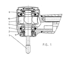
図1は、歯科用手用器具の正面部分を示す。この図は、上部ケーシング1を取り付けた状態の歯科用タービンハンドピースの正面部分の断面図である。タービンハンドピースは、動力工具3のための回転子4を備えた回転子軸2を、転がり軸受5,6を用いた既知の方法で支えている。回転要素(本実施例ではボール)が、ボールケージ10,11により間隔をあけて配置されている。
Even if coating lubricants and additional lubricants are selected that are compatible with prior art lubricants, conventional maintenance and lubrication using oils will not result in loss of coating properties. By providing a lubricant composed of several layers, slipping and lubricating action between the lubricating layers is possible, and as a result, the lubricating ability is increased.
[Typical embodiment]
FIG. 1 shows the front part of a dental hand instrument. This figure is a cross-sectional view of the front portion of the dental turbine handpiece with the upper casing 1 attached. The turbine handpiece supports the
このタービンハンドピースにおいては、具体的には軸受5,6及び/またはケージ10,11をコーティングすることができる。
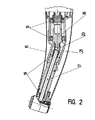
図2は、歯科用ハンドピースの断面図であり、2つの駆動軸部16,17が、保持スリーブ15内部に設置されている。いくつかの少なくとも部分的にコーティングされた転がり軸受18は、本実施例ではボール軸受18及び滑り軸受19として設計されており、取付けのために設けられている。歯車装置の歯車仕掛けは2つの歯車20,21から構成されている。
In this turbine handpiece, specifically, the
FIG. 2 is a cross-sectional view of the dental handpiece, and two drive shaft portions 16 and 17 are installed inside the holding
少なくとも部分的にコーティングされた転がり軸受18に、追加の潤滑剤を注入することが可能である。しかしながら、転がり軸受を滑り軸受に完全に置き換えることも可能であり、この場合には、対応するコーティングを行う。 It is possible to inject additional lubricant into the at least partially coated rolling bearing 18. However, it is also possible to completely replace the rolling bearing with a sliding bearing, in which case a corresponding coating is applied.
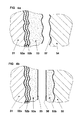
図3は、潤滑剤の構造の第1変形例としての多機能ハイブリッドポリマー層の構造設計図である。
保護層42は基体41の表面に設けられる。圧力安定層43をその上に設け、その次には機能層としてのポリマー層44を設ける。これらの層は、図において縦に拡大して表示されている。層全体の厚さは1−10μmである。
FIG. 3 is a structural design diagram of a multifunctional hybrid polymer layer as a first modification of the structure of the lubricant.
The
ハイブリッドポリマー層の利点は、各層が特別な機能(例えば、不動態化、耐摩耗化、圧力安定化、高潤滑作用等)を働かせることができることである。本実施例においても、コーティングは、コーティングされる物体の形には依存せず、層厚及び層数は、個別に調整可能である。本実施例のポリマーは、平らで均質な表面を形成する。 The advantage of the hybrid polymer layer is that each layer can perform special functions (for example, passivation, wear resistance, pressure stabilization, high lubrication, etc.). Also in this embodiment, the coating does not depend on the shape of the object to be coated, and the layer thickness and the number of layers can be adjusted individually. The polymer of this example forms a flat and homogeneous surface.
ポリマー層の内部構造は、同一の物質の様々なシートから構成されることができる。これらのシートは、シート間の潤滑処理により潤滑を理想的に維持することができる。さらに、例えば組立ての間に、ポリマー結合された潤滑剤を組み込むことが可能であり、未結合の潤滑剤を加えることもできる。潤滑許容量は、個々の層の相互作用により正確に設定できる。 The internal structure of the polymer layer can be composed of various sheets of the same material. These sheets can ideally maintain lubrication by a lubrication process between the sheets. In addition, polymer-bonded lubricants can be incorporated, for example during assembly, and unbound lubricants can be added. The lubrication allowance can be set accurately by the interaction of the individual layers.
図4aは、基体51を示し、基体51には、移行層52a及び支持層52b、次いで潤滑剤を含むまたは形成する機能層53が配置されている。移行層52aは、基体51への接続を確立し、支持層52bは、圧力補正を可能にする。この代わりに、たった1つの層あるいは2つの層52a、52b以外の層を設けることもできる。キャリヤ層及び機能層のどちらも機能層53の反対側にある本体54に設けられることはない。
FIG. 4a shows a
回転処理は、それと同時に起きる処理と共に、図4bに示すように、コーティング分布に変化をもたらす。回転処理により、機能層53から対をなす副体58へ材料が移動し、副体58に、機能層53bとして配置される。さらに、左右対称に滑らかな減摩面55,56が、基体51の機能層53aまたは機能層53b上に形成される。
The rotation process, together with the process that occurs simultaneously, causes a change in the coating distribution, as shown in FIG. 4b. By the rotation process, the material moves from the
機能層53は、金属ドープされたDCL層であってもよい。これらの層は、例えば磨耗防止のために使用され、具体的には基体51,54である隣接した減摩体同士の接触を妨げる。機能層全体の特性は、例えば別々の層52a及び52bにより個々に調整することができる。第1の変形例においては、このような層の機能層53の摩擦係数は、0.03である。
The
潤滑剤(本実施例では乾いた潤滑層)としては、機能層53が、追加的に、薄層状の改良二硫化タングステンから構成され、分子結合をなし、これにより同時にキャリヤ材料との物理的な接続を確立するという特徴がある。この結果、毒性または腐食作用を持たず、最も重要なことには、オイル、グリース、溶媒、ベンゼン、アルコールに適合する保護層が回転パス全体に広がる。
As a lubricant (in this embodiment, a dry lubricating layer), the
第2の実施例において、金属ドープしたDCL層(WC/Cとも称される)を用いた表面コーティングには、乾いた潤滑特性を有する硬質層が含まれる。硬質層の固さは1000HVである。硬質層の層構造には、中間クロム層及びいくつかの薄層状WC/C層が含まれる。それらの層の全体的な凝集性は良好である。全体的な層の厚さが1−4μmの場合、接着力も非常に良好である。このような層は300℃の耐熱性を持ち、表面構造が均一に滑らかな場合には、理論上の摩擦係数が0.2となる。 In a second embodiment, the surface coating using a metal doped DCL layer (also referred to as WC / C) includes a hard layer with dry lubrication properties. The hardness of the hard layer is 1000 HV. The layer structure of the hard layer includes an intermediate chromium layer and several thin WC / C layers. The overall cohesion of these layers is good. When the overall layer thickness is 1-4 μm, the adhesion is also very good. Such a layer has a heat resistance of 300 ° C., and when the surface structure is uniformly smooth, the theoretical coefficient of friction is 0.2.
設定により、潤滑の潤滑面を、結合潤滑剤または非結合潤滑剤により定めることができる。 Depending on the setting, the lubricating surface of the lubrication can be defined by a bonded lubricant or a non-bonded lubricant.
Claims (28)
Applications Claiming Priority (2)
| Application Number | Priority Date | Filing Date | Title |
|---|---|---|---|
| DE10259003A DE10259003A1 (en) | 2002-12-16 | 2002-12-16 | Slide bearing, in particular to be used in dental tool, comprising parts permanently coated with lubricant of suitable kind |
| PCT/DE2003/004125 WO2004055402A1 (en) | 2002-12-16 | 2003-12-12 | Antifriction bearing comprising integrated lubricating material |
Publications (2)
| Publication Number | Publication Date |
|---|---|
| JP2006509975A true JP2006509975A (en) | 2006-03-23 |
| JP2006509975A5 JP2006509975A5 (en) | 2007-02-01 |
Family
ID=32336404
Family Applications (1)
| Application Number | Title | Priority Date | Filing Date |
|---|---|---|---|
| JP2004559608A Pending JP2006509975A (en) | 2002-12-16 | 2003-12-12 | Rolling bearing with composite lubricating material |
Country Status (6)
| Country | Link |
|---|---|
| EP (1) | EP1573215A1 (en) |
| JP (1) | JP2006509975A (en) |
| AU (1) | AU2003294656A1 (en) |
| BR (1) | BR0317378A (en) |
| DE (1) | DE10259003A1 (en) |
| WO (1) | WO2004055402A1 (en) |
Families Citing this family (6)
| Publication number | Priority date | Publication date | Assignee | Title |
|---|---|---|---|---|
| DE102006057484B4 (en) * | 2006-12-06 | 2010-05-12 | Schaeffler Kg | Rolling bearings with a surface coating |
| DE102007015103A1 (en) | 2007-03-29 | 2008-10-02 | Schaeffler Kg | roller bearing |
| DE102009038410A1 (en) | 2009-08-21 | 2011-02-24 | Schaeffler Technologies Gmbh & Co. Kg | Constructional element i.e. roller bearing, has tribological loaded components movable relative to each other, and line section arranged outside contact region with reduced adhesive strength and/or wettability for lubricant |
| DE102010013630A1 (en) | 2010-04-01 | 2011-10-06 | Aktiebolaget Skf | Bearing ring of a sliding or roller bearing |
| DE102014104599B8 (en) | 2014-04-01 | 2019-01-17 | Thyssenkrupp Ag | roller bearing |
| DE102015211125B4 (en) * | 2015-06-17 | 2019-04-18 | Schaeffler Technologies AG & Co. KG | Cage for a rolling bearing and method of making such a cage |
Citations (2)
| Publication number | Priority date | Publication date | Assignee | Title |
|---|---|---|---|---|
| JPH0788853B2 (en) * | 1990-07-16 | 1995-09-27 | 株式会社安川電機 | Rolling bearing |
| JP2002349577A (en) * | 2001-05-29 | 2002-12-04 | Nsk Ltd | Rolling slide member |
Family Cites Families (27)
| Publication number | Priority date | Publication date | Assignee | Title |
|---|---|---|---|---|
| JPS5557717A (en) * | 1978-10-25 | 1980-04-28 | Koyo Seiko Co Ltd | Rolling bearing |
| US5207513A (en) * | 1990-11-30 | 1993-05-04 | Ntn Corporation | Rolling bearing with solid lubricant |
| JP3021923B2 (en) * | 1992-02-27 | 2000-03-15 | エヌティエヌ株式会社 | Rolling bearings for semiconductor manufacturing equipment |
| JPH06193637A (en) * | 1992-12-25 | 1994-07-15 | Ntn Corp | Rolling bearing |
| JP3535558B2 (en) * | 1994-03-07 | 2004-06-07 | 株式会社東芝 | Sliding member, rolling bearing and rotating anode X-ray tube |
| JPH0874862A (en) * | 1994-09-06 | 1996-03-19 | Hitachi Ltd | Solid lubricating bearing |
| JPH0893774A (en) * | 1994-09-21 | 1996-04-09 | Ntn Corp | Solid lubricating rolling bearing |
| JP3002957B2 (en) * | 1995-09-11 | 2000-01-24 | 光洋精工株式会社 | Rolling bearing and method of forming lubricating film for rolling bearing |
| RU2095653C1 (en) * | 1996-09-25 | 1997-11-10 | Константин Дмитриевич Семкин | Bearing with permanently lubricating layer and method of manufacturing same |
| JPH1151066A (en) * | 1997-07-30 | 1999-02-23 | Nippon Seiko Kk | Roller bearing filled with lubricant contained polymer and manufacture thereof |
| NL1007046C2 (en) * | 1997-09-16 | 1999-03-17 | Skf Ind Trading & Dev | Coated rolling bearing. |
| JPH11201175A (en) * | 1998-01-07 | 1999-07-27 | Koyo Seiko Co Ltd | Rolling bearing |
| NL1009170C2 (en) * | 1998-05-14 | 1999-11-16 | Skf Eng & Res Centre Bv | Coated rolling bearing. |
| JP2000136828A (en) * | 1998-11-04 | 2000-05-16 | Koyo Seiko Co Ltd | Rolling bearing |
| US6296393B1 (en) * | 1998-12-17 | 2001-10-02 | Nsk Ltd. | Lubricant-containing polymer-filled rolling bearing and process for the production thereof |
| JP3772944B2 (en) * | 1998-12-17 | 2006-05-10 | 日本精工株式会社 | Roller bearings filled with polymer containing lubricant |
| WO2001033091A1 (en) * | 1999-10-29 | 2001-05-10 | The Timken Company | Antifriction bearing for use in a corrosive environment |
| JP3961739B2 (en) * | 2000-04-19 | 2007-08-22 | 株式会社ジェイテクト | Rolling bearing |
| JP3811596B2 (en) * | 2000-06-15 | 2006-08-23 | 株式会社ジェイテクト | Rolling motion parts |
| JP2002122152A (en) * | 2000-10-13 | 2002-04-26 | Nsk Ltd | Rolling member |
| JP2002195276A (en) * | 2000-12-27 | 2002-07-10 | Nsk Ltd | Rolling bearing |
| US6764307B2 (en) * | 2001-03-28 | 2004-07-20 | Minebea Company, Ltd. | Polymer-metal composition retainer for self-lubricating bearing |
| JP2003013960A (en) * | 2001-06-27 | 2003-01-15 | Nsk Ltd | High speed rolling bearing |
| US6994474B2 (en) * | 2001-05-29 | 2006-02-07 | Nsk Ltd. | Rolling sliding member and rolling apparatus |
| JP2002357225A (en) * | 2001-05-31 | 2002-12-13 | Nsk Ltd | Rolling bearing |
| DE10145405A1 (en) * | 2001-09-14 | 2003-04-03 | Fraunhofer Ges Forschung | Rolling bearing used in cylinder rollers comprises an inner and an outer running ring each having a running path arranged opposite each other and arranged between rolling bodies |
| NL1019860C2 (en) * | 2002-01-30 | 2003-08-05 | Skf Ab | Roller bearing with a ceramic rolling element and steel inner or outer ring. |
-
2002
- 2002-12-16 DE DE10259003A patent/DE10259003A1/en not_active Withdrawn
-
2003
- 2003-12-12 AU AU2003294656A patent/AU2003294656A1/en not_active Abandoned
- 2003-12-12 JP JP2004559608A patent/JP2006509975A/en active Pending
- 2003-12-12 EP EP03785573A patent/EP1573215A1/en not_active Withdrawn
- 2003-12-12 BR BR0317378-0A patent/BR0317378A/en not_active Application Discontinuation
- 2003-12-12 WO PCT/DE2003/004125 patent/WO2004055402A1/en not_active Application Discontinuation
Patent Citations (2)
| Publication number | Priority date | Publication date | Assignee | Title |
|---|---|---|---|---|
| JPH0788853B2 (en) * | 1990-07-16 | 1995-09-27 | 株式会社安川電機 | Rolling bearing |
| JP2002349577A (en) * | 2001-05-29 | 2002-12-04 | Nsk Ltd | Rolling slide member |
Also Published As
| Publication number | Publication date |
|---|---|
| AU2003294656A1 (en) | 2004-07-09 |
| DE10259003A1 (en) | 2004-06-24 |
| WO2004055402A1 (en) | 2004-07-01 |
| EP1573215A1 (en) | 2005-09-14 |
| BR0317378A (en) | 2005-11-16 |
Similar Documents
| Publication | Publication Date | Title |
|---|---|---|
| JP4244106B2 (en) | Coated rolling bearing | |
| JP4897343B2 (en) | Bearing member | |
| DellaCorte | The evaluation of a modified chrome oxide based high temperature solid lubricant coating for foil gas bearings | |
| US20090311476A1 (en) | Component Unit, in particular a molded component, with a coating | |
| JPH02271106A (en) | Sliding bearing device | |
| JP2006509975A (en) | Rolling bearing with composite lubricating material | |
| JPH102338A (en) | Lubricating rolling contact device, lubricating method lubricating composition and ceramic rolling element | |
| JP3740178B2 (en) | SCREW ROTOR, SCREW COMPRESSOR, AND METHOD FOR PRODUCING THE SAME | |
| JP2009041659A (en) | Bearing device | |
| JP6481798B2 (en) | Rolling bearing | |
| JP2008180374A (en) | Rolling bearing | |
| JP3121701B2 (en) | Rolling bearings for semiconductor manufacturing equipment | |
| KR20030074648A (en) | Rolling bearing comprising a powder metallurgical component | |
| JPH10205541A (en) | Rolling bearing | |
| JP2007085363A (en) | Bearing and its manufacturing method | |
| US20060274985A1 (en) | Antifriction bearing comprising integrated lubricating material | |
| US20060115788A1 (en) | Dental hand instrument comprising components which can be displaced in relation to each other | |
| US20140234064A1 (en) | Sealing System, An Industrial Robot With A Sealing System, And Method For Providing A Sealing Surface | |
| JP2503966Y2 (en) | Rolling bearing | |
| JPH11257363A (en) | Rolling bearing | |
| JP2010255682A (en) | Dlc film separation preventive method of rolling sliding member and usage of rolling support device | |
| JP2006321838A (en) | Rolling apparatus | |
| JP2007177836A (en) | Rolling bearing | |
| JPS63167125A (en) | Rolling bearing | |
| JP2019027545A (en) | Rolling bearing and manufacturing method thereof |
Legal Events
| Date | Code | Title | Description |
|---|---|---|---|
| A521 | Written amendment |
Free format text: JAPANESE INTERMEDIATE CODE: A523 Effective date: 20061211 |
|
| A621 | Written request for application examination |
Free format text: JAPANESE INTERMEDIATE CODE: A621 Effective date: 20061211 |
|
| A131 | Notification of reasons for refusal |
Free format text: JAPANESE INTERMEDIATE CODE: A131 Effective date: 20091020 |
|
| A601 | Written request for extension of time |
Free format text: JAPANESE INTERMEDIATE CODE: A601 Effective date: 20100119 |
|
| A602 | Written permission of extension of time |
Free format text: JAPANESE INTERMEDIATE CODE: A602 Effective date: 20100126 |
|
| A02 | Decision of refusal |
Free format text: JAPANESE INTERMEDIATE CODE: A02 Effective date: 20100420 |