WO2018142826A1 - 車両用空調装置 - Google Patents
車両用空調装置 Download PDFInfo
- Publication number
- WO2018142826A1 WO2018142826A1 PCT/JP2017/047108 JP2017047108W WO2018142826A1 WO 2018142826 A1 WO2018142826 A1 WO 2018142826A1 JP 2017047108 W JP2017047108 W JP 2017047108W WO 2018142826 A1 WO2018142826 A1 WO 2018142826A1
- Authority
- WO
- WIPO (PCT)
- Prior art keywords
- air
- battery
- blower
- vehicle
- conditioning case
- Prior art date
- Legal status (The legal status is an assumption and is not a legal conclusion. Google has not performed a legal analysis and makes no representation as to the accuracy of the status listed.)
- Ceased
Links
Images


Classifications
-
- B—PERFORMING OPERATIONS; TRANSPORTING
- B60—VEHICLES IN GENERAL
- B60K—ARRANGEMENT OR MOUNTING OF PROPULSION UNITS OR OF TRANSMISSIONS IN VEHICLES; ARRANGEMENT OR MOUNTING OF PLURAL DIVERSE PRIME-MOVERS IN VEHICLES; AUXILIARY DRIVES FOR VEHICLES; INSTRUMENTATION OR DASHBOARDS FOR VEHICLES; ARRANGEMENTS IN CONNECTION WITH COOLING, AIR INTAKE, GAS EXHAUST OR FUEL SUPPLY OF PROPULSION UNITS IN VEHICLES
- B60K1/00—Arrangement or mounting of electrical propulsion units
- B60K1/04—Arrangement or mounting of electrical propulsion units of the electric storage means for propulsion
-
- B—PERFORMING OPERATIONS; TRANSPORTING
- B60—VEHICLES IN GENERAL
- B60H—ARRANGEMENTS OF HEATING, COOLING, VENTILATING OR OTHER AIR-TREATING DEVICES SPECIALLY ADAPTED FOR PASSENGER OR GOODS SPACES OF VEHICLES
- B60H1/00—Heating, cooling or ventilating devices
-
- B—PERFORMING OPERATIONS; TRANSPORTING
- B60—VEHICLES IN GENERAL
- B60H—ARRANGEMENTS OF HEATING, COOLING, VENTILATING OR OTHER AIR-TREATING DEVICES SPECIALLY ADAPTED FOR PASSENGER OR GOODS SPACES OF VEHICLES
- B60H1/00—Heating, cooling or ventilating devices
- B60H1/00271—HVAC devices specially adapted for particular vehicle parts or components and being connected to the vehicle HVAC unit
- B60H1/00278—HVAC devices specially adapted for particular vehicle parts or components and being connected to the vehicle HVAC unit for the battery
-
- B—PERFORMING OPERATIONS; TRANSPORTING
- B60—VEHICLES IN GENERAL
- B60H—ARRANGEMENTS OF HEATING, COOLING, VENTILATING OR OTHER AIR-TREATING DEVICES SPECIALLY ADAPTED FOR PASSENGER OR GOODS SPACES OF VEHICLES
- B60H1/00—Heating, cooling or ventilating devices
- B60H1/32—Cooling devices
-
- B—PERFORMING OPERATIONS; TRANSPORTING
- B60—VEHICLES IN GENERAL
- B60K—ARRANGEMENT OR MOUNTING OF PROPULSION UNITS OR OF TRANSMISSIONS IN VEHICLES; ARRANGEMENT OR MOUNTING OF PLURAL DIVERSE PRIME-MOVERS IN VEHICLES; AUXILIARY DRIVES FOR VEHICLES; INSTRUMENTATION OR DASHBOARDS FOR VEHICLES; ARRANGEMENTS IN CONNECTION WITH COOLING, AIR INTAKE, GAS EXHAUST OR FUEL SUPPLY OF PROPULSION UNITS IN VEHICLES
- B60K11/00—Arrangement in connection with cooling of propulsion units
- B60K11/06—Arrangement in connection with cooling of propulsion units with air cooling
-
- B—PERFORMING OPERATIONS; TRANSPORTING
- B60—VEHICLES IN GENERAL
- B60R—VEHICLES, VEHICLE FITTINGS, OR VEHICLE PARTS, NOT OTHERWISE PROVIDED FOR
- B60R16/00—Electric or fluid circuits specially adapted for vehicles and not otherwise provided for; Arrangement of elements of electric or fluid circuits specially adapted for vehicles and not otherwise provided for
- B60R16/08—Electric or fluid circuits specially adapted for vehicles and not otherwise provided for; Arrangement of elements of electric or fluid circuits specially adapted for vehicles and not otherwise provided for fluid
-
- B—PERFORMING OPERATIONS; TRANSPORTING
- B60—VEHICLES IN GENERAL
- B60H—ARRANGEMENTS OF HEATING, COOLING, VENTILATING OR OTHER AIR-TREATING DEVICES SPECIALLY ADAPTED FOR PASSENGER OR GOODS SPACES OF VEHICLES
- B60H1/00—Heating, cooling or ventilating devices
- B60H1/00271—HVAC devices specially adapted for particular vehicle parts or components and being connected to the vehicle HVAC unit
- B60H2001/003—Component temperature regulation using an air flow
Definitions
- the present disclosure relates to a vehicle air conditioner that supplies air to a vehicle interior and a battery housing space.
- Patent Document 1 a battery cooling device that cools a battery accommodated in a battery casing using air flowing inside an air conditioning unit for air conditioning in a vehicle interior is known (see, for example, Patent Document 1).
- Patent Document 1 in a configuration in which an evaporator and a heater core are arranged on the downstream side of the air flow of the blower, a cold air is supplied to the battery casing by connecting a communication duct communicating with the inside of the battery casing on the downstream side of the air flow of the blower.
- Patent Document 1 discloses an air-mix type air conditioner unit that adjusts the mixing ratio of cold air cooled by an evaporator and warm air heated by a heater core to adjust the temperature of air blown into the vehicle interior. Yes.
- This disclosure is intended to provide a vehicle air conditioner capable of suppressing a decrease in air conditioning performance in a vehicle interior when battery cooling and air conditioning in the vehicle interior are performed in parallel.
- a vehicle air conditioner includes: An air conditioning case with an air ventilation path inside; An indoor blower that generates an air flow toward the passenger compartment; A communication duct that communicates the inside of the air conditioning case with the battery housing space.
- a battery blower that guides the air flowing inside the air conditioning case to the battery housing space via the communication duct is disposed. And the communication duct is connected to the site
- the vehicle air conditioner according to the present disclosure can independently secure the air volume necessary for cooling the battery and the air volume required for air conditioning in the vehicle interior. When carrying out in parallel, it becomes possible to suppress that the air-conditioning performance in a vehicle interior falls.
- the vehicle air conditioner 1 includes an indoor air conditioning unit 10 that air-conditions a vehicle interior, a battery unit 50 on which a battery 51 is mounted, and a control device 100.
- the indoor air conditioning unit 10 is disposed on the inside of an instrument panel disposed at the front of the vehicle interior.
- the indoor air conditioning unit 10 includes an air conditioning case 12, an indoor / outdoor air door (not shown), an evaporator 16, an indoor blower 18, a heater core (not shown), an air mix door (not shown), and the like.
- the air conditioning case 12 constitutes an outer shell of the indoor air conditioning unit 10 and an air passage 13 through which air flowing toward the vehicle interior flows is formed.
- the air conditioning case 12 has a certain degree of elasticity and is formed of a resin (for example, polypropylene) that is excellent in strength.
- the air conditioning case 12 is actually configured as an assembly of a plurality of divided cases for convenience in resin molding, assembly of internal parts, and the like. Specifically, the air conditioning case 12 is configured by fastening a plurality of divided cases with fastening members such as screws and clips.
- the air conditioning case 12 has an outside air introduction section for introducing outside air (that is, outside air) and an inside air introduction section that introduces inside room air (that is, inside air) upstream of the air flow of the indoor fan 18. Are formed adjacent to each other.
- an inside / outside air door for adjusting the opening ratio of the outside air introduction part and the inside air introduction part is arranged inside the air conditioning case 12.
- the air conditioning case 12 has a defroster opening, a face opening, and a foot opening on the downstream side of the air flow of the indoor fan 18.
- the defroster opening is an opening for supplying air toward the inside of the window glass of the vehicle.
- the face opening is an opening for supplying air toward the upper body side of the passenger in the vehicle interior.
- the foot opening is an opening for supplying air toward the lower body side of the passenger in the passenger compartment.
- the blowing mode door which adjusts the opening / closing state of each above-mentioned opening part is provided in the inside of the air-conditioning case 12. FIG.
- an air filter 14 that collects foreign matters such as dust contained in the air introduced from the outside air introduction portion or the inside air introduction portion is disposed.
- the air filter 14 includes a filter frame, a filter element, and the like (not shown).
- the air conditioning case 12 houses an evaporator 16 that functions as a cooling heat exchanger for cooling the air flowing through the air conditioning case 12.
- the evaporator 16 is arrange
- the evaporator 16 of the present embodiment is configured by a low-pressure heat exchanger in a vapor compression refrigeration cycle. That is, the evaporator 16 is a heat exchanger that cools the air that flows inside the air conditioning case 12 by evaporating the low-temperature and low-pressure fluid (that is, the refrigerant) that flows inside through heat exchange with air.
- the evaporator 16 has a thin shape with a rectangular outer shape.
- the air conditioner case 12 is provided with an indoor blower 18 that generates an air flow toward the vehicle interior.
- the indoor blower 18 is disposed on the air flow downstream side of the evaporator 16 inside the air conditioning case 12.
- the indoor blower 18 includes a fan 181 and an electric motor 182 that rotationally drives the fan 181.
- the indoor blower 18 of the present embodiment is arranged so that the extending direction of the fan axis CL extends along the thickness direction of the evaporator 16.
- the fan 181 is configured to blow out air sucked from the extending direction of the fan axis CL in a direction intersecting the fan axis CL.
- the fan 181 according to the present embodiment is a centrifugal fan having characteristics that a dynamic pressure is smaller than that of an axial fan and a static pressure is increased.
- centrifugal fans are classified into sirocco fans, radial fans, and turbo fans according to their blade shapes.
- the fan 181 of the present embodiment is a turbo fan that can obtain a high static pressure among centrifugal fans.
- the centrifugal fan may be composed of a sirocco fan or a radial fan other than the turbo fan.
- the air conditioning case 12 is formed with a fan accommodating portion 15 that accommodates the fan 181.
- the fan accommodating portion 15 is formed on the air flow downstream side of the evaporator 16 in the air conditioning case 12.
- the fan accommodating portion 15 is provided with an air suction portion 151 that guides air into the fan 181.
- an air blowing portion 152 that blows an airflow generated inside the fan 181 is set in the fan housing portion 15 on the air blowing side of the fan 181.
- the fan accommodating portion 15 of the present embodiment is a partition portion 153 that partitions an upstream space 131 on the upstream side of the air flow of the indoor fan 18 and a downstream space 132 on the downstream side of the air flow of the indoor fan 18 in the ventilation path 13. It is comprised including.
- the indoor blower 18 of the present embodiment has an arrangement configuration in which the air suction part 151 faces the air outflow surface 161 in the evaporator 16 so that the air that has passed through the evaporator 16 is easily guided to the air suction part 151. It has become.
- the evaporator 16 of the present embodiment is arranged with the air outflow surface 161 facing the air suction portion 151 so as to be visible from the air suction portion 151.
- a heater core (not shown) is arranged on the downstream side of the air flow of the air blowing part 152.
- the heater core is a heating heat exchanger that heats the air that has passed through the evaporator 16.
- a heat exchanger that heats the air that has passed through the evaporator 16 using cooling water that cools the internal combustion engine as a heat source can be employed.
- a cold air bypass passage (not shown) is formed on the downstream side of the air blowing portion 152.
- the cold air bypass passage is a passage through which the airflow blown from the indoor blower 18 flows around the heater core.
- an air mix door is arranged in the air conditioning case 12.
- the air mix door is a member that adjusts the air volume ratio of the air passing through the heater core and the air passing through the cold air bypass passage.
- the above-described defroster opening, face opening, and foot opening are formed on the downstream side of the air flow in the heater core and the cold air bypass passage.
- an intermediate opening 122 is formed in an intermediate wall surface 121 that forms the ventilation path 13 from the evaporator 16 to the air suction side of the indoor blower 18.
- the intermediate opening 122 is an opening for leading the cool air cooled by the evaporator 16 to a battery housing space 52a described later.
- the intermediate opening 122 is preferably formed at a site where the condensed water generated in the evaporator 16 in the intermediate wall surface 121 is difficult to adhere.
- the intermediate opening 122 is connected to a communication duct 30 that allows the inside of the air conditioning case 12 to communicate with a battery housing space 52a described later.
- One end side of the communication duct 30 is connected to a portion of the air conditioning case 12 located on the upstream side of the air flow of the indoor blower 18, that is, the intermediate opening 122 of the intermediate wall surface portion 121.
- the communication duct 30 is connected to an air suction port 521 formed in the battery case 52 at the other end.
- the battery unit 50 is mounted under the floor of the vehicle.
- the mounting position of the battery unit 50 is not limited to the under floor of the vehicle, and may be mounted on the lower side of the trunk room or the seat of the vehicle.
- the battery unit 50 is configured to be able to cool the battery 51 using the cold air generated by the indoor air conditioning unit 10.
- the battery unit 50 includes a battery 51, a battery case 52, an exhaust duct 54, and a battery blower 56.
- the battery 51 supplies a predetermined high voltage to the in-vehicle device.
- the battery 51 is composed of, for example, a large-capacity battery that supplies electric power to a traveling motor that generates driving force during vehicle traveling.
- the battery 51 is composed of a chargeable / dischargeable secondary battery.
- the battery 51 is configured as an assembled battery in which battery cells such as lithium ion batteries are electrically connected in series or in parallel, for example.
- the battery case 52 constitutes an outer shell of the battery unit 50, and a battery housing space 52a for housing the battery 51 is formed therein.
- the battery housing space 52 a also functions as a ventilation path through which the cold air generated by the indoor air conditioning unit 10 flows through the communication duct 30.
- the battery case 52 is formed with an air suction port 521 for introducing air into the battery housing space 52a and an air exhaust port 522 for extracting air from the battery housing space 52a.
- the communication duct 30 is connected to the air suction port 521.
- an exhaust duct 54 that guides the air in the battery housing space 52a to the outside of the vehicle is connected to the air discharge port 522.
- a battery blower 56 is disposed in the battery housing space 52a.
- the battery blower 56 is a blower that guides the air flowing through the air conditioning case 12 to the battery housing space 52 a via the communication duct 30.
- the battery blower 56 of the present embodiment is disposed on the upstream side of the air flow from the battery 51 in the battery housing space 52a. Specifically, the battery blower 56 is disposed in a position closer to the communication duct 30 than the battery 51 in the battery housing space 52a. In other words, the battery blower 56 is disposed at a position farther from the exhaust duct 54 than the battery 51.
- the battery blower 56 is an electric blower including a fan and an electric motor (not shown).
- the fan of the battery blower 56 is composed of, for example, an axial fan. Note that the fan of the battery blower 56 is not limited to an axial fan, and may be a centrifugal fan or the like.
- the control apparatus 100 which comprises the electronic control part of the vehicle air conditioner 1 is demonstrated.
- the control device 100 includes a known microcomputer including a CPU, a storage unit, and the like, and peripheral circuits thereof.
- the control device 100 is a device that performs various calculations and processes based on a control program stored in a storage unit or the like.
- the storage unit of the control device 100 is configured with a non-transitional tangible storage medium.
- An air conditioning sensor group such as an inside air sensor 101 for detecting the inside air temperature, an outside air sensor 102 for detecting the outside air temperature, and a solar radiation sensor 103 for detecting the amount of solar radiation into the vehicle interior is connected to the input side of the control device 100. Yes.
- a battery temperature sensor 104 that detects the temperature of the battery 51 is connected to the input side of the control device 100.
- the battery temperature sensor 104 is composed of, for example, a temperature sensor that detects the surface temperature of the battery 51.
- an operation unit 110 operated by an occupant is connected to the input side of the control device 100.
- the operation unit 110 is provided with an air conditioning operation switch, a temperature setting switch for setting a set temperature in the passenger compartment, and the like.
- a control target device whose operation is controlled by a control signal output from the control device 100 is connected to the output side of the control device 100.
- the indoor blower 18, the battery blower 56, and the like are connected to the control device 100 as control target devices.
- control device 100 a plurality of control units configured by hardware and software for controlling the control target device connected to the output side are integrated.
- the control device 100 is, for example, a mode control unit that performs switching control of operation modes such as an indoor air conditioning mode that simply air-conditions the vehicle interior, a battery cooling mode that performs air conditioning in the vehicle interior and cooling of the battery 51 in parallel. 100a is aggregated.
- the vehicle air conditioner 1 can switch the operation mode between an indoor air conditioning mode and a battery cooling mode. Specifically, in the vehicle air conditioner 1, when the air conditioning operation switch of the operation unit 110 is turned on while power is supplied, the control device 100 executes a mode switching process for switching the operation mode.
- Each control step of the mode switching process shown in FIG. 2 constitutes a function implementing unit that implements various functions executed by the control device 100.
- control device 100 reads the sensor signals of the various sensors 101 to 104 and the operation signals of the operation unit 110 in step S10. Subsequently, in step S20, control device 100 determines whether or not the battery temperature detected by battery temperature sensor 104 is equal to or lower than the appropriate upper limit temperature.
- the battery 51 may generate heat and become high temperature at the time of charging or discharging to supply power to a traveling motor (not shown).
- a predetermined temperature for example, 40 ° C.
- the appropriate upper limit temperature is set to 40 ° C. or less, for example.
- the appropriate upper limit temperature is desirably set as appropriate according to the type of battery constituting the battery 51.
- step S20 when it is determined that the battery temperature is equal to or lower than the appropriate upper limit temperature, it is considered that cooling of the battery 51 is unnecessary. decide.
- the control device 100 controls the indoor blower 18 to the operating state in a state where the operation of the battery blower 56 is stopped in the indoor air conditioning mode.
- the control device 100 controls the operation of devices to be controlled such as the indoor blower 18 based on a target blowing temperature TAO that is a target temperature of air blown into the vehicle interior in the indoor air conditioning mode.
- the control device 100 calculates a target blowing temperature TAO that is a target temperature of air blown into the vehicle interior in the indoor air conditioning mode.
- the control apparatus 100 calculates TAO by the following [Equation 1], for example.
- TAO Kset ⁇ Tset ⁇ Kr ⁇ Tr ⁇ Kam ⁇ Tam ⁇ Ks ⁇ Ts + C [Equation 1]
- Tr is a detection value of the inside air sensor 101
- Tam is a detection value of the outside air sensor 102
- Ts is a detection value of the solar radiation sensor 103.
- Kset, Kr, Kam, and Ks are control gains
- C is a correction constant.
- the control apparatus 100 refers to the control map previously memorize
- control device 100 controls the indoor blower 18 to the operating state while the operation of the battery blower 56 is stopped, so that an air flow toward the vehicle interior is generated inside the air-conditioning case 12. To do.
- the airflow introduced from the outside air introduction portion or the inside air introduction portion flows into the evaporator 16 via the air filter 14.
- the air flow is cooled to a predetermined temperature by the evaporator 16 and then sucked into the indoor blower 18 from the air suction portion 151.
- the air sucked into the indoor blower 18 is blown out from the inside of the fan 181 toward the outside in the radial direction.
- This airflow flows in the downstream space 132 in the ventilation path 13.
- the downstream space 132 after passing through a heater core or a cold air bypass passage (not shown), the air is blown into the vehicle interior through any of the openings.
- step S20 if it is determined that the battery temperature exceeds the appropriate upper limit temperature, it is considered that the battery 51 needs to be cooled. Therefore, the control device 100 sets the operation mode to battery in step S40. Decide on cooling mode.
- the control device 100 controls both the indoor fan 18 and the battery fan 56 to the operating state in the battery cooling mode.
- the control object apparatus by the side of the indoor air conditioning unit 10 at the time of battery cooling mode, it is controlled by the control apparatus 100 to the operating state similar to the time of indoor air conditioning mode.
- the control device 100 controls the battery blower 56 so that the rotation speed becomes a predetermined reference rotation speed in the battery cooling mode.
- the control device 100 may be configured to control the battery blower 56 so that the number of revolutions increases as the battery temperature increases in the battery cooling mode.
- both the indoor fan 18 and the battery fan 56 are controlled to be in an operating state by the control device 100, so that the air flow toward the vehicle interior and the battery accommodating space 52 a are entered into the air conditioning case 12. Airflow is generated.
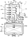
- the airflow introduced from the outside air introduction portion or the inside air introduction portion flows into the evaporator 16 via the air filter 14, as indicated by an arrow AFE in FIG.
- the evaporator 16 is cooled to a predetermined temperature.
- the air cooled by the evaporator 16 is sucked into the indoor blower 18 from the air suction portion 151 as indicated by an arrow AFS in FIG. 3 and through the communication duct 30 as indicated by an arrow AFB1 in FIG. Is sucked into the battery blower 56 in the battery housing space 52a.
- the air sucked into the indoor blower 18 is blown out from the inside of the fan 181 toward the outside in the radial direction, as indicated by an arrow AFD in FIG.
- the airflow passes through a heater core or a cold air bypass passage (not shown) and is then blown out into the vehicle compartment through one of the openings.
- the air sucked into the battery blower 56 is blown out to the battery 51 located on the downstream side of the air flow of the battery blower 56 as indicated by an arrow AFB2 in FIG.
- the battery 51 is cooled.
- the air that has absorbed heat from the battery 51 in the battery housing space 52a is discharged to the outside of the vehicle through the exhaust duct 54 as indicated by an arrow AFB3 in FIG.
- FIG. 4 is a schematic cross-sectional view of a vehicle air conditioner CE of a comparative example.
- the same reference numerals are assigned to the same configuration as the vehicle air conditioner 1 of the present embodiment for the vehicle air conditioner CE of the comparative example.
- the indoor blower BF in the air conditioning case HC is disposed on the upstream side of the air flow of the evaporator 16.
- the air conditioning case HC is connected to a communication duct CD that guides the air that has passed through the evaporator 16 to the battery housing space 52 a on the downstream side of the air flow of the evaporator 16.
- the battery unit BU of the vehicle air conditioner CE of the comparative example is not provided with a dedicated blower that supplies air to the battery BT.
- Other configurations are the same as those of the vehicle air conditioner 1 of the present embodiment.
- the air blown from the indoor blower BF flows into the evaporator 16.
- a part of the air that has passed through the evaporator 16 is supplied to the battery BT via the communication duct CD, and the rest passes through a heater core or a cold air bypass passage (not shown), and then passes through any of the openings. It is blown into the room.
- the vehicle air conditioner CE of the comparative example in the configuration in which the communication duct CD communicating with the battery housing space 52a is connected to the downstream side of the air flow of the indoor blower BF, a part of the air flow generated in the indoor blower BF is a battery. It flows to the unit BU side. For this reason, in the vehicle air conditioner CE of the comparative example, when the battery BT is cooled, the amount of air blown into the passenger compartment is reduced. This is not preferable because it causes the air conditioning feeling of the occupant to deteriorate.
- the air mix type indoor air conditioning unit HU when the cool air cooled by the evaporator 16 is introduced to the battery BT side, the mixing ratio of the cold air and the hot air in the indoor air conditioning unit HU changes. That is, the air mix type indoor air conditioning unit HU cannot properly adjust the temperature of the air blown into the vehicle interior.
- the indoor blower 18 is disposed inside the air conditioning case 12, and the battery blower 56 is disposed in the battery accommodating space 52a.
- the communication duct 30 that introduces cold air into the battery housing space 52a has a portion on the upstream side of the air flow of the indoor blower 18 in the air conditioning case 12 (that is, the intermediate wall surface portion 121). )It is connected to the.
- the vehicle air conditioner 1 according to the present embodiment can independently secure the air volume required for cooling the battery 51 and the air volume required for air conditioning in the passenger compartment. Therefore, the vehicle air conditioner 1 according to the present embodiment can suppress the deterioration of the air conditioning performance in the vehicle interior when the cooling of the battery 51 and the air conditioning of the vehicle interior are performed in parallel.
- the communication duct 30 of the present embodiment is connected between the evaporator 16 and the indoor blower 18 in the air conditioning case 12, so that the cool air cooled by the evaporator 16 by the battery blower 56 is stored in the battery. It can be introduced into the space 52a. According to this, the battery 51 can be sufficiently cooled by the cold air cooled by the evaporator 16 of the indoor air conditioning unit 10.
- the mounting position of the battery blower 56 in the battery unit 50 is different from the mounting position of the battery blower 56 in the first embodiment.
- the battery blower 56 of the present embodiment is disposed on the downstream side of the air flow of the battery 51 in the battery housing space 52a. Specifically, the battery blower 56 of this embodiment is disposed at a position closer to the exhaust duct 54 than the battery 51. In other words, the battery blower 56 of the present embodiment is arranged at a position farther from the communication duct 30 than the battery 51.
- vehicle air conditioner 1 of the present embodiment are the same as those of the first embodiment.
- the vehicle air conditioner 1 according to the present embodiment can obtain the effects obtained from the configuration common to the first embodiment, similarly to the first embodiment.
- the battery blower 56 when the battery blower 56 is operated, the electric motor or the like generates heat. For this reason, when the battery blower 56 is arranged on the upstream side of the air flow from the battery 51, there is a concern that the temperature of the air supplied to the battery 51 is increased by the heat of the battery blower 56.
- the battery blower 56 is disposed on the downstream side of the air flow of the battery 51 in the battery housing space 52a. According to this, since it is possible to prevent the temperature of the air supplied to the battery 51 from rising due to the heat generated when the battery blower 56 is activated, the battery 51 can be efficiently cooled. .
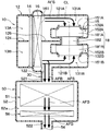
- the air conditioning case 12 is provided with a first partition wall portion 124 and a second partition wall portion 126 that divide the interior of the air conditioning case 12 into an inside air ventilation path 13A and an outside air ventilation path 13B.
- the first partition 124 is provided on the air flow upstream side of the air filter 14 in the air conditioning case 12.
- the second partition wall 126 is provided between the evaporator 16 and the indoor fan 18 in the air conditioning case 12.
- the indoor blower 18 of the present embodiment is a double fan type blower that drives two fans, a first fan 181A and a second fan 181B, by a single electric motor 182.
- the first fan 181A is a fan that generates an air flow in the inside air ventilation path 13A.
- the second fan 181B is a fan that generates an air current in the outside air ventilation path 13B.
- a first air suction portion 151A that guides air to the inside of the first fan 181A is set, and a second air suction portion 151B that guides air to the inside of the second fan 181B.
- the fan accommodating portion 15 is provided with a first air blowing portion 152A for blowing an air flow generated inside the first fan 181A, and a second air blowing portion 152B for blowing an air flow generated inside the second fan 181B. Is set.
- the indoor blower 18 is configured so that both the air suction portions 151A and 151B prevent the air that has passed through the evaporator 16 from flowing to one of the first air suction portion 151A and the second air suction portion 151B.
- the arrangement is such that it does not face the outflow surface 161 of the evaporator 16.
- the evaporator 16 of the present embodiment is arranged in a state where the air outflow surface 161 does not face the air suction portion 151 so that the evaporator 16 cannot be seen from the air suction portions 151A and 151B.
- the fan accommodating portion 15 causes the first upstream space 131A on the upstream side of the air flow of the indoor blower 18 and the downstream side of the air flow of the indoor blower 18 in the inside air ventilation path 13A. 1 is divided into a downstream space 132A.
- the air conditioning case 12 of the present embodiment is configured such that the fan accommodating portion 15 causes the second upstream space 131B on the upstream side of the air flow of the indoor fan 18 in the outside air ventilation path 13B and the downstream side of the air flow of the indoor fan 18 to the second side. 2 is divided into a downstream space 132B.
- the air conditioning case 12 forms a first intermediate wall surface part 121A that forms an inside air ventilation path 13A from the evaporator 16 to the first fan 181A, and an outside air ventilation path 13B that extends from the evaporator 16 to the second fan 181B. It has the 2nd intermediate wall surface part 121B.
- the second intermediate wall surface 121B is formed with an intermediate opening 122 for leading the cool air cooled by the evaporator 16 to the battery housing space 52a.
- the intermediate opening 122 is connected to a communication duct 30 that allows the inside of the air conditioning case 12 to communicate with the battery housing space 52a.
- vehicle air conditioner 1 of the present embodiment are the same as those of the second embodiment described above.
- vehicle air conditioner 1 according to the present embodiment can obtain the effects obtained from the configuration common to the second embodiment in the same manner as the above-described embodiment.
- the inside air tends to be more humid than the outside air due to the breathing of the occupant. For this reason, there is a concern that condensation may occur in the battery 51 in the configuration in which the inside air is introduced into the battery housing space 52a.
- the communication duct 30 forms the outside air ventilation path 13B in the air conditioning case 12 so that outside air is introduced into the battery housing space 52a in the battery cooling mode. (That is, connected to the second intermediate wall surface portion 121B).
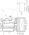
- the vehicle air conditioner 1 of the present embodiment is different from the first embodiment in that an open / close door 60 that switches the air flow state between the inside of the air conditioning case 12 and the battery housing space 52a is added. .
- an open / close door 60 is disposed in the communication duct 30.
- the open / close door 60 is a permissible state that allows air to flow between the interior of the air conditioning case 12 and the battery housing space 52a, and a block that blocks air flow between the interior of the air conditioning case 12 and the battery housing space 52a. It functions as a switching mechanism that switches between states.
- the open / close door 60 is configured to be displaceable between an open position where the intermediate opening 122 of the air conditioning case 12 is opened and a closed position where the intermediate opening 122 is closed. More specifically, the open / close door 60 of the present embodiment is a cantilever door.
- the open / close door 60 is not limited to a cantilever door, and may be a butterfly door, a slide door, or the like.
- the open / close door 60 of the present embodiment is configured by an electric door that can be opened and closed in accordance with a control signal from the control device 100.
- the opening / closing door 60 is connected to the output side of the control device 100 so as to be controllable by the control device 100.
- Each control step of the mode switching process shown in FIG. 8 constitutes a function realizing unit that realizes various functions executed by the control device 100.
- control device 100 reads the sensor signals of the various sensors 101 to 104 and the operation signals of the operation unit 110 in step S10. Subsequently, in step S20, control device 100 determines whether or not the battery temperature detected by battery temperature sensor 104 is equal to or lower than the appropriate upper limit temperature.
- step S20 when it is determined that the battery temperature is equal to or lower than the appropriate upper limit temperature, it is considered that cooling of the battery 51 is unnecessary. decide.
- the control device 100 stops the operation of the battery blower 56 in the indoor air conditioning mode, and controls the indoor blower 18 to the operating state in a state where the opening / closing door 60 is displaced to the closed position of the intermediate opening 122.
- the control apparatus 100 controls the action
- control device 100 controls the indoor blower 18 to the operating state while the operation of the battery blower 56 is stopped, so that an air flow toward the vehicle interior is generated inside the air-conditioning case 12. To do.
- the airflow introduced from the outside air introduction portion or the inside air introduction portion flows into the evaporator 16 via the air filter 14 as indicated by an arrow AFE in FIG. 9. .
- the airflow is cooled to a predetermined temperature by the evaporator 16 and then sucked into the indoor blower 18 from the air suction portion 151 as indicated by an arrow AFS in FIG.
- the air in the battery housing space 52a may flow into the indoor blower 18 via the communication duct 30. Since the air in the battery housing space 52a is sucked into the indoor blower 18, the temperature of the air cooled by the evaporator 16 is increased, so there is a concern that the air conditioning performance in the vehicle compartment is deteriorated.
- the vehicle air conditioner 1 of this embodiment displaces the opening / closing door 60 to the closed position of the intermediate opening 122 in the indoor air conditioning mode, the air in the battery housing space 52a is sucked into the indoor blower 18. It will not be.
- the air sucked into the indoor blower 18 is blown out radially from the inside of the fan 181 as indicated by an arrow AFD in FIG.
- the airflow passes through a heater core or a cold air bypass passage (not shown) and is then blown out into the vehicle compartment through one of the openings.
- step S20 determines whether the battery temperature exceeds the appropriate upper limit temperature. If it is determined as a result of the determination process in step S20 that the battery temperature exceeds the appropriate upper limit temperature, it is considered that the battery 51 needs to be cooled. Decide on cooling mode.
- the control device 100 controls both the indoor blower 18 and the battery blower 56 to the operating state with the open / close door 60 being displaced to the open position of the intermediate opening 122 in the battery cooling mode.
- the control apparatus 100 controls the action
- both the indoor fan 18 and the battery fan 56 are controlled to be in an operating state by the control device 100, so that the air flow toward the vehicle interior and the battery accommodating space 52 a are entered into the air conditioning case 12. Airflow is generated.
- the airflow introduced from the outside air introduction portion or the inside air introduction portion flows into the evaporator 16 via the air filter 14, as indicated by an arrow AFE in FIG.
- the evaporator 16 is cooled to a predetermined temperature.
- the air cooled by the evaporator 16 is sucked into the indoor blower 18 from the air suction portion 151 as indicated by an arrow AFS in FIG.
- the air sucked into the indoor blower 18 is blown out from the inside of the fan 181 toward the outside in the radial direction, as indicated by an arrow AFD in FIG.
- the airflow passes through a heater core or a cold air bypass passage (not shown) and is then blown out into the vehicle compartment through one of the openings.
- the opening / closing door 60 is displaced to the open position of the intermediate opening 122, the air cooled by the evaporator 16 passes through the communication duct 30 as shown by an arrow AFB1 in FIG. It is sucked into the battery blower 56 in the battery housing space 52a.
- the air sucked into the battery blower 56 is blown out to the battery 51 located on the downstream side of the air flow of the battery blower 56 as indicated by an arrow AFB2 in FIG. Thereby, the battery 51 is cooled. Then, the air that has absorbed heat from the battery 51 in the battery housing space 52a is discharged to the outside of the vehicle through the exhaust duct 54 as indicated by an arrow AFB3 in FIG.
- the vehicle air conditioner 1 of this embodiment has the same basic configuration as that of the first embodiment, the effects described in the first embodiment can be obtained in the same manner as in the first embodiment.
- the vehicle air conditioner 1 switches between an allowable state in which air is allowed to flow between the inside of the air conditioning case 12 and the battery housing space 52a and a cut-off state in which the air is blocked.
- An opening / closing door 60 is provided as a mechanism.
- the application object of the opening / closing door 60 is not limited to 1st Embodiment.
- the open / close door 60 can be applied to the vehicle air conditioner 1 described in the second embodiment or the third embodiment.
- the configuration in which the intermediate opening 122 is opened and closed by the opening and closing door 60 is illustrated, but the present invention is not limited to this.
- the open / close door 60 may be configured to open and close the air suction port 521 of the battery case 52.
- the opening / closing door 60 is, for example, a mechanical door configured to be displaced to a closed position when the battery blower 56 is stopped and to be moved to an open position when the battery blower 56 is operating. It may be configured.
- the indoor air conditioning unit 10 may be configured such that both the evaporator 16 and the heater core are disposed in the downstream space 132 of the ventilation path 13.
- the indoor air conditioning unit 10 may be configured such that both the evaporator 16 and the heater core are disposed in the upstream space 131 of the ventilation path 13, for example.
- the battery blower 56 is disposed on the upstream side of the air flow of the battery 51 or on the downstream side of the air flow of the battery 51 has been described.
- the battery blower 56 may be configured to be integrally attached to the battery 51 so as to be in the same position with respect to the air flow.
- the cooling heat exchanger that cools the air is not limited to the evaporator 16, and may be constituted by, for example, a heat exchanger in which cold water flows.
- the vehicle air conditioner guides the air flowing through the inside of the air conditioning case to the battery housing space via the communication duct.
- a battery blower is arranged.
- the communication duct is connected to the site
- the vehicle air conditioner includes a cooling heat exchanger that cools the air flowing inside the air conditioning case.
- the cooling heat exchanger is disposed on the upstream side of the air flow from the indoor blower.
- the communication duct is connected to a portion located on the downstream side of the air flow of the cooling heat exchanger in the air conditioning case and on the upstream side of the air flow of the indoor fan.
- the communication duct is connected between the cooling heat exchanger and the indoor fan in the air conditioning case, the cool air cooled by the cooling heat exchanger by the battery fan can be introduced into the battery housing space. it can. According to this, the battery can be sufficiently cooled by the cold air cooled by the cooling heat exchanger.
- the battery blower is disposed on the downstream side of the battery air flow in the battery accommodating space. According to this, since it is possible to prevent the temperature of the air supplied to the battery from rising due to the heat generated when the battery blower is operated, the battery can be efficiently cooled.
- an outside air ventilation path through which vehicle exterior air flows and an interior air ventilation path through which vehicle interior air flows are set inside the air conditioning case.
- the communication duct is connected to a portion that forms an outside air ventilation path in the air conditioning case so that the air outside the passenger compartment is introduced into the battery housing space.
- the vehicle exterior air which tends to be lower in humidity than the vehicle interior air, is introduced into the battery housing space, it is possible to suppress the occurrence of condensation on the battery when the battery is cooled.
- the outside air of the passenger compartment is introduced into the battery housing space at a temperature lower than that of the air in the passenger compartment, so that the battery can be efficiently cooled.
- the vehicle air conditioner includes an allowable state that allows air to flow between the inside of the air conditioning case and the battery housing space, and A switching mechanism for switching to a shut-off state that shuts off air flow is provided.
- the switching mechanism is configured to switch to an allowable state when the battery blower is operating and to switch to a shut-off state when the battery blower is stopped.
Landscapes
- Engineering & Computer Science (AREA)
- Mechanical Engineering (AREA)
- Physics & Mathematics (AREA)
- Thermal Sciences (AREA)
- Chemical & Material Sciences (AREA)
- Combustion & Propulsion (AREA)
- Transportation (AREA)
- Air-Conditioning For Vehicles (AREA)
- Secondary Cells (AREA)
- Cooling, Air Intake And Gas Exhaust, And Fuel Tank Arrangements In Propulsion Units (AREA)
- Arrangement Or Mounting Of Propulsion Units For Vehicles (AREA)
Priority Applications (1)
| Application Number | Priority Date | Filing Date | Title |
|---|---|---|---|
| EP17894735.4A EP3578396A4 (en) | 2017-02-02 | 2017-12-27 | VEHICLE AIR CONDITIONING |
Applications Claiming Priority (2)
| Application Number | Priority Date | Filing Date | Title |
|---|---|---|---|
| JP2017-017723 | 2017-02-02 | ||
| JP2017017723A JP6658584B2 (ja) | 2017-02-02 | 2017-02-02 | 車両用空調装置 |
Publications (1)
| Publication Number | Publication Date |
|---|---|
| WO2018142826A1 true WO2018142826A1 (ja) | 2018-08-09 |
Family
ID=63039513
Family Applications (1)
| Application Number | Title | Priority Date | Filing Date |
|---|---|---|---|
| PCT/JP2017/047108 Ceased WO2018142826A1 (ja) | 2017-02-02 | 2017-12-27 | 車両用空調装置 |
Country Status (3)
| Country | Link |
|---|---|
| EP (1) | EP3578396A4 (https=) |
| JP (1) | JP6658584B2 (https=) |
| WO (1) | WO2018142826A1 (https=) |
Families Citing this family (1)
| Publication number | Priority date | Publication date | Assignee | Title |
|---|---|---|---|---|
| JP2024108037A (ja) * | 2023-01-30 | 2024-08-09 | トヨタ自動車株式会社 | 電気自動車用空調システム |
Citations (6)
| Publication number | Priority date | Publication date | Assignee | Title |
|---|---|---|---|---|
| JPS4827391Y1 (https=) * | 1968-05-21 | 1973-08-13 | ||
| JP2006143183A (ja) * | 2004-10-18 | 2006-06-08 | Denso Corp | 車両用バッテリ冷却装置 |
| JP2008068740A (ja) * | 2006-09-14 | 2008-03-27 | Toyota Motor Corp | 空調システムおよび空調方法 |
| JP2008222041A (ja) | 2007-03-13 | 2008-09-25 | Mazda Motor Corp | 自動車のバッテリ冷却装置 |
| JP2013544700A (ja) * | 2010-10-29 | 2013-12-19 | ヴァレオ、オートモーティブ、エアー、コンディショニング、フーペイ、カンパニー、リミテッド | 電動車両またはハイブリッド電動車両の暖房、換気、および空調システム |
| JP2015003617A (ja) * | 2013-06-20 | 2015-01-08 | 三菱自動車工業株式会社 | 空調システム |
Family Cites Families (5)
| Publication number | Priority date | Publication date | Assignee | Title |
|---|---|---|---|---|
| JPH0698887B2 (ja) * | 1985-12-27 | 1994-12-07 | 日本電装株式会社 | 車両用空気調和装置 |
| DE102005049200A1 (de) * | 2004-10-18 | 2006-05-11 | Denso Corp., Kariya | Batteriekühlvorrichtung zur Fahrzeugnutzung |
| JP4466595B2 (ja) * | 2006-03-28 | 2010-05-26 | トヨタ自動車株式会社 | 冷却システムおよびこれを搭載する自動車並びに冷却システムの制御方法 |
| JP4327823B2 (ja) * | 2006-06-15 | 2009-09-09 | トヨタ自動車株式会社 | 冷却システムおよびこれを搭載する自動車並びに冷却システムの制御方法 |
| US10744901B2 (en) * | 2012-06-13 | 2020-08-18 | Ford Global Technologies, Llc | Cooling system having active cabin venting for a vehicle battery |
-
2017
- 2017-02-02 JP JP2017017723A patent/JP6658584B2/ja not_active Expired - Fee Related
- 2017-12-27 WO PCT/JP2017/047108 patent/WO2018142826A1/ja not_active Ceased
- 2017-12-27 EP EP17894735.4A patent/EP3578396A4/en not_active Withdrawn
Patent Citations (6)
| Publication number | Priority date | Publication date | Assignee | Title |
|---|---|---|---|---|
| JPS4827391Y1 (https=) * | 1968-05-21 | 1973-08-13 | ||
| JP2006143183A (ja) * | 2004-10-18 | 2006-06-08 | Denso Corp | 車両用バッテリ冷却装置 |
| JP2008068740A (ja) * | 2006-09-14 | 2008-03-27 | Toyota Motor Corp | 空調システムおよび空調方法 |
| JP2008222041A (ja) | 2007-03-13 | 2008-09-25 | Mazda Motor Corp | 自動車のバッテリ冷却装置 |
| JP2013544700A (ja) * | 2010-10-29 | 2013-12-19 | ヴァレオ、オートモーティブ、エアー、コンディショニング、フーペイ、カンパニー、リミテッド | 電動車両またはハイブリッド電動車両の暖房、換気、および空調システム |
| JP2015003617A (ja) * | 2013-06-20 | 2015-01-08 | 三菱自動車工業株式会社 | 空調システム |
Non-Patent Citations (1)
| Title |
|---|
| See also references of EP3578396A4 * |
Also Published As
| Publication number | Publication date |
|---|---|
| JP6658584B2 (ja) | 2020-03-04 |
| EP3578396A1 (en) | 2019-12-11 |
| JP2018122783A (ja) | 2018-08-09 |
| EP3578396A4 (en) | 2020-02-12 |
Similar Documents
| Publication | Publication Date | Title |
|---|---|---|
| CN105307880B (zh) | 车辆用空调装置 | |
| JP6332558B2 (ja) | 車両用空調装置 | |
| JP3309779B2 (ja) | 車両用空調装置 | |
| CN109153308B (zh) | 车辆用空调单元 | |
| US11254187B2 (en) | Vehicular air conditioner | |
| US20170050493A1 (en) | Air conditioner for vehicle | |
| WO2015008434A1 (ja) | 車両用空調装置 | |
| US20190111768A1 (en) | Air conditioning apparatus for vehicle | |
| JP2012236495A (ja) | 車両用空調装置 | |
| JP5895788B2 (ja) | 車両用空調装置 | |
| JP2016064695A (ja) | 車両用空調装置 | |
| US10780761B2 (en) | Inside-outside air switching unit | |
| JP3978826B2 (ja) | 車両用空調装置 | |
| JP5626094B2 (ja) | 車両用空調装置 | |
| JP5626095B2 (ja) | 車両用空調装置 | |
| US20040231834A1 (en) | Vehicle air conditioner | |
| JPH11115462A (ja) | 車両用空調装置 | |
| JP6658584B2 (ja) | 車両用空調装置 | |
| JP5494595B2 (ja) | 車両用空調装置 | |
| WO2013128791A1 (ja) | 温調装置 | |
| JP7556337B2 (ja) | 冷却システム | |
| US11498390B2 (en) | Vehicular air conditioner | |
| JP5476888B2 (ja) | 車両用空調装置 | |
| JPWO2018047463A1 (ja) | 車両用空調装置 | |
| JP2009279946A (ja) | 車両用空調装置 |
Legal Events
| Date | Code | Title | Description |
|---|---|---|---|
| 121 | Ep: the epo has been informed by wipo that ep was designated in this application |
Ref document number: 17894735 Country of ref document: EP Kind code of ref document: A1 |
|
| NENP | Non-entry into the national phase |
Ref country code: DE |
|
| ENP | Entry into the national phase |
Ref document number: 2017894735 Country of ref document: EP Effective date: 20190902 |