WO2018142796A1 - ヒートポンプ装置 - Google Patents
ヒートポンプ装置 Download PDFInfo
- Publication number
- WO2018142796A1 WO2018142796A1 PCT/JP2017/046011 JP2017046011W WO2018142796A1 WO 2018142796 A1 WO2018142796 A1 WO 2018142796A1 JP 2017046011 W JP2017046011 W JP 2017046011W WO 2018142796 A1 WO2018142796 A1 WO 2018142796A1
- Authority
- WO
- WIPO (PCT)
- Prior art keywords
- refrigerant
- radiator
- heat
- heat medium
- compressor
- Prior art date
- Legal status (The legal status is an assumption and is not a legal conclusion. Google has not performed a legal analysis and makes no representation as to the accuracy of the status listed.)
- Ceased
Links
Images


Classifications
-
- F—MECHANICAL ENGINEERING; LIGHTING; HEATING; WEAPONS; BLASTING
- F24—HEATING; RANGES; VENTILATING
- F24D—DOMESTIC- OR SPACE-HEATING SYSTEMS, e.g. CENTRAL HEATING SYSTEMS; DOMESTIC HOT-WATER SUPPLY SYSTEMS; ELEMENTS OR COMPONENTS THEREFOR
- F24D3/00—Hot-water central heating systems
- F24D3/18—Hot-water central heating systems using heat pumps
-
- F—MECHANICAL ENGINEERING; LIGHTING; HEATING; WEAPONS; BLASTING
- F24—HEATING; RANGES; VENTILATING
- F24H—FLUID HEATERS, e.g. WATER OR AIR HEATERS, HAVING HEAT-GENERATING MEANS, e.g. HEAT PUMPS, IN GENERAL
- F24H4/00—Fluid heaters characterised by the use of heat pumps
- F24H4/02—Water heaters
-
- F—MECHANICAL ENGINEERING; LIGHTING; HEATING; WEAPONS; BLASTING
- F25—REFRIGERATION OR COOLING; COMBINED HEATING AND REFRIGERATION SYSTEMS; HEAT PUMP SYSTEMS; MANUFACTURE OR STORAGE OF ICE; LIQUEFACTION SOLIDIFICATION OF GASES
- F25B—REFRIGERATION MACHINES, PLANTS OR SYSTEMS; COMBINED HEATING AND REFRIGERATION SYSTEMS; HEAT PUMP SYSTEMS
- F25B1/00—Compression machines, plants or systems with non-reversible cycle
- F25B1/10—Compression machines, plants or systems with non-reversible cycle with multi-stage compression
-
- F—MECHANICAL ENGINEERING; LIGHTING; HEATING; WEAPONS; BLASTING
- F25—REFRIGERATION OR COOLING; COMBINED HEATING AND REFRIGERATION SYSTEMS; HEAT PUMP SYSTEMS; MANUFACTURE OR STORAGE OF ICE; LIQUEFACTION SOLIDIFICATION OF GASES
- F25B—REFRIGERATION MACHINES, PLANTS OR SYSTEMS; COMBINED HEATING AND REFRIGERATION SYSTEMS; HEAT PUMP SYSTEMS
- F25B39/00—Evaporators; Condensers
- F25B39/04—Condensers
-
- F—MECHANICAL ENGINEERING; LIGHTING; HEATING; WEAPONS; BLASTING
- F25—REFRIGERATION OR COOLING; COMBINED HEATING AND REFRIGERATION SYSTEMS; HEAT PUMP SYSTEMS; MANUFACTURE OR STORAGE OF ICE; LIQUEFACTION SOLIDIFICATION OF GASES
- F25B—REFRIGERATION MACHINES, PLANTS OR SYSTEMS; COMBINED HEATING AND REFRIGERATION SYSTEMS; HEAT PUMP SYSTEMS
- F25B6/00—Compression machines, plants or systems, with several condenser circuits
- F25B6/04—Compression machines, plants or systems, with several condenser circuits arranged in series
Definitions
- the present disclosure relates to a heat pump device.
- the heat pump device described in Patent Document 1 heats hot water as a heat medium to a medium temperature and a high temperature using a supercritical cycle, stores the medium temperature hot water in a heat storage tank for medium temperature, and stores the hot water in a high temperature heat storage tank. It stores heat.
- This heat pump device takes out hot water from each heat storage tank according to the amount of hot water required for the purpose of use.
- the heat pump device described in Patent Document 1 does not always store the amount of hot water in an optimal balance between the heat storage tank for medium temperature and the heat storage tank for high temperature with respect to the amount of hot water required for the purpose of use. . Therefore, if the amount of hot water in one of the intermediate temperature heat storage tank and the high temperature heat storage tank is excessive, the energy used to generate the hot water is wasted.
- the heat pump device heats the heat medium flowing through each of the two heated circuits using the supercritical cycle
- the heat medium heated to a high temperature is called the first heat medium.
- the heat medium heated to an intermediate temperature will be referred to as the second heat medium.
- the heat pump device simultaneously heats the first heat medium and the second heat medium, it is required to control the heating amount of the first heat medium and the heating amount of the second heat medium to an appropriate ratio.
- the heat pump apparatus When the heat pump device heats the first heat medium and the second heat medium at the same time, if the ability to heat one of the first heat medium and the second heat medium is reduced, the other heat medium is heated.
- Ability increases.
- the heat pump apparatus cannot lower the temperature of hot water as a heat medium heated by the supercritical cycle below a certain temperature in order to prevent a decrease in hot water stored in the heat storage tank. Therefore, in the heat pump device that heats the first heat medium and the second heat medium at the same time, there is a restriction on a decrease in the ability to heat the first heat medium, and thus there is a limit to an increase in the ability to heat the second heat medium. .
- This disclosure aims to provide a heat pump device capable of increasing the heating capacity of the first heat medium and the second heat medium.
- a heat pump device that heats a first heat medium and a second heat medium, A first compressor for compressing the refrigerant; A second compressor that compresses the refrigerant discharged from the first compressor and raises the pressure of the refrigerant to a critical pressure or higher; A first radiator, a second radiator and a third radiator through which the refrigerant discharged from the second compressor flows, A first decompressor for decompressing the refrigerant flowing downstream of the third radiator; An evaporator that exchanges heat between the refrigerant decompressed by the first decompressor and the outside air, and flows out the refrigerant that has absorbed heat from the outside air toward the suction port of the first compressor; A first refrigerant path connecting the first compressor, the second compressor, the first radiator, the second radiator, the third radiator, the first decompressor, and the evaporator; The first heat medium is configured to flow from the third radiator to the first radiator in order, and the first heat medium is heated by
- a first heated side circuit A second heated side circuit configured such that the second heat medium flows to the second radiator, and the second heat medium is heated by heat exchange between the refrigerant flowing through the second radiator and the second heat medium;
- a refrigerant branch provided between the second radiator and the third radiator in the first refrigerant passage;
- a refrigerant merging portion provided between the first compressor and the second compressor in the first refrigerant passage;
- a second pressure reducer for depressurizing the refrigerant flowing through the second refrigerant passage;
- Internal heat exchange for exchanging heat between the refrigerant flowing between the refrigerant branch portion and the third radiator in the first refrigerant passage and the refrigerant flowing between the second decompressor and the refrigerant junction portion in the second refrigerant passage.
- the heat pump device is configured such that the first heat medium is heated by the third radiator and the first radiator, and the second heat medium is heated by the second radiator.
- the first refrigerant passage flows from the outlet of the second compressor to the first decompressor via the first radiator, the second radiator, the internal heat exchanger, and the third radiator.
- the pressure of the refrigerant hereinafter referred to as the high-pressure side refrigerant pressure
- the ability to heat the first heat medium to a high temperature can be relatively decreased, and the ability to heat the second heat medium to a medium temperature can be relatively increased. Is possible.
- by increasing the high-pressure side refrigerant pressure it is possible to relatively increase the ability to heat the first heat medium to a high temperature and to relatively reduce the ability to heat the second heat medium to an intermediate temperature. .
- the heat pump apparatus has a restriction that the ability to heat the first heat medium to a high temperature cannot be reduced below a certain ability. Therefore, it is difficult to increase the ability to heat the second heat medium to an intermediate temperature from a certain ability. Therefore, this heat pump device increases the flow rate of the refrigerant flowing through the first radiator and the second radiator by an injection circuit including the second refrigerant passage, the second pressure reducer, and the internal heat exchanger, so that the first heat The ability to heat the medium and the second heat medium is increased.
- this heat pump device uses an internal heat exchanger to exchange heat between the refrigerant flowing upstream of the third radiator in the first refrigerant passage and the refrigerant decompressed by the second decompressor in the second refrigerant passage. I am letting.
- the refrigerant flowing upstream from the third radiator in the first refrigerant passage has a higher temperature than the refrigerant flowing downstream from the third radiator, the refrigerant flowing through the second refrigerant passage in the internal heat exchanger is It is possible to obtain a higher endotherm. Therefore, it is possible to suppress a decrease in the enthalpy of the refrigerant flowing into the second compressor and increase the ability to heat the first heat medium and the second heat medium. Therefore, this heat pump device appropriately controls the ability to heat the first heat medium to a high temperature and the ability to heat the second heat medium to a medium temperature, and heats the first heat medium and the second heat medium with a good balance. can do.
- the heat pump device heats the first heat medium and the second heat medium, A first compressor for compressing the refrigerant; A second compressor that compresses the refrigerant discharged from the first compressor and raises the pressure of the refrigerant to a critical pressure or higher; A first radiator, a second radiator and a third radiator through which the refrigerant discharged from the second compressor flows, A first decompressor for decompressing the refrigerant flowing downstream of the third radiator; An evaporator that exchanges heat between the refrigerant decompressed by the first decompressor and the outside air, and flows out the refrigerant that has absorbed heat from the outside air toward the suction port of the first compressor; A first refrigerant path connecting the first compressor, the second compressor, the first radiator, the second radiator, the third radiator, the first decompressor, and the evaporator; A refrigerant branch provided between the second radiator and the third radiator in the first refrigerant passage; A refrigerant merging portion provided between the
- An exchange A tank for storing the first heat medium;
- the first heat medium flowing out of the tank is configured to flow from the third radiator to the first radiator in order, and the first heat medium is exchanged by heat exchange between the third radiator and the refrigerant flowing through the first radiator and the first heat medium.
- a first heated side circuit in which the medium is heated A second heated side circuit configured such that the second heat medium flows to the second radiator, and the second heat medium is heated by heat exchange between the refrigerant flowing through the second radiator and the second heat medium;
- a bypass passage configured such that the first heat medium flowing out of the tank of the first heated side circuit bypasses the third radiator and flows to the first radiator;
- a flow rate adjusting unit that adjusts a ratio between a flow rate of the first heat medium flowing from the tank to the bypass passage in the first heated side circuit and a flow rate of the first heat medium flowing from the tank to the third radiator;
- the heat pump device is similar to the heat pump device according to one aspect, by the injection circuit including the second refrigerant passage, the second pressure reducer, and the internal heat exchanger, the first heat medium and the second heat pump device.
- the ability to heat the heat medium is increased.
- the injection circuit when the injection circuit is installed in the heat pump device, the refrigerant flowing from the first compressor to the second compressor and the refrigerant flowing from the second refrigerant passage to the second compressor are mixed together, There exists a problem that the enthalpy of the refrigerant
- a bypass passage is provided in the first heated side circuit, and the flow rate adjustment unit causes the flow rate of the first heat medium flowing from the tank to the bypass passage, and the first flow from the tank to the third radiator. It is set as the structure which can adjust the flow volume of 1 heat medium. Thereby, if necessary, the flow rate ratio of the first heat medium flowing from the tank to the bypass passage is increased, and the flow rate ratio of the first heat medium flowing from the tank to the third radiator is decreased, whereby the internal heat exchanger.
- the enthalpy of the refrigerant flowing through the first refrigerant passage can be increased.
- this heat pump device appropriately controls the ability to heat the first heat medium to a high temperature and the ability to heat the second heat medium to a medium temperature, and heats the first heat medium and the second heat medium with a good balance. can do.
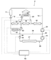
- the configuration of the heat pump device of the first embodiment is shown in FIG.
- the heat pump apparatus 1 includes a first heated side circuit 10, a second heated side circuit 20, a supercritical cycle 30, a control unit 50, and the like.
- the heat pump device 1 circulates the first heat medium circulating in the first heated side circuit 10 and the second heated side circuit 20 by a supercritical cycle 30 that performs heat transport using a refrigerant in a supercritical state.
- the second heat medium is heated simultaneously. For example, hot water or antifreeze is used as the first heat medium and the second heat medium.
- a first heat medium is stored in a tank 11 provided in the first heated side circuit 10.
- the first heat medium having a higher temperature is stored in the upper layer part
- the first heat medium having a lower temperature is stored in the lower layer part.
- the first heated circuit 10 is provided with a first circulation pump 12 for circulating the first heat medium.
- the first heat medium taken out from the bottom of the tank 11 by the drive of the first circulation pump 12 circulates through the first heated circuit 10.
- the first heat medium is heated by the third radiator 35 and the first radiator 33 included in the supercritical cycle 30 and is returned from the upper part of the tank 11 into the tank 11.
- the first heat medium stored in the tank 11 is used, for example, for hot water supply.
- the second heated side circuit 20 is also provided with a second circulation pump 21 for circulating the second heat medium.
- the second heat medium circulating in the second heated side circuit 20 is heated by the second radiator 34 provided in the supercritical cycle 30.
- the heated second heat medium is used for, for example, a heating facility 22 in a house.
- a heating facility 22 it is possible to employ floor heating in which a flow path through which the second heat medium flows is provided on the floor of a house.
- a facility that blows air-conditioned air heated by a heat exchanger through which the second heat medium flows into the room through a duct may be employed.
- the supercritical cycle 30 includes a plurality of compressors 31, 32, a plurality of radiators 33, 34, 35, a first decompressor 36, an evaporator 37, a first refrigerant passage 38, a second refrigerant passage 39, and a second decompression.
- the apparatus 40, the internal heat exchanger 41, etc. are connected by piping.
- CO 2 is used as the refrigerant circulating in the supercritical cycle 30.
- a passage connecting the plurality of compressors 31 and 32, the plurality of radiators 33, 34 and 35, the internal heat exchanger 41, the first decompressor 36 and the evaporator 37 is referred to as a first refrigerant passage 38. I will call it.
- a refrigerant branch portion 42 is provided between the second radiator 34 and the third radiator 35.
- a refrigerant junction 43 is provided between the first compressor 31 and the second compressor 32.
- a passage connecting the refrigerant branching portion 42 and the refrigerant merging portion 43 separately from the first refrigerant passage 38 is referred to as a second refrigerant passage 39 or an injection circuit.
- Each component of the supercritical cycle 30 is driven and controlled by the control unit 50.
- signal lines between the control unit 50 and each component are indicated by broken lines.
- a low-stage first compressor 31 and a high-stage second compressor 32 are connected in series.
- the first compressor 31 compresses the refrigerant sucked from the suction port and discharges it from the discharge port.
- the refrigerant discharged from the first compressor 31 is sucked into the suction port of the second compressor 32.
- the second compressor 32 further compresses the refrigerant discharged from the first compressor 31, raises the pressure of the refrigerant to a critical pressure or higher, and discharges it from the discharge port.
- the first compressor 31 and the second compressor 32 are both electric compressors, and the rotation speed is controlled by the control unit 50.
- the plurality of radiators 33, 34, and 35 are connected in series from the discharge port side of the second compressor 32 in the order of the first radiator 33, the second radiator 34, and the third radiator 35.
- An internal heat exchanger 41 is provided between the second radiator 34 and the third radiator 35. Therefore, the refrigerant discharged from the second compressor 32 flows in the order of the first radiator 33, the second radiator 34, the internal heat exchanger 41, and the third radiator 35.
- the first heated side circuit 10 described above is configured such that the first heat medium flowing out from the tank 11 flows in the order from the third radiator 35 to the first radiator 33. Therefore, in the 3rd radiator 35 and the 1st radiator 33, heat exchange with a refrigerant and the 1st heat carrier is performed, respectively, and it is radiated from the refrigerant to the 1st heat carrier. Thereby, the first heat medium is heated.
- the second heated side circuit 20 described above is configured such that the second heat medium flows to the second radiator 34.
- the second radiator 34 heat exchange between the refrigerant and the second heat medium is performed, and heat is radiated from the refrigerant to the second heat medium. Thereby, the second heat medium is heated.
- the enthalpy of the refrigerant flowing through the first radiator 33 is the highest.
- the enthalpy of the refrigerant flowing through the second radiator 34 is lower than the enthalpy of the refrigerant flowing through the first radiator 33.
- the enthalpy of the refrigerant flowing through the third radiator 35 is lower than the enthalpy of the refrigerant flowing through the second radiator 34.
- a first decompressor 36 is provided on the downstream side of the third radiator 35.
- the first decompressor 36 is an expansion valve for decompressing the refrigerant flowing on the downstream side of the third radiator 35.
- the first decompressor 36 is configured such that the opening degree of the flow path in the first decompressor 36 can be adjusted by a signal transmitted from the control unit 50.
- the high-pressure side refrigerant pressure can be changed by adjusting the opening degree of the flow path of the first pressure reducer 36 and the opening degree of the flow path of the second pressure reducer 40 described later.
- the first refrigerant passage 38 is connected to the suction port of the first compressor 31 via the evaporator 37 from the first pressure reducer 36. It is possible to change the pressure of the flowing refrigerant.
- An evaporator 37 is provided in the first refrigerant passage 38 on the downstream side of the first decompressor 36.
- the pressure of the refrigerant decompressed by the first decompressor 36 is lower than the critical pressure. Therefore, the refrigerant flowing in the first refrigerant passage 38 on the downstream side of the first pressure reducer 36 enters the evaporator 37 in a gas-liquid two-phase state.
- heat is exchanged between the refrigerant in the gas-liquid two-phase state and the outside air. Thereby, a refrigerant
- coolant absorbs heat from external air and an enthalpy becomes high.
- the refrigerant flowing out of the evaporator 37 is sucked into the suction port of the first compressor 31 provided on the downstream side of the evaporator 37.
- the refrigerant branching portion 42 is provided between the second radiator 34 and the third radiator 35 in the first refrigerant passage 38.
- the refrigerant branching portion 42 is provided between the second radiator 34 and the internal heat exchanger 41 in the first refrigerant passage 38.
- the refrigerant junction portion 43 is provided between the first compressor 31 and the second compressor 32 in the first refrigerant passage 38.
- the second refrigerant passage 39 is an injection circuit that connects the refrigerant branch portion 42 and the refrigerant junction portion 43.
- the second refrigerant passage 39 is provided with a second decompressor 40 that decompresses the refrigerant flowing through the second refrigerant passage 39.
- the second decompressor 40 is an expansion valve for decompressing the refrigerant that has flowed out of the second radiator 34 and then branched into the second refrigerant passage 39 via the refrigerant branch portion 42.
- the second decompressor 40 is also configured to be able to adjust the opening degree of the flow path in the second decompressor 40 by a signal transmitted from the control unit 50. By adjusting the opening degree of the flow path of the second pressure reducer 40, it is possible to change the pressure of the refrigerant flowing between the second pressure reducer 40 and the refrigerant joining portion 43 in the second refrigerant passage 39.
- an internal heat exchanger 41 is provided on the downstream side of the second decompressor 40.
- the pressure of the refrigerant decompressed by the second decompressor 40 becomes lower than the critical pressure. Therefore, the refrigerant flowing in the second refrigerant passage 39 on the downstream side of the second decompressor 40 enters a gas-liquid two-phase state and flows into the internal heat exchanger 41.
- the refrigerant flowing between the refrigerant branch portion 42 and the third radiator 35 in the first refrigerant passage 38, the second decompressor 40 and the refrigerant junction portion 43 in the second refrigerant passage 39 Heat exchange with the refrigerant flowing between the two.
- the gas-liquid two-phase refrigerant flowing in the second refrigerant passage 39 in the internal heat exchanger 41 absorbs heat from the refrigerant flowing in the first refrigerant passage 38 in the internal heat exchanger 41, and the enthalpy is high.
- the refrigerant flowing out of the internal heat exchanger 41 in the second refrigerant passage 39 is mixed with the refrigerant discharged from the first compressor 31 through the refrigerant junction 43 and sucked into the second compressor 32.
- coolant flow volume which is compressed by the 2nd compressor 32 and flows through the 1st heat radiator 33 and the 2nd heat radiator 34 from the 2nd compressor 32 increases.
- the control unit 50 includes a microcomputer including memories such as a CPU, a ROM, and a RAM, and peripheral circuits thereof.
- the memory of the control unit 50 is composed of a non-transitional tangible storage medium.
- the control unit 50 receives signals from various sensors provided in the heat pump apparatus 1 and an operation request signal or a stop request signal from an operation / stop switch (not shown).
- the control unit 50 performs various calculations and processes based on the control program stored in the memory, and the first compressor 31, the second compressor 32, the first decompressor 36, and the second decompression connected to the output side.
- the operation of the container 40, the first circulation pump 12, the second circulation pump 21, and the like are controlled.
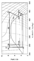
- FIG. 2 shows an example of the behavior of the refrigerant on the Mollier diagram.
- the points A1 to A11 shown in FIG. 2 show an example of the state of the refrigerant at each position of the supercritical cycle 30. Note that the positions of the points A1 to A11 are the rotational speeds of the first compressor 31 and the second compressor 32, the opening degrees of the flow paths of the first decompressor 36 and the second decompressor 40, the first heat medium and the first heat medium. 2. It varies depending on various conditions such as the flow rate and temperature of the heat medium and the outside air temperature.
- Point A 2 shows the state of the refrigerant on the suction side of the first compressor 31.
- Point A ⁇ b> 2 indicates the state of the refrigerant on the discharge side of the first compressor 31.
- Point A3 is a state in which the refrigerant flowing out of the internal heat exchanger 41 in the second refrigerant passage 39 is mixed with the refrigerant on the discharge side of the first compressor 31, that is, the refrigerant on the suction side of the second compressor 32.
- Point A4 indicates the state of the refrigerant on the discharge side of the second compressor 32, that is, the state of the refrigerant at the inlet of the first radiator 33.
- Point A5 indicates the state of the refrigerant at the inlet of the second radiator 34.
- Point A6 indicates the state of the refrigerant at the inlet of the internal heat exchanger 41 in the first refrigerant passage 38 and the state of the refrigerant at the inlet of the second decompressor 40.
- Point A ⁇ b> 7 indicates the state of the refrigerant at the inlet of the third radiator 35.
- Point A ⁇ b> 8 indicates the state of the refrigerant at the inlet of the first pressure reducer 36.
- Point A9 indicates the state of the refrigerant at the inlet of the evaporator 37.
- Point A ⁇ b> 10 indicates the state of the refrigerant at the inlet of the internal heat exchanger 41 in the second refrigerant passage 39.
- Point A ⁇ b> 11 indicates the state of the refrigerant at the outlet of the internal heat exchanger 41 in the second refrigerant passage 39.
- the refrigerant branching portion 42 where the refrigerant flows from the first refrigerant passage 38 to the second refrigerant passage 39 is connected to the second radiator 34 and the third radiator 35 in the first refrigerant passage 38.
- the internal heat exchanger 41 exchanges heat between the refrigerant flowing upstream of the third radiator 35 in the first refrigerant passage 38 and the refrigerant decompressed by the second decompressor 40 in the second refrigerant passage 39. It is the structure to do.
- the second refrigerant passage in the internal heat exchanger 41 Since the refrigerant flowing upstream from the third radiator 35 in the first refrigerant passage 38 has higher enthalpy than the refrigerant flowing downstream from the third radiator 35, the second refrigerant passage in the internal heat exchanger 41.
- the refrigerant flowing through 39 can obtain a larger endotherm. Therefore, a decrease in the enthalpy of the refrigerant flowing into the second compressor 32 is suppressed. Therefore, the supercritical cycle 30 can improve the ability to heat the first heat medium and the second heat medium.
- the configuration of the heat pump device 2 of the comparative example is shown in FIG.
- an internal heat exchanger 41 is provided between the third radiator 35 and the first pressure reducer 36. Therefore, the refrigerant discharged from the second compressor 32 flows through the first refrigerant circuit in the order of the first radiator 33, the second radiator 34, the third radiator 35, and the internal heat exchanger 41.
- FIG. 2 an example of the behavior of the refrigerant flowing through the supercritical cycle 30 of the heat pump device 2 of the comparative example is indicated by a broken line.
- the points B1 to B11 shown in FIG. 2 show an example of the state of the refrigerant at each position of the supercritical cycle 30.
- the positions of the points B1 to B11 are also the rotational speeds of the first compressor 31 and the second compressor 32, the opening degrees of the flow paths of the first decompressor 36 and the second decompressor 40, the first heat medium and the first heat medium. 2. It varies depending on various conditions such as the flow rate and temperature of the heat medium and the outside air temperature.
- Point B6 indicates the state of the refrigerant at the inlet of the third radiator 35 in the first refrigerant passage 38 and the state of the refrigerant at the inlet of the second decompressor 40.
- Point B7 indicates the state of the refrigerant at the inlet of the internal heat exchanger 41.
- the internal heat exchanger 41 causes the refrigerant flowing in the downstream side of the third radiator 35 in the first refrigerant passage 38 and the refrigerant decompressed by the second decompressor 40 in the second refrigerant passage 39 to each other. It is the structure which heat-exchanges.
- the refrigerant flowing downstream from the third radiator 35 in the first refrigerant passage 38 has a lower enthalpy than the refrigerant flowing upstream from the third radiator 35. Therefore, as shown by a point B11 in FIG. 2, the refrigerant flowing through the second refrigerant passage 39 in the internal heat exchanger 41 of the comparative example cannot obtain sufficient heat absorption. Therefore, as indicated by point B3, the enthalpy of the refrigerant sucked into the second compressor 32 of the comparative example is smaller than the enthalpy of the refrigerant in the state indicated by A3 in the first embodiment.
- the state of the refrigerant shown at the point B3 is in a state where the enthalpy is lower than the saturated vapor line SV and includes a liquid phase state. If the liquid refrigerant is sucked into the compressor, the compressor may break down. Therefore, in the comparative example, the flow rate of the refrigerant flowing out from the internal heat exchanger 41 in the second refrigerant passage 39 must be reduced. Therefore, in the configuration of the comparative example, it is difficult to increase the flow rate of the refrigerant flowing from the second compressor 32 through the first radiator 33 and the second radiator 34.
- the compression ratio of the refrigerant by the second compressor 32 is larger than the compression ratio of the refrigerant by the first compressor 31, so that the compression efficiency by the second compressor 32 is deteriorated.
- the enthalpy of the refrigerant discharged from the second compressor 32 of the comparative example indicated by point B4 is smaller than the enthalpy of the refrigerant discharged from the second compressor 32 of the first embodiment indicated by A4. Therefore, the ability to heat the first heat medium and the second heat medium in the supercritical cycle 30 of the comparative example is compared with the ability to heat the first heat medium and the second heat medium in the supercritical cycle 30 of the first embodiment. It is small.
- the heat pump device 1 can control the ability to heat the first heat medium to a high temperature and the ability to heat the second heat medium to a medium temperature by adjusting the high-pressure side refrigerant pressure. Specifically, when the high-pressure side refrigerant pressure is lowered, the temperature of the refrigerant discharged from the second compressor 32 and flowing into the first radiator 33 is lowered. Therefore, by reducing the high-pressure side refrigerant pressure, it is possible to relatively reduce the ability to heat the first heat medium to a high temperature and relatively increase the ability to heat the second heat medium to a medium temperature. .
- the amount of heat necessary for heating the second heat medium relative to the amount of heat necessary for heating the first heat medium is defined as a heating ratio.
- the heating ratio is reduced by increasing the high-pressure side refrigerant pressure.
- the heating ratio increases by lowering the high-pressure side refrigerant pressure.
- the heat pump device 1 has a restriction that the ability to heat the first heat medium to a high temperature cannot be reduced below a certain ability. For example, when the temperature of the first heat medium heated by the first heat radiator 33 is lower than the temperature of the first medium stored in the upper layer portion of the tank 11, the first stored in the upper layer portion of the tank 11. The temperature of the heat medium will decrease. Further, the temperature of the first medium stored in the tank 11 needs to be maintained at a temperature higher than a certain temperature in order to prevent propagation of various germs.
- the heating ratio is increased by lowering the high-pressure side refrigerant pressure, the ability to heat the second heat medium to a medium temperature relatively increases, while the ability to heat the first heat medium to a high temperature. Decreases relatively. For this reason, the high-pressure side refrigerant pressure can only be lowered within the range of restrictions for heating the first heat medium to a high temperature, and the heating ratio is increased to increase the heating capacity of the second heat medium. There will be a limit. Actually, when the first heat medium of the heat pump device 1 is used for hot water supply and the second heat medium is used for heating, there are many situations where a large heating capacity is required, so that the heating ratio cannot be made more than a certain level. It can be said that it is practically difficult.
- the heat pump device 1 is provided with an injection circuit.
- injection is performed, and the amount of refrigerant circulation for heating the first heat medium and the second heat medium is increased, thereby supporting high capacity. can do.
- the refrigerant flowing upstream from the third radiator 35 in the first refrigerant passage 38 and the second decompressor 40 in the second refrigerant passage 39 are decompressed. It is the structure which heat-exchanges with the made refrigerant
- the heat pump device 1 appropriately controls the ability to heat the first heat medium to a high temperature and the ability to heat the second heat medium to a medium temperature, and balances the first heat medium and the second heat medium. Can be heated.
- an internal heat exchanger 41 is provided between the third radiator 35 and the first decompressor 36.
- the first heated side circuit 10 is provided with a flow rate adjusting unit 13 and a bypass passage 14.
- the flow rate adjusting unit 13 is a three-way switching valve provided in the middle of a pipe connecting the tank 11 and the third radiator 35.
- a first circulation pump 12 is also provided in the pipe connecting the tank 11 and the third radiator 35.
- the flow rate adjusting unit 13 is provided on the downstream side of the first circulation pump 12.
- bypass passage 14 is connected to a three-way switching valve as the flow rate adjustment unit 13, and the other end is connected to a pipe 15 that connects the third radiator 35 and the first radiator 33.
- the bypass passage 14 is configured such that the first heat medium flowing out of the tank 11 bypasses the third radiator 35 and flows to the first radiator 33.
- the flow rate adjusting unit 13 described above includes the flow rate of the first heat medium flowing from the tank 11 to the bypass passage 14 in the first heated side circuit 10 and the flow rate of the first heat medium flowing from the tank 11 to the third radiator 35. It is possible to adjust the ratio.
- the operation of the flow rate adjusting unit 13 is controlled by the control unit 50.
- the solid line in FIG. 5 indicates that the first heat medium flows from the tank 11 to the bypass passage 14 and the first heat medium does not flow to the third radiator 35 by the flow rate adjusting unit 13.
- An example of the behavior of the refrigerant is shown.
- the third radiator 35 functions as a refrigerant passage in which almost no enthalpy of the refrigerant is taken away.
- the broken line in FIG. 5 indicates that the first heat medium flows into the third radiator 35 without flowing the first heated side circuit 10 from the tank 11 to the bypass passage 14 by the flow rate adjusting unit 13.
- An example of the behavior of the refrigerant in the state of The solid line in FIG. 6 is the same as that indicated by the broken line in FIG.
- the points C1 to C10 shown in FIG. 5 show an example of the state of the refrigerant at each position of the supercritical cycle 30.
- the positions of the points C1 to C11 are the rotation speeds of the first compressor 31 and the second compressor 32, the opening degrees of the flow paths of the first pressure reducer 36 and the second pressure reducer 40, the first heat medium, and the first heat medium. 2. It varies depending on various conditions such as the flow rate and temperature of the heat medium and the outside air temperature.
- Point C ⁇ b> 2 indicates the state of the refrigerant on the discharge side of the first compressor 31.
- Point C3 is a state in which the refrigerant flowing out of the internal heat exchanger 41 in the second refrigerant passage 39 and the refrigerant on the discharge side of the first compressor 31 are mixed, that is, the refrigerant on the suction side of the second compressor 32.
- Point C4 indicates the state of the refrigerant on the discharge side of the second compressor 32, that is, the state of the refrigerant at the inlet of the first radiator 33.
- Point C ⁇ b> 5 indicates the state of the refrigerant at the inlet of the second radiator 34.
- Point C6 indicates the state of the refrigerant at the inlet of the internal heat exchanger 41 in the first refrigerant passage 38 and the state of the refrigerant at the inlet of the second decompressor 40.
- Point C ⁇ b> 7 indicates the state of the refrigerant at the inlet of the first pressure reducer 36.
- a point C8 indicates the state of the refrigerant at the inlet of the evaporator 37.
- Point C ⁇ b> 9 indicates the state of the refrigerant at the inlet of the internal heat exchanger 41 in the second refrigerant passage 39.
- a point C ⁇ b> 10 indicates the state of the refrigerant at the outlet of the internal heat exchanger 41 in the second refrigerant passage 39.
- the solid line in FIG. 5 indicates that the first heat medium flows from the tank 11 to the bypass passage 14 through the first heated circuit 10 by the flow rate adjustment unit 13, and the first heat medium flows to the third radiator 35.
- An example of the behavior of the refrigerant in a state of not flowing is shown.
- the control unit 50 controls the flow rate adjustment unit 13 to increase the flow rate ratio of the first heat medium flowing from the tank 11 to the bypass passage 14 in the first heated side circuit 10, 3 It is preferable to reduce the flow rate ratio of the first heat medium flowing through the radiator 35. Thereby, the enthalpy of the refrigerant flowing through the first refrigerant passage 38 in the internal heat exchanger 41 is increased.
- the refrigerant flowing through the second refrigerant passage 39 in the internal heat exchanger 41 can obtain larger heat absorption. Therefore, since the fall of the enthalpy of the refrigerant
- Point D6 indicates the state of the refrigerant at the inlet of the third radiator 35 in the first refrigerant passage 38 and the state of the refrigerant at the inlet of the second decompressor 40.
- Point D ⁇ b> 7 indicates the state of the refrigerant at the inlet of the internal heat exchanger 41 in the first refrigerant passage 38.
- Point D ⁇ b> 8 indicates the state of the refrigerant at the inlet of the first pressure reducer 36.
- a point D9 indicates the state of the refrigerant at the inlet of the evaporator 37.
- a point D ⁇ b> 10 indicates the state of the refrigerant at the inlet of the internal heat exchanger 41 in the second refrigerant passage 39.
- Point D ⁇ b> 11 indicates the state of the refrigerant at the outlet of the internal heat exchanger 41 in the second refrigerant passage 39.
- FIG. 35 shows an example of the behavior of the refrigerant in a state where the first heat medium is flowing.
- the control unit 50 controls the flow rate adjusting unit 13 to reduce the flow rate ratio of the first heat medium flowing through the first heated side circuit 10 from the tank 11 to the bypass passage 14 and from the tank 11 to the first heating medium. 3 It is preferable to increase the flow rate ratio of the first heat medium flowing in the radiator 35. Thereby, the first heat medium flowing through the first heated circuit 10 can be heated by both the third radiator 35 and the first radiator 33. Therefore, the ability to heat the first heat medium can be increased.
- the flow rate adjusting unit provided in the first heated side circuit 10 is constituted by a first flow rate adjusting valve 16 and a second flow rate adjusting valve 17.
- the first flow rate adjustment valve 16 is provided in the bypass passage 14.
- the second flow rate adjusting valve 17 is provided in a passage connecting the branch point 18 on the upstream side of the bypass passage 14 and the inlet of the third radiator 35 in the first heated side circuit 10.
- the operations of the first flow rate adjustment valve 16 and the second flow rate adjustment valve 17 are controlled by the control unit 50.
- This 3rd Embodiment can also have the same operation effect as a 2nd embodiment.
- the heat pump device 1 includes the first radiator 33, the second radiator 34, and the third radiator 35.
- the heat pump device 1 may add another radiator in addition to the first radiator 33, the second radiator 34, and the third radiator 35.
- the other radiator may be arranged at any location between the second compressor 32 and the first decompressor 36 in the first refrigerant passage 38.
- the heat pump device 1 uses CO 2 as the refrigerant.
- CO 2 the refrigerant
- other embodiments not only CO 2 but also various refrigerants may be used.
- the heat pump device 1 uses hot water or antifreeze as a heat medium.
- a heat pump apparatus heats a 1st heat medium and a 2nd heat medium.
- the heat pump device includes a first compressor, a second compressor, a first radiator, a second radiator, a third radiator, a first decompressor, an evaporator, a first refrigerant passage, a first heated circuit, 2 A heated side circuit, a refrigerant branching part, a refrigerant merging part, a second refrigerant passage, a second decompressor, and an internal heat exchanger are provided.
- the first compressor compresses the refrigerant.
- the second compressor compresses the refrigerant discharged from the first compressor and raises the refrigerant pressure to a critical pressure or higher.
- the refrigerant discharged from the second compressor flows through the first radiator, the second radiator, and the third radiator in this order.
- the first decompressor decompresses the refrigerant flowing downstream from the third radiator.
- the evaporator exchanges heat between the refrigerant decompressed by the first decompressor and the outside air, and flows out the refrigerant that has absorbed heat from the outside air toward the suction port of the first compressor.
- the first refrigerant passage connects the first compressor, the second compressor, the first radiator, the second radiator, the internal heat exchanger, the third radiator, the first decompressor, and the evaporator.
- the first heated side circuit is configured such that the first heat medium flows in the order from the third radiator to the first radiator.
- the first heat medium is heated by heat exchange between the third heat radiator and the refrigerant flowing through the first heat radiator and the first heat medium.
- the second heated side circuit is configured such that the second heat medium flows to the second radiator.
- the second heat medium is heated by heat exchange between the refrigerant flowing through the second radiator and the second heat medium.
- the refrigerant branching portion is provided between the second radiator and the third radiator in the first refrigerant passage.
- the refrigerant junction is provided between the first compressor and the second compressor in the first refrigerant passage.
- the second refrigerant passage connects the refrigerant branch portion and the refrigerant junction portion.
- the second decompressor decompresses the refrigerant flowing through the second refrigerant passage.
- the internal heat exchanger includes a refrigerant that flows between the refrigerant branch portion and the third radiator in the first refrigerant passage, and a refrigerant that flows between the second decompressor and the refrigerant junction portion in the second refrigerant passage. Heat exchange.
- the heat pump device for heating the first heat medium and the second heat medium includes the first compressor, the second compressor, the first radiator, the second radiator, the third radiator, 1 decompressor, evaporator, first refrigerant passage, refrigerant branching portion, refrigerant junction, second refrigerant passage, second decompressor, internal heat exchanger, tank, first heated side circuit, second heated side circuit A bypass passage and a flow rate adjusting unit.
- the first compressor compresses the refrigerant.
- the second compressor compresses the refrigerant discharged from the first compressor and raises the refrigerant pressure to a critical pressure or higher.
- the refrigerant discharged from the second compressor flows through the first radiator, the second radiator, and the third radiator in this order.
- the first decompressor decompresses the refrigerant flowing downstream from the third radiator.
- the evaporator exchanges heat between the refrigerant decompressed by the first decompressor and the outside air, and flows out the refrigerant that has absorbed heat from the outside air toward the suction port of the first compressor.
- the first refrigerant passage connects the first compressor, the second compressor, the first radiator, the second radiator, the internal heat exchanger, the third radiator, the first decompressor, and the evaporator.
- the refrigerant branching portion is provided between the second radiator and the third radiator in the first refrigerant passage.
- the refrigerant junction is provided between the first compressor and the second compressor in the first refrigerant passage.
- the second refrigerant passage connects the refrigerant branch portion and the refrigerant junction portion.
- the second decompressor decompresses the refrigerant flowing through the second refrigerant passage.
- the internal heat exchanger includes a refrigerant that flows between the third radiator and the first decompressor in the first refrigerant passage, and a refrigerant that flows between the second decompressor and the refrigerant junction in the second refrigerant passage. Heat exchange.
- the tank stores the first heat medium.
- the first heated side circuit is configured such that the first heat medium flowing out of the tank flows from the third radiator to the first radiator.
- the first heat medium is heated by heat exchange between the third heat radiator and the refrigerant flowing through the first heat radiator and the first heat medium.
- the second heated side circuit is configured such that the second heat medium flows to the second radiator.
- the second heat medium is heated by heat exchange between the refrigerant flowing through the second radiator and the second heat medium.
- the bypass passage is configured such that the first heat medium flowing out of the tank in the first heated side circuit bypasses the third radiator and flows to the first radiator.
- the flow rate adjusting unit adjusts the ratio between the flow rate of the first heat medium flowing from the tank to the bypass passage in the first heated side circuit and the flow rate of the first heat medium flowing from the tank to the third radiator.
- the heat pump device includes a control unit.
- the control unit causes the first heat medium to flow from the tank to the bypass passage. Increase the flow rate.
- the control unit controls the flow rate adjusting unit so as to reduce the flow rate ratio of the first heat medium flowing from the tank to the third radiator.
- the control unit controls the flow rate adjusting unit to increase the flow rate ratio of the first heat medium flowing from the tank to the third radiator.
- the internal heat exchanger is controlled by the control of the control unit described above. Among them, the enthalpy of the refrigerant flowing through the first refrigerant passage is increased. Therefore, since the refrigerant flowing through the second refrigerant passage in the internal heat exchanger obtains a larger heat absorption, a decrease in the enthalpy of the refrigerant flowing into the second compressor is suppressed, and the ability to heat the second heat medium is increased. It is possible to make it.
- the first heat medium is controlled by the control of the control unit described above. Heating can be performed by both the third radiator and the first radiator. Therefore, it is possible to increase the ability to heat the first heat medium.
Landscapes
- Engineering & Computer Science (AREA)
- Physics & Mathematics (AREA)
- Mechanical Engineering (AREA)
- Thermal Sciences (AREA)
- General Engineering & Computer Science (AREA)
- Chemical & Material Sciences (AREA)
- Combustion & Propulsion (AREA)
- Heat-Pump Type And Storage Water Heaters (AREA)
- Steam Or Hot-Water Central Heating Systems (AREA)
Applications Claiming Priority (2)
| Application Number | Priority Date | Filing Date | Title |
|---|---|---|---|
| JP2017018674A JP2018124036A (ja) | 2017-02-03 | 2017-02-03 | ヒートポンプ装置 |
| JP2017-018674 | 2017-02-03 |
Publications (1)
| Publication Number | Publication Date |
|---|---|
| WO2018142796A1 true WO2018142796A1 (ja) | 2018-08-09 |
Family
ID=63039489
Family Applications (1)
| Application Number | Title | Priority Date | Filing Date |
|---|---|---|---|
| PCT/JP2017/046011 Ceased WO2018142796A1 (ja) | 2017-02-03 | 2017-12-21 | ヒートポンプ装置 |
Country Status (2)
| Country | Link |
|---|---|
| JP (1) | JP2018124036A (https=) |
| WO (1) | WO2018142796A1 (https=) |
Cited By (1)
| Publication number | Priority date | Publication date | Assignee | Title |
|---|---|---|---|---|
| EP3699513A1 (en) * | 2019-02-19 | 2020-08-26 | Panasonic Intellectual Property Management Co., Ltd. | Refrigeration apparatus |
Families Citing this family (1)
| Publication number | Priority date | Publication date | Assignee | Title |
|---|---|---|---|---|
| JP6680234B2 (ja) * | 2017-02-03 | 2020-04-15 | 株式会社デンソー | ヒートポンプ装置 |
Citations (3)
| Publication number | Priority date | Publication date | Assignee | Title |
|---|---|---|---|---|
| JP2010091135A (ja) * | 2008-10-03 | 2010-04-22 | Tokyo Electric Power Co Inc:The | 二段圧縮式給湯装置およびその起動制御方法 |
| JP2010164291A (ja) * | 2008-12-15 | 2010-07-29 | Denso Corp | エジェクタ式冷凍サイクル |
| WO2010103825A1 (ja) * | 2009-03-13 | 2010-09-16 | ダイキン工業株式会社 | ヒートポンプシステム |
-
2017
- 2017-02-03 JP JP2017018674A patent/JP2018124036A/ja active Pending
- 2017-12-21 WO PCT/JP2017/046011 patent/WO2018142796A1/ja not_active Ceased
Patent Citations (3)
| Publication number | Priority date | Publication date | Assignee | Title |
|---|---|---|---|---|
| JP2010091135A (ja) * | 2008-10-03 | 2010-04-22 | Tokyo Electric Power Co Inc:The | 二段圧縮式給湯装置およびその起動制御方法 |
| JP2010164291A (ja) * | 2008-12-15 | 2010-07-29 | Denso Corp | エジェクタ式冷凍サイクル |
| WO2010103825A1 (ja) * | 2009-03-13 | 2010-09-16 | ダイキン工業株式会社 | ヒートポンプシステム |
Cited By (1)
| Publication number | Priority date | Publication date | Assignee | Title |
|---|---|---|---|---|
| EP3699513A1 (en) * | 2019-02-19 | 2020-08-26 | Panasonic Intellectual Property Management Co., Ltd. | Refrigeration apparatus |
Also Published As
| Publication number | Publication date |
|---|---|
| JP2018124036A (ja) | 2018-08-09 |
Similar Documents
| Publication | Publication Date | Title |
|---|---|---|
| US20120000237A1 (en) | Heat pump system | |
| JP5181813B2 (ja) | 冷凍装置 | |
| JP6792057B2 (ja) | 冷凍サイクル装置 | |
| JP2006343017A (ja) | 冷凍装置 | |
| JP5205079B2 (ja) | ヒートポンプ式給湯暖房装置 | |
| JP6537733B2 (ja) | ヒートポンプ装置 | |
| CN111051793B (zh) | 空气调节装置 | |
| CN111133258B (zh) | 空调装置 | |
| CN102365510A (zh) | 空调热水供给复合系统 | |
| JP2016075402A (ja) | 空気調和機 | |
| JP2008267707A (ja) | 多速度スクロール圧縮機およびエコノマイザ循環路を有する冷媒システム | |
| JPWO2012121326A1 (ja) | 2元冷凍サイクル装置 | |
| WO2014174792A1 (ja) | ヒートポンプシステム | |
| JP2006258330A (ja) | 冷凍装置 | |
| JP4258241B2 (ja) | ヒートポンプシステム、ヒートポンプ式給湯機 | |
| WO2018142796A1 (ja) | ヒートポンプ装置 | |
| JP6422590B2 (ja) | 熱源システム | |
| WO2019230070A1 (ja) | 超臨界蒸気圧縮式冷凍サイクル及び液体加熱装置 | |
| CN115654775B (zh) | 一种空调系统及其控制方法 | |
| JP2007198699A (ja) | ヒートポンプ式給湯機 | |
| JP6984048B2 (ja) | 空気調和機 | |
| JP2017227421A (ja) | ヒートポンプ装置 | |
| JP2006170488A (ja) | 空気調和機 | |
| JP6680234B2 (ja) | ヒートポンプ装置 | |
| JP2014081167A (ja) | 水冷式空調システム及びその運転制御方法 |
Legal Events
| Date | Code | Title | Description |
|---|---|---|---|
| 121 | Ep: the epo has been informed by wipo that ep was designated in this application |
Ref document number: 17895328 Country of ref document: EP Kind code of ref document: A1 |
|
| NENP | Non-entry into the national phase |
Ref country code: DE |
|
| 122 | Ep: pct application non-entry in european phase |
Ref document number: 17895328 Country of ref document: EP Kind code of ref document: A1 |