WO2018138968A1 - クリーニングブレードおよびその製造方法 - Google Patents
クリーニングブレードおよびその製造方法 Download PDFInfo
- Publication number
- WO2018138968A1 WO2018138968A1 PCT/JP2017/034997 JP2017034997W WO2018138968A1 WO 2018138968 A1 WO2018138968 A1 WO 2018138968A1 JP 2017034997 W JP2017034997 W JP 2017034997W WO 2018138968 A1 WO2018138968 A1 WO 2018138968A1
- Authority
- WO
- WIPO (PCT)
- Prior art keywords
- particles
- cleaning blade
- particle
- layer
- base material
- Prior art date
- Legal status (The legal status is an assumption and is not a legal conclusion. Google has not performed a legal analysis and makes no representation as to the accuracy of the status listed.)
- Ceased
Links
Images


Classifications
-
- G—PHYSICS
- G03—PHOTOGRAPHY; CINEMATOGRAPHY; ANALOGOUS TECHNIQUES USING WAVES OTHER THAN OPTICAL WAVES; ELECTROGRAPHY; HOLOGRAPHY
- G03G—ELECTROGRAPHY; ELECTROPHOTOGRAPHY; MAGNETOGRAPHY
- G03G21/00—Arrangements not provided for by groups G03G13/00 - G03G19/00, e.g. cleaning, elimination of residual charge
- G03G21/0005—Arrangements not provided for by groups G03G13/00 - G03G19/00, e.g. cleaning, elimination of residual charge for removing solid developer or debris from the electrographic recording medium
- G03G21/0011—Arrangements not provided for by groups G03G13/00 - G03G19/00, e.g. cleaning, elimination of residual charge for removing solid developer or debris from the electrographic recording medium using a blade; Details of cleaning blades, e.g. blade shape, layer forming
- G03G21/0017—Details relating to the internal structure or chemical composition of the blades
-
- G—PHYSICS
- G03—PHOTOGRAPHY; CINEMATOGRAPHY; ANALOGOUS TECHNIQUES USING WAVES OTHER THAN OPTICAL WAVES; ELECTROGRAPHY; HOLOGRAPHY
- G03G—ELECTROGRAPHY; ELECTROPHOTOGRAPHY; MAGNETOGRAPHY
- G03G2221/00—Processes not provided for by group G03G2215/00, e.g. cleaning or residual charge elimination
- G03G2221/0005—Cleaning of residual toner
Definitions
- the present invention relates to a cleaning blade and a manufacturing method thereof.
- a cleaning blade is used to clean the surface of an image carrier such as a photoconductor or a counterpart member such as an intermediate transfer belt.
- the cleaning blade includes a blade portion having an edge portion for sliding contact with the mating member. When the edge portion of the blade portion is pressed against the surface of the counterpart member, the residual toner on the surface of the counterpart member that moves on the surface is scraped off.
- cleaning blade for example, a cleaning blade in which an impregnation treatment layer is formed on an edge portion by impregnating the blade portion with acrylate of several tens to several hundreds of ⁇ m and then curing is known.
- Patent Document 1 cleaning is performed by forming a particle layer by impregnating a fine particle on an end including a blade edge that abuts on the surface of the photoreceptor, and then impregnating the adhered fine particle with a liquid adhesive.
- a blade is disclosed.
- the edge portion of the cleaning blade is easily chipped due to friction caused by sliding contact with the mating member.
- a conventionally known cleaning blade is intended to reduce the surface friction by forming an impregnation treatment layer at an edge portion and suppress chipping due to sliding contact.
- the present invention has been made in view of the above background, and an object thereof is to provide a cleaning blade capable of improving chipping durability.
- One aspect of the present invention is a cleaning blade used to remove residual toner remaining on the surface of a counterpart member in an electrophotographic apparatus,
- a polyurethane blade portion having an edge portion for sliding contact with the mating member, The edge portion exists over the base material containing polyurethane, the base material surface to the inside of the base material, an impregnation treatment layer containing the polyurethane of the base material and an acrylic cured body, and the base material surface.
- a particle layer containing retained particles The average particle diameter of the particles is 3 nm or more and 100 nm or less,
- the thickness of the impregnation treatment layer is 30 nm or more and less than 1000 nm,
- the area ratio of the particle layer to the impregnation treatment layer is 5% or more and 30% or less in a cross-sectional view perpendicular to the substrate surface.
- Another aspect of the present invention is a method of manufacturing the above-described cleaning blade, Applying an impregnation treatment liquid containing an acrylic curable substance and particles on the surface of a substrate containing polyurethane, An acrylic cured product obtained by curing the acrylic curable substance by impregnating the acrylic curable substance from the surface of the base to the inside of the base and then curing, and polyurethane of the base While forming the impregnation layer,
- the particle layer containing the particles is formed by the particles remaining on the surface of the substrate without impregnating the inside of the substrate.
- the cleaning blade has the above configuration.
- the surface of the base material is reduced in friction by the impregnation treatment layer containing the base material polyurethane and the acrylic cured material.
- the particles of the particle layer arranged on the base material surface with reduced friction come into contact with the mating member before the surface of the base material. Therefore, the contact area with the counterpart member is reduced.
- the surface of the impregnated layer is slowly scraped by friction due to sliding contact with the mating member, and the low friction effect of the impregnated layer is easily exhibited over a long period of time.
- the above-described effects are exhibited when the average particle diameter of the particles in the particle layer, the thickness of the impregnation treatment layer, and the area ratio of the particle layer to the impregnation treatment layer are in the specific range.
- the average particle diameter of the particles in the particle layer is in the above specific range, if the thickness of the impregnated layer is below the above-mentioned lower limit value, the retention force of the particles becomes weak, and the particles fall off quickly and chipping durability It becomes impossible to improve the property.
- the thickness of the impregnated layer exceeds the upper limit described above, the surface hardness of the edge portion becomes excessive, the flexibility of the edge portion is reduced, and the stress applied to the particles is released by sliding contact with the mating member. This makes it impossible to improve the chipping durability because the particles fall off quickly. If the area ratio of the particle layer to the impregnated layer is out of the above range, the chip durability cannot be improved.
- the cleaning blade it is possible to improve chipping durability as compared with a cleaning blade having an edge portion including only an impregnation treatment layer.
- the cleaning blade capable of improving chipping durability can be manufactured.
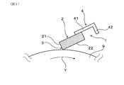
- FIG. 3 is an explanatory diagram schematically illustrating an example of a usage state of the cleaning blade of Example 1.
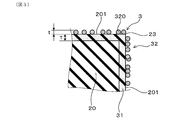
- FIG. 3 is a diagram schematically showing a cross section of the cleaning blade of Example 1.
- FIG. 3 is an explanatory diagram schematically showing an enlarged cross section of an edge portion in the cleaning blade of Example 1 shown in FIG. 2. It is a scanning transmission electron microscope (STEM) image of a cross section perpendicular
- STEM scanning transmission electron microscope
- the cleaning blade will be described.
- the cleaning blade is used to remove residual toner remaining on the surface of the mating member in the electrophotographic apparatus.
- the electrophotographic apparatus include an electrophotographic copying machine using a charged image, an image forming apparatus such as a printer, a facsimile machine, a multifunction machine, and an on-demand printing machine.
- the counterpart member include an image carrier such as a photosensitive drum, an intermediate transfer belt, and a charging roll.
- the intermediate transfer belt is used to primarily transfer the toner image carried on the image carrier to the belt, and then secondarily transfer the toner image from the belt to a transfer material such as paper.
- the cleaning blade includes a polyurethane blade portion having an edge portion for sliding contact with a mating member.
- the blade portion can have a plate-like shape, for example.
- the edge portion can include a ridge line formed by the intersection of the first blade surface and the second blade surface adjacent to the first blade surface. More specifically, the cleaning blade can be used with the ridgeline of the edge portion in contact with the mating member. In this case, both the first blade surface and the second blade surface are arranged so as to face the mating member side during use.
- the first blade surface can be the tip surface of the blade portion
- the second blade portion can be one plate surface of the blade portion.
- the edge portion has a base material containing polyurethane, an impregnation treatment layer, and a particle layer.
- the substrate can contain various known additives used in the field of cleaning blades.
- the impregnation treatment layer exists from the substrate surface to the inside of the substrate.
- the impregnation treatment layer includes a base polyurethane and an acrylic cured body.
- Such an impregnation treatment layer can be formed by impregnating an acrylic curable substance into the substrate from the surface of the substrate containing polyurethane and then curing the substrate.
- the acrylic cured body in the impregnation treatment layer may be mixed with the polyurethane of the blade part, or may be crosslinked with the polyurethane of the blade part.
- the acrylic cured body examples include acrylic resin and methacrylic resin. These can be used alone or in combination of two or more.
- the acrylic cured body is an acrylic resin or a methacrylic resin
- the acrylic cured body can be formed by impregnating the inside of the substrate with an acrylic monomer or a methacrylic monomer and then irradiating with ultraviolet rays. Therefore, according to this configuration, a cleaning blade excellent in manufacturability can be obtained.
- the thickness of the impregnated layer is preferably 50 nm or more, more preferably 75 nm or more, and still more preferably, from the viewpoint of ensuring retention of particles and suppressing drop-off of particles and improving chip durability. Can be greater than or equal to 100 nm, and even more preferably greater than or equal to 150 nm. In addition, the thickness of the impregnated layer ensures the flexibility of the edge part, makes it easy to release the stress applied to the particles by sliding contact with the mating member, suppresses the dropout of the particles, and improves the chip durability.
- it is preferably 800 nm or less, more preferably 700 nm or less, still more preferably 600 nm or less, still more preferably 500 nm or less, still more preferably 450 nm or less, and still more preferably 400 nm or less. be able to.
- the thickness of the impregnated layer is determined by measuring the cross-sectional thickness of the three impregnated layers arbitrarily from the cross-sectional image of the edge observed using a scanning transmission electron microscope (STEM). Average value.
- the base material of the blade part is polyurethane
- the cross section of the blade part including the edge part is dyed for 10 minutes with a 10% phosphotungstic acid aqueous solution, and the almost unstained part inside the base material surface is impregnated. It can be a layer.
- the impregnation treatment layer also includes polyurethane as a base material, but the impregnation treatment layer contains an acrylic cured product. For this reason, there is a difference in dyeing between the inner portion and the impregnation treatment layer than the impregnation treatment layer.
- the particle layer includes a plurality of particles held on the substrate surface.
- a particle layer does not need to be piled up in the layer thickness direction, may be piled up, and can also include both the states.
- the average particle diameter of the particles is preferably 5 nm or more, more preferably 10 nm or more, and still more preferably 15 nm or more, from the viewpoint of making it easier to improve chip durability.
- the average particle diameter of the particles is preferably 90 nm or less, more preferably 80 nm or less, still more preferably 70 nm or less, and even more preferably 60 nm or less, from the viewpoint of making it easier to improve chipping durability. Still more preferably, it can be 50 nm or less, and still more preferably 40 nm or less.
- the average particle diameter of the particles is the particle diameter measured for each selected particle by arbitrarily selecting 10 particles from the cross-sectional image of the edge observed using a scanning transmission electron microscope (STEM). Is the average value.
- the particle layer can also contain a particle aggregate in which particles are aggregated. That is, the particle layer may include a single particle, a particle aggregate, or both.
- the particle aggregate can be formed, for example, by abutting particles adjacent in the layer surface direction. According to the configuration in which the particle layer includes particle aggregates, chipping durability can be further improved.
- the number of aggregates contained in the particle layer is preferably 10 or less, more preferably 7 or less, and even more preferably 5 or less, from the viewpoint of easily improving chipping durability. can do.
- the number of particle aggregates is preferably 2 or more, more preferably 3 or more, from the viewpoint of toner scraping property and the like.
- a particle layer can contain the particle
- the thickness of the particle layer can be, for example, 3 nm or more and 200 nm or less.
- the thickness of the particle layer is preferably 5 nm or more, more preferably 10 nm or more, and further preferably 15 nm or more, from the viewpoint of ensuring the contact suppression of the counterpart member to the substrate surface. can do.
- the thickness of the particle layer is preferably 180 nm or less, more preferably 150 nm or less, still more preferably 130 nm or less, even more preferably 100 nm or less, and still more preferably, from the viewpoint of making it difficult to drop off the particles.
- the thickness of the particle layer is determined by measuring the cross-sectional thickness of the 10 particle layers arbitrarily from the cross-section (cross-section perpendicular to the substrate surface) image of the edge portion observed using a scanning transmission electron microscope (STEM), It is the average value of each measured value obtained.
- STEM scanning transmission electron microscope
- the particles include carbon particles (carbon black, etc.), metal particles (gold particles, platinum particles, silver particles, copper particles, etc.), oxide particles (iron oxide particles, zinc oxide particles, silica particles). Etc.), nitride particles (silicon nitride particles, aluminum nitride particles, etc.), polymer particles (polystyrene particles, acrylic resin particles, etc.) and the like. These can be used alone or in combination of two or more.
- the silica particles the silica particles (In Situ particles) generated in-situ in a solvent are used for the preparation of the impregnation treatment liquid used to form the impregnation treatment layer. Even when the particles are sized, it is easy to form a uniform particle layer on the surface of the substrate while avoiding poor dispersion that tends to occur with dry particles. Therefore, it is possible to obtain a cleaning blade that can easily improve the chip durability.
- any of the above-described particles may be subjected to a surface treatment.
- Specific examples of the surface treatment include coating treatment with a resin, plasma treatment, coupling treatment, and UV treatment. These can be used alone or in combination of two or more.
- the surface of the particle is coated with acrylic resin or methacrylic resin, the adhesion with the impregnated layer is improved and particle dropout due to stress applied to the particle due to sliding contact with the mating member is suppressed. It becomes easy to do. Therefore, according to this structure, it becomes easy to improve chip durability.
- the entire surface of the particle may be covered with the acrylic resin or the like, or a part of the particle surface may not be covered with the acrylic resin or the like, and the particle surface may be partially exposed. Good.
- the particles can be selected from silica particles, silica particles whose surfaces are coated with the above acrylic resin, and the like. These can be used alone or in combination of two or more.
- the area ratio of the particle layer to the impregnated layer is 5% or more and 30% or less in a cross-sectional view perpendicular to the substrate surface.
- the area ratio of the particle layer to the impregnated layer is 6% or more, preferably 7.5% or more, more preferably 10%, from the viewpoint of suppressing the drop-off of particles and improving the chip durability. As mentioned above, More preferably, it can be 15% or more.
- the area ratio of the particle layer to the impregnated layer ensures the flexibility of the edge, makes it easy to release the stress applied to the particle by sliding contact with the mating member, suppresses the dropout of the particle, and improves the chip durability. From the viewpoint of facilitating the reduction, it may be 29% or less, preferably 27.5% or less, and more preferably 25% or less.
- the area ratio of the particle layer to the impregnated layer is obtained by obtaining a cross-sectional image of the edge portion (a cross-section perpendicular to the substrate surface) using a scanning transmission electron microscope (STEM).
- STEM scanning transmission electron microscope
- the area of the particle layer can be obtained and calculated from the equation 100 ⁇ area of particle layer / area of impregnation layer.
- the present manufacturing method A method for manufacturing the cleaning blade (hereinafter sometimes referred to as “the present manufacturing method”) will be described.
- the impregnation treatment liquid is applied to the surface of the base material containing polyurethane.
- the base material is the same as that described for the cleaning blade, and a description thereof will be omitted.
- the impregnation treatment liquid contains an acrylic curable substance and particles.
- an acrylic curable substance photocurable monomers, such as an ultraviolet curable monomer, etc. can be illustrated, for example.
- Specific examples of the photocurable monomer include acrylic monomers and methacrylic monomers that are ultraviolet curable monomers. These can be used alone or in combination of two or more.
- the particles specifically, for example, the above-described particles can be exemplified. These can be used alone or in combination of two or more.
- the particles contained in the impregnation treatment liquid can be In Situ particles.
- the impregnation treatment liquid containing In Situ particles can be prepared, for example, by mixing an acrylic curable substance and a particle-containing liquid containing particles generated in-situ in a solvent in a solvent.
- the impregnation treatment liquid can further contain a photoinitiator or the like.
- the In Situ particles can be preferably In Situ silica particles.
- the impregnation treatment liquid is applied so as to include the edge portion surface of the blade portion.
- the coating method for example, various coating methods such as a dipping method, a brush coating method, and a spray method can be applied.
- the coating conditions such as the solid content, the coating amount, and the coating time of the above-described impregnation treatment liquid can be adjusted so that the thickness of the impregnation treatment layer is 30 nm or more and less than 1000 nm.
- the acrylic curable material impregnated from the substrate surface to the inside of the substrate by the above application is cured.
- the impregnation process layer containing the polyurethane of a base material and an acrylic hardening body is formed from the base material surface to the inside of a base material.
- Example 1 The cleaning blade of Example 1 will be described with reference to FIGS. As shown in FIGS. 1 to 3, the cleaning blade 1 of this example is a residual toner remaining on the surface of the mating member 9 in the electrophotographic apparatus (not shown, including not only toner but also a toner external additive). It is used for removing.
- the counterpart member 9 is specifically a photosensitive drum. The photosensitive drum rotates in the direction of arrow Y shown in FIG.
- the cleaning blade 1 includes a polyurethane blade portion 2 having an edge portion 3 for sliding contact with a mating member 9.
- the polyurethane is a non-foamed polyurethane rubber.
- the blade part 2 has shown the example which exhibits a long plate-shaped shape.
- the cleaning blade 1 further includes a support body 4 having a plate-like portion 41 and an attachment portion 42 that is integrally connected to the plate-like portion 41.
- the blade portion 2 is joined to one plate surface of the plate-like portion 41 in the support 4.
- the cleaning blade 1 may have the front end portion of the plate-like portion 41 of the support 4 embedded in the rear end portion of the blade portion 2.
- the edge portion 3 includes a base material 20 including polyurethane, an impregnation treatment layer 31 existing in a certain region from the surface 201 of the base material 20 to the inside of the base material 20, and the base material 20. And a particle layer 32 including particles 320 held on the surface 201.
- the impregnation treatment layer 31 includes polyurethane that forms the base material 20 and an acrylic cured body.
- the acrylic cured body is at least one selected from the group consisting of an acrylic resin and a methacrylic resin.
- the particles are silica particles.
- the average particle diameter of the particles is in the range of 3 nm to 100 nm.
- the thickness T of the impregnated layer 31 is in the range of 30 nm or more and less than 1000 nm.
- the thickness t of the particle layer 32 is in the range of 3 nm to 200 nm.
- the area ratio of the particle layer 32 to the impregnation treatment layer 31 is 5% or more and 30% or less in a cross-sectional view perpendicular to the surface of the substrate 20.
- the edge portion 3 includes a ridge line 23 formed by the intersection of the first blade surface 21 and the second blade surface 22.
- the first blade surface 21 is the tip surface of the blade portion 2
- the second blade surface 22 is one plate surface of the blade portion 2. Both the first blade surface 21 and the second blade surface 22 are arranged so as to face the mating member 9 side during use.
- the impregnation treatment layer 31 exists over the entire surface direction of the first blade surface 21 starting from the ridge line 23.
- the impregnation treatment layer 31 exists up to any one of the range of the second blade surface 22 that is 1/2 or less of the surface direction of the second blade surface 22 starting from the ridge line 23.
- the particle layer 32 also exists in the same range as the impregnation treatment layer 31. That is, in this example, the impregnation treatment layer 31 extends also to the inside of the base material 20 outside the edge portion 3 in order to improve the coatability of the impregnation treatment liquid during production. Further, the particle layer 32 extends also on the surface of the base material 20 outside the edge portion 3.
- the manufacturing method of this example is a method by which the cleaning blade 1 of this example can be manufactured.
- an impregnation treatment liquid containing an acrylic curable substance and particles is applied to the surface of a base material containing polyurethane.
- an impregnation treatment layer including an acrylic cured body obtained by curing the acrylic curable substance by impregnating the acrylic curable substance from the substrate surface to the inner side of the substrate and then curing the acrylic curable substance, and the base polyurethane. Is formed.
- grain is formed with the particle
- the acrylic curable substance is at least one of an acrylic monomer and a methacrylic monomer.
- the particles contained in the impregnation treatment liquid are In Situ silica particles.
- polybutylene adipate (Tosoh Corp., “Nipporan 4010”): 87 parts by mass, 1,4-butanediol (Mitsubishi Chemical Corp.) and trimethylolpropane (Guangei Perstorp)
- Low molecular weight polyol mixed at 6 4: 13 parts by mass and triethylenediamine as a catalyst (manufactured by Tosoh Corporation): 0.01 part by mass in a nitrogen atmosphere at 80 ° C. for 1 hour.
- a curing agent solution having a hydroxyl value (OHV) of 210 KOHmg / g
- the prepared main agent solution and curing agent solution are mixed at a blending ratio of 94 parts by mass of the curing agent solution with respect to 100 parts by mass of the main agent solution in a vacuum atmosphere at 60 ° C. for 3 minutes, and sufficiently defoamed. did. Thereby, a urethane rubber composition was prepared.
- impregnation treatment liquid (1-2) solid content 1%) having different solid contents
- the impregnation treatment liquid (1-3) Solid content 3%
- impregnation liquid (1-4) solid content 5%
- impregnation liquid (1-5) solid content 15%
- impregnation liquid (1-6) solid content 50%
- impregnation solution (1-7) solid content: 70%
- -Impregnation solution (2)- In the preparation of the impregnation treatment liquid (1), 5 parts by mass (conversion of particle mass) of a particle-containing liquid (manufactured by C-I Kasei Co., Ltd., “Nano Tek SiO-10”, containing silica particles by In Situ, average particle size: 10 nm), methyl ethyl ketone An impregnation solution (2) was prepared in the same manner except that the amount was 990 parts by mass.
- -Impregnation solution (4) 100 parts by mass of pentaerythritol triacrylate (“Aronix M305” manufactured by Toagosei Co., Ltd.) as an acrylic monomer, and 2-hydroxy-2-methyl-1-phenyl-propan-1-one as a radical photopolymerization initiator ( 5 parts by mass of BASF, “Irgacure 1173” and 5 parts by mass of a particle-containing liquid (BYK, “Nano BYK3605”, silica particles containing In Situ coated with acrylic resin on the surface, average particle diameter: 20 nm)
- An impregnation solution (4) was prepared by mixing (particle mass conversion) and 990 parts by mass of methyl ethyl ketone.
- -Impregnation solution (5) 100 parts by mass of pentaerythritol triacrylate (“Aronix M305” manufactured by Toagosei Co., Ltd.) as an acrylic monomer, and 2-hydroxy-2-methyl-1-phenyl-propan-1-one as a radical photopolymerization initiator ( By mixing 5 parts by mass of “Irgacure 1173” manufactured by BASF, 5 parts by mass of carbon black (“Seast 3” manufactured by Tokai Carbon Co., Ltd., average particle diameter: 28 nm) as particles, and 990 parts by mass of methyl ethyl ketone An impregnation solution (5) was prepared.
- an impregnation treatment liquid (7) was prepared in the same manner except that no particle-containing liquid was blended.
- a mold composed of an upper mold and a lower mold was prepared.
- the upper mold and the lower mold are brought close to each other and clamped to form a cavity having a size corresponding to two substantially long plate-like blade portions.
- the cavity is provided with two opposing storage portions.
- Each of these accommodating portions is configured such that a plate-like portion of a metal support made of a long metal plate (plate thickness 2 mm) bent in an L-shaped cross section can be disposed.
- an epoxy adhesive (“Aronmighty AS-60” manufactured by Toagosei Co., Ltd.) was applied to one plate surface of the plate-like portion of the support.
- a support coated with an adhesive is set in each housing part of the mold and the mold is clamped.
- the prepared urethane rubber composition is injected into the cavity and heated at 130 ° C. for 10 minutes.
- the urethane rubber composition was cured by Thereafter, the molded body was taken out from the mold and cut into two pieces to have a predetermined size.
- a plate-like blade portion made of polyurethane rubber as a base material blade thickness: 2 mm, blade width: 10 mm
- the bonding width between the blade part and the support was 2 mm.
- each impregnation treatment liquid is adjusted so that the thickness of the impregnation treatment layer becomes a value shown in Table 1. Thereafter, the blade portion was separated from the impregnation solution.
- an ultraviolet lamp (mercury lamp type) of the ultraviolet irradiation device is applied to the portion subjected to the impregnation treatment on the surface of the blade portion.
- the impregnation liquid was cured by irradiating with ultraviolet rays under irradiation conditions of a distance of 200 mm from the ridge line of the blade part, an ultraviolet intensity of 100 mW / cm 2 , and an irradiation time of 30 seconds.
- the acrylic monomer as the acrylic curable substance almost impregnated from the substrate surface to the inside of the substrate was cured, and an impregnation treatment layer containing an acrylic resin and polyurethane was formed.
- an impregnation treatment layer containing an acrylic resin and polyurethane was formed.
- a particle layer was formed by the particles in the impregnation treatment liquid remaining on the surface of the base material without impregnating the inside of the base material.
- a cleaning blade for each sample having an edge portion having the configuration shown in Table 1 was obtained.
- the thickness of the impregnation treatment layer and the particle layer and the average particle diameter of the particles in Table 1 were measured by the measurement method described above. In the measurement, the blade section was stained with the 10% phosphotungstic acid aqueous solution described above.
- the area ratio of the particle layer with respect to the impregnation process layer in Table 1 was computed by the method mentioned above.
- ⁇ Chip durability> The blade portion of the cleaning blade of each sample was assembled so that the edge line of the edge portion was in sliding contact with the photosensitive drum of a commercially available laser beam printer. Then, 100,000 sheets were printed using A4 size paper in an environment of 10% ⁇ 10% RH. After the endurance, the case where no chipping occurred in the edge part of the blade part was designated as “A +” as excellent chipping durability. In addition, when the edge portion of the blade portion was chipped within the range of 1 to 9, “A” was given as the chip durability was good. The case where chipping occurred in the edge portion of the blade portion with 10 or more and less than 20 was designated as “C” because improvement in chipping durability was not observed. A case where 20 or more chips occurred in the edge portion of the blade portion was designated as “D” because no improvement in chip durability was observed.
- FIG. 4 is a scanning transmission electron microscope (STEM) image (200,000 times) of a cross section perpendicular to the substrate surface of the edge portion of Sample 6 as a representative diagram of Sample 1 to Sample 9.
- STEM scanning transmission electron microscope
- the cleaning blade of the sample 6C does not have a particle layer on the surface of the impregnation treatment layer. Therefore, in the cleaning blade of the sample 6C, the substrate surface at the edge portion is in contact with the surface of the photosensitive drum from the beginning. Therefore, the surface of the impregnated layer is scraped from the initial stage by the friction caused by sliding contact with the photosensitive drum, and the low friction effect of the impregnated layer is eliminated early during the above-described durability, and the chip 6C cleaning blade has improved durability.
- the chip 6C cleaning blade has improved durability.
- the cleaning blade of Sample 1C has a particle layer, but the average particle diameter of the particles exceeds the upper limit. Therefore, the chip 1C cleaning blade could not improve chipping durability even when the thickness of the impregnation layer was within the specified range.
- the average particle diameter of the particles in the particle layer is within the specific range.
- the thickness of the impregnated layer exceeds the upper limit. Therefore, the cleaning blade of sample 2C could not improve the chip durability. This is because the surface hardness of the edge portion becomes excessive due to the use of the impregnated layer whose thickness exceeds the upper limit, and the flexibility of the edge portion is reduced, and the stress applied to the particles by the sliding contact with the photosensitive drum is released. This is because the particles could not be removed and the dropout of the particles was accelerated.
- the average particle diameter of the particles in the particle layer is within the specific range.
- the thickness of the impregnation layer is below the lower limit. Therefore, the cleaning blade of Sample 3C could not improve the chip durability. This is because the use of the impregnation treatment layer having a thickness lower than the lower limit weakens the retention force of the particles and accelerates the dropout of the particles.
- the area ratio of the particle layer to the impregnated layer is below the lower limit. Therefore, the chip 4C cleaning blade could not improve chip durability. This is because it is difficult to suppress the drop-off of particles when the area ratio of the particle layer to the impregnation treatment layer is below the lower limit.
- the area ratio of the particle layer to the impregnation treatment layer is below the upper limit. Therefore, the cleaning blade of sample 5C could not improve the chip durability. This is because when the area ratio of the particle layer to the impregnated layer exceeds the upper limit, the flexibility of the edge portion is reduced, and it is difficult to release the stress applied to the particle by sliding contact with the mating member, and the drop of the particle is suppressed. This is because it became difficult.
- the cleaning blades of Sample 1 to Sample 9 have the above-described configuration.
- the average particle diameter of the particles in the particle layer, the thickness of the impregnation treatment layer, and the area ratio of the particle layer to the impregnation treatment layer are in the specific range. Therefore, according to the cleaning blades of Sample 1 to Sample 9, the chip durability could be improved as compared with the cleaning blade of Sample 4C having the edge portion provided with only the impregnated layer. This is due to the following reason.
- the surface of the base material is reduced in friction by the impregnation treatment layer including the base material polyurethane rubber and the acrylic cured body. Further, when the surface of the edge portion is in sliding contact with the photosensitive drum, the particles of the particle layer disposed on the surface of the base material reduced in friction come into contact with the photosensitive drum before the surface of the base material. Therefore, the contact area with the photosensitive drum is reduced. As a result, the surface of the impregnated layer is slowly scraped by friction due to the sliding contact with the photosensitive drum, and the low friction effect of the impregnated layer is easily exhibited over a long period of time. As a result, the cleaning blades of Sample 1 to Sample 9 were able to improve chipping durability.
Landscapes
- Physics & Mathematics (AREA)
- General Physics & Mathematics (AREA)
- Cleaning In Electrography (AREA)
- Electrophotography Configuration And Component (AREA)
- Electrostatic Charge, Transfer And Separation In Electrography (AREA)
Abstract
欠け耐久性を向上させることが可能なクリーニングブレード(1)を提供する。クリーニングブレード(1)は、相手部材(9)と摺接させるためのエッジ部(3)を有するポリウレタン製のブレード部(2)を備えている。エッジ部(3)は、ポリウレタンを含む基材(20)と、基材(20)の表面(201)から基材(20)の内側にわたって存在しており、基材(20)のポリウレタンとアクリル系硬化体とを含む含浸処理層(31)と、基材(20)の表面(201)に保持された粒子(320)を含む粒子層(32)とを有している。粒子(320)の平均粒子径は、3nm以上100nm以下である。含浸処理層(31)の厚みは、30nm以上1000nm未満である。エッジ部(3)は、基材(20)表面に垂直な断面視で、含浸処理層(31)に対する粒子層(32)の面積比率が5%以上30%以下である。
Description
本発明は、クリーニングブレードおよびその製造方法に関する。
従来、電子写真機器では、感光体等の像担持体や中間転写ベルトなどの相手部材の表面をクリーニングするため、クリーニングブレードが用いられている。クリーニングブレードは、相手部材と摺接させるためのエッジ部を有するブレード部を備えている。ブレード部のエッジ部が相手部材の表面に押し付けられることにより、表面移動する相手部材表面の残留トナーが掻き取られる。
この種のクリーニングブレードとしては、例えば、ブレード部にアクリレートを数十μm~数百μm程度含浸させた後、硬化させることにより、エッジ部に含浸処理層を形成したクリーニングブレードが知られている。
なお、先行する特許文献1には、感光体表面に当接するブレードエッジを含む端部に微粒子を付着させた後、付着した微粒子に液状接着剤を含浸させることによって粒子層を形成してなるクリーニングブレードが開示されている。
しかしながら、従来技術は、以下の点で課題がある。クリーニングブレードのエッジ部は、相手部材との摺接による摩擦によって欠けやすい。従来知られるクリーニングブレードは、エッジ部に含浸処理層を形成することによって表面を低摩擦化し、摺接による欠けを抑制しようとするものである。
ところが、近年、画像形成装置の耐久性向上が求められており、これに伴い、クリーニングブレードも、これまで以上に欠けに対する耐久性が求められるようになってきている。つまり、エッジ部に含浸処理層を形成するだけでは、近年求められる欠け耐久性が十分ではなく、さらなる欠け耐久性の向上が望まれている。
本発明は、上記背景に鑑みてなされたものであり、欠け耐久性を向上させることが可能なクリーニングブレードを提供しようとするものである。
本発明の一態様は、電子写真機器内において相手部材の表面に残留する残留トナーを除去するために用いられるクリーニングブレードであって、
上記相手部材と摺接させるためのエッジ部を有するポリウレタン製のブレード部を備え、
上記エッジ部は、ポリウレタンを含む基材と、上記基材表面から上記基材内側にわたって存在しており、上記基材のポリウレタンとアクリル系硬化体とを含む含浸処理層と、上記基材表面に保持された粒子を含む粒子層とを有しており、
上記粒子の平均粒子径は、3nm以上100nm以下であり、
上記含浸処理層の厚みは、30nm以上1000nm未満であり、
上記基材表面に垂直な断面視で、上記含浸処理層に対する上記粒子層の面積比率が5%以上30%以下である、クリーニングブレードにある。
上記相手部材と摺接させるためのエッジ部を有するポリウレタン製のブレード部を備え、
上記エッジ部は、ポリウレタンを含む基材と、上記基材表面から上記基材内側にわたって存在しており、上記基材のポリウレタンとアクリル系硬化体とを含む含浸処理層と、上記基材表面に保持された粒子を含む粒子層とを有しており、
上記粒子の平均粒子径は、3nm以上100nm以下であり、
上記含浸処理層の厚みは、30nm以上1000nm未満であり、
上記基材表面に垂直な断面視で、上記含浸処理層に対する上記粒子層の面積比率が5%以上30%以下である、クリーニングブレードにある。
本発明の他の態様は、上記クリーニングブレードの製造方法であって、
ポリウレタンを含む基材の表面に、アクリル系硬化性物質と粒子とを含む含浸処理液を塗工し、
上記基材表面から上記基材内側に上記アクリル系硬化性物質を含浸させた後に硬化させることによって、上記アクリル系硬化性物質が硬化してなるアクリル系硬化体と上記基材のポリウレタンとを含む含浸処理層を形成するとともに、
上記基材内側に含浸することなく上記基材表面に残った上記粒子によって、上記粒子を含む粒子層を形成する、クリーニングブレードの製造方法にある。
ポリウレタンを含む基材の表面に、アクリル系硬化性物質と粒子とを含む含浸処理液を塗工し、
上記基材表面から上記基材内側に上記アクリル系硬化性物質を含浸させた後に硬化させることによって、上記アクリル系硬化性物質が硬化してなるアクリル系硬化体と上記基材のポリウレタンとを含む含浸処理層を形成するとともに、
上記基材内側に含浸することなく上記基材表面に残った上記粒子によって、上記粒子を含む粒子層を形成する、クリーニングブレードの製造方法にある。
上記クリーニングブレードは、上記構成を有している。上記クリーニングブレードでは、基材のポリウレタンとアクリル系硬化体とを含む含浸処理層により、基材表面が低摩擦化される。また、エッジ部の表面が相手部材と摺接する際には、低摩擦化された基材表面に配置された粒子層の粒子が、基材表面よりも先に相手部材に接触する。そのため、相手部材との接触面積が減少する。その結果、相手部材との摺接による摩擦によって、含浸処理層の表面が削られるのが遅くなり、含浸処理層の低摩擦効果が長期にわたって発揮されやすくなる。
但し、上記作用効果は、粒子層の粒子の平均粒子径、含浸処理層の厚み、含浸処理層に対する粒子層の面積比率が上記特定の範囲にあるときに発揮される。粒子層の粒子の平均粒子径が上記特定の範囲にある場合において、含浸処理層の厚みが、上述した下限値を下回ると、粒子の保持力が弱くなり、粒子の脱落が早くなって欠け耐久性を向上させることができなくなる。一方、含浸処理層の厚みが、上述した上限値を上回ると、エッジ部の表面硬度が過度になってエッジ部の柔軟性が低下し、相手部材との摺接によって粒子にかかる応力を逃がすことができなくなり、粒子の脱落が早くなって欠け耐久性を向上させることができなくなる。また、含浸処理層に対する粒子層の面積比率が上記範囲外になると、欠け耐久性を向上させることができなくなる。
よって、上記クリーニングブレードによれば、含浸処理層だけを備えるエッジ部を有するクリーニングブレードに比べ、欠け耐久性を向上させることが可能となる。
また、上記クリーニングブレードの製造方法によれば、欠け耐久性を向上させることが可能な上記クリーニングブレードを製造することができる。
上記クリーニングブレードについて説明する。
上記クリーニングブレードは、電子写真機器内において相手部材の表面に残留する残留トナーを除去するために用いられるものである。電子写真機器としては、具体的には、帯電像を用いる電子写真方式の複写機、プリンター、ファクシミリ、複合機、オンデマンド印刷機等の画像形成装置などを例示することができる。また、相手部材としては、感光ドラム等の像担持体や中間転写ベルト、帯電ロールなどを例示することができる。なお、中間転写ベルトは、像担持体に担持されたトナー像を当該ベルトに一次転写した後、このトナー像を当該ベルトから用紙等の転写材へ二次転写するためのものである。
上記クリーニングブレードは、相手部材と摺接させるためのエッジ部を有するポリウレタン製のブレード部を備えている。ブレード部は、例えば、板状の形状を呈することができる。エッジ部は、具体的には、第1ブレード面と第1ブレード面に隣接する第2ブレード面との交わりより構成される稜線を含むことができる。上記クリーニングブレードは、より具体的には、エッジ部の稜線を相手部材と当接させて使用することができる。この場合、第1ブレード面および第2ブレード面は、いずれも、使用時に相手部材側に向くように配置される。ブレード部が板状の形状を呈する場合、第1ブレード面はブレード部の先端面、第2ブレード部はブレード部の一方の板面とすることができる。
エッジ部は、ポリウレタンを含む基材と、含浸処理層と、粒子層とを有している。基材は、ポリウレタン以外にも、クリーニングブレードの分野で用いられている公知の各種添加剤などを含むことができる。
含浸処理層は、基材表面から基材内側にわたって存在している。含浸処理層は、基材のポリウレタンとアクリル系硬化体とを含んでいる。このような含浸処理層は、ポリウレタンを含む基材表面から基材内部にアクリル系硬化性物質を含浸させた後に硬化させることによって形成することができる。含浸処理層におけるアクリル系硬化体は、ブレード部のポリウレタンと混合されていてもよいし、ブレード部のポリウレタンと架橋等していてもよい。
アクリル系硬化体としては、例えば、アクリル樹脂、メタクリル樹脂などを例示することができる。これらは1種または2種以上併用することができる。アクリル系硬化体がアクリル樹脂、メタクリル樹脂である場合には、アクリルモノマー、メタクリルモノマーを基材内部に含浸させた後、紫外線を照射することにより、アクリル系硬化体を形成することができる。そのため、この構成によれば、製造性に優れたクリーニングブレードが得られる。
含浸処理層の厚みは、粒子の保持力を確保して粒子の脱落を抑制し、欠け耐久性を向上させやすくするなどの観点から、好ましくは、50nm以上、より好ましくは、75nm以上、さらに好ましくは、100nm以上、さらにより好ましくは、150nm以上とすることができる。また、含浸処理層の厚みは、エッジ部の柔軟性を確保し、相手部材との摺接によって粒子にかかる応力を逃がしやすくして粒子の脱落を抑制し、欠け耐久性を向上させやすくするなどの観点から、好ましくは、800nm以下、より好ましくは、700nm以下、さらに好ましくは、600nm以下、さらにより好ましくは、500nm以下、さらに一層好ましくは、450nm以下、さらにより一層好ましくは、400nm以下とすることができる。
含浸処理層の厚みは、走査透過型電子顕微鏡(STEM)を用いて観察されるエッジ部の断面像から、任意に3箇所の含浸処理層の断面厚みを測定し、得られた各測定値の平均値である。なお、ブレード部の基材がポリウレタンであるため、10%リンタングステン酸水溶液にてエッジ部を含むブレード部の断面を10分間染色し、基材表面より内側のほとんど染色されていない部分を含浸処理層とすることができる。なぜなら、含浸処理層にも基材のポリウレタンが含まれるが、含浸処理層にはアクリル系硬化体が含まれている。そのため、含浸処理層よりもさらに内側の部分と含浸処理層との染色に差が生じるためである。
粒子層は、基材表面に保持された複数の粒子を含んでいる。なお、粒子層は、層厚み方向で、粒子が積み重なっていなくてもよいし、積み重なっていてもよいし、その両方の状態を含むこともできる。粒子の平均粒子径は、欠け耐久性をより向上させやすくするなどの観点から、好ましくは、5nm以上、より好ましくは、10nm以上、さらに好ましくは、15nm以上とすることができる。また、粒子の平均粒子径は、欠け耐久性をより向上させやすくするなどの観点から、好ましくは、90nm以下、より好ましくは、80nm以下、さらに好ましくは、70nm以下、さらにより好ましくは、60nm以下、さらに一層好ましくは、50nm以下、さらにより一層好ましくは、40nm以下とすることができる。
粒子の平均粒子径は、走査透過型電子顕微鏡(STEM)を用いて観察されるエッジ部の断面像から、任意に粒子を10個を選択し、選択された各粒子について測定される粒子の直径の平均値である。
また、粒子層は、粒子が凝集した粒子凝集体を含むこともできる。つまり、粒子層は、単独の粒子を含んでいてもよいし、粒子凝集体を含んでいてもよいし、その両方を含んでいてもよい。粒子凝集体は、例えば、層面方向で隣り合う粒子同士が当接して形成されることができる。粒子層が粒子凝集体を含む構成によれば、欠け耐久性をより向上させやすくなる。粒子層に含まれる凝集体の個数は、具体的には、欠け耐久性をより向上させやすくするなどの観点から、好ましくは10個以下、より好ましくは7個以下、さらに好ましくは5個以下とすることができる。また、粒子凝集体の個数は、トナー掻き取り性などの観点から、好ましくは2個以上、より好ましくは3個以上とすることができる。なお、粒子凝集体は、欠け耐久性をより向上させやすくするなどの観点から、粒子層の厚み方向に積み重なっていないことが好ましい。また、粒子層は、粒子外周面のうち、基材表面側の端面にてアクリル系硬化体の一部によって基材表面に保持された粒子を含むことができる。
粒子層の厚みは、例えば、3nm以上200nm以下とすることができる。粒子層の厚みは、基材表面への相手部材の接触抑制を確実なものにするなどの観点から、好ましくは、好ましくは、5nm以上、より好ましくは、10nm以上、さらに好ましくは、15nm以上とすることができる。また、粒子層の厚みは、粒子を脱落させ難くなるなどの観点から、好ましくは、180nm以下、より好ましくは、150nm以下、さらに好ましくは、130nm以下、さらにより好ましくは、100nm以下、さらに一層好ましくは、50nm以下、さらにより一層好ましくは、50nm未満、最も好ましくは、45nm以下とすることができる。
粒子層の厚みは、走査透過型電子顕微鏡(STEM)を用いて観察されるエッジ部の断面(基材表面に垂直な断面)像から、任意に10箇所の粒子層の断面厚みを測定し、得られた各測定値の平均値である。
粒子としては、具体的には、例えば、炭素粒子(カーボンブラック等)、金属粒子(金粒子、白金粒子、銀粒子、銅粒子等)、酸化物粒子(酸化鉄粒子、酸化亜鉛粒子、シリカ粒子等)、窒化物粒子(窒化ケイ素粒子、窒化アルミニウム粒子等)、ポリマー粒子(ポリスチレン粒子、アクリル樹脂粒子等)などを例示することができる。これらは1種または2種以上併用することができる。粒子がシリカ粒子である場合には、溶媒中にてその場生成させたシリカ粒子(In Situ粒子)を、含浸処理層の形成に用いる含浸処理液の調製に用いることで、上記のようなナノサイズの粒子であっても、乾燥した粒子で生じやすい分散不良を回避しつつ、基材表面に均一に粒子層を形成しやすくなる。そのため、欠け耐久性の向上をより確実なものとしやすいクリーニングブレードが得られる。
上述した粒子は、いずれも、表面処理が施されていてもよい。表面処理としては、具体的には、樹脂による被覆処理、プラズマ処理、カップリング処理、UV処理などを例示することができる。これらは1種または2種以上併用することができる。中でも、粒子の表面がアクリル樹脂、メタクリル樹脂によって被覆されている場合には、含浸処理層との接着力が向上し、相手部材との摺接によって粒子にかかる応力に起因する粒子の脱落を抑制しやすくなる。そのため、この構成によれば、欠け耐久性をより向上させやすくなる。なお、粒子の表面全体が上記アクリル樹脂等によって被覆されていてもよいし、粒子の表面の一部が上記アクリル樹脂等によって被覆されておらず、粒子の表面が部分的に露出していてもよい。好ましくは、含浸処理層との接着性向上などの観点から、前者であるとよい。粒子は、欠け耐久性の向上をより確実なものとするなどの観点から、シリカ粒子、上記アクリル樹脂等により表面が被覆されたシリカ粒子などを好適なものとして選択することができる。これらは1種または2種以上併用することができる。
エッジ部は、基材表面に垂直な断面視で、含浸処理層に対する粒子層の面積比率が5%以上30%以下とされている。含浸処理層に対する粒子層の面積比率が上記範囲外になると、欠け耐久性を向上させることができなくなる。含浸処理層に対する粒子層の面積比率は、粒子の脱落を抑制し、欠け耐久性を向上させやすくするなどの観点から、6%以上、好ましくは、7.5%以上、より好ましくは、10%以上、さらに好ましくは、15%以上とすることができる。また、含浸処理層に対する粒子層の面積比率は、エッジ部の柔軟性を確保し、相手部材との摺接によって粒子にかかる応力を逃がしやすくして粒子の脱落を抑制し、欠け耐久性を向上させやすくするなどの観点から、29%以下、好ましくは、27.5%以下、より好ましくは、25%以下とすることができる。
含浸処理層に対する粒子層の面積比率は、走査透過型電子顕微鏡(STEM)を用いてエッジ部の断面(基材表面に垂直な断面)像を取得し、その断面像について、含浸処理層の面積、粒子層の面積を求め、100×粒子層の面積/含浸処理層の面積の式から算出することができる。
上記クリーニングブレードの製造方法(以下、「本製造方法」ということがある。)について説明する。
本製造方法では、ポリウレタンを含む基材の表面に含浸処理液が塗工される。なお、基材については、上記クリーニングブレードで説明した通りであるので、説明は省略する。
含浸処理液は、アクリル系硬化性物質と粒子とを含んでいる。アクリル系硬化性物質としては、例えば、紫外線硬化性モノマー等の光硬化性モノマーなどを例示することができる。光硬化性モノマーとしては、具体的には、紫外線硬化性モノマーであるアクリルモノマー、メタクリルモノマー等を例示することができる。これらは1種または2種以上併用することができる。
一方、粒子としては、具体的には、例えば、上述した粒子を例示することができる。これらは1種または2種以上併用することができる。
含浸処理液に含まれる粒子は、In Situ粒子とすることができる。In Situ粒子を含む含浸処理液は、例えば、溶剤に、アクリル系硬化性物質と、溶媒中にてその場生成させた粒子を含む粒子含有液とを混合することなどによって調製することができる。硬化性物質が光硬化性モノマーである場合、含浸処理液は、光開始剤などをさらに含有することができる。In Situ粒子は、好ましくは、In Situシリカ粒子とすることができる。
含浸処理液の塗布は、ブレード部のエッジ部表面を含むように塗布することができればよい。塗布方法としは、例えば、ディッピング法、刷毛塗り法、スプレー法などの各種の塗布方法を適用することができる。なお、含浸処理層の厚みが30nm以上1000nm未満となるように、上述した含浸処理液の固形分量、塗工量、塗工時間等の塗工条件を調節することができる。
本製造方法では、上記塗布によって基材表面から基材内側に含浸させたアクリル系硬化性物質を硬化させる。これにより、基材表面から基材内側にわたって、基材のポリウレタンとアクリル系硬化体とを含む含浸処理層が形成される。
本製造方法では、含浸処理液中に粒子が含まれている。そのため、本製造方法では、含浸処理液中のアクリル系硬化性物質は選択的に基材内側に含浸していくが、粒子は基材内側に含浸することなく基材表面に残る。本製造方法では、この基材表面に残った粒子によって粒子層が形成される。本製造方法では、具体的には、含浸処理液のモノマー成分が基材内部へ含浸した後、粒子外周面を濡らしていた一部のモノマー成分を硬化させることなどによって、基材表面に粒子を保持させることができる。この場合には、極めて少量のモノマー成分の使用で粒子を基材表面に保持させることができる。
なお、上述した各構成は、上述した各作用効果等を得るなどのために必要に応じて任意に組み合わせることができる。
以下、実施例のクリーニングブレードについて、図面を用いて説明する。
(実施例1)
実施例1のクリーニングブレードについて、図1~図3を用いて説明する。図1~図3に示されるように、本例のクリーニングブレード1は、電子写真機器内において相手部材9の表面に残留する残留トナー(不図示、トナーのみならず、トナー外添剤も含む)を除去するために用いられるものである。本例では、相手部材9は、具体的には、感光ドラムである。なお、感光ドラムは、図1に示される矢印Yの方向に回転する。
実施例1のクリーニングブレードについて、図1~図3を用いて説明する。図1~図3に示されるように、本例のクリーニングブレード1は、電子写真機器内において相手部材9の表面に残留する残留トナー(不図示、トナーのみならず、トナー外添剤も含む)を除去するために用いられるものである。本例では、相手部材9は、具体的には、感光ドラムである。なお、感光ドラムは、図1に示される矢印Yの方向に回転する。
クリーニングブレード1は、相手部材9と摺接させるためのエッジ部3を有するポリウレタン製のブレード部2を備えている。本例では、ポリウレタンは、非発泡ポリウレタンゴムである。また、各図では、ブレード部2は、長尺の板状の形状を呈する例が示されている。本例では、クリーニングブレード1は、具体的には、板状部41と板状部41と一体的に繋がる取付部42とを有する支持体4をさらに備えている。ブレード部2は、支持体4における板状部41の一方の板面に接合されている。なお、図示はしないが、クリーニングブレード1は、支持体4における板状部41の先端部が、ブレード部2の後端部に埋設されていてもよい。
図3に示されるように、エッジ部3は、ポリウレタンを含む基材20と、基材20の表面201から基材20の内側にわたって一定の領域で存在する含浸処理層31と、基材20の表面201に保持された粒子320を含む粒子層32とを有している。含浸処理層31は、基材20を形成するポリウレタンとアクリル系硬化体とを含んでいる。本例では、アクリル系硬化体は、アクリル樹脂、および、メタクリル樹脂からなる群より選択される少なくとも1種である。また、粒子は、シリカ粒子である。
クリーニングブレード1において、粒子の平均粒子径は、3nm以上100nm以下の範囲とされている。また、含浸処理層31の厚みTは、30nm以上1000nm未満の範囲内とされている。なお、粒子層32の厚みtは、3nm以上200nm以下の範囲内とされている。また、エッジ部3は、基材20表面に垂直な断面視で、含浸処理層31に対する粒子層32の面積比率が5%以上30%以下とされている。
本例では、エッジ部3は、第1ブレード面21と第2ブレード面22との交わりより構成される稜線23を含んでいる。なお、第1ブレード面21は、ブレード部2の先端面であり、第2ブレード面22は、ブレード部2の一方の板面である。第1ブレード面21および第2ブレード面22は、いずれも、使用時に相手部材9側に向くように配置される。
そして、本例では、図2では省略されているが、含浸処理層31は、具体的には、稜線23を起点として第1ブレード面21の面方向全体に存在している。一方、含浸処理層31は、稜線23を起点として第2ブレード面22の面方向1/2以下の範囲のいずれかまで存在している。粒子層32も、含浸処理層31と同様の範囲で存在している。つまり、本例では、製造時における含浸処理液の塗工性向上させるため、エッジ部3の外側における基材20の内側にも含浸処理層31が延びている。また、エッジ部3の外側における基材20の表面にも粒子層32が延びている。
次に、本例のクリーニングブレードの製造方法について説明する。本例の製造方法は、本例のクリーニングブレード1を製造することができる方法である。
本例の製造方法では、ポリウレタンを含む基材の表面に、アクリル系硬化性物質と粒子とを含む含浸処理液が塗工される。次いで、基材表面から基材内側にアクリル系硬化性物質を含浸させた後に硬化させることによって、アクリル系硬化性物質が硬化してなるアクリル系硬化体と基材のポリウレタンとを含む含浸処理層が形成される。また、基材内側に含浸することなく基材表面に残った粒子によって、当該粒子を含む粒子層が形成される。
本例では、アクリル系硬化性物質は、アクリルモノマー、および、メタクリルモノマーの少なくとも1つである。また、含浸処理液に含まれる粒子は、In Situシリカ粒子である。
(実験例)
以下、上記クリーニングブレードおよびその製造方法を、実験例を用いてより具体的に説明する。
以下、上記クリーニングブレードおよびその製造方法を、実験例を用いてより具体的に説明する。
<ウレタンゴム組成物の調製>
80℃にて1時間、真空脱泡したポリブチレンアジペート(PBA)(東ソー社製、「ニッポラン4010」):44質量部と、4,4′-ジフェニルメタンジイソシアネート(MDI)(東ソー社製、「ミリオネートMT」):56質量部とを混合し、窒素雰囲気下、80℃で3時間反応させることにより、ウレタンプレポリマーを含む主剤液を調製した。なお、主剤液中のNCO%(質量%)は、17.0%である。
80℃にて1時間、真空脱泡したポリブチレンアジペート(PBA)(東ソー社製、「ニッポラン4010」):44質量部と、4,4′-ジフェニルメタンジイソシアネート(MDI)(東ソー社製、「ミリオネートMT」):56質量部とを混合し、窒素雰囲気下、80℃で3時間反応させることにより、ウレタンプレポリマーを含む主剤液を調製した。なお、主剤液中のNCO%(質量%)は、17.0%である。
また、ポリブチレンアジペート(PBA)(東ソー社製、「ニッポラン4010」):87質量部と、1,4-ブタンジオール(三菱化学社製)とトリメチロールプロパン(広栄パーストープ社製)とが重量比6:4にて混合されてなる低分子量ポリオール:13質量部と、触媒としてのトリエチレンジアミン(東ソー社製):0.01質量部とを、窒素雰囲気下、80℃にて1時間混合することにより、水酸基価(OHV)が210(KOHmg/g)の硬化剤液を調製した。
次いで、上記調製した主剤液と硬化剤液とを、主剤液100質量部に対して硬化剤液94質量部の配合割合にて、真空雰囲気下、60℃で3分間混合し、十分に脱泡した。これによりウレタンゴム組成物を調製した。
<含浸処理液の調製>
-含浸処理液(1-1)~(1-7)-
アクリルモノマーとしてのペンタエリスリトールトリアクリレート(東亞合成社製、「アロニックスM305」)100質量部と、ラジカル系光重合開始剤としての2-ヒドロキシ-2-メチル-1-フェニル-プロパン-1-オン(BASF社製、「イルガキュア1173」5質量部と、粒子含有液(シーアイ化成社製、「Nano Tek SiO-30」、In Situによるシリカ粒子含有、平均粒子径:30nm)5質量部(粒子質量換算)と、メチルエチルケトン990質量部とを混合することにより、含浸処理液(1-1)(固形分10%)を調製した。また、含浸処理液(1-1)の調製において、メチルエチルケトンの量を調節することにより、固形分量の異なる含浸処理液(1-2)(固形分1%)、含浸処理液(1-3)(固形分3%)、含浸処理液(1-4)(固形分5%)、含浸処理液(1-5)(固形分15%)、含浸処理液(1-6)(固形分50%)、含浸処理液(1-7)(固形分70%)をそれぞれ調製した。
-含浸処理液(1-1)~(1-7)-
アクリルモノマーとしてのペンタエリスリトールトリアクリレート(東亞合成社製、「アロニックスM305」)100質量部と、ラジカル系光重合開始剤としての2-ヒドロキシ-2-メチル-1-フェニル-プロパン-1-オン(BASF社製、「イルガキュア1173」5質量部と、粒子含有液(シーアイ化成社製、「Nano Tek SiO-30」、In Situによるシリカ粒子含有、平均粒子径:30nm)5質量部(粒子質量換算)と、メチルエチルケトン990質量部とを混合することにより、含浸処理液(1-1)(固形分10%)を調製した。また、含浸処理液(1-1)の調製において、メチルエチルケトンの量を調節することにより、固形分量の異なる含浸処理液(1-2)(固形分1%)、含浸処理液(1-3)(固形分3%)、含浸処理液(1-4)(固形分5%)、含浸処理液(1-5)(固形分15%)、含浸処理液(1-6)(固形分50%)、含浸処理液(1-7)(固形分70%)をそれぞれ調製した。
-含浸処理液(2)-
含浸処理液(1)の調製において、粒子含有液(シーアイ化成社製、「Nano Tek SiO-10」、In Situによるシリカ粒子含有、平均粒子径:10nm)5質量部(粒子質量換算)、メチルエチルケトン990質量部とした点以外は同様にして、含浸処理液(2)を調製した。
含浸処理液(1)の調製において、粒子含有液(シーアイ化成社製、「Nano Tek SiO-10」、In Situによるシリカ粒子含有、平均粒子径:10nm)5質量部(粒子質量換算)、メチルエチルケトン990質量部とした点以外は同様にして、含浸処理液(2)を調製した。
-含浸処理液(3)-
含浸処理液(1)の調製において、粒子含有液(シーアイ化成社製、「Nano Tek SiO-100」、In Situによるシリカ粒子含有、平均粒子径:100nm)5質量部(粒子質量換算)、メチルエチルケトン990質量部とした点以外は同様にして、含浸処理液(3)を調製した。
含浸処理液(1)の調製において、粒子含有液(シーアイ化成社製、「Nano Tek SiO-100」、In Situによるシリカ粒子含有、平均粒子径:100nm)5質量部(粒子質量換算)、メチルエチルケトン990質量部とした点以外は同様にして、含浸処理液(3)を調製した。
-含浸処理液(4)-
アクリルモノマーとしてのペンタエリスリトールトリアクリレート(東亞合成社製、「アロニックスM305」)100質量部と、ラジカル系光重合開始剤としての2-ヒドロキシ-2-メチル-1-フェニル-プロパン-1-オン(BASF社製、「イルガキュア1173」5質量部と、粒子含有液(BYK社製、「Nano BYK3605」、アクリル樹脂が表面に被覆されたIn Situによるシリカ粒子含有、平均粒子径:20nm)5質量部(粒子質量換算)と、メチルエチルケトン990質量部とを混合することにより、含浸処理液(4)を調製した。
アクリルモノマーとしてのペンタエリスリトールトリアクリレート(東亞合成社製、「アロニックスM305」)100質量部と、ラジカル系光重合開始剤としての2-ヒドロキシ-2-メチル-1-フェニル-プロパン-1-オン(BASF社製、「イルガキュア1173」5質量部と、粒子含有液(BYK社製、「Nano BYK3605」、アクリル樹脂が表面に被覆されたIn Situによるシリカ粒子含有、平均粒子径:20nm)5質量部(粒子質量換算)と、メチルエチルケトン990質量部とを混合することにより、含浸処理液(4)を調製した。
-含浸処理液(5)-
アクリルモノマーとしてのペンタエリスリトールトリアクリレート(東亞合成社製、「アロニックスM305」)100質量部と、ラジカル系光重合開始剤としての2-ヒドロキシ-2-メチル-1-フェニル-プロパン-1-オン(BASF社製、「イルガキュア1173」5質量部と、粒子としてのカーボンブラック(東海カーボン社製、「シースト3」、平均粒子径:28nm)5質量部と、メチルエチルケトン990質量部とを混合することにより、含浸処理液(5)を調製した。
アクリルモノマーとしてのペンタエリスリトールトリアクリレート(東亞合成社製、「アロニックスM305」)100質量部と、ラジカル系光重合開始剤としての2-ヒドロキシ-2-メチル-1-フェニル-プロパン-1-オン(BASF社製、「イルガキュア1173」5質量部と、粒子としてのカーボンブラック(東海カーボン社製、「シースト3」、平均粒子径:28nm)5質量部と、メチルエチルケトン990質量部とを混合することにより、含浸処理液(5)を調製した。
-含浸処理液(6)-
含浸処理液(1)の調製において、粒子含有液(シーアイ化成社製、「Nano Tek SiO-110」、In Situによるシリカ粒子含有、平均粒子径:110nm)5質量部(粒子質量換算)、メチルエチルケトン990質量部とした点以外は同様にして、含浸処理液(6)を調製した。
含浸処理液(1)の調製において、粒子含有液(シーアイ化成社製、「Nano Tek SiO-110」、In Situによるシリカ粒子含有、平均粒子径:110nm)5質量部(粒子質量換算)、メチルエチルケトン990質量部とした点以外は同様にして、含浸処理液(6)を調製した。
-含浸処理液(7)-
含浸処理液(1)の調製において、粒子含有液を一切配合しなかった点以外は同様にして、含浸処理液(7)を調製した。
含浸処理液(1)の調製において、粒子含有液を一切配合しなかった点以外は同様にして、含浸処理液(7)を調製した。
-含浸処理液(8)-
含浸処理液(1)の調製において、粒子含有液(シーアイ化成社製、「Nano Tek SiO-30」、In Situによるシリカ粒子含有、平均粒子径:30nm)40質量部(粒子質量換算)、メチルエチルケトン1305質量部とした点以外は同様にして、含浸処理液(8)を調製した。
含浸処理液(1)の調製において、粒子含有液(シーアイ化成社製、「Nano Tek SiO-30」、In Situによるシリカ粒子含有、平均粒子径:30nm)40質量部(粒子質量換算)、メチルエチルケトン1305質量部とした点以外は同様にして、含浸処理液(8)を調製した。
<含浸処理に供するブレード部の作製>
上型と下型とから構成される金型を準備した。金型は、上型と下型とを接近させて型締めすることにより、略長尺板状のブレード部二つ分の大きさを有するキャビティが内部に形成される。このキャビティには、対向する二つの収容部が設けられている。これら各収容部には、断面L字状に折り曲げ形成された金属製の長尺板材(板厚2mm)からなる金属製の支持体の板状部がそれぞれ配置できるように構成されている。
上型と下型とから構成される金型を準備した。金型は、上型と下型とを接近させて型締めすることにより、略長尺板状のブレード部二つ分の大きさを有するキャビティが内部に形成される。このキャビティには、対向する二つの収容部が設けられている。これら各収容部には、断面L字状に折り曲げ形成された金属製の長尺板材(板厚2mm)からなる金属製の支持体の板状部がそれぞれ配置できるように構成されている。
次いで、支持体における板状部の一方の板面に、エポキシ系の接着剤(東亞合成社製、「アロンマイティAS-60」)を塗布した。
次いで、上記金型の各収容部に接着剤が塗布された支持体をそれぞれセットし、型締めした後、上記準備したウレタンゴム組成物をキャビティ内に注入し、130℃で10分間加熱することによりウレタンゴム組成物を硬化させた。その後、成形体を金型から取り出し、所定の大きさとなるように二つに切断した。これにより、図1、図2に示されるように、支持体における板状部の一方の板面に、ポリウレタンゴムを基材とする板状のブレード部(ブレード厚み:2mm、ブレード幅:10mm)を形成した。なお、ブレード部と支持体との接着幅は、2mmとした。
<各試料のクリーニングブレードの作製>
上記のようにして、ブレード部と表1に示す所定の含浸処理液とを準備した。次いで、ブレード部の稜線を、表1に示す所定の含浸処理液の液面に対面させ、ブレード部を稜線部分から含浸処理液に浸漬させた。この際、試料7および試料3Cのクリーニングブレードの作製においては、用いる含浸処理液を超音波振動機に1分かけた直後に、ブレード部を稜線部分から含浸処理液に浸漬させた。ここでは、ブレード部の先端面全体と、ブレード部の一方の板面における稜線からブレード幅方向に3mmの範囲までを含浸処理液に浸漬させた。なお、各含浸処理液の固形分量は、含浸処理層の厚みが表1に示される値となるように調節されている。その後、含浸処理液からブレード部を分離した。
上記のようにして、ブレード部と表1に示す所定の含浸処理液とを準備した。次いで、ブレード部の稜線を、表1に示す所定の含浸処理液の液面に対面させ、ブレード部を稜線部分から含浸処理液に浸漬させた。この際、試料7および試料3Cのクリーニングブレードの作製においては、用いる含浸処理液を超音波振動機に1分かけた直後に、ブレード部を稜線部分から含浸処理液に浸漬させた。ここでは、ブレード部の先端面全体と、ブレード部の一方の板面における稜線からブレード幅方向に3mmの範囲までを含浸処理液に浸漬させた。なお、各含浸処理液の固形分量は、含浸処理層の厚みが表1に示される値となるように調節されている。その後、含浸処理液からブレード部を分離した。
次いで、紫外線照射装置(アイグラフィックス社製、「UB031-2A/BM」)を用いて、ブレード部の表面における含浸処理が施された部分に、紫外線照射装置の紫外線ランプ(水銀ランプ形式)とブレード部の稜線との距離200mm、紫外線強度100mW/cm2、照射時間30秒という照射条件にて紫外線を照射し、含浸処理液を硬化させた。これにより、基材表面から基材内側にほぼ含浸したアクリル系硬化性物質としてのアクリルモノマーを硬化させ、アクリル樹脂とポリウレタンとを含む含浸処理層を形成した。また、含浸処理層の形成と同時に、基材内側に含浸することなく基材表面に残った含浸処理液中の粒子により、粒子層を形成した。以上により、表1に示す構成のエッジ部を有する、各試料のクリーニングブレードを得た。なお、表1における含浸処理層および粒子層の厚み、粒子の平均粒子径は、上述した測定方法により測定した。当該測定では、上述した10%リンタングステン酸水溶液によりブレード部断面を染色した。また、表1における含浸処理層に対する粒子層の面積比率は、上述した方法により算出した。
<欠け耐久性>
各試料のクリーニングブレードにおけるブレード部を、エッジ部の稜線が、市販のレーザービームプリンターの感光ドラムと摺接するように組み付けた。そして、10%×10%RHの環境下、A4サイズの用紙を用いて100,000枚印刷した。上記耐久後、ブレード部のエッジ部に欠けが発生しなかった場合を、欠け耐久性に優れるとして「A+」とした。また、ブレード部のエッジ部に欠けが1~9個の範囲内で発生した場合を、欠け耐久性が良好であるとして「A」とした。ブレード部のエッジ部に欠けが10個以上20個未満で発生した場合を、欠け耐久性の向上が見られないとして「C」とした。ブレード部のエッジ部に欠けが20個以上発生した場合を、欠け耐久性の向上が見られないとして「D」とした。
各試料のクリーニングブレードにおけるブレード部を、エッジ部の稜線が、市販のレーザービームプリンターの感光ドラムと摺接するように組み付けた。そして、10%×10%RHの環境下、A4サイズの用紙を用いて100,000枚印刷した。上記耐久後、ブレード部のエッジ部に欠けが発生しなかった場合を、欠け耐久性に優れるとして「A+」とした。また、ブレード部のエッジ部に欠けが1~9個の範囲内で発生した場合を、欠け耐久性が良好であるとして「A」とした。ブレード部のエッジ部に欠けが10個以上20個未満で発生した場合を、欠け耐久性の向上が見られないとして「C」とした。ブレード部のエッジ部に欠けが20個以上発生した場合を、欠け耐久性の向上が見られないとして「D」とした。
表1に、各試料のクリーニングブレードの詳細構成、欠け耐久性の評価結果をまとめて示す。また、図4に、試料1~試料9の代表図として、試料6におけるエッジ部の基材表面に垂直な断面の走査透過型電子顕微鏡(STEM)像(200,000倍)を示す。

表1によれば、以下のことがわかる。すなわち、試料6Cのクリーニングブレードは、含浸処理層の表面に粒子層を有していない。そのため、試料6Cのクリーニングブレードは、エッジ部における基材表面が初期から感光ドラムの表面に接触している。それ故、試料6Cのクリーニングブレードは、感光ドラムとの摺接による摩擦によって含浸処理層の表面が初期から削られ、上記耐久中に含浸処理層の低摩擦効果が早期になくなり、欠け耐久性を向上させることができなかった。
試料1Cのクリーニングブレードは、粒子層を有しているが、粒子の平均粒子径が上限を上回っている。そのため、試料1Cのクリーニングブレードは、含浸処理層の厚みを規定範囲内としても、欠け耐久性を向上させることができなかった。
試料2Cのクリーニングブレードは、粒子層の粒子の平均粒子径が上記特定の範囲内にある。しかしながら、含浸処理層の厚みが上限を上回っている。そのため、試料2Cのクリーニングブレードは、欠け耐久性を向上させることができなかった。これは、厚みが上限を上回る含浸処理層を用いたことにより、エッジ部の表面硬度が過度になってエッジ部の柔軟性が低下し、感光ドラムとの摺接によって粒子にかかる応力を逃がすことができなくなり、粒子の脱落が早くなったためである。
試料3Cのクリーニングブレードは、粒子層の粒子の平均粒子径が上記特定の範囲内にある。しかしながら、含浸処理層の厚みが下限を下回っている。そのため、試料3Cのクリーニングブレードは、欠け耐久性を向上させることができなかった。これは、厚みが下限を下回る含浸処理層を用いたことにより、粒子の保持力が弱くなり、粒子の脱落が早くなったためである。
試料4Cのクリーニングブレードは、含浸処理層に対する粒子層の面積比率が下限を下回っている。そのため、試料4Cのクリーニングブレードは、欠け耐久性を向上させることができなかった。これは、含浸処理層に対する粒子層の面積比率が下限を下回ることにより、粒子の脱落を抑制し難くなったためである。
試料5Cのクリーニングブレードは、含浸処理層に対する粒子層の面積比率が上限を下回っている。そのため、試料5Cのクリーニングブレードは、欠け耐久性を向上させることができなかった。これは、含浸処理層に対する粒子層の面積比率が上限を上回ることにより、エッジ部の柔軟性が低下し、相手部材との摺接によって粒子にかかる応力を逃がし難くなって粒子の脱落が抑制し難くなったためである。
これらに対し、試料1~試料9のクリーニングブレードは、上述した上記構成を有している。とりわけ、試料1~試料9のクリーニングブレードは、粒子層の粒子の平均粒子径、含浸処理層の厚み、含浸処理層に対する粒子層の面積比率が上記特定の範囲にある。よって、試料1~試料9のクリーニングブレードによれば、含浸処理層だけを備えるエッジ部を有する試料4Cのクリーニングブレードに比べ、欠け耐久性を向上させることができた。これは、以下の理由による。
すなわち、試料1~試料9のクリーニングブレードでは、基材のポリウレタンゴムとアクリル系硬化体とを含む含浸処理層により、基材表面が低摩擦化される。また、エッジ部の表面が感光ドラムと摺接する際には、低摩擦化された基材表面に配置された粒子層の粒子が、基材表面よりも先に感光ドラムに接触する。そのため、感光ドラムとの接触面積が減少する。その結果、感光ドラムとの摺接による摩擦によって、含浸処理層の表面が削られるのが遅くなり、含浸処理層の低摩擦効果が長期にわたって発揮されやすくなる。その結果、試料1~試料9のクリーニングブレードは、欠け耐久性を向上させることができた。
以上、本発明の実施例について詳細に説明したが、本発明は上記実施例、実験例に限定されるものではなく、本発明の趣旨を損なわない範囲内で種々の変更が可能である。
Claims (8)
- 電子写真機器内において相手部材の表面に残留する残留トナーを除去するために用いられるクリーニングブレードであって、
上記相手部材と摺接させるためのエッジ部を有するポリウレタン製のブレード部を備え、
上記エッジ部は、ポリウレタンを含む基材と、上記基材表面から上記基材内側にわたって存在しており、上記基材のポリウレタンとアクリル系硬化体とを含む含浸処理層と、上記基材表面に保持された粒子を含む粒子層とを有しており、
上記粒子の平均粒子径は、3nm以上100nm以下であり、
上記含浸処理層の厚みは、30nm以上1000nm未満であり、
上記基材表面に垂直な断面視で、上記含浸処理層に対する上記粒子層の面積比率が5%以上30%以下である、クリーニングブレード。 - 上記粒子層の厚みは、3nm以上200nm以下である、請求項1に記載のクリーニングブレード。
- 上記粒子層は、粒子凝集体を含む、請求項1または2に記載のクリーニングブレード。
- 上記粒子は、シリカ粒子である、請求項1~3のいずれか1項に記載のクリーニングブレード。
- 上記粒子の表面は、アクリル樹脂によって被覆されている、請求項1~4のいずれか1項に記載のクリーニングブレード。
- 請求項1~5のいずれか1項に記載のクリーニングブレードの製造方法であって、
ポリウレタンを含む基材の表面に、アクリル系硬化性物質と粒子とを含む含浸処理液を塗工し、
上記基材表面から上記基材内側に上記アクリル系硬化性物質を含浸させた後に硬化させることによって、上記アクリル系硬化性物質が硬化してなるアクリル系硬化体と上記基材のポリウレタンとを含む含浸処理層を形成するとともに、
上記基材内側に含浸することなく上記基材表面に残った上記粒子によって、上記粒子を含む粒子層を形成する、クリーニングブレードの製造方法。 - 上記含浸処理液に含まれる上記粒子は、In Situ粒子である、請求項6に記載のクリーニングブレードの製造方法。
- 上記粒子の表面は、アクリル樹脂によって被覆されている、請求項6または7に記載のクリーニングブレード。
Priority Applications (2)
| Application Number | Priority Date | Filing Date | Title |
|---|---|---|---|
| JP2018564106A JPWO2018138968A1 (ja) | 2017-01-30 | 2017-09-27 | クリーニングブレードおよびその製造方法 |
| US16/420,209 US10534310B2 (en) | 2017-01-30 | 2019-05-23 | Cleaning blade |
Applications Claiming Priority (2)
| Application Number | Priority Date | Filing Date | Title |
|---|---|---|---|
| JP2017-014321 | 2017-01-30 | ||
| JP2017014321 | 2017-01-30 |
Related Child Applications (1)
| Application Number | Title | Priority Date | Filing Date |
|---|---|---|---|
| US16/420,209 Continuation US10534310B2 (en) | 2017-01-30 | 2019-05-23 | Cleaning blade |
Publications (1)
| Publication Number | Publication Date |
|---|---|
| WO2018138968A1 true WO2018138968A1 (ja) | 2018-08-02 |
Family
ID=62979387
Family Applications (1)
| Application Number | Title | Priority Date | Filing Date |
|---|---|---|---|
| PCT/JP2017/034997 Ceased WO2018138968A1 (ja) | 2017-01-30 | 2017-09-27 | クリーニングブレードおよびその製造方法 |
Country Status (3)
| Country | Link |
|---|---|
| US (1) | US10534310B2 (ja) |
| JP (1) | JPWO2018138968A1 (ja) |
| WO (1) | WO2018138968A1 (ja) |
Cited By (1)
| Publication number | Priority date | Publication date | Assignee | Title |
|---|---|---|---|---|
| US11173519B2 (en) | 2018-11-28 | 2021-11-16 | Shenzhen Fancy Creation Industrial Limited | Rubber blade and method for making the same |
Families Citing this family (2)
| Publication number | Priority date | Publication date | Assignee | Title |
|---|---|---|---|---|
| JP6650809B2 (ja) * | 2016-03-30 | 2020-02-19 | 住友理工株式会社 | クリーニングブレード |
| JP2023035927A (ja) * | 2021-08-31 | 2023-03-13 | キヤノン株式会社 | 電子写真用クリーニングブレード、プロセスカートリッジ、及び電子写真画像形成装置 |
Citations (5)
| Publication number | Priority date | Publication date | Assignee | Title |
|---|---|---|---|---|
| JP2008262022A (ja) * | 2007-04-12 | 2008-10-30 | Bando Chem Ind Ltd | 電子写真装置用ブレード |
| US20120301176A1 (en) * | 2011-05-27 | 2012-11-29 | Ferrar Wayne T | Electrostatographic cleaning blade member and apparatus |
| JP2014203003A (ja) * | 2013-04-08 | 2014-10-27 | 株式会社リコー | 画像形成装置 |
| JP2015021982A (ja) * | 2013-07-16 | 2015-02-02 | 株式会社リコー | クリーニングブレード、画像形成装置およびプロセスカートリッジ |
| JP2016176973A (ja) * | 2015-03-18 | 2016-10-06 | 株式会社リコー | 画像形成装置、画像形成方法およびプロセスカートリッジ |
Family Cites Families (3)
| Publication number | Priority date | Publication date | Assignee | Title |
|---|---|---|---|---|
| JP2006243235A (ja) | 2005-03-02 | 2006-09-14 | Ricoh Co Ltd | クリーニングブレードとその製造方法、プロセスカートリッジ、電子写真装置及び画像形成方法 |
| JP2016017986A (ja) * | 2014-07-04 | 2016-02-01 | 株式会社リコー | クリーニングブレード、画像形成装置、及びプロセスカートリッジ |
| JP6650809B2 (ja) * | 2016-03-30 | 2020-02-19 | 住友理工株式会社 | クリーニングブレード |
-
2017
- 2017-09-27 JP JP2018564106A patent/JPWO2018138968A1/ja active Pending
- 2017-09-27 WO PCT/JP2017/034997 patent/WO2018138968A1/ja not_active Ceased
-
2019
- 2019-05-23 US US16/420,209 patent/US10534310B2/en active Active
Patent Citations (5)
| Publication number | Priority date | Publication date | Assignee | Title |
|---|---|---|---|---|
| JP2008262022A (ja) * | 2007-04-12 | 2008-10-30 | Bando Chem Ind Ltd | 電子写真装置用ブレード |
| US20120301176A1 (en) * | 2011-05-27 | 2012-11-29 | Ferrar Wayne T | Electrostatographic cleaning blade member and apparatus |
| JP2014203003A (ja) * | 2013-04-08 | 2014-10-27 | 株式会社リコー | 画像形成装置 |
| JP2015021982A (ja) * | 2013-07-16 | 2015-02-02 | 株式会社リコー | クリーニングブレード、画像形成装置およびプロセスカートリッジ |
| JP2016176973A (ja) * | 2015-03-18 | 2016-10-06 | 株式会社リコー | 画像形成装置、画像形成方法およびプロセスカートリッジ |
Cited By (1)
| Publication number | Priority date | Publication date | Assignee | Title |
|---|---|---|---|---|
| US11173519B2 (en) | 2018-11-28 | 2021-11-16 | Shenzhen Fancy Creation Industrial Limited | Rubber blade and method for making the same |
Also Published As
| Publication number | Publication date |
|---|---|
| JPWO2018138968A1 (ja) | 2019-11-14 |
| US10534310B2 (en) | 2020-01-14 |
| US20190278212A1 (en) | 2019-09-12 |
Similar Documents
| Publication | Publication Date | Title |
|---|---|---|
| EP3605238B1 (en) | Electrophotographic member, electrophotographic process cartridge, and electrophotographic image forming apparatus | |
| EP3588194B1 (en) | Electrophotographic member, process cartridge, and electrophotographic image forming apparatus | |
| JP7423373B2 (ja) | 現像ローラ、プロセスカートリッジ及び電子写真画像形成装置 | |
| JP2011065188A (ja) | 現像ローラおよびそれを用いた画像形成装置 | |
| JP2013140335A (ja) | 現像部材および電子写真装置 | |
| US10534310B2 (en) | Cleaning blade | |
| JP6254935B2 (ja) | 有機感光体 | |
| JP5515865B2 (ja) | クリーニングブレードとその製造方法及びクリーニングブレードを用いた画像形成装置並びにプロセスカートリッジ | |
| JP2007052062A (ja) | クリーニングブレード及びその製造方法、電子写真装置 | |
| JP5026902B2 (ja) | 電子写真機器用現像ロール | |
| WO2007026758A1 (ja) | 画像形成方法 | |
| JP6502964B2 (ja) | クリーニングブレード | |
| JP6650809B2 (ja) | クリーニングブレード | |
| JP2007094192A (ja) | 画像形成方法 | |
| JP7767185B2 (ja) | 現像装置、プロセスカートリッジおよび電子写真画像形成装置 | |
| CN100511010C (zh) | 显影辊和使用其的图像形成装置 | |
| EP3786716B1 (en) | Developing member, electrophotographic process cartridge, and electrophotographic image forming apparatus | |
| CN101014909A (zh) | 显影辊及使用其的图像形成装置 | |
| JP7785421B2 (ja) | 電子写真部材、プロセスカートリッジ及び電子写真画像形成装置 | |
| EP4300203B1 (en) | ELECTROPHOTOGRAPHIC ELEMENT, PROCESSING CARTRIDGE AND ELECTROPHOTOGRAPHIC IMAGE-FORMING APPARATUS | |
| JP2007065359A (ja) | 画像形成方法 | |
| JP2001109258A (ja) | 現像剤規制部材 | |
| JP2005181782A (ja) | クリーニングブレード及び画像形成方法 | |
| KR20200078342A (ko) | 클리닝 장치, 프로세스 카트리지 및 화상 형성장치 |
Legal Events
| Date | Code | Title | Description |
|---|---|---|---|
| 121 | Ep: the epo has been informed by wipo that ep was designated in this application |
Ref document number: 17893824 Country of ref document: EP Kind code of ref document: A1 |
|
| ENP | Entry into the national phase |
Ref document number: 2018564106 Country of ref document: JP Kind code of ref document: A |
|
| NENP | Non-entry into the national phase |
Ref country code: DE |
|
| 122 | Ep: pct application non-entry in european phase |
Ref document number: 17893824 Country of ref document: EP Kind code of ref document: A1 |