WO2018135338A1 - 状態検知装置 - Google Patents
状態検知装置 Download PDFInfo
- Publication number
- WO2018135338A1 WO2018135338A1 PCT/JP2018/000214 JP2018000214W WO2018135338A1 WO 2018135338 A1 WO2018135338 A1 WO 2018135338A1 JP 2018000214 W JP2018000214 W JP 2018000214W WO 2018135338 A1 WO2018135338 A1 WO 2018135338A1
- Authority
- WO
- WIPO (PCT)
- Prior art keywords
- level
- operation amount
- state
- state detection
- detection unit
- Prior art date
- Legal status (The legal status is an assumption and is not a legal conclusion. Google has not performed a legal analysis and makes no representation as to the accuracy of the status listed.)
- Ceased
Links
Images



Classifications
-
- A—HUMAN NECESSITIES
- A61—MEDICAL OR VETERINARY SCIENCE; HYGIENE
- A61B—DIAGNOSIS; SURGERY; IDENTIFICATION
- A61B5/00—Measuring for diagnostic purposes; Identification of persons
- A61B5/16—Devices for psychotechnics; Testing reaction times ; Devices for evaluating the psychological state
- A61B5/18—Devices for psychotechnics; Testing reaction times ; Devices for evaluating the psychological state for vehicle drivers or machine operators
-
- G—PHYSICS
- G08—SIGNALLING
- G08G—TRAFFIC CONTROL SYSTEMS
- G08G1/00—Traffic control systems for road vehicles
- G08G1/16—Anti-collision systems
Definitions
- the present invention relates to a state detection device.
- the fatigue determination system includes a unit that detects a change in the posture of the driver, and a unit that determines whether the driver is fatigued based on the appearance frequency of the posture change detected by the unit.
- the unit for detecting the fluctuation of the pressure sensor is provided with a pair of left and right pressure sensors on the driver seat.
- the standard deviation of each of the difference in amount (dL-dR) is obtained, and for each of the difference (LR), the sum (L + R), and the difference in change (dL-dR), an integer multiple of the standard deviation (for example, 3 times) ) Is defined as an abnormal value, the number of times the abnormal value appears per fixed time is counted, and the sum (L + R) abnormal value appears from the number of times the difference (LR) abnormal value appears.
- the number of times Subtract the number of times an abnormal value of the amount difference (dL-dR) has appeared, and if the subtraction result takes a “positive” value and tends to increase, determine that the driver is tired It has
- this state detection device whether the driver is tired from the appearance frequency by detecting whether the posture changes such as turning the neck, arm, shoulder or changing the sitting position. It can be accurately determined whether or not.
- the objective of this invention is providing the state detection apparatus which can detect the state in multiple levels.
- a state detection device has the following configurations [1] to [6].
- Operation amount detection unit for detecting an operation amount per fixed time by an operator and an appearance frequency of the operation amount, and data in which the operation amount and the appearance frequency are measured and associated for each of a plurality of state levels And a plurality of levels of the operation amount, a frequency threshold value for classifying the state level corresponding to each level, and the operation amount and the appearance frequency detected by the operation amount detection unit,
- a state detection device comprising: a state detection unit that detects a plurality of state levels of the operator by determining a state level corresponding to each level with reference to the state level.
- a state detection device that can detect states at a plurality of levels.
- FIG. 1 is a graph showing the relationship between the operation amount (level) and the appearance frequency for each fixed time, using levels 1 to 5 as parameters.
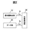
- FIG. 2 is a block diagram showing a state detection apparatus according to the embodiment of the present invention.
- FIG. 3 is a flowchart showing an operation flow of the state detection apparatus according to the embodiment of the present invention.
- FIG. 4 is a correspondence table showing the relationship between the sum of the steering angles (level) and the drowsiness level at regular intervals during driving of the vehicle.
- FIG. 5 is a graph showing, as two-dimensional data, the relationship between the total sum of steering angles (level) and the appearance frequency at regular time intervals divided by parameters of drowsiness levels 1 to 5 based on FIG.
- the state detection device 1 includes an operation amount detection unit 10 that detects an operation amount and an appearance frequency of an operation amount for each fixed time by an operator, and includes an operation amount and an appearance frequency in a plurality of state levels.
- the data unit 20 measured and associated with each other, the frequency threshold value for classifying the state level corresponding to each level, and the operation amount detected by the operation amount detection unit and the appearance frequency in a plurality of levels of operation amount
- the state detection unit 30 is configured to detect a plurality of state levels of the operator by determining the state level corresponding to each level with reference to the data unit 20.
- the operation amount detection unit 10 detects the operation amount by the operator every predetermined time at a plurality of levels.
- FIG. 1 is a graph showing the relationship between the manipulated variable (level) and the appearance frequency at regular time intervals, using levels 1 to 5 as parameters.
- the operation amount detection unit 10 detects the operation amount by measuring the appearance frequency at an arbitrary level. For example, in FIG. 1, the appearance frequency at level 1 (amount of operation per fixed time) is measured, the appearance frequency at level 2 (the amount of operation per fixed time), and the level 3 (the amount of operation per fixed time).
- the operation amount is detected at a plurality of levels, such as by measuring the appearance frequency of the.
- the operation amount detection unit 10 is, for example, a steering angle sensor that detects a steering angle as angle information.
- the operation amount detection unit 10 may integrate the steering angle at regular time intervals and output it to the state detection unit 30. Further, when the operation amount detection unit 10 is a steering angle sensor that sequentially detects the steering angle, the operation amount detection is performed by integrating the steering angle at regular intervals within the state detection unit 30. Also good.
- the data unit 20 is obtained in advance as the two-dimensional data SD for each level, with respect to the relationship between the operation amount for every fixed time and the appearance frequency. For example, it is stored in a table format by a combination of (operation amount, appearance frequency, level).
- the data unit 20 is configured so that it can be referred to from the state detection unit 30 as needed. As shown in FIG. 2, the data unit 20 may be stored in an external storage unit of the state detection unit 30 so that it can be referred to, or may be stored in an internal memory of the state detection unit 30. .
- the state detection unit 30 includes, for example, a CPU (Central Processing Unit) that performs operations and processing on acquired data according to a stored program, a RAM (Random Access Memory) that is a semiconductor memory, a ROM (Read Only Memory), and the like. It is a microcomputer configured.
- the ROM stores, for example, a program for operating the state detection unit 30, a frequency threshold value for level determination, and the like.
- the RAM is used as a storage area for temporarily storing calculation results and the like.
- FIG. 3 is a flowchart showing an operation flow of the state detection apparatus according to the embodiment of the present invention. Hereinafter, based on this flowchart, operation
- the state detection device 1 according to the present embodiment detects a plurality of state levels. Here, the case where the state levels at four levels of level 1, level 2, level 3, and level 4 are detected. explain.
- State detection unit 30 measures the frequency of occurrence H 1 at level 1 (Step1). That is, the state detection unit 30 detects the appearance frequency H 1 at the level 1 (the operation amount per fixed time of the level 1) based on the signal H 1 input from the operation amount detection unit 10.
- the state detection unit 30, the appearance frequency H 1 determines whether exceeds the frequency threshold Th1 (Step2).
- the frequency threshold Th ⁇ b> 1 is set to be between the appearance frequencies in level 5 and level 4 in level 1.
- level 5 and level 4 are classified.
- Step3 the appearance frequency H 1 exceeds the frequency threshold Th1 If not, the process proceeds to Step 4 (Step 2: No).
- the state detection unit 30 determines that the level is 5 (Step 3).
- State detection unit 30 measures the frequency of occurrence of H 2 at a level 2 (Step4). That is, the state detection unit 30 detects the appearance frequency H 2 at the level 2 (the operation amount per fixed time of the level 2) based on the signal H 2 input from the operation amount detection unit 10.
- the frequency threshold Th ⁇ b> 2 is set to be between the appearance frequencies in the level 4 and the level 3 in the level 2. Thus, level 4 and level 3 are classified.
- Step6 the occurrence frequency H 2 exceeds the frequency threshold Th2
- Step 7 the process proceeds to Step 7 (Step 5: No).
- the state detection unit 30 determines that the level is 4 (Step 6).
- State detection unit 30 measures the frequency of occurrence H 3 at levels 3 (Step7). That is, the state detection unit 30 detects the appearance frequency H 3 at the level 3 (the operation amount per fixed time of the level 3) based on the signal H 3 input from the operation amount detection unit 10.
- the state detection unit 30, the appearance frequency H 3 determines whether exceeds the frequency threshold Th3 (Step8).
- the frequency threshold Th3 is set to be between the appearance frequencies in the level 3 and the level 2 in the level 3. Thus, level 3 and level 2 are classified. If the appearance frequency H3 exceeds the frequency threshold Th3 with reference to the two-dimensional data SD obtained from the data unit 20, the process proceeds to Step 9 (Step 8: Yes), and the appearance frequency H3 does not exceed the frequency threshold Th3. In this case, the process proceeds to Step 10 (Step 8: No).
- the state detection unit 30 determines level 3 (Step 9).
- State detection unit 30 measures the frequency of occurrence H 4 at level 4 (Step10). That is, the state detection unit 30 detects the appearance frequency H 4 at the level 4 (the operation amount per fixed time of the level 4) based on the signal H 4 input from the operation amount detection unit 10.
- the state detection unit 30, the appearance frequency H 4 to determine whether it exceeds a frequency threshold Th4 (Step11).
- the frequency threshold Th4 is set to be between the appearance frequencies in the level 2 and the level 1 in the level 4. Thus, level 2 and level 1 are classified.
- the process proceeds to Step12 (Step11: Yes)
- the appearance frequency H 4 exceeds the frequency threshold Th4 If not, the process proceeds to Step 13 (Step 11: No).
- the state detection unit 30 determines level 2 (Step 12).
- the state detection unit 30 determines that the level is 1 (Step 13).
- the operation as described above it is possible to detect a plurality of state levels by determining and classifying a plurality of levels by using a frequency threshold value for each level in a plurality of levels.
- the above determination procedure is an example, and for example, determination can be made in the order of levels 1 and 2 to level 5. Further, the determination of each level is facilitated by determining where the interval between the levels to be classified is large, and the determination accuracy is improved. Further, determination accuracy can be improved by performing determination at a certain level at a plurality of levels.
- FIG. 4 is a correspondence table showing the relationship between the sum of the steering angles (level) and the drowsiness level at regular intervals during driving of the vehicle.
- FIG. 4 shows from the top as sleepiness level 5 (very sleepy), sleepiness level 4 (sleepy), sleepiness level 3 (slightly sleepy), sleepiness level 2 (not sleepy), and sleepiness level 1 (not sleepy at all).
- It is a distribution diagram of the integrated amount of steering angle change for each drowsiness level, summarizing the measurement results in which the steering angle total for a certain time is plotted in the right direction.
- FIG. 5 is a graph showing the relationship between the rudder angle sum (level) and the appearance frequency at regular intervals divided by parameters of drowsiness levels 1 to 5 based on FIG.
- the appearance frequency of the steering angle sum 500 (deg) or more is 18% or more within a certain time, it can be determined that the sleepiness level 4 (sleepy) or more.
- region R shown by hatching in FIG. 5 is an area
- a desired level of sleepiness can be classified by selecting an appropriate level and making a determination using, for example, the frequency threshold extracted from FIG. This makes it possible to detect the drowsiness level of the vehicle driver (for example, a stepped level from being quite sleepy to not sleeping at all).
- the state detection device 1 includes an operation amount detection unit 10 that detects an operation amount and an appearance frequency of an operation amount per fixed time by an operator, and an operation amount and an appearance frequency in a plurality of states.
- the data unit 20 measured and associated for each level, the frequency threshold for classifying the state level corresponding to each level in a plurality of levels of operation amount, the operation amount detected by the operation amount detection unit, and the appearance frequency
- the state detection unit 30 is configured to detect a plurality of state levels of the operator by determining the state level corresponding to each level with reference to the data unit 20.
- the state detection apparatus 1 which concerns on this Embodiment is applicable to the drowsiness level state detection apparatus which detects the drowsiness level of the driver
- the driver can drive the vehicle. It becomes possible to detect the drowsiness level in the state of being. For example, by using the frequency threshold extracted from FIG. 4, a desired sleepiness level can be classified. This makes it possible to detect the drowsiness level of the vehicle driver (for example, a stepped level from being quite sleepy to not sleeping at all).
Landscapes
- Health & Medical Sciences (AREA)
- Life Sciences & Earth Sciences (AREA)
- Physics & Mathematics (AREA)
- Engineering & Computer Science (AREA)
- Biophysics (AREA)
- Heart & Thoracic Surgery (AREA)
- Educational Technology (AREA)
- Hospice & Palliative Care (AREA)
- Psychiatry (AREA)
- Psychology (AREA)
- Social Psychology (AREA)
- Child & Adolescent Psychology (AREA)
- General Physics & Mathematics (AREA)
- Pathology (AREA)
- Biomedical Technology (AREA)
- Developmental Disabilities (AREA)
- Medical Informatics (AREA)
- Molecular Biology (AREA)
- Surgery (AREA)
- Animal Behavior & Ethology (AREA)
- General Health & Medical Sciences (AREA)
- Public Health (AREA)
- Veterinary Medicine (AREA)
- Measurement Of The Respiration, Hearing Ability, Form, And Blood Characteristics Of Living Organisms (AREA)
- Auxiliary Drives, Propulsion Controls, And Safety Devices (AREA)
- Traffic Control Systems (AREA)
Abstract
状態検知装置は、操作者による一定時間毎の操作量と操作量の出現頻度を検出する操作量検出部10と、操作量と出現頻度とを複数の状態レベル毎に測定して対応付けしたデータ部20と、操作量の複数水準において、各水準に対応して状態レベルを区分する頻度閾値と、操作量検出部により検出される操作量と出現頻度とから、データ部20を参照して各水準に対応する状態レベルを判定することにより、操作者の複数の状態レベルを検知する状態検知部30と、を有する。
Description
本出願は、日本国特許出願2017-008820号の優先権を主張するものであり、日本国特許出願2017-008820号の全内容を本出願に参照により援用する。
本発明は、状態検知装置に関する。
ドライバーの疲労の度合いを正確に判定することが出来る様な疲労判定システム及び疲労判定方法に関する状態検知装置が知られている(例えば、特許文献1参照)。
この疲労判定システムは、ドライバーの姿勢の変動を検出するユニットと、該ユニットで検出された姿勢変動の出現頻度からドライバーが疲労しているか否かを判定するユニットとを有し、ドライバーの姿勢変化の変動を検出するユニットは、ドライバーシートに左右一対設けられた圧力センサを備え、判定するユニットは、左右の圧力センサの検出結果の差(L-R)、和(L+R)、検出結果の変化量の差(dL-dR)の各々の標準偏差を求め、差(L-R)、和(L+R)、変化量の差(dL-dR)の各々について標準偏差の整数倍(例えば、3倍)よりも大きい値を異常値と定義し、異常値が一定時間当たりに出現した回数をカウントし、差(L-R)の異常値が出現した回数から、和(L+R)の異常値が出現した回数と、変化量の差(dL-dR)の異常値が出現した回数を減算し、減算結果が「正」の値をとり、且つ、増加する傾向がある場合には、ドライバーが疲労していると判定する機能を有して構成されている。
この状態検知装置によれば、ドライバーが首や腕、肩を回したり、座る位置を変えたりする等、その姿勢を変動するか否かを検出して、その出現頻度からドライバーが疲労しているか否かを正確に判定することが出来るとされている。
特許文献1に開示された状態検知装置は、判定したい水準(一定時間当たりの姿勢変動)が複数ある場合、1つの頻度閾値(異常値)による出現頻度の判定では区分ができない。
本発明の目的は、複数水準での状態を検知することができる状態検知装置を提供することにある。
本発明の一実施形態による状態検知装置は、下記[1]~[6]の構成を有する。
[1]操作者による一定時間毎の操作量と前記操作量の出現頻度を検出する操作量検出部と、前記操作量と前記出現頻度とを複数の状態レベル毎に測定して対応付けしたデータ部と、前記操作量の複数水準において、各水準に対応して前記状態レベルを区分する頻度閾値と、前記操作量検出部により検出される前記操作量と前記出現頻度とから、前記データ部を参照して前記各水準に対応する状態レベルを判定することにより、前記操作者の複数の状態レベルを検知する状態検知部と、を有する、状態検知装置。
[2]前記操作者は車両の運転者であり、前記操作量はステアリングの一定時間毎の舵角操舵量、前記出現頻度は前記舵角操舵量の出現頻度である、上記[1]に記載の状態検知装置。
[3]前記状態レベルは、前記操作者の前記車両の運転時における眠気レベルである、上記[2]に記載の状態検知装置。
[4]前記眠気レベルは、眠さの状態レベルが複数段階に区分されている、上記[3]に記載の状態検知装置。
[5]前記操作量検出部は、前記舵角操舵量を角度情報として検出する舵角センサであり、一定時間毎の前記舵角操舵量を積算する、上記[2]に記載の状態検知装置。
[6]前記状態検知部は、前記各水準として、区分したい前記状態レベル間の間隔が大きい水準で前記各水準に対応する前記状態レベルを判定する、上記[1]に記載の状態検知装置。
本発明の一実施形態によれば、複数水準での状態を検知することができる状態検知装置を提供することができる。
(本発明の実施の形態)
本発明の実施の形態に係る状態検知装置1は、操作者による一定時間毎の操作量と操作量の出現頻度を検出する操作量検出部10と、操作量と出現頻度とを複数の状態レベル毎に測定して対応付けしたデータ部20と、操作量の複数水準において、各水準に対応して状態レベルを区分する頻度閾値と、操作量検出部により検出される操作量と出現頻度とから、データ部20を参照して各水準に対応する状態レベルを判定することにより、操作者の複数の状態レベルを検知する状態検知部30と、を有して構成されている。
本発明の実施の形態に係る状態検知装置1は、操作者による一定時間毎の操作量と操作量の出現頻度を検出する操作量検出部10と、操作量と出現頻度とを複数の状態レベル毎に測定して対応付けしたデータ部20と、操作量の複数水準において、各水準に対応して状態レベルを区分する頻度閾値と、操作量検出部により検出される操作量と出現頻度とから、データ部20を参照して各水準に対応する状態レベルを判定することにより、操作者の複数の状態レベルを検知する状態検知部30と、を有して構成されている。
(操作量検出部10)
操作量検出部10は、操作者による一定時間毎の操作量を複数水準で検出する。ここで、図1は、一定時間毎の操作量(水準)と出現頻度の関係をレベル1から5をパラメータとして示すグラフである。操作量検出部10は、図1において、任意の水準における出現頻度を測定することにより操作量検出を行なう。例えば、図1において、水準1(一定時間毎の操作量)での出現頻度を測定、水準2(一定時間毎の操作量)での出現頻度を測定、水準3(一定時間毎の操作量)での出現頻度を測定する等の、複数の水準で操作量検出を行なう。
操作量検出部10は、操作者による一定時間毎の操作量を複数水準で検出する。ここで、図1は、一定時間毎の操作量(水準)と出現頻度の関係をレベル1から5をパラメータとして示すグラフである。操作量検出部10は、図1において、任意の水準における出現頻度を測定することにより操作量検出を行なう。例えば、図1において、水準1(一定時間毎の操作量)での出現頻度を測定、水準2(一定時間毎の操作量)での出現頻度を測定、水準3(一定時間毎の操作量)での出現頻度を測定する等の、複数の水準で操作量検出を行なう。
この操作量検出部10は、車両であれば、例えば、操舵角を角度情報として検出する舵角センサである。また、操作量検出部10は、一定時間毎の操舵角を積算して、状態検知部30へ出力してもよい。また、操作量検出部10が逐次操舵角を検出する舵角センサである場合は、状態検知部30内部で一定の時間毎に操舵角を積算処理することにより操作量検出を実行するようにしてもよい。
(データ部20)
データ部20は、予め一定時間毎の操作量と出現頻度との関係を、レベル毎に2次元データSDとして求められたものである。例えば、(操作量、出現頻度、レベル)の組み合わせによりテーブル形式により記憶される。このデータ部20は、状態検知部30から必要に応じて随時参照できるように構成されている。データ部20は、図2に示すように、状態検知部30の外部記憶部に参照可能に記憶されていてもよく、また、状態検知部30の内部メモリに記憶される形態であってもよい。
データ部20は、予め一定時間毎の操作量と出現頻度との関係を、レベル毎に2次元データSDとして求められたものである。例えば、(操作量、出現頻度、レベル)の組み合わせによりテーブル形式により記憶される。このデータ部20は、状態検知部30から必要に応じて随時参照できるように構成されている。データ部20は、図2に示すように、状態検知部30の外部記憶部に参照可能に記憶されていてもよく、また、状態検知部30の内部メモリに記憶される形態であってもよい。
(状態検知部30)
状態検知部30は、例えば、記憶されたプログラムに従って、取得したデータに演算、加工等を行うCPU(Central Processing Unit)、半導体メモリであるRAM(Random Access Memory)及びROM(Read Only Memory)などから構成されるマイクロコンピュータである。ROMには、例えば、状態検知部30が動作するためのプログラム、レベル判定のための頻度閾値等が格納されている。RAMは、例えば、一時的に演算結果などを格納する記憶領域として用いられる。
状態検知部30は、例えば、記憶されたプログラムに従って、取得したデータに演算、加工等を行うCPU(Central Processing Unit)、半導体メモリであるRAM(Random Access Memory)及びROM(Read Only Memory)などから構成されるマイクロコンピュータである。ROMには、例えば、状態検知部30が動作するためのプログラム、レベル判定のための頻度閾値等が格納されている。RAMは、例えば、一時的に演算結果などを格納する記憶領域として用いられる。
(状態検知装置1の動作)
図3は、本発明の実施の形態に係る状態検知装置の動作フローを示すフローチャートである。以下、このフローチャートに基づいて、状態検知装置1の動作を説明する。本実施の形態に係る状態検知装置1は、複数の状態レベルを検知するものであるが、ここでは、水準1、水準2、水準3、水準4の4つの水準における状態レベルを検知する場合を説明する。
図3は、本発明の実施の形態に係る状態検知装置の動作フローを示すフローチャートである。以下、このフローチャートに基づいて、状態検知装置1の動作を説明する。本実施の形態に係る状態検知装置1は、複数の状態レベルを検知するものであるが、ここでは、水準1、水準2、水準3、水準4の4つの水準における状態レベルを検知する場合を説明する。
状態検知部30は、水準1での出現頻度H1を測定する(Step1)。すなわち、状態検知部30は、操作量検出部10から入力される信号H1に基づいて、水準1(水準1の一定時間毎の操作量)の時の出現頻度H1を検出する。
次に、状態検知部30は、出現頻度H1が頻度閾値Th1を超えているかどうかを判断する(Step2)。ここで、頻度閾値Th1は、水準1において、レベル5とレベル4における出現頻度間になるように設定されている。これにより、レベル5とレベル4の区分をする。データ部20から得られる2次元データSDを参照して、出現頻度H1が頻度閾値Th1を超えている場合は、Step3へ進み(Step2:Yes)、出現頻度H1が頻度閾値Th1を超えていない場合は、Step4へ進む(Step2:No)。
状態検知部30は、レベル5と判定する(Step3)。
状態検知部30は、水準2での出現頻度H2を測定する(Step4)。すなわち、状態検知部30は、操作量検出部10から入力される信号H2に基づいて、水準2(水準2の一定時間毎の操作量)の時の出現頻度H2を検出する。
次に、状態検知部30は、出現頻度H2が頻度閾値Th2を超えているかどうかを判断する(Step5)。ここで、頻度閾値Th2は、水準2において、レベル4とレベル3における出現頻度間になるように設定されている。これにより、レベル4とレベル3の区分をする。データ部20から得られる2次元データSDを参照して、出現頻度H2が頻度閾値Th2を超えている場合は、Step6へ進み(Step5:Yes)、出現頻度H2が頻度閾値Th2を超えていない場合は、Step7へ進む(Step5:No)。
状態検知部30は、レベル4と判定する(Step6)。
状態検知部30は、水準3での出現頻度H3を測定する(Step7)。すなわち、状態検知部30は、操作量検出部10から入力される信号H3に基づいて、水準3(水準3の一定時間毎の操作量)の時の出現頻度H3を検出する。
次に、状態検知部30は、出現頻度H3が頻度閾値Th3を超えているかどうかを判断する(Step8)。ここで、頻度閾値Th3は、水準3において、レベル3とレベル2における出現頻度間になるように設定されている。これにより、レベル3とレベル2の区分をする。データ部20から得られる2次元データSDを参照して、出現頻度H3が頻度閾値Th3を超えている場合は、Step9へ進み(Step8:Yes)、出現頻度H3が頻度閾値Th3を超えていない場合は、Step10へ進む(Step8:No)。
状態検知部30は、レベル3と判定する(Step9)。
状態検知部30は、水準4での出現頻度H4を測定する(Step10)。すなわち、状態検知部30は、操作量検出部10から入力される信号H4に基づいて、水準4(水準4の一定時間毎の操作量)の時の出現頻度H4を検出する。
次に、状態検知部30は、出現頻度H4が頻度閾値Th4を超えているかどうかを判断する(Step11)。ここで、頻度閾値Th4は、水準4において、レベル2とレベル1における出現頻度間になるように設定されている。これにより、レベル2とレベル1の区分をする。データ部20から得られる2次元データSDを参照して、出現頻度H4が頻度閾値Th4を超えている場合は、Step12へ進み(Step11:Yes)、出現頻度H4が頻度閾値Th4を超えていない場合は、Step13へ進む(Step11:No)。
状態検知部30は、レベル2と判定する(Step12)。
状態検知部30は、レベル1と判定する(Step13)。
以上のような動作により、複数水準において水準毎の頻度閾値を用いることで複数のレベルを判定して区分することにより、複数の状態レベルを検知することができる。なお、上記の判断手順は一例であって、例えば、レベル1、2からレベル5の順に判定することもできる。また、各レベルの判定は、区分したいレベル間の間隔が大きい水準のところで判定することにより判定が容易となり、判定の精度が向上する。また、あるレベルの判定を、複数の水準において行なうことにより、判定精度を向上させることも可能となる。
(眠気レベル状態検知装置への適用)
上記説明した状態検知装置1を車両の運転者の眠気レベルを検知する眠気レベル状態検知装置へ適用する場合について説明する。
上記説明した状態検知装置1を車両の運転者の眠気レベルを検知する眠気レベル状態検知装置へ適用する場合について説明する。
図4は、車両の運転時における一定時間毎の舵角総和(水準)と眠気レベルの関係を示す対応表である。図4は、上から、眠気レベル5(かなり眠い)、眠気レベル4(眠い)、眠気レベル3(少し眠い)、眠気レベル2(眠くない)、眠気レベル1(まったく眠くない)として、それぞれ、右方向に一定時間における舵角総和をプロットした測定結果をまとめた、眠気レベル毎の舵角変化積算量の分布図である。
図4において、舵角総和がX(deg)の場合の水準Xにおいて、図4中に示した出現頻度25.8%(レベル5)、24.4%(レベル4)、13.9%(レベル3)、9.6%(レベル2)、7.1%(レベル1)は眠気レベルとの相関が認められる。
図5は、図4に基づいて、一定時間毎の舵角総和(水準)と出現頻度との関係を眠気レベル1~5のパラメータで区分して示したグラフである。図5において、舵角総和500(deg)以上の出現頻度が一定時間内で18%以上の場合、眠気レベル4(眠い)以上と判定することができる。
なお、図5にハッチングで示した領域Rは、例えば、眠気レベル4と眠気レベル3を区分するのに適した領域である。このような領域において、適切な水準を選択して、例えば図4から抽出した頻度閾値を用いて判定することにより、所望の眠気レベルを区分することができる。これにより、車両の運転者の眠気レベル(例えば、かなり眠いからまったく眠くないまでの段階的レベル)の検知が可能となる。
(本発明の実施の形態の効果)
本発明の実施の形態に係る状態検知装置によれば、以下のような効果を有する。
(1)本実施の形態に係る状態検知装置1は、操作者による一定時間毎の操作量と操作量の出現頻度を検出する操作量検出部10と、操作量と出現頻度とを複数の状態レベル毎に測定して対応付けしたデータ部20と、操作量の複数水準において、各水準に対応して状態レベルを区分する頻度閾値と、操作量検出部により検出される操作量と出現頻度とから、データ部20を参照して各水準に対応する状態レベルを判定することにより、操作者の複数の状態レベルを検知する状態検知部30と、を有して構成されている。このような構成により、複数水準において水準毎の頻度閾値を用いることで複数のレベルを判定して区分することにより、複数の状態レベルを検知することができる。また、各レベルの判定は、区分したいレベル間の間隔が大きい水準のところで判定することにより判定が容易となり、判定の精度が向上する。また、あるレベルの判定を、複数の水準において行なうことにより、判定精度を向上させることも可能となる。
(2)また、本実施の形態に係る状態検知装置1を車両の運転者の眠気レベルを検知する眠気レベル状態検知装置へ適用することができる。眠気レベルを複数段階のパラメータとし、一定時間毎の操作量を一定時間舵角総和(deg)として出現頻度と2次元データしたものをデータ部20とすることにより、運転者が車両を運転している状態での眠気レベルを検知することが可能となる。例えば図4から抽出した頻度閾値を用いて判定することにより、所望の眠気レベルを区分することができる。これにより、車両の運転者の眠気レベル(例えば、かなり眠いからまったく眠くないまでの段階的レベル)の検知が可能となる。
本発明の実施の形態に係る状態検知装置によれば、以下のような効果を有する。
(1)本実施の形態に係る状態検知装置1は、操作者による一定時間毎の操作量と操作量の出現頻度を検出する操作量検出部10と、操作量と出現頻度とを複数の状態レベル毎に測定して対応付けしたデータ部20と、操作量の複数水準において、各水準に対応して状態レベルを区分する頻度閾値と、操作量検出部により検出される操作量と出現頻度とから、データ部20を参照して各水準に対応する状態レベルを判定することにより、操作者の複数の状態レベルを検知する状態検知部30と、を有して構成されている。このような構成により、複数水準において水準毎の頻度閾値を用いることで複数のレベルを判定して区分することにより、複数の状態レベルを検知することができる。また、各レベルの判定は、区分したいレベル間の間隔が大きい水準のところで判定することにより判定が容易となり、判定の精度が向上する。また、あるレベルの判定を、複数の水準において行なうことにより、判定精度を向上させることも可能となる。
(2)また、本実施の形態に係る状態検知装置1を車両の運転者の眠気レベルを検知する眠気レベル状態検知装置へ適用することができる。眠気レベルを複数段階のパラメータとし、一定時間毎の操作量を一定時間舵角総和(deg)として出現頻度と2次元データしたものをデータ部20とすることにより、運転者が車両を運転している状態での眠気レベルを検知することが可能となる。例えば図4から抽出した頻度閾値を用いて判定することにより、所望の眠気レベルを区分することができる。これにより、車両の運転者の眠気レベル(例えば、かなり眠いからまったく眠くないまでの段階的レベル)の検知が可能となる。
以上、本発明のいくつかの実施の形態を説明したが、これらの実施の形態は、一例に過ぎず、請求の範囲に係る発明を限定するものではない。これら新規な実施の形態は、その他の様々な形態で実施されることが可能であり、本発明の要旨を逸脱しない範囲で、種々の省略、置き換え、変更等を行うことができる。
また、これら実施の形態の中で説明した特徴の組合せの全てが発明の課題を解決するための手段に必須であるとは限らない。さらに、これら実施の形態は、発明の範囲及び要旨に含まれるとともに、請求の範囲に記載された発明とその均等の範囲に含まれる。
1 状態検知装置
10 操作量検出部
20 データ部
30 状態検知部
10 操作量検出部
20 データ部
30 状態検知部
Claims (6)
- 操作者による一定時間毎の操作量と前記操作量の出現頻度を検出する操作量検出部と、
前記操作量と前記出現頻度とを複数の状態レベル毎に測定して対応付けしたデータ部と、
前記操作量の複数水準において、各水準に対応して前記状態レベルを区分する頻度閾値と、前記操作量検出部により検出される前記操作量と前記出現頻度とから、前記データ部を参照して前記各水準に対応する状態レベルを判定することにより、前記操作者の複数の状態レベルを検知する状態検知部と、
を有する、状態検知装置。 - 前記操作者は車両の運転者であり、前記操作量はステアリングの一定時間毎の舵角操舵量、前記出現頻度は前記舵角操舵量の出現頻度である、請求項1に記載の状態検知装置。
- 前記状態レベルは、前記操作者の前記車両の運転時における眠気レベルである、請求項2に記載の状態検知装置。
- 前記眠気レベルは、眠さの状態レベルが複数段階に区分されている、請求項3に記載の状態検知装置。
- 前記操作量検出部は、前記舵角操舵量を角度情報として検出する舵角センサであり、一定時間毎の前記舵角操舵量を積算する、請求項2に記載の状態検知装置。
- 前記状態検知部は、前記各水準として、区分したい前記状態レベル間の間隔が大きい水準で前記各水準に対応する前記状態レベルを判定する、請求項1に記載の状態検知装置。
Applications Claiming Priority (2)
| Application Number | Priority Date | Filing Date | Title |
|---|---|---|---|
| JP2017-008820 | 2017-01-20 | ||
| JP2017008820A JP2018116650A (ja) | 2017-01-20 | 2017-01-20 | 状態検知装置 |
Publications (1)
| Publication Number | Publication Date |
|---|---|
| WO2018135338A1 true WO2018135338A1 (ja) | 2018-07-26 |
Family
ID=62908157
Family Applications (1)
| Application Number | Title | Priority Date | Filing Date |
|---|---|---|---|
| PCT/JP2018/000214 Ceased WO2018135338A1 (ja) | 2017-01-20 | 2018-01-09 | 状態検知装置 |
Country Status (2)
| Country | Link |
|---|---|
| JP (1) | JP2018116650A (ja) |
| WO (1) | WO2018135338A1 (ja) |
Families Citing this family (1)
| Publication number | Priority date | Publication date | Assignee | Title |
|---|---|---|---|---|
| JP7375691B2 (ja) | 2020-07-01 | 2023-11-08 | トヨタ自動車株式会社 | 眠気兆候通知システム |
Citations (3)
| Publication number | Priority date | Publication date | Assignee | Title |
|---|---|---|---|---|
| JP2008221967A (ja) * | 2007-03-12 | 2008-09-25 | Honda Motor Co Ltd | ステアリング保持状態判定装置、ドライバ覚醒度推定装置および適正進路維持装置 |
| JP2014123287A (ja) * | 2012-12-21 | 2014-07-03 | Daimler Ag | 居眠り運転警報装置および居眠り運転警報方法 |
| JP2016034810A (ja) * | 2014-08-04 | 2016-03-17 | 株式会社デンソーアイティーラボラトリ | 車両制御装置 |
-
2017
- 2017-01-20 JP JP2017008820A patent/JP2018116650A/ja active Pending
-
2018
- 2018-01-09 WO PCT/JP2018/000214 patent/WO2018135338A1/ja not_active Ceased
Patent Citations (3)
| Publication number | Priority date | Publication date | Assignee | Title |
|---|---|---|---|---|
| JP2008221967A (ja) * | 2007-03-12 | 2008-09-25 | Honda Motor Co Ltd | ステアリング保持状態判定装置、ドライバ覚醒度推定装置および適正進路維持装置 |
| JP2014123287A (ja) * | 2012-12-21 | 2014-07-03 | Daimler Ag | 居眠り運転警報装置および居眠り運転警報方法 |
| JP2016034810A (ja) * | 2014-08-04 | 2016-03-17 | 株式会社デンソーアイティーラボラトリ | 車両制御装置 |
Also Published As
| Publication number | Publication date |
|---|---|
| JP2018116650A (ja) | 2018-07-26 |
Similar Documents
| Publication | Publication Date | Title |
|---|---|---|
| US10005415B2 (en) | Determination apparatus and method for occupant | |
| CN109278756B (zh) | 识别和表征驾驶行为的方法、控制单元和机动车 | |
| WO2020112213A3 (en) | Deep neural network processing for sensor blindness detection in autonomous machine applications | |
| CN106133751A (zh) | 用于运行车辆的方法和设备 | |
| US9625354B2 (en) | Detecting occurrence of abnormality | |
| JP2015152938A5 (ja) | ||
| WO2019179840A3 (de) | Sensoranordnung für ein fahrzeug und verfahren zur überwachung eines sensors | |
| WO2019243114A3 (en) | Method and computer system for determining polymeric product properties | |
| JP2009227034A (ja) | タイヤ空気圧低下検出方法及び装置、並びにタイヤ減圧判定のプログラム | |
| JP5510611B2 (ja) | ドライバ状態判定装置 | |
| US10278891B2 (en) | Automatic skin type detecting electronic device and method for skin care | |
| KR102470306B1 (ko) | 타이어 압력 추정 장치 및 그 추정 방법 | |
| US10980463B2 (en) | Driver's tension level determining apparatus and driver's tension level determining method | |
| KR101556598B1 (ko) | 주요 픽셀 정보에 기반한 물체 검출 장치 및 그 방법 | |
| US20180217565A1 (en) | Pid control device, pid control method, and pid control program | |
| WO2018135338A1 (ja) | 状態検知装置 | |
| CN106108922A (zh) | 瞌睡探测装置 | |
| JP7077781B2 (ja) | 車両の挙動判定方法 | |
| CN104648405A (zh) | 用于探测车辆驾驶员的注意力状态的方法 | |
| JP2012212379A (ja) | 運転者状態検出システム及び運転者状態検出方法 | |
| JP6409375B2 (ja) | パラメータ分類装置 | |
| JP2018151902A5 (ja) | ||
| US9983004B2 (en) | Temperature characteristic correction device, temperature characteristic correction formula determination method, electronic apparatus, and control circuit | |
| JP2011096086A (ja) | 運転評価装置 | |
| TWI532621B (zh) | Fatigue driving judgment system and its method |
Legal Events
| Date | Code | Title | Description |
|---|---|---|---|
| 121 | Ep: the epo has been informed by wipo that ep was designated in this application |
Ref document number: 18741838 Country of ref document: EP Kind code of ref document: A1 |
|
| NENP | Non-entry into the national phase |
Ref country code: DE |
|
| 122 | Ep: pct application non-entry in european phase |
Ref document number: 18741838 Country of ref document: EP Kind code of ref document: A1 |