WO2018135283A1 - タービン翼の冷却構造 - Google Patents
タービン翼の冷却構造 Download PDFInfo
- Publication number
- WO2018135283A1 WO2018135283A1 PCT/JP2017/047091 JP2017047091W WO2018135283A1 WO 2018135283 A1 WO2018135283 A1 WO 2018135283A1 JP 2017047091 W JP2017047091 W JP 2017047091W WO 2018135283 A1 WO2018135283 A1 WO 2018135283A1
- Authority
- WO
- WIPO (PCT)
- Prior art keywords
- cooling
- blade
- wall
- turbine
- lattice structure
- Prior art date
- Legal status (The legal status is an assumption and is not a legal conclusion. Google has not performed a legal analysis and makes no representation as to the accuracy of the status listed.)
- Ceased
Links
Images


Classifications
-
- F—MECHANICAL ENGINEERING; LIGHTING; HEATING; WEAPONS; BLASTING
- F01—MACHINES OR ENGINES IN GENERAL; ENGINE PLANTS IN GENERAL; STEAM ENGINES
- F01D—NON-POSITIVE DISPLACEMENT MACHINES OR ENGINES, e.g. STEAM TURBINES
- F01D5/00—Blades; Blade-carrying members; Heating, heat-insulating, cooling or antivibration means on the blades or the members
- F01D5/12—Blades
- F01D5/14—Form or construction
- F01D5/147—Construction, i.e. structural features, e.g. of weight-saving hollow blades
-
- F—MECHANICAL ENGINEERING; LIGHTING; HEATING; WEAPONS; BLASTING
- F01—MACHINES OR ENGINES IN GENERAL; ENGINE PLANTS IN GENERAL; STEAM ENGINES
- F01D—NON-POSITIVE DISPLACEMENT MACHINES OR ENGINES, e.g. STEAM TURBINES
- F01D5/00—Blades; Blade-carrying members; Heating, heat-insulating, cooling or antivibration means on the blades or the members
- F01D5/12—Blades
- F01D5/14—Form or construction
- F01D5/18—Hollow blades, i.e. blades with cooling or heating channels or cavities; Heating, heat-insulating or cooling means on blades
- F01D5/187—Convection cooling
-
- F—MECHANICAL ENGINEERING; LIGHTING; HEATING; WEAPONS; BLASTING
- F01—MACHINES OR ENGINES IN GENERAL; ENGINE PLANTS IN GENERAL; STEAM ENGINES
- F01D—NON-POSITIVE DISPLACEMENT MACHINES OR ENGINES, e.g. STEAM TURBINES
- F01D5/00—Blades; Blade-carrying members; Heating, heat-insulating, cooling or antivibration means on the blades or the members
- F01D5/12—Blades
- F01D5/14—Form or construction
- F01D5/18—Hollow blades, i.e. blades with cooling or heating channels or cavities; Heating, heat-insulating or cooling means on blades
-
- F—MECHANICAL ENGINEERING; LIGHTING; HEATING; WEAPONS; BLASTING
- F01—MACHINES OR ENGINES IN GENERAL; ENGINE PLANTS IN GENERAL; STEAM ENGINES
- F01D—NON-POSITIVE DISPLACEMENT MACHINES OR ENGINES, e.g. STEAM TURBINES
- F01D25/00—Component parts, details, or accessories, not provided for in, or of interest apart from, other groups
- F01D25/08—Cooling; Heating; Heat-insulation
- F01D25/12—Cooling
-
- F—MECHANICAL ENGINEERING; LIGHTING; HEATING; WEAPONS; BLASTING
- F01—MACHINES OR ENGINES IN GENERAL; ENGINE PLANTS IN GENERAL; STEAM ENGINES
- F01D—NON-POSITIVE DISPLACEMENT MACHINES OR ENGINES, e.g. STEAM TURBINES
- F01D5/00—Blades; Blade-carrying members; Heating, heat-insulating, cooling or antivibration means on the blades or the members
- F01D5/12—Blades
- F01D5/14—Form or construction
- F01D5/18—Hollow blades, i.e. blades with cooling or heating channels or cavities; Heating, heat-insulating or cooling means on blades
- F01D5/186—Film cooling
-
- F—MECHANICAL ENGINEERING; LIGHTING; HEATING; WEAPONS; BLASTING
- F01—MACHINES OR ENGINES IN GENERAL; ENGINE PLANTS IN GENERAL; STEAM ENGINES
- F01D—NON-POSITIVE DISPLACEMENT MACHINES OR ENGINES, e.g. STEAM TURBINES
- F01D5/00—Blades; Blade-carrying members; Heating, heat-insulating, cooling or antivibration means on the blades or the members
- F01D5/12—Blades
- F01D5/14—Form or construction
- F01D5/18—Hollow blades, i.e. blades with cooling or heating channels or cavities; Heating, heat-insulating or cooling means on blades
- F01D5/187—Convection cooling
- F01D5/188—Convection cooling with an insert in the blade cavity to guide the cooling fluid, e.g. forming a separation wall
-
- F—MECHANICAL ENGINEERING; LIGHTING; HEATING; WEAPONS; BLASTING
- F01—MACHINES OR ENGINES IN GENERAL; ENGINE PLANTS IN GENERAL; STEAM ENGINES
- F01D—NON-POSITIVE DISPLACEMENT MACHINES OR ENGINES, e.g. STEAM TURBINES
- F01D9/00—Stators
- F01D9/02—Nozzles; Nozzle boxes; Stator blades; Guide conduits, e.g. individual nozzles
-
- F—MECHANICAL ENGINEERING; LIGHTING; HEATING; WEAPONS; BLASTING
- F01—MACHINES OR ENGINES IN GENERAL; ENGINE PLANTS IN GENERAL; STEAM ENGINES
- F01D—NON-POSITIVE DISPLACEMENT MACHINES OR ENGINES, e.g. STEAM TURBINES
- F01D9/00—Stators
- F01D9/06—Fluid supply conduits to nozzles or the like
- F01D9/065—Fluid supply or removal conduits traversing the working fluid flow, e.g. for lubrication-, cooling-, or sealing fluids
-
- F—MECHANICAL ENGINEERING; LIGHTING; HEATING; WEAPONS; BLASTING
- F02—COMBUSTION ENGINES; HOT-GAS OR COMBUSTION-PRODUCT ENGINE PLANTS
- F02C—GAS-TURBINE PLANTS; AIR INTAKES FOR JET-PROPULSION PLANTS; CONTROLLING FUEL SUPPLY IN AIR-BREATHING JET-PROPULSION PLANTS
- F02C7/00—Features, components parts, details or accessories, not provided for in, or of interest apart form groups F02C1/00 - F02C6/00; Air intakes for jet-propulsion plants
- F02C7/12—Cooling of plants
- F02C7/16—Cooling of plants characterised by cooling medium
- F02C7/18—Cooling of plants characterised by cooling medium the medium being gaseous, e.g. air
-
- F—MECHANICAL ENGINEERING; LIGHTING; HEATING; WEAPONS; BLASTING
- F05—INDEXING SCHEMES RELATING TO ENGINES OR PUMPS IN VARIOUS SUBCLASSES OF CLASSES F01-F04
- F05D—INDEXING SCHEME FOR ASPECTS RELATING TO NON-POSITIVE-DISPLACEMENT MACHINES OR ENGINES, GAS-TURBINES OR JET-PROPULSION PLANTS
- F05D2260/00—Function
- F05D2260/20—Heat transfer, e.g. cooling
- F05D2260/201—Heat transfer, e.g. cooling by impingement of a fluid
-
- F—MECHANICAL ENGINEERING; LIGHTING; HEATING; WEAPONS; BLASTING
- F05—INDEXING SCHEMES RELATING TO ENGINES OR PUMPS IN VARIOUS SUBCLASSES OF CLASSES F01-F04
- F05D—INDEXING SCHEME FOR ASPECTS RELATING TO NON-POSITIVE-DISPLACEMENT MACHINES OR ENGINES, GAS-TURBINES OR JET-PROPULSION PLANTS
- F05D2260/00—Function
- F05D2260/20—Heat transfer, e.g. cooling
- F05D2260/221—Improvement of heat transfer
- F05D2260/2214—Improvement of heat transfer by increasing the heat transfer surface
- F05D2260/22141—Improvement of heat transfer by increasing the heat transfer surface using fins or ribs
Definitions
- the present invention relates to a structure for cooling a stationary blade and a moving blade in a turbine of a gas turbine engine.
- the turbine constituting the gas turbine engine is disposed downstream of the combustor and is supplied with high-temperature gas combusted in the combustor, so that it is exposed to high temperatures during operation of the gas turbine engine. Therefore, it is necessary to cool the stationary blades and the moving blades of the turbine.
- As a structure for cooling such turbine blades it is known that a part of air compressed by a compressor is introduced into a cooling passage formed in the blades, and the turbine blades are cooled by using compressed air as a cooling medium. (For example, refer to Patent Document 1).
- Patent Document 2 when the film cooling of the trailing edge of the wing is combined with the lattice structure, a strong vortex flowing out from the lattice structure is discharged to the exposed wall surface and the high temperature flowing outside Get involved in the gas. As a result, it was difficult to obtain a sufficient cooling effect by film cooling.
- an object of the present invention is to solve the above-described problems by cooling the inside of the turbine blade with a lattice structure with high efficiency and effectively cooling the trailing edge of the turbine blade by film cooling.
- the object of the present invention is to provide a cooling structure that can cool the battery efficiently.
- a turbine blade cooling structure is a structure for cooling a turbine blade of a turbine driven by high-temperature gas, and has a concave shape with respect to the flow path of the high-temperature gas.
- a first rib set comprising a plurality of first ribs provided on the wall surface of the first blade wall and a plurality of second ribs provided on the wall surface of the second blade wall facing the cooling passage.
- the refrigerant outlet and the second wall to the outside of the refrigerant outlet.
- An exposed wall portion that is a portion formed and a portion of the cooling passage from an outlet of the lattice structure to the refrigerant discharge port, the wall surface of the first wall and the wall surface of the second wall Includes a flat surface portion formed as a flat surface.
- the cooling medium discharged from the lattice structure as a vortex flow is rectified into a flow in a uniform direction along the wall surface in the process of flowing through the flat surface portion, and then discharged from the refrigerant discharge port to the exposed wall portion. Is done. Thereby, mixing of a high temperature gas and a cooling medium is suppressed in an exposed wall part, and sufficient film cooling effect is acquired. Therefore, the cooling within the turbine blade by the lattice structure and the film cooling at the trailing edge of the turbine blade can be achieved with high efficiency, so that the cooling efficiency of the entire turbine blade can be increased.
- the length of the flat surface portion may be in the range of 1 to 5 times the height of the exit of the lattice structure. According to this configuration, it is possible to secure a sufficient distance for the vortex discharged from the lattice structure to be rectified for film cooling within a range that does not substantially affect the cooling effect of the lattice structure. Therefore, it is possible to further increase the cooling efficiency of the entire turbine blade.
- the moving direction of the entire cooling medium is a direction along a chord of the turbine blade, and the plurality of lattice structures are arranged in the height direction of the turbine blade via the partition body. May be arranged side by side.
- the moving direction of the entire cooling medium is set as the chord direction, a flat surface portion where no lattice structure exists is formed in a narrow space at the rear end portion of the turbine blade. Therefore, the cooling effect by omitting the lattice structure is reduced. Reduction is suppressed and manufacture of the turbine blade is facilitated. Further, since the exposed wall portion can be secured widely in the height direction of the turbine blade, the cooling efficiency of the entire turbine blade can be further increased.
- FIG. 3 is a longitudinal sectional view schematically showing an enlarged vicinity of a rear end portion of the turbine blade of FIG. 2. It is a figure which shows the simulation result about the relationship between the length of the flat surface part in the cooling structure which concerns on one Embodiment of this invention, and the intensity
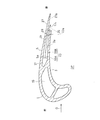
- FIG. 1 is a perspective view showing a turbine blade 1 of a turbine of a gas turbine engine to which a turbine blade cooling structure according to an embodiment of the present invention is applied.
- the turbine rotor blade 1 forms a turbine T that is driven by a hot gas G that is supplied from a combustor (not shown) and flows in the direction of the arrow.
- the turbine rotor blade 1 includes a first blade wall 3 that is concavely curved with respect to the flow path GP of the high-temperature gas G, and a second blade wall 5 that is curved convexly with respect to the flow path GP of the high-temperature gas.
- the upstream side (the left side in FIG. 1) along the flow direction of the hot gas G is referred to as the front, and the downstream side (the right side in FIG. 1) is referred to as the rear.
- the turbine blade 1 is mainly shown as an example of a turbine blade provided with a cooling structure, but the cooling structure according to the present embodiment is a turbine blade that is a turbine blade, unless specifically described. It can be similarly applied to.
- the turbine rotor blade 1 is connected to the outer periphery of the turbine disk 13 so that a large number of the turbine blades 1 are implanted in the circumferential direction to form a turbine T. .
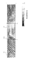
- a front cooling passage 15 extending in the blade height direction H and turning back is formed inside the front portion 1 a of the turbine rotor blade 1.
- a rear cooling passage 17 is formed in the rear portion 1 b of the turbine rotor blade 1.
- the cooling medium CL which is a part of the compressed air from the compressor, is formed in the front cooling medium introduction passage 19 and the rear cooling medium introduction passage 21 formed inside the turbine disk 13 on the radially inner side. And flows radially outward and introduced into the front cooling passage 15 and the rear cooling passage 17, respectively.
- the cooling medium CL supplied to the front cooling passage 15 is discharged to the outside from a refrigerant discharge hole (not shown) communicating with the outside of the turbine rotor blade 1.
- the cooling medium CL supplied to the rear cooling passage 17 is discharged to the outside from a refrigerant discharge port 25 described later.
- the cooling structure according to the present embodiment is provided in any range including the rear portion 1b of the turbine rotor blade 1. Also good.
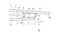
- the entire cooling medium CL flows in the rear cooling passage 17 in a direction crossing from the front to the rear.
- the flow direction of the entire cooling medium CL is referred to as a refrigerant moving direction M.
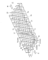
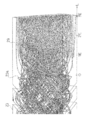
- a lattice structure 23 is provided in the rear cooling passage 17 as one element constituting a cooling structure for cooling the turbine rotor blade 1.
- the lattice structure 23 includes a plurality of ribs erected on the wall surfaces of the first blade wall 3 and the second blade wall 5 facing the rear cooling passage 17.
- the wall surface facing the rear cooling passage 17 of the first blade wall 3 is referred to as a first wall surface 3a
- the wall surface facing the rear cooling passage 17 of the second blade wall 5 is referred to as a second wall surface 5a.
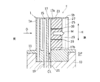
- the turbine rotor blade 1 further includes a refrigerant discharge port 25, an exposed wall portion 27, and a flat surface portion 29.
- a portion where the first blade wall 3 is notched and the wall surface of the second blade wall 5 is exposed to the outside (hot gas flow path GP) forms an exposed wall portion 27.
- the refrigerant discharge port 25 is provided at a downstream end (rear end) of the rear cooling passage 17 and discharges the cooling medium CL in the rear cooling passage 17 to the outside.
- the refrigerant discharge port 25 is formed as a gap between the first wall surface 3a and the second wall surface 5a at the location where the first blade wall 3 is cut out as described above.
- the exposed wall portion 27 is a portion formed to extend to the outside of the refrigerant discharge port 25 of the second blade wall 5. Therefore, the wall surface 27a facing the first blade wall 3 side of the exposed wall portion 27 forms a wall surface continuous from the second wall surface 5a.
- the flat surface portion 29 is formed in a portion of the rear cooling passage 17 in a region from the outlet 23 a of the lattice structure 23 to the refrigerant discharge port 25.
- the first wall surface 3a and the second wall surface 5a are formed as flat surfaces, that is, as surfaces on which no protrusions or recesses are provided.
- the rear end portion of the turbine rotor blade 1 has a shape that is tapered toward the rear. As shown in the figure, at the rear end of the turbine blade 1, the first wall surface 3a of the first blade wall 3 and the second wall surface 5a of the second blade wall 5 extend rearward so as to be close to each other. ing. With this configuration, the passage area of the rear cooling passage 17 in the flat surface portion 29 is gradually reduced toward the rear.
- the lattice structure 23 includes a plurality of rib sets each including a plurality of ribs 31 provided on both wall surfaces 3 a and 5 a facing the rear cooling passage 17 in parallel with each other at equal intervals. It is formed by overlapping and combining in a lattice shape.
- two rib sets that is, a first rib set (lower rib set in FIG. 4) 33A and a second rib set (upper rib set in FIG. 4) 33B are arranged in the height direction of the rib 31 (
- a lattice structure 23 is formed by combining the first wall surface 3a and the second wall surface 5a in a lattice shape in the opposite direction.
- a gap between adjacent ribs 31 and 31 of each rib set 33A and 33B forms a flow path (lattice flow path) 35 for the cooling medium CL.
- the lattice structure 23 is disposed in the rear cooling passage 17 between the two side walls 37, 37 extending in the refrigerant movement direction M so that the lattice flow path 35 is inclined with respect to the refrigerant movement direction M.
- the cooling medium CL introduced into the lattice structure 23 first flows through the lattice flow path 35 of one rib set (the first rib set 33A in the lower stage in the illustrated example), as indicated by a broken line arrow in the drawing, A vortex is generated by crossing the rib set (the second rib set 33B in the upper stage in the illustrated example). Thereafter, the cooling medium CL collides with the side wall 37 and flows from the colliding portion into the lattice channel 35 of the other rib set (the second rib set 33B in the upper stage in the illustrated example) as indicated by a solid arrow in the drawing. .
- the cooling medium CL flows through one lattice channel 35, collides with the side wall 37, and repeatedly flows into the other lattice channel 35, and then is discharged from the lattice structure 23. Is done. In the process, the cooling medium CL crosses the other rib set extending in the direction crossing the lattice flow path 35, whereby a vortex is generated in the cooling medium CL flow, and cooling of the wall surfaces 3a and 5a is promoted. .
- the heights of the upper and lower ribs 31, that is, the lattice flow path height h in the blade thickness direction are the same.
- the interval between the ribs 31 and 31 in the first rib set 33A and the interval between the ribs 31 and 31 in the second rib set 33B are the same. That is, the lattice flow path width w in the first rib set 33A and the lattice flow path width w in the second rib set 33B are the same.
- the angle formed by the extending direction of the first rib set 33A and the extending direction of the second rib set 33B is set to approximately 90 °.
- the arrangement configuration of the plurality of ribs 31 in each rib set is not limited to the illustrated example, and may be appropriately set according to the structure of the turbine blade, the required cooling performance, and the like.
- Lattice structure 23 is provided.
- the upper end wall 17a, the partition body 39, and the lower end wall 17b of the rear cooling passage 17 shown in FIG. 2 correspond to the side wall 37 of FIG.
- a flat partition plate is used as the partition body 39.
- the partition 39 can substantially prevent the flow of the cooling medium CL between the adjacent lattice structures 23, and the side of the lattice structure 23 collides with the cooling medium CL, As long as it can be folded back so as to flow from one lattice flow path 35 to the other lattice flow path 35 (FIG. 4), any partition may be used.
- the cooling medium CL that has passed through the lattice structure 23 is mainly discharged as an eddy current from the outlet 23 a of the lattice structure 23. Thereafter, the cooling medium CL, which has been a vortex, is rectified into a flow in a uniform direction toward the rear along the wall surfaces 3a and 5a as it flows backward on the wall surfaces 3a and 5a in the flat surface portion 29.
- the rectified cooling medium CL is discharged from the refrigerant discharge port 25 to the high-temperature gas flow path GP. Thereby, the cooling medium CL flows in the uniform direction along the wall surface 27 a of the exposed wall portion 27 in the exposed wall portion 27.
- the cooling medium CL flows in the uniform direction along the wall surface 27a in the exposed wall portion 27 (that is, in a state in which the vortex is eliminated). Mixing of G and the cooling medium CL is suppressed, and the exposed wall 27 is effectively film-cooled.
- the length L of the flat surface portion 29 (distance along the refrigerant moving direction M) is set within a range of 1 to 5 times the height E of the outlet 23a of the lattice structure 23. . In the illustrated example, the length L of the flat surface portion 29 is twice the exit height E of the lattice structure 23.
- the flow of the cooling medium CL that flows backward from the plurality of outlets 23a of the lattice structure 23 by providing the flat surface portion 29 and separating the outlet 23a of the lattice structure 23 and the refrigerant outlet 25 from each other. Can be made uniform.
- the length L of the flat surface portion 29 is shortened in a range sufficient to eliminate the vortex of the cooling medium CL discharged from the lattice structure 23 and to make the flow uniform. Further, since it is known that the strength (rotational speed) of the vortex of the cooling medium CL discharged from the lattice structure 23 mainly depends on the outlet height E of the lattice structure 23, the length L of the flat surface portion 29. Is appropriately defined with reference to the exit height E of the lattice structure 23.
- FIG. 6 shows the result of simulation regarding the relationship between the length L of the flat surface portion 29 and the strength of the vortex flow of the cooling medium CL.
- FIG. 7 shows the result of simulation of the relationship between the length L of the flat surface portion 29 and the heat transfer coefficient of the wall surface.
- the figure shows the ratio of the heat transfer coefficient to the heat transfer coefficient when the cooling medium flows as a uniform flow not including a vortex flow in a pipe having a smooth wall surface as a reference (1.0).
- the heat transfer coefficient of the wall surface is increased on the normal smooth wall surface due to the influence of the vortex remaining in the cooling medium.
- the length L of the flat surface portion 29 is preferably in the range of 1 to 5 times the exit height E, and is in the range of 1.5 to 3.5 times the exit height E. More preferably, it is within.
- the moving direction M of the entire cooling medium CL is set to the chord direction, so that the flat surface portion 29 where the lattice structure 23 does not exist is formed in the cooling passage at the rear end portion of the turbine blade.
- the width (distance between the wall surfaces of the cooling passage) is formed in a short region. Therefore, even if the lattice structure 23 is omitted in this region and formed as the flat surface portion 29, a sufficient cooling effect can be obtained by the vortex flow discharged from the lattice structure 23. Further, since it is not necessary to provide the lattice structure 23 having a complicated structure in the region where the cooling passage width is short, the manufacture of the turbine blade is facilitated.
- the exposed wall 27 can be secured widely in the height H direction of the turbine blade, the cooling efficiency of the entire turbine blade can be further increased.
- the moving direction of the cooling medium CL is not limited to the chord direction, and the arrangement of the lattice structure 23, the flat surface portion 29, the refrigerant discharge port 25, and the exposed wall portion 27 is appropriately set according to the moving direction of the cooling medium CL. It's okay.
- a plurality of lattice structures 23 separated in the height direction by a plurality of partitions 39 are provided in the rear cooling passage 17, but a lattice structure that is not isolated by the partitions 39.
- a body 23 may be provided. Further, in the illustrated example, the lattice structure 23 is provided over almost the entire height direction H (the radial direction of the turbine) of the turbine rotor blade 1, but the lattice structure is provided only in a part of the height direction H.
- a body 23 may be provided. For example, as shown in FIG. 8, the lattice structure 23 may be provided only on the root side of the turbine rotor blade 1 (in the illustrated example, the region on the root side half), that is, on the radially inner side.
- the root part which is a part to which a big stress is applied in the turbine rotor blade 1 can be cooled effectively.
- the lattice structure 23 may be provided only on the root side of the turbine stationary blade that is on the radially outer side of the turbine.
- the cooling medium CL discharged as a vortex from the lattice structure 23 flows in a uniform direction along the wall surface in the process of flowing through the flat surface portion 29.
- the refrigerant is discharged from the refrigerant outlet 25 to the exposed wall 27.
- mixing with the high temperature gas G and the cooling medium CL in the exposed wall part 27 is suppressed, and a sufficient film cooling effect is obtained. Therefore, the cooling in the turbine blade by the lattice structure 23 and the film cooling at the trailing edge of the turbine blade can be achieved with high efficiency, so that the cooling efficiency of the entire turbine blade can be increased.
Landscapes
- Engineering & Computer Science (AREA)
- Mechanical Engineering (AREA)
- General Engineering & Computer Science (AREA)
- Chemical & Material Sciences (AREA)
- Combustion & Propulsion (AREA)
- Physics & Mathematics (AREA)
- Fluid Mechanics (AREA)
- Architecture (AREA)
- Turbine Rotor Nozzle Sealing (AREA)
Priority Applications (4)
| Application Number | Priority Date | Filing Date | Title |
|---|---|---|---|
| DE112017006343.4T DE112017006343B4 (de) | 2017-01-18 | 2017-12-27 | Struktur für eine kühlturbinenschaufel |
| CN201780083532.8A CN110226019B (zh) | 2017-01-18 | 2017-12-27 | 涡轮翼的冷却结构 |
| US16/477,670 US11028701B2 (en) | 2017-01-18 | 2017-12-27 | Structure for cooling turbine blade |
| GB1910579.0A GB2573904B (en) | 2017-01-18 | 2017-12-27 | Structure for cooling turbine blade |
Applications Claiming Priority (2)
| Application Number | Priority Date | Filing Date | Title |
|---|---|---|---|
| JP2017-006571 | 2017-01-18 | ||
| JP2017006571A JP6898104B2 (ja) | 2017-01-18 | 2017-01-18 | タービン翼の冷却構造 |
Publications (1)
| Publication Number | Publication Date |
|---|---|
| WO2018135283A1 true WO2018135283A1 (ja) | 2018-07-26 |
Family
ID=62908638
Family Applications (1)
| Application Number | Title | Priority Date | Filing Date |
|---|---|---|---|
| PCT/JP2017/047091 Ceased WO2018135283A1 (ja) | 2017-01-18 | 2017-12-27 | タービン翼の冷却構造 |
Country Status (6)
| Country | Link |
|---|---|
| US (1) | US11028701B2 (enExample) |
| JP (1) | JP6898104B2 (enExample) |
| CN (1) | CN110226019B (enExample) |
| DE (1) | DE112017006343B4 (enExample) |
| GB (1) | GB2573904B (enExample) |
| WO (1) | WO2018135283A1 (enExample) |
Families Citing this family (1)
| Publication number | Priority date | Publication date | Assignee | Title |
|---|---|---|---|---|
| JP7681382B2 (ja) * | 2019-09-26 | 2025-05-22 | 川崎重工業株式会社 | タービン翼 |
Citations (8)
| Publication number | Priority date | Publication date | Assignee | Title |
|---|---|---|---|---|
| JPS59107903U (ja) * | 1983-01-12 | 1984-07-20 | 株式会社日立製作所 | 後縁吹出し冷却翼 |
| JPH08334003A (ja) * | 1995-06-06 | 1996-12-17 | Mitsubishi Heavy Ind Ltd | 冷却翼後縁冷却装置 |
| US20070172354A1 (en) * | 2004-02-27 | 2007-07-26 | Mats Annerfeldt | Blade or vane for a turbomachine |
| US20100254801A1 (en) * | 2009-04-03 | 2010-10-07 | Rolls-Royce Plc | Cooled aerofoil for a gas turbine engine |
| JP2011085084A (ja) * | 2009-10-16 | 2011-04-28 | Ihi Corp | タービン翼 |
| JP4957131B2 (ja) * | 2006-09-06 | 2012-06-20 | 株式会社Ihi | 冷却構造 |
| JP2014177900A (ja) * | 2013-03-14 | 2014-09-25 | Ihi Corp | 冷却促進構造 |
| US20160169003A1 (en) * | 2014-12-16 | 2016-06-16 | Rolls-Royce Plc | Cooling of engine components |
Family Cites Families (9)
| Publication number | Priority date | Publication date | Assignee | Title |
|---|---|---|---|---|
| JPS4957131A (enExample) * | 1972-10-07 | 1974-06-03 | ||
| US4407632A (en) * | 1981-06-26 | 1983-10-04 | United Technologies Corporation | Airfoil pedestaled trailing edge region cooling configuration |
| US5603606A (en) * | 1994-11-14 | 1997-02-18 | Solar Turbines Incorporated | Turbine cooling system |
| SE527932C2 (sv) * | 2004-02-27 | 2006-07-11 | Demag Delaval Ind Turbomachine | Ett rotorblad eller en ledskena för en rotormaskin, såsom en gasturbin |
| EP1925780A1 (en) * | 2006-11-23 | 2008-05-28 | Siemens Aktiengesellschaft | Blade for an axial-flow turbine |
| EP2418357A1 (en) * | 2010-08-05 | 2012-02-15 | Siemens Aktiengesellschaft | Turbine airfoil and method for thermal barrier coating |
| CN103946483A (zh) * | 2011-11-25 | 2014-07-23 | 西门子公司 | 具有冷却通路的翼 |
| US9759072B2 (en) * | 2012-08-30 | 2017-09-12 | United Technologies Corporation | Gas turbine engine airfoil cooling circuit arrangement |
| JP2016125380A (ja) * | 2014-12-26 | 2016-07-11 | 川崎重工業株式会社 | タービン翼の冷却構造 |
-
2017
- 2017-01-18 JP JP2017006571A patent/JP6898104B2/ja active Active
- 2017-12-27 US US16/477,670 patent/US11028701B2/en active Active
- 2017-12-27 CN CN201780083532.8A patent/CN110226019B/zh active Active
- 2017-12-27 DE DE112017006343.4T patent/DE112017006343B4/de active Active
- 2017-12-27 GB GB1910579.0A patent/GB2573904B/en active Active
- 2017-12-27 WO PCT/JP2017/047091 patent/WO2018135283A1/ja not_active Ceased
Patent Citations (8)
| Publication number | Priority date | Publication date | Assignee | Title |
|---|---|---|---|---|
| JPS59107903U (ja) * | 1983-01-12 | 1984-07-20 | 株式会社日立製作所 | 後縁吹出し冷却翼 |
| JPH08334003A (ja) * | 1995-06-06 | 1996-12-17 | Mitsubishi Heavy Ind Ltd | 冷却翼後縁冷却装置 |
| US20070172354A1 (en) * | 2004-02-27 | 2007-07-26 | Mats Annerfeldt | Blade or vane for a turbomachine |
| JP4957131B2 (ja) * | 2006-09-06 | 2012-06-20 | 株式会社Ihi | 冷却構造 |
| US20100254801A1 (en) * | 2009-04-03 | 2010-10-07 | Rolls-Royce Plc | Cooled aerofoil for a gas turbine engine |
| JP2011085084A (ja) * | 2009-10-16 | 2011-04-28 | Ihi Corp | タービン翼 |
| JP2014177900A (ja) * | 2013-03-14 | 2014-09-25 | Ihi Corp | 冷却促進構造 |
| US20160169003A1 (en) * | 2014-12-16 | 2016-06-16 | Rolls-Royce Plc | Cooling of engine components |
Also Published As
| Publication number | Publication date |
|---|---|
| DE112017006343B4 (de) | 2024-01-04 |
| US11028701B2 (en) | 2021-06-08 |
| JP6898104B2 (ja) | 2021-07-07 |
| GB2573904B (en) | 2022-02-23 |
| GB2573904A (en) | 2019-11-20 |
| DE112017006343T5 (de) | 2019-08-29 |
| CN110226019A (zh) | 2019-09-10 |
| CN110226019B (zh) | 2022-01-04 |
| GB201910579D0 (en) | 2019-09-04 |
| JP2018115601A (ja) | 2018-07-26 |
| US20190360343A1 (en) | 2019-11-28 |
Similar Documents
| Publication | Publication Date | Title |
|---|---|---|
| US8182203B2 (en) | Turbine blade and gas turbine | |
| US8668453B2 (en) | Cooling system having reduced mass pin fins for components in a gas turbine engine | |
| CN107429568B (zh) | 用于涡轮发动机中的翼型件的在后缘冷却通道中具有收缩扩张出口槽的内部冷却系统 | |
| JP6312929B2 (ja) | プラットフォームにおいて、前方、弦中央および後方の冷却チャンバを有する冷却されるタービンベーンプラットフォーム | |
| US9328616B2 (en) | Film-cooled turbine blade for a turbomachine | |
| US8920122B2 (en) | Turbine airfoil with an internal cooling system having vortex forming turbulators | |
| JP2017528632A (ja) | ガスタービンエンジン用のエンドウォール構成 | |
| JP2006077767A (ja) | オフセットされたコリオリタービュレータブレード | |
| JP6860383B2 (ja) | タービン翼の冷却構造 | |
| JP7118596B2 (ja) | 冷媒流路の折り返し開口部における応力低減球根状突起を有するブレード | |
| US7704048B2 (en) | Turbine airfoil with controlled area cooling arrangement | |
| WO2018164149A1 (ja) | タービン翼の冷却構造 | |
| JP7188586B2 (ja) | フィルム冷却構造及びガスタービンエンジン用タービン翼 | |
| US20150354370A1 (en) | Blade for a turbomachine | |
| JP7681382B2 (ja) | タービン翼 | |
| JP2005337251A (ja) | ロータブレード | |
| JP2016125380A (ja) | タービン翼の冷却構造 | |
| WO2018135283A1 (ja) | タービン翼の冷却構造 | |
| WO2018164148A1 (ja) | タービン翼の冷却構造 | |
| JP6928170B2 (ja) | タービンロータ翼形、および動翼内の空洞における圧力損失を低減するための対応方法 | |
| JP7248112B2 (ja) | フィルム冷却構造及びガスタービンエンジン用タービン翼 | |
| JP7254668B2 (ja) | タービン翼及びこれを備えたガスタービン | |
| CN105829654B (zh) | 具有有沙漏状截面的冷却通道的部件和相应的涡轮机翼面部件 |
Legal Events
| Date | Code | Title | Description |
|---|---|---|---|
| 121 | Ep: the epo has been informed by wipo that ep was designated in this application |
Ref document number: 17893335 Country of ref document: EP Kind code of ref document: A1 |
|
| ENP | Entry into the national phase |
Ref document number: 201910579 Country of ref document: GB Kind code of ref document: A Free format text: PCT FILING DATE = 20171227 |
|
| 122 | Ep: pct application non-entry in european phase |
Ref document number: 17893335 Country of ref document: EP Kind code of ref document: A1 |