WO2018135129A1 - 管理システム、管理装置、センサ設置方法、管理方法および管理プログラム - Google Patents
管理システム、管理装置、センサ設置方法、管理方法および管理プログラム Download PDFInfo
- Publication number
- WO2018135129A1 WO2018135129A1 PCT/JP2017/042030 JP2017042030W WO2018135129A1 WO 2018135129 A1 WO2018135129 A1 WO 2018135129A1 JP 2017042030 W JP2017042030 W JP 2017042030W WO 2018135129 A1 WO2018135129 A1 WO 2018135129A1
- Authority
- WO
- WIPO (PCT)
- Prior art keywords
- welding
- management
- magnetic sensor
- current value
- cable
- Prior art date
- Legal status (The legal status is an assumption and is not a legal conclusion. Google has not performed a legal analysis and makes no representation as to the accuracy of the status listed.)
- Ceased
Links
Images


Classifications
-
- B—PERFORMING OPERATIONS; TRANSPORTING
- B23—MACHINE TOOLS; METAL-WORKING NOT OTHERWISE PROVIDED FOR
- B23K—SOLDERING OR UNSOLDERING; WELDING; CLADDING OR PLATING BY SOLDERING OR WELDING; CUTTING BY APPLYING HEAT LOCALLY, e.g. FLAME CUTTING; WORKING BY LASER BEAM
- B23K31/00—Processes relevant to this subclass, specially adapted for particular articles or purposes, but not covered by any single one of main groups B23K1/00 - B23K28/00
-
- B—PERFORMING OPERATIONS; TRANSPORTING
- B23—MACHINE TOOLS; METAL-WORKING NOT OTHERWISE PROVIDED FOR
- B23K—SOLDERING OR UNSOLDERING; WELDING; CLADDING OR PLATING BY SOLDERING OR WELDING; CUTTING BY APPLYING HEAT LOCALLY, e.g. FLAME CUTTING; WORKING BY LASER BEAM
- B23K9/00—Arc welding or cutting
- B23K9/095—Monitoring or automatic control of welding parameters
-
- G—PHYSICS
- G01—MEASURING; TESTING
- G01R—MEASURING ELECTRIC VARIABLES; MEASURING MAGNETIC VARIABLES
- G01R19/00—Arrangements for measuring currents or voltages or for indicating presence or sign thereof
-
- G—PHYSICS
- G01—MEASURING; TESTING
- G01R—MEASURING ELECTRIC VARIABLES; MEASURING MAGNETIC VARIABLES
- G01R19/00—Arrangements for measuring currents or voltages or for indicating presence or sign thereof
- G01R19/145—Indicating the presence of current or voltage
- G01R19/15—Indicating the presence of current
-
- G—PHYSICS
- G05—CONTROLLING; REGULATING
- G05B—CONTROL OR REGULATING SYSTEMS IN GENERAL; FUNCTIONAL ELEMENTS OF SUCH SYSTEMS; MONITORING OR TESTING ARRANGEMENTS FOR SUCH SYSTEMS OR ELEMENTS
- G05B19/00—Program-control systems
- G05B19/02—Program-control systems electric
- G05B19/418—Total factory control, i.e. centrally controlling a plurality of machines, e.g. direct or distributed numerical control [DNC], flexible manufacturing systems [FMS], integrated manufacturing systems [IMS] or computer integrated manufacturing [CIM]
-
- Y—GENERAL TAGGING OF NEW TECHNOLOGICAL DEVELOPMENTS; GENERAL TAGGING OF CROSS-SECTIONAL TECHNOLOGIES SPANNING OVER SEVERAL SECTIONS OF THE IPC; TECHNICAL SUBJECTS COVERED BY FORMER USPC CROSS-REFERENCE ART COLLECTIONS [XRACs] AND DIGESTS
- Y02—TECHNOLOGIES OR APPLICATIONS FOR MITIGATION OR ADAPTATION AGAINST CLIMATE CHANGE
- Y02P—CLIMATE CHANGE MITIGATION TECHNOLOGIES IN THE PRODUCTION OR PROCESSING OF GOODS
- Y02P90/00—Enabling technologies with a potential contribution to greenhouse gas [GHG] emissions mitigation
- Y02P90/02—Total factory control, e.g. smart factories, flexible manufacturing systems [FMS] or integrated manufacturing systems [IMS]
Definitions
- the present invention relates to a management system, a management device, a sensor installation method, a management method, and a management program.
- Patent Document 1 Japanese Patent Laid-Open No. 2016-038709 describes the following technology.
- a welding system includes a welding device that performs welding by supplying a welding wire to a welding torch, a welding data recording device that is built in the welding device and records welding data relating to a welding operation of the welding device, and the welding
- a welding data management device for collecting and processing the welding data recorded by the welding data recording device of the apparatus, wherein the welding data recording device detects the amount of the welding wire supplied to the welding torch.
- An apparatus includes a data collection unit that collects the welding data related to the welding apparatus transmitted from the wireless transmitter, and the collected welding data. And a data processing unit for processing.
- a management system includes a magnetic sensor provided corresponding to a welding apparatus, and a management apparatus that performs processing related to a welding operation, and the magnetic sensor flows in a cable connected to the welding apparatus.
- a magnetic field generated by an electric current is measured, measurement information indicating a measurement result is transmitted to the management device, the management device receives the measurement information transmitted from the magnetic sensor, and based on the received measurement information
- the magnetic sensor can be locally installed in the circumferential direction of the cable.
- the management device of the present disclosure is based on the acquisition unit that acquires measurement information indicating the measurement result of the magnetic field generated by the current flowing in the cable connected to the welding device, and the measurement information acquired by the acquisition unit. And a processing unit that calculates a current value of the current and calculates a welding amount of the welding material based on the calculated current value.
- a sensor installation method is a management method in a management system including a magnetic sensor provided corresponding to a welding device and a management device that performs processing related to a welding operation based on a measurement result of the magnetic sensor.
- the method includes preparing the magnetic sensor and the management device, and installing the magnetic sensor in a cable connecting the power supply device and the welding device.
- the management method according to the present disclosure is a management method in a management device that performs processing related to a welding operation, and obtains measurement information indicating a measurement result of a magnetic field generated by a current flowing in a cable connected to the welding device. And calculating a current value of the acquired current and calculating a welding amount of the welding material based on the calculated current value.
- the management program of the present disclosure is a management program used in the management apparatus, and acquires an acquisition unit that acquires measurement information indicating a measurement result of a magnetic field generated by a computer and a current flowing in a cable connected to the welding apparatus. And calculating the current value of the current based on the measurement information acquired by the acquisition unit, and functioning as a processing unit that calculates the welding amount of the welding material based on the calculated current value. It is a program.
- One aspect of the present disclosure can be realized not only as a management apparatus including such a characteristic processing unit, but also as a semiconductor integrated circuit that realizes part or all of the management apparatus.
- FIG. 1 is a diagram showing a configuration of a management system according to an embodiment of the present invention.
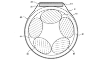
- FIG. 2 is a diagram showing an example (part 1) of the installation position of the magnetic sensor according to the embodiment of the present invention.
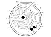
- FIG. 3 is a diagram showing an example (part 2) of the installation position of the magnetic sensor according to the embodiment of the present invention.
- FIG. 4 is a diagram showing the configuration of the management apparatus according to the embodiment of the present invention.
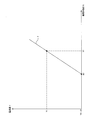
- FIG. 5 is a diagram showing a correspondence relationship between the current value of the direct current flowing through the power cable and the strength of the magnetic field generated in the power cable in the management system according to the embodiment of the present invention.
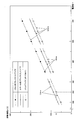
- FIG. 6 is a diagram illustrating a graph indicating speed information stored in the storage unit in the management device according to the embodiment of the present invention.
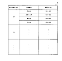
- FIG. 7 is a diagram showing a correspondence table stored in the storage unit in the management apparatus according to the embodiment of the present invention.
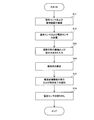
- FIG. 8 is a diagram showing an example of a flowchart defining an operation procedure at the time of initial setting of the management system according to the embodiment of the present invention.
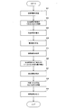
- FIG. 9 is a diagram showing an example of a flowchart defining an operation procedure during operation of the management system according to the embodiment of the present invention.
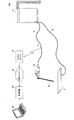
- FIG. 10 is a diagram showing a configuration of a management system according to a modification of the embodiment of the present invention.
- the format of the welding data transmitted from the recording device built in the welding apparatus may differ depending on the type of welding apparatus, that is, the manufacturer or model of the welding apparatus.
- a welding apparatus that does not include a recording device, such as an old welding apparatus may be provided. In such a case, it is difficult to manage the welding work, and it is even more difficult to manage the entire factory including a plurality of welding apparatuses in one system.
- the present disclosure has been made in order to solve the above-described problems.
- the purpose of the present disclosure is to provide a management system, a management device, and a sensor capable of performing management related to welding work regardless of the type and number of welding devices installed. It is to provide an installation method, a management method and a management program.
- the management system which concerns on embodiment of this invention is provided with the magnetic sensor provided corresponding to the welding apparatus, and the management apparatus which performs the process regarding welding operation,
- the said magnetic sensor is connected to the said welding apparatus.
- the magnetic field generated by the current flowing through the cable to be measured is measured, the measurement information indicating the measurement result is transmitted to the management device, the management device receives the measurement information transmitted from the magnetic sensor, the received
- the said process is performed based on measurement information
- the said magnetic sensor can be installed locally in the circumferential direction of the said cable.
- the configuration in which the magnetic sensor can be locally installed in the circumferential direction of the cable enables the magnetic sensor to be installed later on the cable regardless of the size and type of the cable diameter. That is, regardless of the type and number of welding apparatuses to which the cable is connected, the magnetic sensor can be installed in association with the welding apparatus. Therefore, it is possible to manage the welding work regardless of the type and number of welding apparatuses installed.
- management related to the welding work for each welding apparatus can be performed based on measurement information transmitted from each of the plurality of magnetic sensors.
- the magnetic sensor is installed on the cable connecting the power supply device and the welding device.
- the configuration in which the magnetic sensor is installed in the power cable for supplying electric power to the welding apparatus accurately measures the magnetic field generated by the current supplied to the welding apparatus, and performs management related to the welding operation more accurately. be able to.
- the management device determines whether or not a current is flowing through the cable as the processing based on the measurement information.
- the management device calculates an operation time of the welding operation as the processing based on the measurement information.
- the management device calculates a current value of the current as the processing based on the measurement information.
- the management device further calculates a welding amount of the welding material as the processing based on the current value.
- the production cost of the product can be calculated and the quality of the product can be evaluated based on the welding amount of the welding material.
- the management device calculates the welding amount based on the type of the linear welding material, the diameter of the welding material, and the current value.
- the amount of welding can be calculated more accurately in consideration of the type of welding material and the size of the diameter.
- the management device specifies a welding speed of the welding material based on the type, the size of the diameter, and the current value, and the welding amount based on the specified welding speed. Is calculated.
- the welding amount of the welding material can be calculated more accurately by an appropriate method.
- the management device specifies the welding posture of the worker as the processing based on the current value.
- the difficulty level of the welding operation can be grasped based on the welding posture, and the production cost of the product and the evaluation of the quality of the product can be performed according to the difficulty level of the welding operation.
- the management device is acquired by an acquisition unit that acquires measurement information indicating a measurement result of a magnetic field generated by a current flowing in a cable connected to a welding device, and the acquisition unit.
- a processing unit that calculates a current value of the current based on the measurement information and calculates a welding amount of the welding material based on the calculated current value.
- management related to the welding work for each welding apparatus can be performed based on measurement information transmitted from each of the plurality of magnetic sensors.
- the configuration for calculating the welding amount of the welding material for example, the production cost of the product and the evaluation of the quality of the product can be performed based on the welding amount of the welding material.
- the acquisition unit acquires the measurement information indicating the measurement result by the magnetic sensor installed in the cable connecting the power supply device and the welding device.
- the configuration in which the magnetic sensor is installed in the power cable for supplying electric power to the welding apparatus accurately measures the magnetic field generated by the current supplied to the welding apparatus, and performs management related to the welding operation more accurately. be able to.
- a sensor installation method includes a magnetic sensor provided corresponding to a welding device, and a management device that performs processing related to a welding operation based on a measurement result of the magnetic sensor.
- a sensor installation method in a management system comprising: preparing the magnetic sensor and the management device; and installing the magnetic sensor on a cable connecting a power supply device and the welding device.
- This method allows the magnetic sensor to be installed later on the cable regardless of the size and type of cable diameter. That is, regardless of the type and number of welding apparatuses to which the cable is connected, the magnetic sensor can be installed in association with the welding apparatus. Therefore, it is possible to manage the welding work regardless of the type and number of welding apparatuses installed.
- management related to the welding work for each welding apparatus can be performed based on measurement information transmitted from each of the plurality of magnetic sensors.
- the configuration in which the magnetic sensor is installed in the power cable for supplying power to the welding apparatus makes it possible to accurately measure the magnetic field generated by the current supplied to the welding apparatus and more accurately manage the welding operation. it can.
- a management method is a management method in a management apparatus that performs processing related to a welding operation, and shows a measurement result of a magnetic field generated by a current flowing in a cable connected to the welding apparatus.
- the method includes a step of acquiring information, a step of calculating a current value of the acquired current, and a step of calculating a welding amount of the welding material based on the calculated current value.
- management related to the welding work for each welding apparatus can be performed based on measurement information transmitted from each of the plurality of magnetic sensors.
- the configuration for calculating the welding amount of the welding material for example, the production cost of the product and the evaluation of the quality of the product can be performed based on the welding amount of the welding material.
- a management program is a management program used in a management apparatus, and measurement information indicating a measurement result of a magnetic field generated by a current flowing through a cable connected to a welding apparatus. And a processing unit that calculates a current value of the current based on the measurement information acquired by the acquiring unit, and calculates a welding amount of the welding material based on the calculated current value, It is a program to make it function as.
- management related to the welding work for each welding apparatus can be performed based on measurement information transmitted from each of the plurality of magnetic sensors.
- the configuration for calculating the welding amount of the welding material for example, the production cost of the product based on the welding amount and the quality evaluation can be performed.
- FIG. 1 is a diagram showing a configuration of a management system according to an embodiment of the present invention.
- the management system 301 includes one or more welding apparatuses 101, one or more magnetic sensors 111, one or more welding torches 121, one or more gas cylinders 122, and a power supply apparatus 131.
- the magnetic sensor 111 is provided corresponding to the welding apparatus 101. Further, the welding torch 121 is provided corresponding to the welding apparatus 101. Further, the gas cylinder 122 is provided corresponding to the welding apparatus 101. Note that the gas cylinders 122 may be provided corresponding to the plurality of welding apparatuses 101.
- the welding apparatus 101 is a semi-automatic welding machine, for example, and is assigned for each worker.
- the worker installs the welding apparatus 101 in the vicinity of the work place before the start of the welding operation, and connects one end of the power cable 51, one end of the control cable 52, and one end of the gas cable 53 to a plurality of unillustrated welding apparatuses 101. Connect to each terminal. Further, the operator connects the welding cable 54 extending from the welding torch 121 to a corresponding portion of the welding apparatus 101.
- the operator connects the other end of the power cable 51 and the other end of the control cable 52 to a plurality of terminals (not shown) of the power supply device 131, and connects the other end of the gas cable 53 to the gas cylinder 122. Further, the operator connects one end of the grounding cable 55 to the base material A that is an object to be welded, and connects the other end of the grounding cable 55 to a terminal (not shown) of the power supply device 131.
- the power supply device 131 detects the operation via the welding device 101 and the control cable 52. And if the power supply device 131 detects the said operation, for example, the alternating current received from the electric power system side will be converted into a direct current, and a direct current will be supplied to the welding apparatus 101 via the power cable 51.
- the welding apparatus 101 operates by receiving a direct current supplied from the power supply device 131 via the power cable 51, and supplies the linear welding material M to the welding torch 121 via the welding cable 54.
- the welding material M is, for example, a welding wire, and is provided in the welding apparatus 101 by being wound in a coil shape.
- the welding material M supplied to the welding torch 121 is supplied with a direct current through the power supply device 131, the power supply cable 51, the welding device 101, the welding cable 54, and the welding torch 121 to become an electrode.
- the welding material M and the base material A are melted and integrated by the heat generated by the arc generated between the welding material M and the base material A, which are electrodes.
- the welding apparatus 101 further releases the shield gas supplied from the gas cylinder 122 via the gas cable 53 from the welding torch 121 via the welding cable 54.
- the shield gas is, for example, carbon dioxide.
- the magnetic sensor 111 is, for example, a battery-driven sensor, and measures a magnetic field generated by a direct current flowing through the power cable 51 regularly or irregularly. Then, the magnetic sensor 111 transmits magnetic field information (measurement information) indicating the measurement result to the access point 151.
- the magnetic field information transmitted from the magnetic sensor 111 includes at least a magnetic field strength generated in the power cable 51, a voltage calculated based on the magnetic field strength, and a current value calculated based on the magnetic field strength. Either one is shown.
- the magnetic field information indicates the strength of the magnetic field.
- the access point 151 receives the magnetic field information from the magnetic sensor 111 and transmits the received magnetic field information to the management apparatus 201 via the internal network 401.
- the management apparatus 201 receives the magnetic field information transmitted from the access point 151 via the internal network 401, and performs processing related to the welding work based on the received magnetic field information.
- the management device 201 calculates the working time, calculates the welding amount of the welding material M, calculates the amount of shield gas used, and specifies the welding posture of the worker during the welding operation as processing related to the welding operation. Do at least one of the following:
- the management device 201 outputs, for example, at least one of a processing result, that is, a calculated work time, a welding amount, a usage amount of a shield gas, and a specified welding posture. Specifically, the management apparatus 201 displays characters indicating the processing result on the monitor of the terminal apparatus 202.
- the management apparatus 201 When the management system 301 includes a plurality of welding apparatuses 101, a plurality of magnetic sensors 111, a plurality of welding torches 121, and a plurality of gas cylinders 122, the management apparatus 201 has a plurality of transmissions transmitted from the plurality of magnetic sensors 111, respectively. Based on the magnetic field information, for example, processing related to the welding operation for each welding apparatus 101 is performed. Then, the administrator or the like can manage the welding operation in the entire factory where the plurality of welding apparatuses 101 are provided by confirming the processing result displayed on the monitor of the terminal device 202, for example.
- the current supplied from the power supply device 131 to the welding device 101 via the power cable 51 may be an alternating current.
- the magnetic sensor 111 measures the magnetic field generated by the alternating current flowing through the power cable 51.
- FIG. 2 is a diagram showing an example (part 1) of the installation position of the magnetic sensor according to the embodiment of the present invention. In FIG. 2, the cross section of the power cable 51 and the magnetic sensor 111 are shown.
- a plurality of conductive wires 61 are accommodated inside power supply cable 51 in a twisted state.
- a direct current flows in the power cable 51, a magnetic field is generated in the circumferential direction of each conductive wire 61.
- a clamp meter may be used as a sensor for measuring the magnetic field generated in the power cable 51.
- the power cable 51 is sandwiched between iron cores in the clamp meter.
- a magnetic field is generated in the circumferential direction of the iron core due to the direct current flowing through the power cable 51, for example, a voltage is output by the magnetic flux passing through the hall element provided in the iron core.
- the magnetic field generated in the cable 51 can be measured.
- the magnetic sensor 111 that is locally installed in the circumferential direction of the power cable 51 is used instead of using the clamp meter.
- the magnetic sensor 111 directly measures a part of the magnetic field generated around the power cable 51, unlike a clamp meter that converts the magnetic field generated around the power cable 51 into a voltage by converging it on the iron core.
- the measurement accuracy of the magnetic field by the magnetic sensor 111 may be lower than the measurement of the magnetic field by the clamp meter.
- the measurement accuracy is not as high as that of the clamp meter, it is possible to determine whether or not current is flowing through the power cable 51 based on the measurement result by the magnetic sensor 111. For this reason, it is possible to perform management related to the welding work, such as grasping the operating status of the welding apparatus 101 using the magnetic sensor 111.
- the magnetic sensor 111 is, for example, an IC (Integrated Circuit) chip including a sensor unit 21 that measures a magnetic field and a processing circuit 22 that performs wireless communication.
- the magnetic sensor 111 is fixed to the power cable 51 using a band 65 or the like.
- the sensor unit 21 covers a part of the outer periphery of the power cable 51, for example, a portion of 50% or less of the outer periphery. More preferably, the sensor unit 21 covers a portion of 30% or less of the outer periphery of the power cable 51.
- the sensor unit 21 measures, for example, a magnetic field generated in the conductive line 61 closest to itself among the plurality of conductive lines 61 as a magnetic field generated in the power cable 51.
- the processing circuit 22 transmits a wireless signal including magnetic field information indicating a measurement result by the sensor unit 21 to the management apparatus 201.
- the magnetic sensor 111 can be installed regardless of the size and type of the diameter of the power cable 51, for example, a plurality of welding devices 101 are provided, and each welding device 101 is provided. Even if the diameters of the power cables 51 connected to each other are different from each other, the same magnetic sensor 111 can be installed for each power cable 51.
- FIG. 3 is a diagram showing an example (part 2) of the installation position of the magnetic sensor according to the embodiment of the present invention. In FIG. 3, the cross section of the welding cable 54 and the magnetic sensor 111 are shown.
- a power cable 51 including a plurality of conductive wires 61 and a welding material M, a control cable 52, and a gas cable 53 are accommodated in the welding cable 54.
- the magnetic sensor 111 may be installed on the welding cable 54 instead of being installed on the power cable 51. That is, the magnetic sensor 111 may be locally installed in the circumferential direction of the welding cable 54.
- the distance between the magnetic sensor 111 and the power cable 51 differs depending on the installation position of the magnetic sensor 111 with respect to the welding cable 54. That is, when the magnetic sensor 111 is installed at a position relatively far from the power cable 51 accommodated in the welding cable 54, the magnetic sensor 111 may not be able to accurately measure the magnetic field generated in the power cable 51. is there. For this reason, as shown in FIG. 2, the magnetic sensor 111 is preferably installed directly on the power cable 51.
- FIG. 4 is a diagram showing the configuration of the management apparatus according to the embodiment of the present invention.
- management device 201 includes acquisition unit 11, processing unit 12, storage unit 13, and output unit 14.
- the acquisition unit 11 receives the magnetic field information transmitted from the magnetic sensor 111 via the access point 151 and the internal network 401, and outputs the received magnetic field information to the processing unit 12.
- the processing unit 12 stores, for example, the magnetic field information received from the acquisition unit 11 in the storage unit 13 in association with date / time information indicating the current date / time. And the process part 12 performs the process regarding welding work based on the magnetic field information preserve
- the output unit 14 outputs the contents of the result information received from the processing unit 12 in a recognizable manner. Specifically, the output unit 14 displays characters or the like indicating the content of the result information on the monitor of the terminal device 202, for example. Hereinafter, details of processing by the processing unit 12 will be described.
- the processing unit 12 reads, for example, magnetic field information stored in the storage unit 13 as a process related to welding work, and based on the read magnetic field information, the welding apparatus The operation status of the welding operation is judged, and the working time of the welding work is calculated.
- the processing unit 12 determines that a current is flowing through the power cable 51 and the welding apparatus 101. Is determined to be in operation.
- the processing unit 12 determines that no current flows through the power cable 51, and the welding apparatus 101 is not operating. Judge that there is.
- the processing unit 12 refers to the date and time information associated with the magnetic field information, for example, and makes the above determination for each of the plurality of magnetic field information stored in the storage unit 13 in a predetermined period such as one week. Do. Thereby, the process part 12 calculates the operation time of the welding apparatus 101 in the said predetermined period as a work time of welding work.
- the processing unit 12 calculates the current value Y of the direct current flowing through the power cable 51 based on the magnetic field information read from the storage unit 13 as a process related to the welding work, for example.
- the storage unit 13 stores current magnetic field information indicating a relational expression f between the current value Y of the direct current flowing through the power cable 51 and the magnetic field strength X generated in the power cable 51.
- the relational expression f is calculated by the processing unit 12 at the time of initial setting before the start of the welding work, for example.
- FIG. 5 is a diagram showing a correspondence relationship between the value of the direct current flowing through the power cable and the strength of the magnetic field generated in the power cable in the management system according to the embodiment of the present invention.
- the vertical axis of the graph shown in FIG. 5 indicates the current value Y, and the horizontal axis indicates the magnetic field strength X.
- the administrator attaches a current sensor to the power cable 51 at the time of initial setting.
- the current sensor is, for example, a handy type DC current sensor, measures the current value Y, and transmits current information indicating the measurement result to the management apparatus 201. Then, the acquisition unit 11 in the management device 201 receives the current information transmitted from the current sensor, and outputs the received current information to the processing unit 12.
- the processing unit 12 calculates the relational expression f based on the current value Y indicated by the current information from the current sensor and the magnetic field strength X indicated by the magnetic field information from the magnetic sensor 111.
- the processing unit 12 when receiving current information from the acquisition unit 11, the processing unit 12 reads the latest magnetic field information stored in the storage unit 13, reads the current value Y indicated by the current information, and the read magnetic field information. The magnetic field strength X shown is correlated. Then, the processing unit 12 calculates the relational expression f using a plurality of sets of the current value Y and the magnetic field strength X that are associated in this way.
- the relational expression f is calculated.
- the processing unit 12 is not limited to the above calculation method, and may calculate the relational expression f by linear regression analysis using a plurality of sets of the current value Y and the magnetic field strength X, for example. .
- the processing unit 12 calculates the relational expression f
- the processing unit 12 stores the current magnetic field information indicating the calculated relational expression f in the storage unit 13.
- the process part 12 outputs the completion information which shows that the preservation
- the output unit 14 receives the completion information from the processing unit 12, the output unit 14 displays, for example, on the monitor of the terminal device 202 that the storage of the current magnetic field information is completed. Then, when the administrator grasps that the storage of the current magnetic field information is completed by checking the display on the monitor, the administrator removes the current sensor from the power cable 51.
- the processing unit 12 receives magnetic field information from the magnetic sensor 111 via the access point 151, the internal network 401, and the acquisition unit 11, the relational expression f indicated by the current magnetic field information stored in the storage unit 13. And the current value Y is calculated based on the magnetic field strength X indicated by the magnetic field information.
- the processing unit 12 may be configured to calculate a relational expression f indicating a correspondence relationship between the temperature, the current value Y, and the magnetic field strength X at the time of initial setting.
- a temperature sensor is provided around the welding apparatus 101.
- the temperature sensor measures the environmental temperature of the welding apparatus 101 and transmits temperature information as a measurement result to the management apparatus 201 via the access point 151 and the internal network 401.
- the processing unit 12 uses the temperature indicated by the temperature information, for example, For each range, a relational expression f indicating the correspondence between the current value Y and the magnetic field strength X is calculated.
- the processing unit 12 is configured such that when the environmental temperature of the welding apparatus 101 is 10 ° C. or less, when the environmental temperature is 10 ° C. to 20 ° C., when the environmental temperature is 20 ° C. to 30 ° C., and A plurality of relational expressions f indicating the correspondence between the current value Y and the magnetic field strength X in each case where the temperature is 30 ° C. or higher are calculated. Then, the processing unit 12 stores the current magnetic field information indicating the calculated plurality of relational expressions f in the storage unit 13.
- the processing unit 12 when the processing unit 12 receives the temperature information from the temperature sensor, the processing unit 12 corresponds to the temperature indicated by the temperature information from among a plurality of relational expressions f indicated by the current magnetic field information stored in the storage unit 13.
- the relational expression f is specified.
- the processing unit 12 calculates the current value Y based on the magnetic field strength X indicated by the magnetic field information and the specified relational expression f.
- the storage unit 13 stores speed information indicating a correspondence relationship between the current value Y of the direct current flowing through the power cable 51 and the welding speed of the welding material M. Then, the processing unit 12 calculates the welding amount based on the speed information stored in the storage unit 13 and the work time calculated by the method described in “(a) Calculation of work time”.
- the speed information indicates a graph indicating a correspondence relationship between the type of the welding material M, the diameter of the welding material M, the current value Y, and the welding speed of the welding material M.
- FIG. 6 is a diagram showing a graph indicating the speed information stored in the storage unit in the management apparatus according to the embodiment of the present invention.
- the vertical axis of the graph shown in FIG. 6 indicates the welding rate [g / min], and the horizontal axis indicates the current value Y [A].
- the terminal device 202 when the administrator inputs the type and diameter of the welding material M to the terminal device 202 at the time of initial setting, the terminal device 202 notifies the management device 201 of the input content. Then, an information acquisition unit (not shown) in the management device 201 outputs material information indicating the type and diameter of the welding material M notified from the terminal device 202 to the processing unit 12.
- the processing unit 12 receives the material information received from the information acquisition unit, the current value Y calculated by the method described in “(b) Calculation of current value”, and the speed information stored in the storage unit 13, that is, FIG.
- the welding speed of the welding material M is specified based on the graph shown in FIG.
- Part 12 specifies 75 g / min as the welding rate.
- the process part 12 may calculate the usage-amount of shielding gas further based on the calculated welding amount as a process regarding welding work. For example, the processing unit 12 calculates (constant K) ⁇ (welding amount of the welding material M) as the usage amount of the shielding gas.
- the process part 12 specifies the welding posture of the operator in welding work further based on the calculated electric current value Y as a process regarding welding work.
- the storage unit 13 includes a correspondence table showing correspondence between three parameters, that is, correspondence between the diameter of the welding material M and the current value Y of the direct current flowing through the power cable 51 and the welding posture. T is stored.
- FIG. 7 is a diagram showing a correspondence table stored in the storage unit in the management apparatus according to the embodiment of the present invention.
- the processing unit 12 specifies the welding posture of the worker based on, for example, the material information received from the information acquisition unit described above, the calculated current value Y, and the correspondence table T stored in the storage unit 13.
- the processing unit 12 specifies “standing” as the welding posture.
- the processing unit 12 further uses at least one of the calculated work time, the welding amount of the welding material M, the amount of use of the shielding gas, and the specified welding posture as the processing related to the welding work. Further, it may be configured to calculate the production cost of the product and evaluate the quality of the product.
- the processing unit 12 outputs product information indicating the calculated production cost and quality evaluation result to the output unit 14, and the output unit 14 can recognize the content indicated by the product information received from the processing unit 12. Output to.
- FIG. 8 is a diagram showing an example of a flowchart defining an operation procedure at the time of initial setting of the management system according to the embodiment of the present invention.
- Each device in the management system 301 includes a computer, and an arithmetic processing unit such as a CPU in the computer reads and executes a program including a part or all of each step of the following sequence from a memory (not shown).
- an arithmetic processing unit such as a CPU in the computer reads and executes a program including a part or all of each step of the following sequence from a memory (not shown).
- Each of the programs of the plurality of apparatuses can be installed from the outside.
- the programs of the plurality of devices and the plurality of sensors are distributed while being stored in the recording medium.
- the administrator prepares magnetic sensor 111 and management device 201 (step S11).
- the administrator installs the magnetic sensor 111 and the current sensor on the power cable 51 (step S12).
- the administrator inputs the type and diameter of the welding material M to the terminal device 202, and the terminal device 202 notifies the input content to the management device 201 (step S13).
- the management apparatus 201 determines the current value Y of the direct current flowing through the power cable 51 based on the magnetic field strength X indicated by the magnetic field information from the magnetic sensor 111 and the current value Y indicated by the current information from the current sensor. And a relational expression f between the magnetic field strength X generated in the power cable 51 is calculated (step S14).
- the management device 201 stores the current magnetic field information indicating the calculated relational expression f, and notifies the fact that the storage of the current magnetic field information is completed by displaying it on the monitor of the terminal device 202 or the like (step S15). .
- the administrator grasps that the storage of the current magnetic field information is completed by confirming the display on the monitor or the like, the administrator removes the current sensor from the power cable 51 (step S16). Note that the administrator may input the type and diameter of the welding material M (step S13) after removing the current sensor.
- FIG. 9 is a diagram showing an example of a flowchart defining an operation procedure during operation of the management system according to the embodiment of the present invention.
- management device 201 receives magnetic field information transmitted from magnetic sensor 111 (step S21). And the management apparatus 201 judges whether the electric current is flowing into the power cable 51 based on the received magnetic field information, and judges whether the welding apparatus 101 is operating based on the judgment result. (Step S22).
- the management device 201 calculates the working time of the welding work based on the determination result of whether or not the welding device 101 is in operation (step S23).
- the management device 201 calculates the current value Y of the direct current flowing through the power cable 51 based on the magnetic field information transmitted from the magnetic sensor 111 and the current magnetic field information stored at the time of initial setting (step S24). .
- the management device 201 specifies the welding speed of the welding material M based on the type and diameter of the welding material M notified from the terminal device 202 and the calculated current value Y at the time of initial setting ( Step S25).
- the management device 201 calculates the welding amount of the welding material M and the usage amount of the shielding gas based on the specified welding speed and the calculated work time (step S26).
- the management device 201 identifies the welding posture of the operator based on the diameter of the welding material M, the current value Y, and the posture information stored in advance (step S27).
- the management apparatus 201 calculates the production cost of the product and evaluates the quality based on the calculated work time, the welding amount of the welding material M and the usage amount of the shield gas, and the specified welding posture (step S28). ).
- the management device 201 outputs, for example, the operation time, the welding amount of the welding material M, the usage amount of the shield gas, the welding posture, the production cost, and the quality evaluation result as recognizable results (step S29). .
- the management apparatus 201 determines whether or not the welding apparatus 101 is in operation (step S22), calculates a working time (step S23), calculates a current value Y (step S24), and specifies a welding speed (step). S25), calculation of the welding amount of the welding material M and the usage amount of the shielding gas (step S26), specification of the welding posture (step S27), calculation of production cost and evaluation of quality (step S28) are performed.
- the configuration is not limited to the configuration, and may be a configuration that performs a part of the above-described processing, for example.
- FIG. 10 is a diagram showing a configuration of a management system according to a modification of the embodiment of the present invention.
- the management system 301 may include one or more welding apparatuses 101 instead of one or more welding apparatuses 101, one or more welding torches 121, and one or more gas cylinders 132. Good.
- the welding apparatus 102 is, for example, a covered arc welder, and is assigned to each worker. The worker installs the welding apparatus 102 near the work place before the start of the welding work, and connects one end of the power cable 51 to a terminal (not shown) of the welding apparatus 102.
- the worker connects the other end of the power cable 51 to a terminal (not shown) of the power supply device 131. Further, the operator connects one end of the grounding cable 55 to the base material A that is an object to be welded, and connects the other end of the grounding cable 55 to a terminal (not shown) of the power supply device 131.
- the welding apparatus 102 operates by receiving a direct current supplied from the power supply apparatus 131 via the power supply cable 51.
- the welding rod Ma attached to the tip of the welding apparatus 102 serves as an electrode, and the welding rod Ma and the base material A are melted and integrated by heat generated by the arc generated between the welding rod Ma and the base material A. To do.
- the magnetic sensor 111 is installed in the power cable 51, measures the magnetic field generated in the power cable 51, and uses the magnetic field information indicating the measurement result as the access point 151 and the internal network.
- the data is transmitted to the management apparatus 201 via 401.
- the management apparatus 201 receives the magnetic field information from the magnetic sensor 111 similarly to the management apparatus 201 shown in FIG. 1, and performs the process regarding welding work based on the received magnetic field information.
- Patent Document 1 describes a system including a recording device that is built in a welding apparatus and records welding data related to a welding operation, and a management device that collects the welding data and processes the collected welding data. Has been.
- the format of the welding data transmitted from the recording device built in the welding apparatus may differ depending on the type of the welding apparatus, that is, the manufacturer or model of the welding apparatus.
- a welding apparatus that does not include a recording device, such as an old welding apparatus may be provided. In such a case, it is difficult to manage the welding work, and it is even more difficult to manage the entire factory including a plurality of welding apparatuses in one system.
- the magnetic sensor 111 is provided corresponding to the welding apparatus 101.
- the management apparatus 201 performs processing related to the welding work.
- the magnetic sensor 111 measures a magnetic field generated by a current flowing through the power cable 51 connected to the welding apparatus 101 and transmits measurement information indicating the measurement result to the management apparatus 201.
- the management apparatus 201 receives the measurement information transmitted from the magnetic sensor 111 and performs processing based on the received measurement information.
- the magnetic sensor 111 can be locally installed in the circumferential direction of the power cable 51.
- the configuration in which the magnetic sensor 111 can be locally installed in the circumferential direction of the power cable 51 allows the magnetic sensor 111 to be retrofitted to the power cable 51 regardless of the size and type of the power cable 51. Can be installed at. That is, regardless of the type and number of welding apparatuses 101 to which the power cable 51 is connected, the magnetic sensor 111 can be installed in association with the welding apparatus 101. Therefore, regardless of the type and number of the installed welding apparatuses 101, it is possible to manage the welding operation.
- the magnetic sensor 111 is installed in the power cable 51 that connects the power device 131 and the welding device 101.
- the magnetic sensor 111 is installed in the power cable 51 for supplying electric power to the welding apparatus 101, thereby accurately measuring the magnetic field generated by the direct current supplied to the welding apparatus 101 and managing the welding operation. Can be performed more accurately.
- the management device 201 determines whether or not a current is flowing through the power cable 51 as the above processing based on the measurement information from the magnetic sensor 111.
- the management device 201 calculates the work time of the welding work as the above process based on the measurement information from the magnetic sensor 111.
- the management device 201 calculates the current value Y of the direct current flowing through the power cable 51 as the above processing based on the measurement information from the magnetic sensor 111.
- the management apparatus 201 further calculates the welding amount of the welding material M as the above processing based on the calculated current value Y.
- the management device 201 uses the welding material M based on the type of the linear welding material M, the diameter of the welding material M, and the calculated current value Y.
- the welding amount of M is calculated.
- the amount of welding can be calculated more accurately in consideration of the type and diameter of the welding material M.
- the management apparatus 201 welds the welding material M based on the type of the welding material M, the diameter of the welding material M, and the calculated current value Y.
- the speed is specified, and the welding amount of the welding material M is calculated based on the specified welding speed.
- the welding amount of the welding material M can be calculated more accurately by an appropriate method.
- the management device 201 specifies the welding posture of the worker as the above processing based on the calculated current value Y.
- the difficulty level of the welding operation can be grasped based on the welding posture, and the production cost of the product and the evaluation of the quality of the product can be performed according to the difficulty level of the welding operation.
- the acquisition unit 11 acquires measurement information indicating the measurement result of the magnetic field generated by the direct current flowing through the power cable 51 connected to the welding apparatus 101. Further, the processing unit 12 calculates the current value Y of the direct current based on the measurement information acquired by the acquisition unit 11, and calculates the welding amount of the welding material M based on the calculated current value Y.
- the product production cost can be calculated and the product quality can be evaluated based on the welding amount of the welding material M.
- the acquisition unit 11 acquires measurement information indicating a measurement result by the magnetic sensor 111 installed in the power cable 51 that connects the power device 131 and the welding device 101. To do.
- the magnetic sensor 111 is installed in the power cable 51 for supplying electric power to the welding apparatus 101, thereby accurately measuring the magnetic field generated by the direct current supplied to the welding apparatus 101 and managing the welding operation. Can be performed more accurately.
- the sensor installation method in the management system 301 includes the steps of preparing the magnetic sensor 111 and the management device 201, and the magnetic sensor 111 to the power cable 51 connecting the power supply device 131 and the welding device 101. And installing a step.
- the magnetic sensor 111 can be retrofitted with respect to the power cable 51 regardless of the size and type of the diameter of the power cable 51. That is, regardless of the type and number of welding apparatuses 101 to which the power cable 51 is connected, the magnetic sensor 111 can be installed in association with the welding apparatus 101. Therefore, regardless of the type and number of the installed welding apparatuses 101, it is possible to manage the welding operation.
- the configuration in which the magnetic sensor 111 is installed in the power cable 51 for supplying power to the welding apparatus 101 accurately measures the magnetic field generated by the direct current supplied to the welding apparatus 101, thereby further managing the welding operation. Can be done accurately.
- the management apparatus 201 is not limited to a configuration that performs processing related to the welding operation, and is, for example, another type of apparatus other than the welding apparatus 101 and driven by a current supplied through a cable. It is possible to perform processing relating to the device to be performed.
- the management device 201 acquires measurement information indicating the measurement result of the magnetic field generated by the current flowing through the cable, and determines whether or not current is flowing through the cable based on the acquired measurement information. Based on the determination result, the management device 201 can manage, for example, the operating status of the device driven by the current supplied through the cable. Moreover, the management apparatus 201 can also predict the failure time of the apparatus based on the operating status of the apparatus, for example.
- part or all of the functions of the management apparatus 201 according to the embodiment of the present invention may be provided by cloud computing. That is, at least one of the management apparatuses 201 may be configured by a plurality of cloud servers or the like.
- a magnetic sensor provided corresponding to the welding device; A management device for processing related to welding work, The magnetic sensor measures a magnetic field generated by a current flowing in a cable connected to the welding apparatus, and transmits measurement information indicating a measurement result to the management apparatus.
- the management device receives the measurement information transmitted from the magnetic sensor, performs the processing based on the received measurement information,
- the magnetic sensor can be locally installed in the circumferential direction of the cable,
- the welding apparatus is a semi-automatic welding machine or a coated arc welding machine,
- the cable is a power cable for supplying a direct current to the welding apparatus,
- a plurality of the welding apparatus and the magnetic sensor are provided,
- the management device performs processing related to the welding work for each welding device based on the plurality of measurement information respectively transmitted from the plurality of magnetic sensors, and outputs the processing result in a recognizable manner,
- the management system in which the plurality of cables connected to the plurality of welding apparatuses have different diameters.
- An acquisition unit for acquiring measurement information indicating a measurement result of a magnetic field generated by a current flowing in a cable connected to the welding apparatus; Based on the measurement information acquired by the acquisition unit, to calculate the current value of the current, based on the calculated current value, a processing unit to calculate the welding amount of the welding material, An output unit for recognizing and outputting a processing result by the processing unit,
- the welding apparatus is a semi-automatic welding machine or a coated arc welding machine,
- the cable is a power cable for supplying a direct current to the welding apparatus,
- a plurality of the welding devices are provided,
- the acquisition unit acquires a plurality of measurement information respectively corresponding to the plurality of welding apparatuses,
- the processing unit performs processing related to a welding operation for each welding apparatus based on the plurality of pieces of measurement information acquired by the acquisition unit,
Landscapes
- Engineering & Computer Science (AREA)
- Physics & Mathematics (AREA)
- General Physics & Mathematics (AREA)
- Mechanical Engineering (AREA)
- General Engineering & Computer Science (AREA)
- Manufacturing & Machinery (AREA)
- Quality & Reliability (AREA)
- Automation & Control Theory (AREA)
- Plasma & Fusion (AREA)
- Measurement Of Current Or Voltage (AREA)
- Arc Welding Control (AREA)
- General Factory Administration (AREA)
Abstract
管理システム(301)は、溶接装置(101)に対応して設けられた磁気センサ(111)と、溶接作業に関する処理を行う管理装置(201)とを備え、前記磁気センサ(111)は、前記溶接装置(101)に接続されるケーブル(51)に流れる電流、により生じる磁場を計測し、計測結果を示す計測情報を前記管理装置(201)へ送信し、前記管理装置(201)は、前記磁気センサ(111)から送信された前記計測情報を受信し、受信した前記計測情報に基づいて前記処理を行い、前記磁気センサ(111)は、前記ケーブル(51)の周方向において局所的に設置可能である。
Description
本発明は、管理システム、管理装置、センサ設置方法、管理方法および管理プログラムに関する。
この出願は、2017年1月20日に出願された日本出願特願2017-008827号を基礎とする優先権を主張し、その開示のすべてをここに取り込む。
この出願は、2017年1月20日に出願された日本出願特願2017-008827号を基礎とする優先権を主張し、その開示のすべてをここに取り込む。
特許文献1(特開2016-038709号公報)には以下のような技術が記載されている。
すなわち、溶接システムは、溶接ワイヤを溶接トーチに供給して溶接を行う溶接装置と、該溶接装置に内蔵されており、溶接装置の溶接操作に関する溶接データを記録する溶接データ記録装置と、前記溶接装置の溶接データ記録装置で記録された溶接データを収集し処理する溶接データ管理装置とを備え、前記溶接データ記録装置は、前記溶接トーチに供給された前記溶接ワイヤの量を検出するワイヤ使用量検出器と、前記溶接装置の溶接電流を検出する電流検出器と、前記溶接データ記録装置で記録した前記溶接データを前記溶接データ管理装置に無線送信する無線送信機とを備え、前記溶接データ管理装置は、前記無線送信機から送信される前記溶接装置に関する前記溶接データを収集するデータ収集部と、収集された前記溶接データを処理するデータ処理部とを含む。
(1)本開示の管理システムは、溶接装置に対応して設けられた磁気センサと、溶接作業に関する処理を行う管理装置とを備え、前記磁気センサは、前記溶接装置に接続されるケーブルに流れる電流、により生じる磁場を計測し、計測結果を示す計測情報を前記管理装置へ送信し、前記管理装置は、前記磁気センサから送信された前記計測情報を受信し、受信した前記計測情報に基づいて前記処理を行い、前記磁気センサは、前記ケーブルの周方向において局所的に設置可能である。
(10)本開示の管理装置は、溶接装置に接続されるケーブルに流れる電流、により生じる磁場の計測結果を示す計測情報を取得する取得部と、前記取得部により取得された前記計測情報に基づいて、前記電流の電流値を算出し、算出した前記電流値に基づいて、溶接材料の溶着量を算出する処理部とを備える。
(12)本開示のセンサ設置方法は、溶接装置に対応して設けられた磁気センサと、前記磁気センサによる計測結果に基づいて、溶接作業に関する処理を行う管理装置とを備える管理システムにおける管理方法であって、前記磁気センサおよび前記管理装置を準備するステップと、電源装置と前記溶接装置とを接続するケーブルに前記磁気センサを設置するステップとを含む。
(13)本開示の管理方法は、溶接作業に関する処理を行う管理装置における管理方法であって、溶接装置に接続されるケーブルに流れる電流、により生じる磁場の計測結果を示す計測情報を取得するステップと、取得した前記電流の電流値を算出するステップと、算出した前記電流値に基づいて、溶接材料の溶着量を算出するステップとを含む。
(14)本開示の管理プログラムは、管理装置において用いられる管理プログラムであって、コンピュータを、溶接装置に接続されるケーブルに流れる電流、により生じる磁場の計測結果を示す計測情報を取得する取得部と、前記取得部により取得された前記計測情報に基づいて、前記電流の電流値を算出し、算出した前記電流値に基づいて、溶接材料の溶着量を算出する処理部、として機能させるためのプログラムである。
本開示の一態様は、このような特徴的な処理部を備える管理装置として実現され得るだけでなく、管理装置の一部又は全部を実現する半導体集積回路として実現され得る。
従来、溶接作業に関する管理を行うためのシステムが開発されている。
[本開示が解決しようとする課題]
溶接装置に内蔵された記録装置から送信される溶接データは、溶接装置の種類、すなわち溶接装置のメーカまたは機種ごとに形式が異なることがある。また、古い溶接装置など、記録装置が内蔵されていない溶接装置が設けられることがある。このような場合、溶接作業に関する管理を行うことが困難であり、特に、複数の溶接装置を備える工場全体を1つのシステムにおいて管理することはより一層困難である。
溶接装置に内蔵された記録装置から送信される溶接データは、溶接装置の種類、すなわち溶接装置のメーカまたは機種ごとに形式が異なることがある。また、古い溶接装置など、記録装置が内蔵されていない溶接装置が設けられることがある。このような場合、溶接作業に関する管理を行うことが困難であり、特に、複数の溶接装置を備える工場全体を1つのシステムにおいて管理することはより一層困難である。
本開示は、上述の課題を解決するためになされたもので、その目的は、設置された溶接装置の種類および個数に関わらず、溶接作業に関する管理を行うことのできる管理システム、管理装置、センサ設置方法、管理方法および管理プログラムを提供することである。
[本開示の効果]
本開示によれば、設置された溶接装置の種類および個数に関わらず、溶接作業に関する管理を行うことができる。
本開示によれば、設置された溶接装置の種類および個数に関わらず、溶接作業に関する管理を行うことができる。
[本願発明の実施形態の説明]
最初に、本発明の実施形態の内容を列記して説明する。
最初に、本発明の実施形態の内容を列記して説明する。
(1)本発明の実施の形態に係る管理システムは、溶接装置に対応して設けられた磁気センサと、溶接作業に関する処理を行う管理装置とを備え、前記磁気センサは、前記溶接装置に接続されるケーブルに流れる電流、により生じる磁場を計測し、計測結果を示す計測情報を前記管理装置へ送信し、前記管理装置は、前記磁気センサから送信された前記計測情報を受信し、受信した前記計測情報に基づいて前記処理を行い、前記磁気センサは、前記ケーブルの周方向において局所的に設置可能である。
このように、磁気センサがケーブルの周方向において局所的に設置可能である構成により、ケーブルの径の大きさおよび種類に関わらず、磁気センサをケーブルに対して後付けで設置することができる。すなわち、ケーブルの接続先である溶接装置の種類および個数に関わらず、溶接装置に磁気センサを対応づけて設置することができる。したがって、設置された溶接装置の種類および個数に関わらず、溶接作業に関する管理を行うことができる。
また、複数の溶接装置および複数の磁気センサが設けられている場合、複数の磁気センサからそれぞれ送信される計測情報に基づいて、溶接装置ごとの溶接作業に関する管理を行うことができる。
(2)好ましくは、前記磁気センサは、電源装置と前記溶接装置とを接続する前記ケーブルに設置される。
このように、溶接装置へ電力を供給するための電源ケーブルに磁気センサが設置される構成により、溶接装置へ供給される電流により生じる磁場を精度よく計測し、溶接作業に関する管理をより正確に行うことができる。
(3)好ましくは、前記管理装置は、前記計測情報に基づいて、前記処理として、前記ケーブルに電流が流れているか否かを判断する。
このような構成により、ケーブルに生じる磁場の計測結果に基づいて、当該ケーブルに接続される溶接装置の稼働状況を把握することできる。
(4)好ましくは、前記管理装置は、前記計測情報に基づいて、前記処理として、前記溶接作業の作業時間を算出する。
このような構成により、たとえば、作業時間に基づく、製品の生産コストの算出および製品の品質の評価を行うことができる。
(5)好ましくは、前記管理装置は、前記計測情報に基づいて、前記処理として、前記電流の電流値を算出する。
このような構成により、算出した電流値を用いて、溶接装置の動作を的確に管理し、溶接作業に関する管理をより適切に行うことができる。
(6)より好ましくは、前記管理装置は、前記電流値に基づいて、前記処理として、さらに、溶接材料の溶着量を算出する。
このような構成により、たとえば、溶接材料の溶着量に基づく、製品の生産コストの算出および製品の品質の評価を行うことができる。
(7)好ましくは、前記管理装置は、線状の前記溶接材料の種類、前記溶接材料の径の大きさ、および前記電流値に基づいて、前記溶着量を算出する。
このような構成により、溶接材料の種類および径の大きさを考慮して、溶着量をより正確に算出することができる。
(8)より好ましくは、前記管理装置は、前記種類、前記径の大きさ、および前記電流値に基づいて、前記溶接材料の溶着速度を特定し、特定した前記溶着速度に基づいて前記溶着量を算出する。
このような構成より、溶接材料の溶着量を、適切な方法でより一層正確に算出することができる。
(9)好ましくは、前記管理装置は、前記電流値に基づいて、前記処理として、作業者の溶接姿勢を特定する。
このような構成により、たとえば、溶接姿勢に基づいて溶着作業の難易度を把握し、溶接作業の難易度に応じた、製品の生産コストの算出および製品の品質の評価を行うことができる。
(10)本発明の実施の形態に係る管理装置は、溶接装置に接続されるケーブルに流れる電流、により生じる磁場の計測結果を示す計測情報を取得する取得部と、前記取得部により取得された前記計測情報に基づいて、前記電流の電流値を算出し、算出した前記電流値に基づいて、溶接材料の溶着量を算出する処理部とを備える。
このような構成により、ケーブルの径の大きさおよび種類に関わらず、たとえば磁気センサをケーブルに対して後付けで設置することにより、ケーブルに生じる磁場の計測結果を取得して、当該計測結果に基づく溶着量の算出を行うことができる。したがって、設置された溶接装置の種類および個数に関わらず、溶接作業に関する管理を行うことができる。
また、複数の溶接装置および複数の磁気センサが設けられている場合、複数の磁気センサからそれぞれ送信される計測情報に基づいて、溶接装置ごとの溶接作業に関する管理を行うことができる。
また、溶接材料の溶着量を算出する構成により、たとえば、溶接材料の溶着量に基づく、製品の生産コストの算出および製品の品質の評価を行うことができる。
(11)好ましくは、前記取得部は、電源装置と前記溶接装置とを接続する前記ケーブルに設置された磁気センサによる前記計測結果を示す前記計測情報を取得する。
このように、溶接装置へ電力を供給するための電源ケーブルに磁気センサが設置される構成により、溶接装置へ供給される電流により生じる磁場を精度よく計測し、溶接作業に関する管理をより正確に行うことができる。
(12)本発明の実施の形態に係るセンサ設置方法は、溶接装置に対応して設けられた磁気センサと、前記磁気センサによる計測結果に基づいて、溶接作業に関する処理を行う管理装置とを備える管理システムにおけるセンサ設置方法であって、前記磁気センサおよび前記管理装置を準備するステップと、電源装置と前記溶接装置とを接続するケーブルに前記磁気センサを設置するステップとを含む。
このような方法により、ケーブルの径の大きさおよび種類に関わらず、磁気センサをケーブルに対して後付けで設置することができる。すなわち、ケーブルの接続先である溶接装置の種類および個数に関わらず、溶接装置に磁気センサを対応づけて設置することができる。したがって、設置された溶接装置の種類および個数に関わらず、溶接作業に関する管理を行うことができる。
また、複数の溶接装置および複数の磁気センサが設けられている場合、複数の磁気センサからそれぞれ送信される計測情報に基づいて、溶接装置ごとの溶接作業に関する管理を行うことができる。
また、溶接装置へ電力を供給するための電源ケーブルに磁気センサが設置される構成により、溶接装置へ供給される電流により生じる磁場を精度よく計測し、溶接作業に関する管理をより正確に行うことができる。
(13)本発明の実施の形態に係る管理方法は、溶接作業に関する処理を行う管理装置における管理方法であって、溶接装置に接続されるケーブルに流れる電流、により生じる磁場の計測結果を示す計測情報を取得するステップと、取得した前記電流の電流値を算出するステップと、算出した前記電流値に基づいて、溶接材料の溶着量を算出するステップとを含む。
このような方法により、ケーブルの径の大きさおよび種類に関わらず、たとえば磁気センサをケーブルに対して後付けで設置することにより、ケーブルに生じる磁場の計測結果を取得して、当該計測結果に基づく溶着量の算出を行うことができる。したがって、設置された溶接装置の種類および個数に関わらず、溶接作業に関する管理を行うことができる。
また、複数の溶接装置および複数の磁気センサが設けられている場合、複数の磁気センサからそれぞれ送信される計測情報に基づいて、溶接装置ごとの溶接作業に関する管理を行うことができる。
また、溶接材料の溶着量を算出する構成により、たとえば、溶接材料の溶着量に基づく、製品の生産コストの算出および製品の品質の評価を行うことができる。
(14)本発明の実施の形態に係る管理プログラムは、管理装置において用いられる管理プログラムであって、コンピュータを、溶接装置に接続されるケーブルに流れる電流、により生じる磁場の計測結果を示す計測情報を取得する取得部と、前記取得部により取得された前記計測情報に基づいて、前記電流の電流値を算出し、算出した前記電流値に基づいて、溶接材料の溶着量を算出する処理部、として機能させるためのプログラムである。
このような構成により、ケーブルの径の大きさおよび種類に関わらず、たとえば磁気センサをケーブルに対して後付けで設置することにより、ケーブルに生じる磁場の計測結果を取得して、当該計測結果に基づく溶着量の算出を行うことができる。したがって、設置された溶接装置の種類および個数に関わらず、溶接作業に関する管理を行うことができる。
また、複数の溶接装置および複数の磁気センサが設けられている場合、複数の磁気センサからそれぞれ送信される計測情報に基づいて、溶接装置ごとの溶接作業に関する管理を行うことができる。
また、溶接材料の溶着量を算出する構成により、たとえば、溶着量に基づく製品の生産コストの算出、および品質の評価を行うことができる。
以下、本発明の実施の形態について図面を用いて説明する。なお、図中同一または相当部分には同一符号を付してその説明は繰り返さない。また、以下に記載する実施の形態の少なくとも一部を任意に組み合わせてもよい。
<構成および基本動作>
[管理システム]
図1は、本発明の実施の形態に係る管理システムの構成を示す図である。
[管理システム]
図1は、本発明の実施の形態に係る管理システムの構成を示す図である。
図1を参照して、管理システム301は、1または複数の溶接装置101と、1または複数の磁気センサ111と、1または複数の溶接トーチ121と、1または複数のガスボンベ122と、電源装置131と、アクセスポイント151と、管理装置201と、端末装置202とを備える。
磁気センサ111は、溶接装置101に対応して設けられる。また、溶接トーチ121は、溶接装置101に対応して設けられる。また、ガスボンベ122は、溶接装置101に対応して設けられる。なお、ガスボンベ122は、複数の溶接装置101に対応して設けられてもよい。
溶接装置101は、たとえば半自動溶接機であり、作業者ごとに割り当てられる。作業者は、溶接作業の開始前に溶接装置101を作業場所付近に設置し、電源ケーブル51の一端、制御ケーブル52の一端、およびガス用ケーブル53の一端を、溶接装置101の図示しない複数の端子にそれぞれ接続する。また、作業者は、溶接トーチ121から延びた溶接ケーブル54を、溶接装置101の対応箇所に接続する。
また、作業者は、電源ケーブル51の他端、および制御ケーブル52の他端を電源装置131の図示しない複数の端子にそれぞれ接続し、ガス用ケーブル53の他端をガスボンベ122に接続する。さらに、作業者は、アース用ケーブル55の一端を溶接対象物である母材Aに接続し、アース用ケーブル55の他端を電源装置131の図示しない端子に接続する。
そして、作業者が溶接トーチ121を把持して所定の操作を行うと、たとえば、電源装置131は、溶接装置101および制御ケーブル52経由で当該操作を検知する。そして、電源装置131は、当該操作を検知すると、たとえば、電力系統側から受けた交流電流を直流電流に変換し、直流電流を電源ケーブル51経由で溶接装置101へ供給する。
溶接装置101は、電源装置131から電源ケーブル51を介した直流電流の供給を受けて稼働し、線状の溶接材料Mを溶接ケーブル54経由で溶接トーチ121に送給する。溶接材料Mは、たとえば溶接ワイヤであり、コイル状に巻かれて溶接装置101に設けられる。
溶接トーチ121に供給された溶接材料Mは、電源装置131、電源ケーブル51、溶接装置101、溶接ケーブル54および溶接トーチ121を介した直流電流の供給を受けて電極となる。そして、電極である溶接材料Mと母材Aとの間に発生するアークによって生じる熱により、溶接材料Mおよび母材Aが溶融して一体化する。
溶接装置101は、さらに、ガス用ケーブル53経由でガスボンベ122から供給されたシールドガスを、溶接ケーブル54経由で溶接トーチ121から放出させる。シールドガスは、たとえば二酸化炭素などである。これにより、溶接作業時において母材Aにシールドガスが吹き付けられるため、母材Aの溶接箇所と外気との接触を防ぐことができる。
磁気センサ111は、たとえば電池駆動のセンサであり、電源ケーブル51に流れる直流電流により生じる磁場を、定期的または不定期に計測する。そして、磁気センサ111は、計測結果を示す磁場情報(計測情報)をアクセスポイント151へ送信する。
磁気センサ111から送信される磁場情報は、電源ケーブル51に生じる磁場の強さ、当該磁場の強さに基づいて算出された電圧、および当該磁場の強さに基づいて算出された電流値の少なくともいずれか1つを示す。ここでは、磁場情報は、磁場の強さを示すこととする。
アクセスポイント151は、磁気センサ111から磁場情報を受信し、受信した磁場情報を内部ネットワーク401経由で管理装置201へ送信する。
管理装置201は、アクセスポイント151から送信された磁場情報を内部ネットワーク401経由で受信し、受信した磁場情報に基づいて溶接作業に関する処理を行う。
具体的には、管理装置201は、溶接作業に関する処理として、作業時間の算出、溶接材料Mの溶着量の算出、シールドガスの使用量の算出、および溶接作業時における作業者の溶接姿勢の特定のうちの少なくともいずれか一つを行う。
また、管理装置201は、たとえば、処理結果、すなわち算出した作業時間、溶着量、およびシールドガスの使用量、ならびに特定した溶接姿勢のうちの少なくともいずれか1つを認識可能に出力する。具体的には、管理装置201は、処理結果を示す文字等を端末装置202のモニタに表示する。
なお、管理システム301が複数の溶接装置101、複数の磁気センサ111、複数の溶接トーチ121、および複数のガスボンベ122を備える場合、管理装置201は、複数の磁気センサ111からそれぞれ送信された複数の磁場情報に基づいて、たとえば溶接装置101ごとの溶接作業に関する処理を行う。そして、管理者等は、たとえば、端末装置202のモニタに表示された処理結果を確認することにより、複数の溶接装置101が設けられた工場全体における溶接作業を管理することができる。
また、電源装置131から電源ケーブル51経由で溶接装置101へ供給される電流は、交流電流であってもよい。この場合、磁気センサ111は、電源ケーブル51に流れる交流電流により生じる磁場を計測する。
[磁気センサの設置位置]
(a)例(その1)
図2は、本発明の実施の形態に係る磁気センサの設置位置の例(その1)を示す図である。図2では、電源ケーブル51の断面および磁気センサ111を示している。
(a)例(その1)
図2は、本発明の実施の形態に係る磁気センサの設置位置の例(その1)を示す図である。図2では、電源ケーブル51の断面および磁気センサ111を示している。
図2を参照して、電源ケーブル51の内部には、複数の導電線61が撚り合わされた状態で収容される。電源ケーブル51において直流電流が流れると、各導電線61の周方向において磁場が生じる。
ここで、電源ケーブル51に生じる磁場を計測するためのセンサとして、たとえばクランプメータを用いることが考えられる。クランプメータを用いる場合、電源ケーブル51を、クランプメータにおける鉄心で挟み込む。そして、電源ケーブル51に直流電流が流れることにより鉄心の周方向に磁場が生じると、たとえば鉄心に設けられたホール素子を磁束が通過することにより電圧が出力されるため、当該電圧に基づいて電源ケーブル51に生じた磁場を計測することができる。
しかしながら、電源ケーブル51の径または種類によっては、電源ケーブル51を鉄心で挟み込むことができず、電源ケーブル51に生じる磁場を計測することができないことがある。このため、本発明の実施の形態に係る管理システム301では、クランプメータを用いる代わりに、電源ケーブル51の周方向において局所的に設置される磁気センサ111を用いる。
磁気センサ111は、電源ケーブル51の周囲に生じた磁場を鉄心に収束させて電圧に変換するクランプメータと異なり、電源ケーブル51の周囲に生じた磁場の一部を直接的に計測する。
このため、磁気センサ111による磁場の計測は、クランプメータによる磁場の計測と比較すると、計測精度が低い場合がある。しかしながら、クランプメータほどの高い計測精度を有していなくても、磁気センサ111による計測結果に基づいて、電源ケーブル51に電流が流れているか否かを判断することは可能である。このため、磁気センサ111を用いて、溶接装置101の稼働状況を把握するなど、溶接作業に関する管理を行うことが可能である。
より詳細には、磁気センサ111は、たとえば、磁場の計測を行うセンサ部21と、無線通信を行う処理回路22とを含むIC(Integrated Circuit)チップである。磁気センサ111は、バンド65などを用いて電源ケーブル51に対して固定される。
センサ部21は、電源ケーブル51の外周の一部、たとえば当該外周の50%以下の部分を覆う。より好ましくは、センサ部21は、電源ケーブル51の外周の30%以下の部分を覆う。そして、センサ部21は、たとえば、複数の導電線61のうち、自己に最も近い導電線61に生じた磁場を、電源ケーブル51に生じた磁場として計測する。
処理回路22は、センサ部21による計測結果を示す磁場情報を含む無線信号を管理装置201へ送信する。
なお、上述のとおり、磁気センサ111は、電源ケーブル51の径の大きさおよび種類に関わらず設置することが可能であるため、たとえば、複数の溶接装置101が設けられており、各溶接装置101に接続される電源ケーブル51の径が互いに異なる大きさであっても、各電源ケーブル51に対して同じ磁気センサ111を設置することができる。
(b)例(その2)
図3は、本発明の実施の形態に係る磁気センサの設置位置の例(その2)を示す図である。図3では、溶接ケーブル54の断面および磁気センサ111を示している。
図3は、本発明の実施の形態に係る磁気センサの設置位置の例(その2)を示す図である。図3では、溶接ケーブル54の断面および磁気センサ111を示している。
図3を参照して、溶接ケーブル54の内部には、複数の導電線61および溶接材料Mを含む電源ケーブル51、制御ケーブル52、およびガス用ケーブル53が収容される。
磁気センサ111は、電源ケーブル51に設置される代わりに、溶接ケーブル54に設置されてもよい。すなわち、磁気センサ111は、溶接ケーブル54の周方向において局所的に設置されてもよい。
しかしながら、この場合、溶接ケーブル54に対する磁気センサ111の設置位置によって、磁気センサ111と電源ケーブル51との間の距離が異なる。すなわち、磁気センサ111が溶接ケーブル54に収容された電源ケーブル51から比較的遠い位置に設置される場合、磁気センサ111は、電源ケーブル51に生じた磁場を正確に計測することができない可能性がある。このため、図2に示すように、磁気センサ111は、電源ケーブル51に直接設置される構成が好ましい。
[管理装置]
図4は、本発明の実施の形態に係る管理装置の構成を示す図である。
図4は、本発明の実施の形態に係る管理装置の構成を示す図である。
図4を参照して、管理装置201は、取得部11と、処理部12と、記憶部13と、出力部14とを含む。
取得部11は、磁気センサ111から送信された磁場情報をアクセスポイント151および内部ネットワーク401経由で受信し、受信した磁場情報を処理部12へ出力する。
処理部12は、たとえば、取得部11から受けた磁場情報を、現在の日時を示す日時情報と対応づけて記憶部13に保存する。そして、処理部12は、記憶部13に保存した磁場情報および日時情報に基づいて、溶接作業に関する処理を行う。さらに、処理部12は、処理の結果を示す結果情報を出力部14へ出力する。
出力部14は、処理部12から受けた結果情報の内容を認識可能に出力する。具体的には、出力部14は、結果情報の内容を示す文字等を、たとえば端末装置202のモニタに表示する。以下、処理部12による処理の詳細について説明する。
(a)溶接装置の稼働状況の判断、および作業時間の算出
処理部12は、溶接作業に関する処理として、たとえば、記憶部13に保存した磁場情報を読み出し、読み出した磁場情報に基づいて、溶接装置の稼働状況を判断し、さらに、溶接作業の作業時間を算出する。
処理部12は、溶接作業に関する処理として、たとえば、記憶部13に保存した磁場情報を読み出し、読み出した磁場情報に基づいて、溶接装置の稼働状況を判断し、さらに、溶接作業の作業時間を算出する。
より詳細には、処理部12は、たとえば、記憶部13から読み出した磁場情報の示す磁場の強さが閾値Th以上である場合、電源ケーブル51に電流が流れていると判断し、溶接装置101が稼働中であると判断する。また、処理部12は、記憶部13から読み出した磁場情報の示す磁場の強さが閾値Th未満である場合、電源ケーブル51に電流が流れていないと判断し、溶接装置101は稼働停止中であると判断する。
そして、処理部12は、たとえば、磁場情報に対応づけられた日時情報を参照して、1週間などの所定期間において記憶部13に保存した複数の磁場情報に対してそれぞれ上記のような判断を行う。これにより、処理部12は、溶接作業の作業時間として、当該所定期間における溶接装置101の稼働時間を算出する。
(b)電流値の算出
また、処理部12は、溶接作業に関する処理として、たとえば、記憶部13から読み出した磁場情報に基づいて、電源ケーブル51に流れる直流電流の電流値Yを算出する。
また、処理部12は、溶接作業に関する処理として、たとえば、記憶部13から読み出した磁場情報に基づいて、電源ケーブル51に流れる直流電流の電流値Yを算出する。
具体的には、記憶部13には、電源ケーブル51に流れる直流電流の電流値Yと、電源ケーブル51に生じる磁場の強さXとの関係式fを示す電流磁場情報が保存されている。関係式fは、たとえば溶接作業の開始前の初期設定時において、処理部12により算出される。
図5は、本発明の実施の形態に係る管理システムにおける電源ケーブルに流れる直流電流の電流値と、当該電源ケーブルに生じる磁場の強さとの対応関係を示す図である。図5に示すグラフの縦軸は電流値Yを示し、横軸は磁場の強さXを示す。
関係式fの具体的な算出方法として、たとえば、管理者は、初期設定時において電流センサを電源ケーブル51に取り付ける。電流センサは、たとえばハンディタイプの直流電流センサであり、電流値Yを計測し、計測結果を示す電流情報を管理装置201へ送信する。そして、管理装置201における取得部11は、電流センサから送信された電流情報を受信し、受信した電流情報を処理部12へ出力する。
処理部12は、電流センサからの電流情報の示す電流値Y、および磁気センサ111からの磁場情報の示す磁場の強さXに基づいて関係式fを算出する。
より詳細には、処理部12は、たとえば、取得部11から電流情報を受けると、記憶部13に保存した最新の磁場情報を読み出し、当該電流情報の示す電流値Yと、読み出した磁場情報の示す磁場の強さXとを対応づける。そして、処理部12は、このようにして対応づけた電流値Yと磁場の強さXとの複数の組を用いて、関係式fを算出する。
具体的には、あるタイミングにおいて処理部12の受けた電流情報の示す電流値YがゼロであるY0であり、電流値Y0に対応づけられた磁場の強さXがX0であるとする。また、他のタイミングにおいて処理部12の受けた電流情報の示す電流値YがY1であり、電流値Y1に対応づけられた磁場の強さXがX1であるとする。また、関係式fの一般式が「Y=aX+b」であるとする。
この場合、処理部12は、a={(Y1-Y0)/(X1-X0)}を算出し、b={(X1×Y0-X0×Y1)/(X1-X0)}を算出することにより、関係式fを算出する。
なお、処理部12は、上記のような算出方法に限らず、たとえば、電流値Yと磁場の強さXとの複数の組を用いて、線形回帰分析により関係式fを算出してもよい。
処理部12は、関係式fを算出すると、算出した関係式fを示す電流磁場情報を記憶部13に保存する。
そして、処理部12は、たとえば、電流磁場情報の保存が完了したことを示す完了情報を出力部14へ出力する。出力部14は、処理部12から完了情報を受けると、たとえば端末装置202のモニタに、電流磁場情報の保存が完了したことを表示する。そして、管理者は、当該モニタの表示を確認することにより電流磁場情報の保存が完了したことを把握すると、電源ケーブル51から電流センサを取り外す。
そして、運用時において、処理部12は、磁気センサ111からの磁場情報を、アクセスポイント151、内部ネットワーク401および取得部11経由で受信すると、記憶部13に保存した電流磁場情報の示す関係式f、および当該磁場情報の示す磁場の強さXに基づいて、電流値Yを算出する。
なお、処理部12は、初期設定時において、温度と、電流値Yと、磁場の強さXとの対応関係を示す関係式fを算出する構成であってもよい。
たとえば、溶接装置101の周辺に温度センサが設けられる。温度センサは、溶接装置101の環境温度を計測し、計測結果である温度情報を、アクセスポイント151および内部ネットワーク401経由で管理装置201へ送信する。
そして、処理部12は、初期設定時において、温度センサからの温度情報を、アクセスポイント151、内部ネットワーク401および取得部11経由で受信すると、当該温度情報の示す温度を用いて、たとえば、温度の範囲ごとに、電流値Yと磁場の強さXとの対応関係を示す関係式fを算出する。
具体的には、処理部12は、溶接装置101の環境温度が10℃以下である場合、環境温度が10℃~20℃である場合、環境温度が20℃~30℃である場合、および環境温度が30℃以上である場合の各々における電流値Yと磁場の強さXとの対応関係を示す複数の関係式fを算出する。そして、処理部12は、算出した複数の関係式fを示す電流磁場情報を記憶部13に保存する。
そして、運用時において、処理部12は、温度センサからの温度情報を受けると、記憶部13に保存した電流磁場情報の示す複数の関係式fの中から、当該温度情報の示す温度に対応する関係式fを特定する。
そして、処理部12は、磁気センサ111からの磁場情報を受けると、当該磁場情報の示す磁場の強さX、および特定した関係式fに基づいて、電流値Yを算出する。
(c)溶着量の算出
また、処理部12は、溶接作業に関する処理として、さらに、算出した電流値Yに基づいて、溶接材料Mの溶着量を算出する。
また、処理部12は、溶接作業に関する処理として、さらに、算出した電流値Yに基づいて、溶接材料Mの溶着量を算出する。
より詳細には、記憶部13には、電源ケーブル51に流れる直流電流の電流値Yと、溶接材料Mの溶着速度との対応関係を示す速度情報が保存されている。そして、処理部12は、記憶部13に保存されている速度情報、および「(a)作業時間の算出」において説明した方法により算出した作業時間に基づいて、溶着量を算出する。
たとえば、速度情報は、溶接材料Mの種類と、溶接材料Mの径の大きさと、電流値Yと、溶接材料Mの溶着速度との対応関係を示すグラフを示す。
図6は、本発明の実施の形態に係る管理装置における記憶部に保存されている速度情報の示すグラフを示す図である。図6に示すグラフの縦軸は溶着速度[g/分]を示し、横軸は電流値Y[A]を示す。
図6に示すグラフでは、溶接材料Mが「メタル系フラックス入りワイヤ」であり、かつ径の大きさがそれぞれ2.0mmおよび1.6mmである場合における、電流値Yと溶着速度との対応関係を示す。
また、図6に示すグラフでは、溶接材料Mが「ルチール系フラックス入りワイヤ」であり、かつ径の大きさがそれぞれ2.0mm、1.6mmおよび1.2mmである場合における、電流値Yと溶着速度との対応関係を示す。
また、図6に示すグラフでは、溶接材料Mが「ソリッドワイヤ」であり、かつ径の大きさがそれぞれ2.0mm、1.6mmおよび1.2mmである場合における、電流値Yと溶着速度との対応関係を示す。
また、たとえば、管理者が、初期設定時において、溶接材料Mの種類および径の大きさを端末装置202に入力すると、端末装置202は、入力された内容を管理装置201に通知する。そして、管理装置201における図示しない情報取得部は、端末装置202から通知された溶接材料Mの種類および径の大きさを示す材料情報を処理部12へ出力する。
そして、処理部12は、情報取得部から受けた材料情報、「(b)電流値の算出」において説明した方法により算出した電流値Y、および記憶部13に保存されている速度情報すなわち図6に示すグラフに基づいて、溶接材料Mの溶着速度を特定する。
具体的には、材料情報の示す種類が「ソリッドワイヤ」であり、材料情報の示す径の大きさが1.2mmであり、処理部12により算出された電流値Yが250Aである場合、処理部12は、溶着速度として75g/分を特定する。
また、処理部12により算出された作業時間が180分である場合、処理部12は、溶着量として、75g/分×180分=13500gを算出する。
なお、処理部12は、溶接作業に関する処理として、さらに、算出した溶着量に基づいて、シールドガスの使用量を算出してもよい。たとえば、処理部12は、シールドガスの使用量として、(定数K)×(溶接材料Mの溶着量)を算出する。
(d)溶接姿勢の特定
また、処理部12は、溶接作業に関する処理として、さらに、算出した電流値Yに基づいて、溶接作業中における作業者の溶接姿勢を特定する。
また、処理部12は、溶接作業に関する処理として、さらに、算出した電流値Yに基づいて、溶接作業中における作業者の溶接姿勢を特定する。
具体的には、記憶部13には、3つのパラメータの対応関係、すなわち、溶接材料Mの径の大きさと電源ケーブル51に流れる直流電流の電流値Yと溶接姿勢との対応関係を示す対応テーブルTが保存されている。
図7は、本発明の実施の形態に係る管理装置における記憶部に保存されている対応テーブルを示す図である。
図7を参照して、対応テーブルTにおいて、溶接材料Mの径の大きさが2.0mmであり、かつ電流値Yが150A~350Aである場合、溶接姿勢は「下向き」である。また、溶接材料Mの径の大きさが2.0mmであり、かつ電流値Yが150A~300Aである場合、溶接姿勢は「水平すみ肉」または「横向き」である。また、溶接材料Mの径の大きさが2.0mmであり、かつ電流値Yが100A~200Aである場合、溶接姿勢は「立向き」である。
処理部12は、たとえば上述した情報取得部から受けた材料情報、算出した電流値Y、および記憶部13に保存されている対応テーブルTに基づいて、作業者の溶接姿勢を特定する。
具体的には、材料情報の示す径の大きさが2.0mmであり、かつ電流値Yが100Aである場合、処理部12は、溶接姿勢として「立向き」を特定する。
なお、処理部12は、溶接作業に関する処理として、さらに、算出した作業時間、溶接材料Mの溶着量、およびシールドガスの使用量、ならびに特定した溶接姿勢のうちの少なくともいずれか1つを用いて、製品の生産コストの算出および製品の品質の評価などを行う構成であってもよい。
この場合、処理部12は、たとえば、算出した生産コストおよび品質の評価結果を示す製品情報を出力部14へ出力し、出力部14は、処理部12から受けた製品情報の示す内容を認識可能に出力する。
<動作の流れ>
[初期設定時]
図8は、本発明の実施の形態に係る管理システムの初期設定時における動作手順を定めたフローチャートの一例を示す図である。
[初期設定時]
図8は、本発明の実施の形態に係る管理システムの初期設定時における動作手順を定めたフローチャートの一例を示す図である。
管理システム301における各装置は、コンピュータを備え、当該コンピュータにおけるCPU等の演算処理部は、以下のシーケンスの各ステップの一部または全部を含むプログラムを図示しないメモリから読み出して実行する。これら複数の装置のプログラムは、それぞれ、外部からインストールすることができる。これら複数の装置および複数のセンサのプログラムは、それぞれ、記録媒体に格納された状態で流通する。
図8を参照して、まず、初期設定時において、管理者は、磁気センサ111および管理装置201を準備する(ステップS11)。次に、管理者は、磁気センサ111および電流センサを電源ケーブル51に設置する(ステップS12)。
次に、管理者は、溶接材料Mの種類および径の大きさを端末装置202に入力し、端末装置202は、入力された内容を管理装置201に通知する(ステップS13)。
次に、管理装置201は、磁気センサ111からの磁場情報の示す磁場の強さX、および電流センサからの電流情報の示す電流値Yに基づいて、電源ケーブル51に流れる直流電流の電流値Yと、電源ケーブル51に生じる磁場の強さXとの関係式fを算出する(ステップS14)。
次に、管理装置201は、算出した関係式fを示す電流磁場情報を保存し、電流磁場情報の保存が完了した旨を、端末装置202のモニタ等に表示することにより通知する(ステップS15)。
次に、管理者は、モニタ等の表示を確認することにより電流磁場情報の保存が完了したことを把握すると、電源ケーブル51から電流センサを取り外す(ステップS16)。なお、管理者は、電流センサを取り外した後に、溶接材料Mの種類および径の大きさの入力(ステップS13)を行ってもよい。
[運用時]
図9は、本発明の実施の形態に係る管理システムの運用時における動作手順を定めたフローチャートの一例を示す図である。
図9は、本発明の実施の形態に係る管理システムの運用時における動作手順を定めたフローチャートの一例を示す図である。
図9を参照して、まず、運用時において、管理装置201は、磁気センサ111から送信された磁場情報を受信する(ステップS21)。そして、管理装置201は、受信した磁場情報に基づいて、電源ケーブル51に電流が流れているか否かを判断し、判断結果に基づいて、溶接装置101が稼働中であるか否かを判断する(ステップS22)。
次に、管理装置201は、溶接装置101が稼働中であるか否かの判断結果に基づいて、溶接作業の作業時間を算出する(ステップS23)。
次に、管理装置201は、磁気センサ111から送信された磁場情報、および初期設定時において保存した電流磁場情報に基づいて、電源ケーブル51に流れる直流電流の電流値Yを算出する(ステップS24)。
次に、管理装置201は、初期設定時において端末装置202から通知された溶接材料Mの種類および径の大きさ、ならびに算出した電流値Yに基づいて、溶接材料Mの溶着速度を特定する(ステップS25)。
次に、管理装置201は、特定した溶着速度、および算出した作業時間に基づいて、溶接材料Mの溶着量、およびシールドガスの使用量を算出する(ステップS26)。
次に、管理装置201は、溶接材料Mの径の大きさ、電流値Yおよび予め記憶する姿勢情報に基づいて、作業者の溶接姿勢を特定する(ステップS27)。
次に、管理装置201は、算出した作業時間、溶接材料Mの溶着量およびシールドガスの使用量、ならびに特定した溶接姿勢に基づいて、製品の生産コストの算出および品質の評価を行う(ステップS28)。
そして、管理装置201は、処理結果として、たとえば、作業時間、溶接材料Mの溶着量、シールドガスの使用量、溶接姿勢、生産コスト、および品質の評価結果を認識可能に出力する(ステップS29)。
また、管理装置201は、溶接装置101が稼働中であるか否かの判断(ステップS22)、作業時間の算出(ステップS23)、電流値Yの算出(ステップS24)、溶着速度の特定(ステップS25)、溶接材料Mの溶着量およびシールドガスの使用量の算出(ステップS26)、溶接姿勢の特定(ステップS27)、ならびに生産コストの算出および品質の評価(ステップS28)の全ての処理を行う構成に限らず、たとえば、上述した処理の一部を行う構成であってもよい。
<変形例>
図10は、本発明の実施の形態の変形例に係る管理システムの構成を示す図である。
図10は、本発明の実施の形態の変形例に係る管理システムの構成を示す図である。
図10を参照して、管理システム301は、1または複数の溶接装置101、1または複数の溶接トーチ121、および1または複数のガスボンベ132の代わりに、1または複数の溶接装置102を備えてもよい。
溶接装置102は、たとえば被覆アーク溶接機であり、作業者ごとに割り当てられる。作業者は、溶接作業の開始前に溶接装置102を作業場所付近に設置し、電源ケーブル51の一端を溶接装置102の図示しない端子に接続する。
また、作業者は、電源ケーブル51の他端を電源装置131の図示しない端子に接続する。さらに、作業者は、アース用ケーブル55の一端を溶接対象物である母材Aに接続し、アース用ケーブル55の他端を電源装置131の図示しない端子に接続する。
溶接装置102は、電源装置131から電源ケーブル51を介した直流電流の供給を受けて稼働する。そして、溶接装置102の先端に取り付けられた溶接棒Maが電極となり、溶接棒Maと母材Aとの間に発生するアークによって生じる熱により、溶接棒Maおよび母材Aが溶融して一体化する。
この場合、磁気センサ111は、図1に示す磁気センサ111と同様に、電源ケーブル51に設置され、電源ケーブル51に生じる磁場を計測し、計測結果を示す磁場情報を、アクセスポイント151および内部ネットワーク401経由で管理装置201へ送信する。そして、管理装置201は、図1に示す管理装置201と同様に、磁気センサ111からの磁場情報を受信し、受信した磁場情報に基づいて溶接作業に関する処理を行う。
ところで、上述した特許文献1には、溶接装置に内蔵されており溶接操作に関する溶接データを記録する記録装置と、溶接データを収集し、収集した溶接データを処理する管理装置とを備えるシステムが記載されている。
しかしながら、溶接装置に内蔵された記録装置から送信される溶接データは、溶接装置の種類、すなわち溶接装置のメーカまたは機種ごとに形式が異なることがある。また、古い溶接装置など、記録装置が内蔵されていない溶接装置が設けられることがある。このような場合、溶接作業に関する管理を行うことが困難であり、特に、複数の溶接装置を備える工場全体を1つのシステムにおいて管理することはより一層困難である。
これに対して、本発明の実施の形態に係る管理システム301では、磁気センサ111は、溶接装置101に対応して設けられる。管理装置201は、溶接作業に関する処理を行う。また、磁気センサ111は、溶接装置101に接続される電源ケーブル51に流れる電流、により生じる磁場を計測し、計測結果を示す計測情報を管理装置201へ送信する。管理装置201は、磁気センサ111から送信された計測情報を受信し、受信した計測情報に基づいて処理を行う。さらに、磁気センサ111は、電源ケーブル51の周方向において局所的に設置可能である。
このように、磁気センサ111が電源ケーブル51の周方向において局所的に設置可能である構成により、電源ケーブル51の径の大きさおよび種類に関わらず、磁気センサ111を電源ケーブル51に対して後付けで設置することができる。すなわち、電源ケーブル51の接続先である溶接装置101の種類および個数に関わらず、溶接装置101に磁気センサ111を対応づけて設置することができる。したがって、設置された溶接装置101の種類および個数に関わらず、溶接作業に関する管理を行うことができる。
また、複数の溶接装置101および複数の磁気センサ111が設けられている場合、複数の磁気センサ111からそれぞれ送信される計測情報に基づいて、溶接装置101ごとの溶接作業に関する管理を行うことができる。
また、本発明の実施の形態に係る管理システム301では、磁気センサ111は、電源装置131と溶接装置101とを接続する電源ケーブル51に設置される。
このように、溶接装置101へ電力を供給するための電源ケーブル51に磁気センサ111が設置される構成により、溶接装置101へ供給される直流電流により生じる磁場を精度よく計測し、溶接作業に関する管理をより正確に行うことができる。
また、本発明の実施の形態に係る管理システム301では、管理装置201は、磁気センサ111からの計測情報に基づいて、上記処理として、電源ケーブル51に電流が流れているか否かを判断する。
このような構成により、電源ケーブル51に生じる磁場の計測結果に基づいて、電源ケーブル51に接続される溶接装置101の稼働状況を把握することできる。
また、本発明の実施の形態に係る管理システム301では、管理装置201は、磁気センサ111からの計測情報に基づいて、上記処理として、溶接作業の作業時間を算出する。
このような構成により、たとえば、作業時間に基づく、製品の生産コストの算出および製品の品質の評価を行うことができる。
また、本発明の実施の形態に係る管理システム301では、管理装置201は、磁気センサ111からの計測情報に基づいて、上記処理として、電源ケーブル51に流れる直流電流の電流値Yを算出する。
このような構成により、算出した電流値Yを用いて、溶接装置101の動作を的確に管理し、溶接作業に関する管理をより適切に行うことができる。
また、本発明の実施の形態に係る管理システム301では、管理装置201は、算出した電流値Yに基づいて、上記処理として、さらに、溶接材料Mの溶着量を算出する。
このような構成により、たとえば、溶接材料Mの溶着量に基づく、製品の生産コストの算出および製品の品質の評価を行うことができる。
また、本発明の実施の形態に係る管理システム301では、管理装置201は、線状の溶接材料Mの種類、溶接材料Mの径の大きさ、および算出した電流値Yに基づいて、溶接材料Mの溶着量を算出する。
このように、溶接材料Mの種類および径の大きさを考慮して、溶着量をより正確に算出することができる。
また、本発明の実施の形態に係る管理システム301では、管理装置201は、溶接材料Mの種類、溶接材料Mの径の大きさ、および算出した電流値Yに基づいて、溶接材料Mの溶着速度を特定し、特定した溶着速度に基づいて、溶接材料Mの溶着量を算出する。
このような構成より、溶接材料Mの溶着量を、適切な方法でより一層正確に算出することができる。
また、本発明の実施の形態に係る管理システム301では、管理装置201は、算出した電流値Yに基づいて、上記処理として、作業者の溶接姿勢を特定する。
このような構成により、たとえば、溶接姿勢に基づいて溶着作業の難易度を把握し、溶接作業の難易度に応じた、製品の生産コストの算出および製品の品質の評価を行うことができる。
また、本発明の実施の形態に係る管理装置201では、取得部11は、溶接装置101に接続される電源ケーブル51に流れる直流電流、により生じる磁場の計測結果を示す計測情報を取得する。また、処理部12は、取得部11により取得された計測情報に基づいて、直流電流の電流値Yを算出し、算出した電流値Yに基づいて、溶接材料Mの溶着量を算出する。
このような構成により、電源ケーブル51の径の大きさおよび種類に関わらず、たとえば磁気センサ111を電源ケーブル51に対して後付けで設置することにより、電源ケーブル51に生じる磁場の計測結果を取得して、当該計測結果に基づく溶着量の算出を行うことができる。したがって、設置された溶接装置101の種類および個数に関わらず、溶接作業に関する管理を行うことができる。
また、複数の溶接装置101および複数の磁気センサ111が設けられている場合、複数の磁気センサ111からそれぞれ送信される計測情報に基づいて、溶接装置101ごとの溶接作業に関する管理を行うことができる。
また、溶接材料Mの溶着量を算出する構成により、たとえば、溶接材料Mの溶着量に基づく、製品の生産コストの算出および製品の品質の評価を行うことができる。
また、本発明の実施の形態に係る管理装置201では、取得部11は、電源装置131と溶接装置101とを接続する電源ケーブル51に設置された磁気センサ111による計測結果を示す計測情報を取得する。
このように、溶接装置101へ電力を供給するための電源ケーブル51に磁気センサ111が設置される構成により、溶接装置101へ供給される直流電流により生じる磁場を精度よく計測し、溶接作業に関する管理をより正確に行うことができる。
また、本発明の実施の形態に係る管理システム301におけるセンサ設置方法は、磁気センサ111および管理装置201を準備するステップと、電源装置131と溶接装置101とを接続する電源ケーブル51に磁気センサ111を設置するステップとを含む。
このような方法により、電源ケーブル51の径の大きさおよび種類に関わらず、磁気センサ111を電源ケーブル51に対して後付けで設置することができる。すなわち、電源ケーブル51の接続先である溶接装置101の種類および個数に関わらず、溶接装置101に磁気センサ111を対応づけて設置することができる。したがって、設置された溶接装置101の種類および個数に関わらず、溶接作業に関する管理を行うことができる。
また、複数の溶接装置101および複数の磁気センサ111が設けられている場合、複数の磁気センサ111からそれぞれ送信される計測情報に基づいて、溶接装置101ごとの溶接作業に関する管理を行うことができる。
また、溶接装置101へ電力を供給するための電源ケーブル51に磁気センサ111が設置される構成により、溶接装置101へ供給される直流電流により生じる磁場を精度よく計測し、溶接作業に関する管理をより正確に行うことができる。
なお、本発明の実施の形態に係る管理装置201は、溶接作業に関する処理を行う構成に限らず、たとえば、溶接装置101以外の他の種類の装置であって、ケーブルを通じて供給される電流により駆動する装置に関する処理を行うことができる。
具体的には、管理装置201は、ケーブルに流れる電流により生じる磁場の計測結果を示す計測情報を取得し、取得した計測情報に基づいて、当該ケーブルに電流が流れているか否かを判断する。そして、管理装置201は、判断結果に基づいて、たとえば、当該ケーブルを通じて供給される電流により駆動する装置の稼働状況を管理することができる。また、管理装置201は、たとえば、当該装置の稼働状況に基づいて、当該装置の故障時期の予測などを行うことも可能である。
なお、本発明の実施の形態に係る管理装置201の機能の一部または全部が、クラウドコンピューティングによって提供されてもよい。すなわち、管理装置201の少なくともいずれか1つが、複数のクラウドサーバ等によって構成されてもよい。
上記実施の形態は、すべての点で例示であって制限的なものではないと考えられるべきである。本発明の範囲は、上記説明ではなく請求の範囲によって示され、請求の範囲と均等の意味および範囲内でのすべての変更が含まれることが意図される。
以上の説明は、以下に付記する特徴を含む。
[付記1]
溶接装置に対応して設けられた磁気センサと、
溶接作業に関する処理を行う管理装置とを備え、
前記磁気センサは、前記溶接装置に接続されるケーブルに流れる電流、により生じる磁場を計測し、計測結果を示す計測情報を前記管理装置へ送信し、
前記管理装置は、前記磁気センサから送信された前記計測情報を受信し、受信した前記計測情報に基づいて前記処理を行い、
前記磁気センサは、前記ケーブルの周方向において局所的に設置可能であり、
前記溶接装置は、半自動溶接機または被覆アーク溶接機であり、
前記ケーブルは、前記溶接装置へ直流電流を供給するための電源ケーブルであり、
前記溶接装置および前記磁気センサは、それぞれ複数設けられ、
前記管理装置は、複数の前記磁気センサからそれぞれ送信された複数の前記計測情報に基づいて、前記溶接装置ごとの溶接作業に関する処理を行い、処理結果を認識可能に出力し、
複数の前記溶接装置にそれぞれ接続される複数の前記ケーブルは、互いに径の大きさが異なる、管理システム。
溶接装置に対応して設けられた磁気センサと、
溶接作業に関する処理を行う管理装置とを備え、
前記磁気センサは、前記溶接装置に接続されるケーブルに流れる電流、により生じる磁場を計測し、計測結果を示す計測情報を前記管理装置へ送信し、
前記管理装置は、前記磁気センサから送信された前記計測情報を受信し、受信した前記計測情報に基づいて前記処理を行い、
前記磁気センサは、前記ケーブルの周方向において局所的に設置可能であり、
前記溶接装置は、半自動溶接機または被覆アーク溶接機であり、
前記ケーブルは、前記溶接装置へ直流電流を供給するための電源ケーブルであり、
前記溶接装置および前記磁気センサは、それぞれ複数設けられ、
前記管理装置は、複数の前記磁気センサからそれぞれ送信された複数の前記計測情報に基づいて、前記溶接装置ごとの溶接作業に関する処理を行い、処理結果を認識可能に出力し、
複数の前記溶接装置にそれぞれ接続される複数の前記ケーブルは、互いに径の大きさが異なる、管理システム。
[付記2]
溶接装置に接続されるケーブルに流れる電流、により生じる磁場の計測結果を示す計測情報を取得する取得部と、
前記取得部により取得された前記計測情報に基づいて、前記電流の電流値を算出し、算出した前記電流値に基づいて、溶接材料の溶着量を算出する処理部と、
前記処理部による処理結果を認識可能に出力する出力部とを備え、
前記溶接装置は、半自動溶接機または被覆アーク溶接機であり、
前記ケーブルは、前記溶接装置へ直流電流を供給するための電源ケーブルであり、
前記溶接装置は、複数設けられ、
前記取得部は、複数の前記溶接装置にそれぞれ対応する複数の前記計測情報を取得し、
前記処理部は、前記取得部により取得された前記複数の計測情報に基づいて、前記溶接装置ごとの溶接作業に関する処理を行い、
複数の前記溶接装置にそれぞれ接続される複数の前記ケーブルは、互いに径の大きさが異なる、管理装置。
溶接装置に接続されるケーブルに流れる電流、により生じる磁場の計測結果を示す計測情報を取得する取得部と、
前記取得部により取得された前記計測情報に基づいて、前記電流の電流値を算出し、算出した前記電流値に基づいて、溶接材料の溶着量を算出する処理部と、
前記処理部による処理結果を認識可能に出力する出力部とを備え、
前記溶接装置は、半自動溶接機または被覆アーク溶接機であり、
前記ケーブルは、前記溶接装置へ直流電流を供給するための電源ケーブルであり、
前記溶接装置は、複数設けられ、
前記取得部は、複数の前記溶接装置にそれぞれ対応する複数の前記計測情報を取得し、
前記処理部は、前記取得部により取得された前記複数の計測情報に基づいて、前記溶接装置ごとの溶接作業に関する処理を行い、
複数の前記溶接装置にそれぞれ接続される複数の前記ケーブルは、互いに径の大きさが異なる、管理装置。
11 取得部
12 処理部
13 記憶部
14 出力部
21 センサ部
22 処理回路
51 電源ケーブル
52 制御ケーブル
53 ガス用ケーブル
54 溶接ケーブル
55 アース用ケーブル
61 導電線
65 バンド
101 溶接装置
111 磁気センサ
121 溶接トーチ
122 ガスボンベ
131 電源装置
151 アクセスポイント
201 管理装置
202 端末装置
301 管理システム
401 内部ネットワーク
12 処理部
13 記憶部
14 出力部
21 センサ部
22 処理回路
51 電源ケーブル
52 制御ケーブル
53 ガス用ケーブル
54 溶接ケーブル
55 アース用ケーブル
61 導電線
65 バンド
101 溶接装置
111 磁気センサ
121 溶接トーチ
122 ガスボンベ
131 電源装置
151 アクセスポイント
201 管理装置
202 端末装置
301 管理システム
401 内部ネットワーク
Claims (14)
- 溶接装置に対応して設けられた磁気センサと、
溶接作業に関する処理を行う管理装置とを備え、
前記磁気センサは、前記溶接装置に接続されるケーブルに流れる電流、により生じる磁場を計測し、計測結果を示す計測情報を前記管理装置へ送信し、
前記管理装置は、前記磁気センサから送信された前記計測情報を受信し、受信した前記計測情報に基づいて前記処理を行い、
前記磁気センサは、前記ケーブルの周方向において局所的に設置可能である、管理システム。 - 前記磁気センサは、電源装置と前記溶接装置とを接続する前記ケーブルに設置される、請求項1に記載の管理システム。
- 前記管理装置は、前記計測情報に基づいて、前記処理として、前記ケーブルに電流が流れているか否かを判断する、請求項1または請求項2に記載の管理システム。
- 前記管理装置は、前記計測情報に基づいて、前記処理として、前記溶接作業の作業時間を算出する、請求項1から請求項3のいずれか1項に記載の管理システム。
- 前記管理装置は、前記計測情報に基づいて、前記処理として、前記電流の電流値を算出する、請求項1から請求項4のいずれか1項に記載の管理システム。
- 前記管理装置は、前記電流値に基づいて、前記処理として、さらに、溶接材料の溶着量を算出する、請求項5に記載の管理システム。
- 前記管理装置は、線状の前記溶接材料の種類、前記溶接材料の径の大きさ、および前記電流値に基づいて、前記溶着量を算出する、請求項6に記載の管理システム。
- 前記管理装置は、前記種類、前記径の大きさ、および前記電流値に基づいて、前記溶接材料の溶着速度を特定し、特定した前記溶着速度に基づいて前記溶着量を算出する、請求項7に記載の管理システム。
- 前記管理装置は、前記電流値に基づいて、前記処理として、作業者の溶接姿勢を特定する、請求項5から請求項8のいずれか1項に記載の管理システム。
- 溶接装置に接続されるケーブルに流れる電流、により生じる磁場の計測結果を示す計測情報を取得する取得部と、
前記取得部により取得された前記計測情報に基づいて、前記電流の電流値を算出し、算出した前記電流値に基づいて、溶接材料の溶着量を算出する処理部とを備える、管理装置。 - 前記取得部は、電源装置と前記溶接装置とを接続する前記ケーブルに設置された磁気センサによる前記計測結果を示す前記計測情報を取得する、請求項10に記載の管理装置。
- 溶接装置に対応して設けられた磁気センサと、
前記磁気センサによる計測結果に基づいて、溶接作業に関する処理を行う管理装置とを備える管理システムにおけるセンサ設置方法であって、
前記磁気センサおよび前記管理装置を準備するステップと、
電源装置と前記溶接装置とを接続するケーブルに前記磁気センサを設置するステップとを含む、センサ設置方法。 - 溶接作業に関する処理を行う管理装置における管理方法であって、
溶接装置に接続されるケーブルに流れる電流、により生じる磁場の計測結果を示す計測情報を取得するステップと、
取得した前記電流の電流値を算出するステップと、
算出した前記電流値に基づいて、溶接材料の溶着量を算出するステップとを含む、管理方法。 - 管理装置において用いられる管理プログラムであって、
コンピュータを、
溶接装置に接続されるケーブルに流れる電流、により生じる磁場の計測結果を示す計測情報を取得する取得部と、
前記取得部により取得された前記計測情報に基づいて、前記電流の電流値を算出し、算出した前記電流値に基づいて、溶接材料の溶着量を算出する処理部、
として機能させるための、管理プログラム。
Applications Claiming Priority (2)
| Application Number | Priority Date | Filing Date | Title |
|---|---|---|---|
| JP2017008827A JP6748584B2 (ja) | 2017-01-20 | 2017-01-20 | 管理システムおよびセンサ設置方法 |
| JP2017-008827 | 2017-01-20 |
Publications (1)
| Publication Number | Publication Date |
|---|---|
| WO2018135129A1 true WO2018135129A1 (ja) | 2018-07-26 |
Family
ID=62908729
Family Applications (1)
| Application Number | Title | Priority Date | Filing Date |
|---|---|---|---|
| PCT/JP2017/042030 Ceased WO2018135129A1 (ja) | 2017-01-20 | 2017-11-22 | 管理システム、管理装置、センサ設置方法、管理方法および管理プログラム |
Country Status (2)
| Country | Link |
|---|---|
| JP (1) | JP6748584B2 (ja) |
| WO (1) | WO2018135129A1 (ja) |
Families Citing this family (3)
| Publication number | Priority date | Publication date | Assignee | Title |
|---|---|---|---|---|
| CN115121912B (zh) * | 2022-06-27 | 2023-08-22 | 湘潭大学 | 一种用于多极磁控gtaw电弧传感器的励磁电流标定方法 |
| KR102985002B1 (ko) * | 2023-08-31 | 2026-07-01 | 한국전자기술연구원 | 용접 전류 데이터를 활용한 조선소 공정 모니터링 방법 및 시스템 |
| CN117548928B (zh) * | 2024-01-12 | 2024-04-12 | 杭州峰景科技有限公司 | 一种焊机物联设备的芯片调度方法及装置 |
Citations (5)
| Publication number | Priority date | Publication date | Assignee | Title |
|---|---|---|---|---|
| JPS59193764A (ja) * | 1983-04-18 | 1984-11-02 | Matsushita Electric Ind Co Ltd | ア−ク溶接機の溶接電流検出装置 |
| JPS60255288A (ja) * | 1984-05-30 | 1985-12-16 | Dengensha Mfg Co Ltd | 通電有無検出装置 |
| JPH0811293B2 (ja) * | 1985-06-17 | 1996-02-07 | 新キャタピラ−三菱株式会社 | 測定装置 |
| US20160175963A1 (en) * | 2014-12-18 | 2016-06-23 | Illinois Tool Works Inc. | Systems and methods for solid state sensor measurements of welding cables |
| DE102015225043A1 (de) * | 2015-12-14 | 2017-06-14 | Robert Bosch Gmbh | Schweißgerät mit Erfassungsvorrichtung zur Erfassung magnetischer Felder |
Family Cites Families (1)
| Publication number | Priority date | Publication date | Assignee | Title |
|---|---|---|---|---|
| JPS561275A (en) * | 1979-06-20 | 1981-01-08 | Susumu Nishikawa | Welding defect supervising unit of automatic welding machine |
-
2017
- 2017-01-20 JP JP2017008827A patent/JP6748584B2/ja active Active
- 2017-11-22 WO PCT/JP2017/042030 patent/WO2018135129A1/ja not_active Ceased
Patent Citations (5)
| Publication number | Priority date | Publication date | Assignee | Title |
|---|---|---|---|---|
| JPS59193764A (ja) * | 1983-04-18 | 1984-11-02 | Matsushita Electric Ind Co Ltd | ア−ク溶接機の溶接電流検出装置 |
| JPS60255288A (ja) * | 1984-05-30 | 1985-12-16 | Dengensha Mfg Co Ltd | 通電有無検出装置 |
| JPH0811293B2 (ja) * | 1985-06-17 | 1996-02-07 | 新キャタピラ−三菱株式会社 | 測定装置 |
| US20160175963A1 (en) * | 2014-12-18 | 2016-06-23 | Illinois Tool Works Inc. | Systems and methods for solid state sensor measurements of welding cables |
| DE102015225043A1 (de) * | 2015-12-14 | 2017-06-14 | Robert Bosch Gmbh | Schweißgerät mit Erfassungsvorrichtung zur Erfassung magnetischer Felder |
Also Published As
| Publication number | Publication date |
|---|---|
| JP2018114551A (ja) | 2018-07-26 |
| JP6748584B2 (ja) | 2020-09-02 |
Similar Documents
| Publication | Publication Date | Title |
|---|---|---|
| RU2636216C2 (ru) | Способ ручной сварки | |
| US8367972B2 (en) | Systems and methods for diagnosing secondary weld errors | |
| JP6748584B2 (ja) | 管理システムおよびセンサ設置方法 | |
| CN107813070B (zh) | 一种焊接质量在线监控和工时统计的无线检测装置和方法 | |
| JP7181144B2 (ja) | 学習済モデルの生成方法、コンピュータプログラム、溶接電源装置及び学習済モデル | |
| CN105467320A (zh) | 发电机励磁碳刷在线监测系统及监测方法 | |
| JP2014117720A (ja) | アーク溶接ロボットシステム | |
| CN106891077A (zh) | 一种非数字式保护气体焊机焊接过程实时监测装置 | |
| JP6743941B2 (ja) | 管理システム、管理装置、センサ設置方法、管理方法および管理プログラム | |
| KR101902322B1 (ko) | 용접 모니터링 시스템 | |
| KR101230432B1 (ko) | 용접기 관리 시스템 및 관리 방법 | |
| CN203299287U (zh) | 热水器检测装置 | |
| JP2018114551A5 (ja) | ||
| KR20130104595A (ko) | 용접 입열량 자동 계측 시스템 | |
| JP2013158825A (ja) | 抵抗溶接装置の検査方法及び偏磁電流計測器 | |
| KR101677346B1 (ko) | 전기로의 전극봉 길이 측정방법 | |
| US20200376585A1 (en) | Welding torch and wire feeder that use electrode wire for voltage sensing | |
| US11204394B2 (en) | External connector and sensor unit for welding equipment | |
| CN205317846U (zh) | 发电机励磁碳刷在线监测系统 | |
| CN219944892U (zh) | 一种焊丝用量检测系统 | |
| JP2021115585A (ja) | パルスアーク溶接の欠陥検知装置および欠陥検知方法 | |
| WO2025000101A1 (en) | A system for monitoring fatigue of a welding torch component | |
| KR101336113B1 (ko) | Co2용접기의 데이터 검출방법 | |
| CN205156844U (zh) | 电磁铁位移传感器骨架结构 | |
| KR20230103564A (ko) | 와이어 피더를 이용한 용접 작업관리 시스템 |
Legal Events
| Date | Code | Title | Description |
|---|---|---|---|
| 121 | Ep: the epo has been informed by wipo that ep was designated in this application |
Ref document number: 17893325 Country of ref document: EP Kind code of ref document: A1 |
|
| NENP | Non-entry into the national phase |
Ref country code: DE |
|
| 122 | Ep: pct application non-entry in european phase |
Ref document number: 17893325 Country of ref document: EP Kind code of ref document: A1 |