WO2018135102A1 - 流路切換弁及びその組立方法 - Google Patents
流路切換弁及びその組立方法 Download PDFInfo
- Publication number
- WO2018135102A1 WO2018135102A1 PCT/JP2017/040417 JP2017040417W WO2018135102A1 WO 2018135102 A1 WO2018135102 A1 WO 2018135102A1 JP 2017040417 W JP2017040417 W JP 2017040417W WO 2018135102 A1 WO2018135102 A1 WO 2018135102A1
- Authority
- WO
- WIPO (PCT)
- Prior art keywords
- valve
- valve body
- flow path
- hole
- path switching
- Prior art date
- Legal status (The legal status is an assumption and is not a legal conclusion. Google has not performed a legal analysis and makes no representation as to the accuracy of the status listed.)
- Ceased
Links
Images





Classifications
-
- F—MECHANICAL ENGINEERING; LIGHTING; HEATING; WEAPONS; BLASTING
- F16—ENGINEERING ELEMENTS AND UNITS; GENERAL MEASURES FOR PRODUCING AND MAINTAINING EFFECTIVE FUNCTIONING OF MACHINES OR INSTALLATIONS; THERMAL INSULATION IN GENERAL
- F16K—VALVES; TAPS; COCKS; ACTUATING-FLOATS; DEVICES FOR VENTING OR AERATING
- F16K11/00—Multiple-way valves, e.g. mixing valves; Pipe fittings incorporating such valves
- F16K11/02—Multiple-way valves, e.g. mixing valves; Pipe fittings incorporating such valves with all movable sealing faces moving as one unit
- F16K11/08—Multiple-way valves, e.g. mixing valves; Pipe fittings incorporating such valves with all movable sealing faces moving as one unit comprising only taps or cocks
- F16K11/087—Multiple-way valves, e.g. mixing valves; Pipe fittings incorporating such valves with all movable sealing faces moving as one unit comprising only taps or cocks with spherical plug
-
- F—MECHANICAL ENGINEERING; LIGHTING; HEATING; WEAPONS; BLASTING
- F16—ENGINEERING ELEMENTS AND UNITS; GENERAL MEASURES FOR PRODUCING AND MAINTAINING EFFECTIVE FUNCTIONING OF MACHINES OR INSTALLATIONS; THERMAL INSULATION IN GENERAL
- F16K—VALVES; TAPS; COCKS; ACTUATING-FLOATS; DEVICES FOR VENTING OR AERATING
- F16K5/00—Plug valves; Taps or cocks comprising only cut-off apparatus having at least one of the sealing faces shaped as a more or less complete surface of a solid of revolution, the opening and closing movement being predominantly rotary
- F16K5/06—Plug valves; Taps or cocks comprising only cut-off apparatus having at least one of the sealing faces shaped as a more or less complete surface of a solid of revolution, the opening and closing movement being predominantly rotary with plugs having spherical surfaces; Packings therefor
Definitions
- the present invention relates to a flow path switching valve and a method for assembling the same, and for example, relates to a rotary flow path switching valve that switches a flow path by rotating and sliding a ball-shaped valve body (ball valve body) in a valve chamber.
- valve body As a conventional flow path switching valve of this type, a valve body (ball valve body) having an inflow path and an outflow path and made of an elastic body, a valve chamber in which the valve body is rotatably accommodated, and the valve chamber
- a valve main body having an inlet flow path and a plurality of outlet flow paths, the inflow path is always in communication with the inlet flow path, and the outflow path is rotated by the rotation of the valve body.
- a valve (ball valve) that selectively communicates with any of the plurality of outlet channels is known (for example, see Patent Document 1 below).
- the valve body made of an elastic body is rotatably accommodated in the valve chamber while being pressed against the valve body.
- the inflow path always communicates with an inlet channel provided in the lower part of the valve body, and the outlet of the valve body is connected to any of a plurality of outlet channels provided on the side of the valve body by the rotational operation of the valve body. It is designed to communicate alternatively.
- the valve main body has a two-part configuration (divided configuration) of a base member and a holder member that are open on one side, and a valve body or the like is provided inside the base member.
- the valve body and the like are assembled to the valve body (valve chamber) by joining the holder member to the side opening of the base member by ultrasonic welding or the like.
- the dispersion of melting due to ultrasonic welding becomes large, the amount of penetration of the welded portion is largely caused by the crushing rate (crushing allowance) of the O-ring, and the design variation of the crushing rate (crushing allowance) of the O-ring is increased. May grow. Further, the tilting of the holder member with respect to the base member is likely to occur due to the repulsive force of the O-ring made of an elastic body, making it difficult to manage the dimensions. Further, for example, liquid leakage may occur due to poor bonding such as poor welding of ultrasonic welding.
- the present invention has been made in view of the above circumstances, and the object of the present invention is to easily perform dimensional management such as a crushing rate (crushing allowance) of the O-ring, and to minimize defective bonding. It is an object of the present invention to provide a flow path switching valve that can be suppressed and an assembly method thereof.
- a flow path switching valve includes a valve body in which a valve chamber is formed and a plurality of inlets / outlets opened in the valve chamber, A valve body that is rotatably arranged in the valve chamber and has a flow path formed therein, and is disposed between the valve body and the inlet / outlet to seal between the valve body and the inlet / outlet.
- a seat member formed, an elastic member disposed between the seat member and the valve main body to press the seat member against the valve body, a rotation drive unit that rotates the valve body around a rotation axis,
- a flow path switching valve configured to selectively switch the communication state of the plurality of inlets / outlets through the channel of the valve body by rotating the valve body, the plurality of inlet / outlet ports Is at least two sides opened on the side of the valve chamber
- an outlet, rotational axis direction height of the valve body is characterized in that it is less distance between the sheet members together, which are arranged in the two side inlet and outlet.
- the height of the valve body in the rotation axis direction is set to be equal to or less than the interval between the sheet members in a state where the elastic member is compressed with a predetermined pressure.
- valve body is provided with a base member in which the two side inlets / outlets are provided and an opening larger than the outer shape of the valve body is provided at one end in the rotation axis direction, and the base member It is divided into a holder member connected and fixed to the opening.
- At least two positions on the outer periphery of the valve body are provided with a rotation engaging portion for rotating and installing the valve body in a predetermined direction in the valve chamber.
- valve body penetrates the valve body in the direction of the rotation axis, and the valve shaft that transmits the rotational force of the rotation drive unit to the valve body is engaged with the valve body in a relatively non-rotatable manner.
- a hole is provided.
- the vertical through hole can be inserted through the valve shaft in the rotation axis direction.
- a lateral hole is formed that joins from the outer periphery of the valve body to the vertical through hole.
- valve shaft is inserted through the vertical through hole and the fitting insertion hole provided in the valve main body, and the drive gear constituting the rotation driving unit at a portion protruding from the fitting insertion hole. Is fixed.
- a stepped portion that is contacted and locked around the fitting insertion hole is provided on the outer periphery of the valve shaft.
- an inner hook-shaped hooking portion is provided in the fitting insertion hole, and a step is provided on the outer periphery of the valve shaft so as to contact and lock the inner hook-shaped hooking portion.
- the flow path switching valve assembly method includes a valve body in which a valve chamber is formed and a plurality of inlets and outlets opened in the valve chamber, and a rotation within the valve chamber.
- a valve member disposed freely and having a flow path formed therein, and a seat member disposed between the valve body and the inlet / outlet to seal between the valve body and the inlet / outlet And an elastic member disposed between the seat member and the valve body to press the seat member against the valve body, and a rotation drive unit that rotates the valve body around a rotation axis,
- a method for assembling a flow path switching valve in which the communication state of the plurality of inlets / outlets is selectively switched through the flow path of the valve body by rotating a valve body, at least on the valve chamber side
- the valve shaft in the step of connecting the valve shaft to the valve body, is passed through a vertical through hole penetrating the valve body in the rotation axis direction, and the valve shaft is not relatively rotatable in the vertical through hole.
- the valve shaft is inserted into a fitting insertion hole provided in the valve main body, and a driving gear constituting the rotation driving unit is fixed to a portion protruding from the fitting insertion hole in the valve shaft.
- valve shaft is inserted into the vertical through hole and the insertion hole until a stepped portion provided on the outer periphery of the valve shaft is abutted and locked around the insertion hole.
- the valve shaft in the step of connecting the valve shaft to the valve body, the valve shaft is inserted into a fitting insertion hole provided in the valve body, and the valve body is vertically penetrated in the rotation axis direction.
- the valve shaft is passed through the hole, the valve shaft is engaged with the vertical through hole so as not to be relatively rotatable, and a drive gear constituting the rotation drive unit is fixed to a portion protruding from the insertion hole in the valve shaft.
- valve shaft is inserted into the fitting insertion hole until a step provided on the outer periphery of the valve shaft comes into contact with and engages with an inner hook-shaped latching portion provided in the fitting insertion hole.
- the valve body has a two-part configuration (divided configuration) of a base member and a holder member, when the base member and the holder member constituting the valve main body are joined (at the time of ultrasonic welding) Etc.), it is not necessary to compress the elastic member, so that dimensional management such as the crushing rate (crushing allowance) of the elastic member is facilitated, and bonding failure (for example, welding fusion failure) is suppressed, resulting in bonding failure. It is possible to effectively prevent liquid leakage and cracking of the joint (welded part).
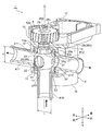
- FIG. 1 The perspective view which shows the whole structure of one Embodiment of the flow-path switching valve (three-way valve) which concerns on this invention.
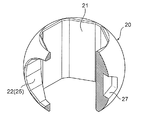
- the fragmentary longitudinal cross-section perspective view of the flow-path switching valve shown by FIG. The perspective view which shows the valve body of FIG.
- the partial notch which shows the valve body of FIG. 2 (The central angle 90 degree part is notched by planar view) perspective view.
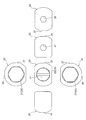
- 3A and 6B are six-side views of the valve body in FIGS.
- FIG. 7 is a partially cutaway perspective view showing another example of the valve body of the flow path switching valve shown in FIG. 1 (the central angle 90 ° portion is cut away in plan view).
- FIG. 7B is a six-sided view of the valve body of FIGS.
- FIG. 1 is a perspective view showing the overall configuration of an embodiment of a flow path switching valve according to the present invention
- FIG. 2 is a partial longitudinal sectional perspective view of the flow path switching valve shown in FIG. 3A and 3B are views showing the valve body of FIG. 2
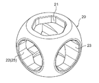
- FIG. 3A is a perspective view
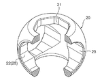
- FIG. 3B is a partially cutaway (a central angle 90 ° portion is cutout in plan view) perspective view
- FIG. It is a 6th page figure of the valve body of 3A and B.
- FIG. 1 is a perspective view showing the overall configuration of an embodiment of a flow path switching valve according to the present invention
- FIG. 2 is a partial longitudinal sectional perspective view of the flow path switching valve shown in FIG. 3A and 3B are views showing the valve body of FIG. 2
- FIG. 3A is a perspective view
- FIG. 3B is a partially cutaway (a central angle 90 ° portion is cutout in plan view) perspective view
- FIG. It is a 6th page figure of the valve body of 3
- the flow path switching valve 1 of the illustrated embodiment is used as, for example, a rotary three-way valve that switches a flow path of a fluid flowing in an engine room of an automobile in multiple directions, and basically includes a valve chamber 11.
- a valve body 10, a ball-shaped valve body (also referred to as a ball valve body) 20 rotatably disposed in the valve chamber 11, and a valve body 20 are rotated to rotate around a rotation axis (center line) O.
- the motor 8 is arranged from the rear part to the upper part of the main body 10, and the rotation drive part 5 is composed of a drive gear 9 and the like.
- the valve body 10 and the rotation drive unit 5 are formed integrally.
- a rotation axis (axis extending in the vertical direction) O of the valve body 20 accommodated in the valve chamber 11 is coaxial with a center line of an inlet p10 and a valve shaft 28 described later.
- the valve body 10 is composed of a square tubular base member 12 with a ceiling portion 12a made of, for example, a synthetic resin or metal, and a holder member 15, and the base member 12 is laid down in a cylindrical shape.
- a valve chamber 11 is formed, and a lateral outlet (entrance / exit) p11 and an outlet (entrance / exit) p12 that open to the valve chamber 11 are provided on the left and right sides, respectively.
- Ports # 11 and # 12 made of pipe joints are integrally connected to the outer periphery of the base member 12 so as to communicate with the outlets p11 and p12.
- the ceiling portion 12 a of the base member 12 is provided with a fitting insertion hole 13 through which a valve shaft 28 (an intermediate body portion 28 b) connected to the valve body 20 is inserted, and left and right of the fitting insertion hole 13.
- a valve shaft 28 an intermediate body portion 28 b
- the fitting insertion hole 13 slightly to the left and right of the portion where the step portion 28s between the lower engagement portion 28a and the intermediate body portion 28b of the valve shaft 28, which will be described later, is contacted and locked.
- Protrusions 14a and 14b for positioning of the annular sheet members 31 and 32 are provided so as to project substantially downward (downward) (see also FIG. 5).
- a holder member 15 having a port # 10 made of a pipe joint provided with a vertical inlet (inlet / outlet) p10 that opens into the valve chamber 11 is ultrasonically welded and screwed.
- the inner fitting is fixed by press fitting, caulking, etc. (ultrasonic welding in the illustrated example).
- valve body 10 is provided with an inlet p10 opened at the bottom of the valve chamber 11, and outlets (side inlet / outlet) p11, p12 opened at the side of the valve chamber 11 are 180. They are provided at an angle interval of ° (in other words, so as to face the opposite side with respect to the rotation axis O of the valve body 20).
- a motor case portion 16 that houses a motor 8 that constitutes the rotation drive portion 5 for rotating the valve body 20 (the valve shaft 28 connected to the valve body 20) is integrally formed at the rear portion of the base member 12 of the valve body 10.
- a gear case portion 17 that accommodates a drive gear 9 that is connected to the motor 8 and transmits the rotational force of the motor 8 to the valve shaft 28 is integrally formed on the upper portion (the upper surface side of the ceiling portion 12a). Is formed.
- the valve body 20 is made of, for example, synthetic resin, metal, or the like, and in order to selectively communicate the inlet p10 and the two outlets p11 and p12 provided in the valve body 10, in other words, the inlet p10 and In order to selectively switch the communication state of the two outlets p11 and p12, a flow path (internal flow path) 25 is provided inside.
- the internal flow path 25 is configured by a through hole that penetrates the valve body 20 from the lower part to the side part, and the lower opening always communicates with the inlet p10, and the side opening has two outlets. It is made to communicate with either p11 or p12 alternatively.
- the valve body 20 has a substantially hexagonal cross section that penetrates the valve body 20 in the vertical direction (the direction of the rotation axis O of the valve body 20).
- the vertical through-hole 21 upper and lower end openings are substantially hexagonal
- the horizontal hole 22 having a substantially hexagonal cross section that joins from the outer periphery (side part) of the valve body 20 to the center of the vertical through-hole 21. (In a direction orthogonal to the rotation axis O of the valve body 20).
- the vertical through hole 21 (the lower opening thereof) is always in communication with the inlet p10, and the lateral hole 22 (the side opening) is selectively in communication with one of the two outlets p11 and p12.
- the lower half of the vertical through hole 21 and the horizontal hole 22 form the internal flow path 25 (inside the valve body 20) having a reverse L-shape when viewed from the side.
- valve body 20 on the outer periphery (outer peripheral seal surface) of the valve body 20, specifically, on the back side of the side opening of the lateral hole 22 and the lateral side of the side opening of the lateral hole 22 on the outer periphery of the valve body 20, 11 are provided with hexagonal holes (hexagonal concave holes in side view) 26 and 27 as rotation engaging portions for rotating and installing the valve body 20 (detailed later).
- hexagonal holes hexagonal concave holes in side view
- a stepped valve shaft 28 (a lower part of the lower engaging portion 28a) for transmitting the rotational force of the motor 8 to the valve body 20 is connected to the valve body 20 (upper part of the vertical through hole 21).
- the valve shaft 28 has a shape complementary to the vertical through hole 21 of the valve body 20 from the lower side (that is, a substantially hexagonal cross section). Or a lower engaging portion 28a that is slightly smaller than the vertical through hole 21, an intermediate body portion 28b that is slightly smaller and circular in cross section than the lower engaging portion 28a, and an outer diameter that is substantially the same as that of the intermediate body portion 28b and a substantially hexagonal cross section.
- the upper connecting portion 28c and a circumferential positioning D-cut convex portion 28d projecting on the upper connecting portion 28c are configured so that the lower engaging portion 28a (the lower portion) of the vertical through hole 21 is formed.
- the intermediate body portion 28b is inserted into (inserted into) the insertion hole 13 of the valve body 10, and the upper connection portion 28c is located above the insertion hole 13 (on the upper surface side of the ceiling portion 12a). ) To protrude.
- An O-ring 29 as a sealing member is interposed in two stages in the intermediate body portion 28b (annular groove formed on the outer periphery thereof) that is rotatably inserted into the fitting insertion hole 13.
- valve body 20 By fitting the lower engagement portion 28 a into the vertical through hole 21, the valve body 20 is engaged with the valve shaft 28 so as not to rotate relative to the rotation axis O, and the valve shaft 28 and the valve body 20 are engaged with each other. It is designed to rotate as a unit.
- a step portion 28s formed between the lower engaging portion 28a and the intermediate body portion 28b in the valve shaft 28 is in contact with the periphery of the fitting hole 13 in the ceiling portion 12a of the valve body 10 (base member 12 thereof).
- the drive gear 9 of the rotation drive unit 5 is externally fitted and fixed to the upper connecting portion 28c protruding from the insertion hole 13 by press fitting, caulking, etc. ) And the drive gear 9 (the lower surface thereof) sandwich the ceiling portion 12a of the valve body 10 so that the valve shaft 28 is rotatably supported with respect to the valve body 10 (without moving up and down). .
- valve shaft 28 can be inserted through the vertical through hole 21 in the vertical direction (rotation axis O direction). (Details later).
- Annular sheet members 31 and 32 are arranged.
- a pair of seat members is disposed so as to be opposed to the rotation axis O of the valve body 20 so as to correspond to the pair of left and right outlets p ⁇ b> 11 and p ⁇ b> 12.
- 31 and 32 are disposed, and the valve body 20 is disposed between the pair of sheet members 31 and 32 (inside) so as to be freely slidable.
- the portion around the opening on the inner periphery (surface) is configured by a curved surface (a part of a concave spherical surface) and is in contact with the outer peripheral seal surface (curved surface) of the valve body 20 when the flow path is formed.
- the inner peripheral sealing surface is squeezed.
- the height H in the vertical direction (rotation axis O direction) of the valve body 20 disposed between the pair of sheet members 31 and 32 is equal to or less than the distance L between the sheet members 31 and 32. Or it is made slightly smaller (detailed later).
- O-rings (elastic members) 33 and 34 as sealing members made of an elastic material such as rubber are interposed (in a compressed state) in the annular groove formed on the (outlet p12 side surface). ing. Due to the elastic force (repulsive force) of the O-rings 33 and 34, the seat members 31 and 32 (the inner peripheral seal surface thereof) are pressed against the valve body 20 (the outer peripheral seal surface) side. The body 20 and each of the outlets p11 and p12 are hermetically sealed (sealed).
- the flow path switching valve (three-way valve) 1 having such a configuration, when the valve body 20 is rotated in the valve chamber 11 by the rotary drive unit 5 including the motor 8, the drive gear 9, and the like, the interior provided in the valve body 20 is provided. Through the flow path 25, the communication state of the inlet p10 and the two outlets p11 and p12 provided in the valve body 10 is selectively switched.
- the inlet p10 provided at the bottom of the valve body 10 and the outlet p11 provided at the left are (the lower half of the vertical through hole 21 and the horizontal hole).
- a communication mode via a first communication state
- Two modes of a mode (second communication state) communicating with each other are selectively taken.
- the opening of the seat member 32 corresponding to the right outlet p12 is closed by the valve body 20 (the outer peripheral seal surface thereof) (here, the portion where the hexagonal hole 26 is formed), and the outlet p12
- the fluid that has flowed upward from the inlet p10 flows through the internal channel 25 of the valve body 20 and flows out only from the left outlet p11.
- the opening of the seat member 31 corresponding to the left outlet p11 is closed by the valve body 20 (the outer peripheral seal surface thereof) (here, the portion where the hexagonal hole 26 is formed)
- the flow path connected to the outlet p11 is blocked, and the fluid that flows upward from the inlet p10 flows out of only the right outlet p12 through the internal flow path 25 of the valve body 20.
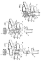
- FIG. 5 and 6 are diagrams for explaining the assembly procedure of the flow path switching valve shown in FIG. 1.
- FIG. 5 shows the procedure for installing the valve body in the valve chamber.
- FIG. 6 shows the valve shaft in the valve body. It is a figure explaining the procedure to support and fix.
- O-rings 33 and 34 are attached to the respective seat members 31 and 32 (annular concave grooves thereof) (procedure 1), and the valve body 10 is Before assembling the holder member 15 to the base member 12 (the lower end opening thereof), the seat members 31 and 32 with the O-rings 33 and 34 are inserted into the inside (that is, inside the valve chamber 11) through the lower end opening of the base member 12. ) (Around the left and right outlets p11, p12) (procedure 2).
- the projections 14a and 14b provided on the ceiling portion 12a of the base member 12 are used to align the seat members 31 and 32 in the valve chamber 11, and the interval between the seat members 31 and 32 is determined by the valve
- the height of the body 20 is set to be equal to or higher than the height in the vertical direction (direction of the rotation axis O).
- valve body 20 in which the internal flow path 25 composed of the vertical through hole 21 and the horizontal hole 22 is formed is laid down (that is, the posture in which the rotation axis direction of the valve body 20 is turned sideways or the valve body 20 is rotated).
- the axis line is oriented in the left-right direction
- the upper and lower end faces of the valve body 20 are oriented toward the left and right seat members 31, 32
- the hexagonal hole 26 is oriented downward
- the lower opening of the base member 12 (valve It is arranged in the inside (specifically, between the sheet members 31 and 32 arranged in the respective outlets p11 and p12 in the valve chamber 11) via the opening of the outer shape (outer diameter) of the body 20).
- a rotating jig G such as a hexagonal wrench having a hexagonal cross section at the tip is inserted from the lower opening of the base member 12, and the head is inserted into the hexagonal hole (rotating engagement portion) of the valve body 20.
- the rotation jig G is rotated by being fitted (engaged) with 26, thereby rotating the valve body 20 by about 90 ° between the sheet members 31 and 32 in the valve chamber 11 (extending in the vertical direction). (Rotate approximately 90 ° counterclockwise around the axis as viewed from below) (Procedure 4).
- the outer periphery (outer peripheral seal surface) of the valve body 20 slides on the left and right seat members 31 and 32 (inner peripheral seal surfaces thereof) and is disposed outside the seat members 31 and 32.
- the O-rings 33 and 34 are slightly compressed, and the outer periphery (outer peripheral seal surface) of the valve body 20 is pressed against the seat members 31 and 32 (inner peripheral seal surface thereof).
- the same rotating jig G as described above is inserted through the right port # 12 of the base member 12, and the head thereof is fitted into the hexagonal hole (rotating engagement portion) 27 of the valve body 20 ( The rotating jig G is rotated so that the valve body 20 is rotated about 90 ° between the sheet members 31 and 32 in the valve chamber 11 (viewed from the right around the axis extending in the left-right direction). (Rotate approximately 90 ° counterclockwise) (procedure 5).
- valve body 20 By rotating the valve body 20 around the two axes orthogonal to the rotation axis O between the seat members 31 and 32 in the valve chamber 11, the valve body 20 is in use in the valve chamber 11. (The posture in which the rotation axis O direction of the valve body 20 is vertical), and the vertical through hole 21 is directed in the vertical direction).
- an O-ring 29 is attached to the intermediate body portion 28 b of the valve shaft 28 (procedure 6), and rotation between the lower engagement portion 28 a of the valve shaft 28 and the vertical through hole 21 of the valve body 20.
- the stepped portion 28s between the lower engaging portion 28a of the valve shaft 28 and the intermediate body portion 28b is a ceiling portion 12a of the base member 12 of the valve body 10.
- the valve shaft 28 is inserted into the vertical through-hole 21 of the valve body 20 through the lower opening of the base member 12 until it contacts with (around the fitting insertion hole 13).
- the lower engaging portion 28a (lower portion) of the valve shaft 28 is inserted into the upper opening of the vertical through hole 21 (in a state in which the lower engaging portion 28a is engaged relatively non-rotatably around the rotation axis O),
- the trunk portion 28b is inserted into the insertion hole 13 of the valve body 10, and the upper coupling portion 28c protrudes upward from the insertion hole 13 (procedure 7).
- the holder member 15 is attached to the lower opening of the base member 12 by ultrasonic welding, screwing or the like, and the drive gear 9 of the rotary drive unit 5 is press-fitted into the upper coupling portion 28c of the valve shaft 28 protruding from the fitting insertion hole 13. It is attached by caulking or the like, and the valve shaft 28 is supported and fixed to the valve body 10 in a state where it can be rotated and kept from coming off (procedure 8). Furthermore, the flow path switching valve 1 is assembled by assembling the motor 8 and the like constituting the rotation drive unit 5 to the valve body 10.
- the interval between the sheet members 31 and 32 disposed in the valve chamber 11 is the vertical direction of the valve body 20.
- the height is greater than or slightly larger than the height of the rotation axis O direction, the insertion of the valve body 20 is performed even when the distance between the seat members 31 and 32 is slightly smaller than the vertical height of the valve body 20.
- the left and right O-rings 33 and 34 are compressed via the sheet members 31 and 32 (compressed with a force larger than the compression force applied to the O-rings 33 and 34 during normal use) so that the interval between the sheet members 31 and 32 is increased. You may arrange
- the valve main body 10 is Since it is not necessary to compress the O-rings 33 and 34 at the time of joining the base member 12 and the holder member 15 (such as ultrasonic welding), the crushing rate (crushing allowance) of the O-rings 33 and 34, etc. It becomes easy to manage the dimensions, suppresses bonding defects (for example, welding melt defects), and can effectively prevent liquid leakage, bonding (welding) cracks, and the like due to bonding defects.
- the configuration, shape, and the like of the internal flow path 25 formed in the valve body 20 may be changed as appropriate according to the intended use of the flow path switching valve 1 and the like.
- the valve body 20 in addition to the vertical through hole 21 and the horizontal hole 22 described above, the valve body 20 is vertically penetrated with respect to the rotation axis O and the vertical through path 21 and the horizontal hole 22 are provided.
- the aforementioned hexagonal hole (rotational engagement part) 27 is eliminated, but the lateral through hole 23 (end opening thereof) may be used as the same rotational engagement part as the aforementioned hexagonal hole 27.
- the aforementioned hexagonal hole 27 may be used as the same rotational engagement part as the aforementioned hexagonal hole 27.
- the lower opening of the vertical through hole 21 is a circular shape that is slightly larger than the hexagonal upper opening in plan view.
- the valve body 20 shown in FIGS. 7A, 7B and 8 is used, the valve body 20 is rotated about 180 ° to the inlet p10 provided at the bottom of the valve body 10 and the left part of the valve body 10.
- a mode (first communication state) in which only the provided outlet p11 communicates (via an internal flow path 25 including the lower half of the vertical through hole 21 and the horizontal hole 22) and the bottom of the valve body 10 are provided.
- 3 modes in the mode of communication (through the path 25) (third communication state) There has been adapted to be taken selectively.
- the cross-sectional shapes of the vertical through hole 21, the horizontal hole 22, the horizontal through hole 23, and the hexagonal holes 26 and 27 as the rotation engaging portions formed in the valve body 20 can be selected as appropriate.
- the cross-sectional shape of the vertical through hole 21 and the horizontal through hole 23 may be a polygon or an ellipse other than a hexagon
- the side opening of the horizontal hole 22 is a polygon, an ellipse, or a circle other than a hexagon.
- the hexagonal holes 26 and 27 may be polygonal or elliptical holes other than hexagonal holes.
- the number and arrangement of the inlets and outlets (inlet and outlet) formed in the valve body 10 can be changed as appropriate according to the application location of the flow path switching valve 1 and the like.
- the inlet p10 is opened at the bottom of the valve chamber 11, and the two outlets p11, p12 are opened at an angular interval of 180 ° on the side of the valve chamber 11.
- the three-way valve has been described as an example.For example, a two-way valve in which the bottom side inlet is omitted and one of the side outlets is used as an inlet, or an inlet opened in the valve chamber, Needless to say, four or more switching valves may be used in which the number of outlets and the arrangement configuration are changed.
- valve shaft 28 is attached to the valve body 10 by being inserted into the valve body 20 (the longitudinal through hole 21 thereof) from the lower side (the lower end opening side of the base member 12).
- the configuration of the flow path switching valve 2 as shown in FIG. 9 may be adopted, and the valve shaft 28 may be assembled to the valve body 10 from the upper side.
- the lower engaging portion 28a of the valve shaft 28 has a smaller diameter than the intermediate body portion 28b and the upper connecting portion 28c, and a step 28t between the lower engaging portion 28a and the intermediate body portion 28b is formed.
- the valve shaft 28 is inserted from the upper side (the ceiling portion 12a side of the base member 12 of the valve body 10) until it is contacted and locked to the inner hook-shaped hooking portion 13a provided in the lower inner periphery of the insertion hole 13.
- the lower engagement portion 28a (lower portion) of the valve shaft 28 is engaged with the upper opening of the vertical through hole 21 of the valve body 20 (non-rotatably around the rotation axis O). May be fitted).
- valve body having the configuration shown in FIGS. 7A, 7B and 8 (the configuration having the lateral through hole 23) is employed, but shown in FIGS. 3A, 3B and 4.
- a valve body having a configuration may be used.
- the flow path switching valve of the above embodiment is used for switching the flow path in an engine room or the like (such as an engine cooling circuit or an electronic device cooling circuit) in a vehicle.
- an engine room or the like such as an engine cooling circuit or an electronic device cooling circuit
- it may be used for path switching.
Landscapes
- Engineering & Computer Science (AREA)
- General Engineering & Computer Science (AREA)
- Mechanical Engineering (AREA)
- Multiple-Way Valves (AREA)
- Taps Or Cocks (AREA)
Abstract
Oリングの潰し率(潰し代)等の寸法管理を容易に行い得るとともに、接合不良を可及的に抑えることのできる流路切換弁及びその組立方法を提供する。弁体20の回転軸線O方向高さHは、弁室11の側部に開口せしめられた2つの流出口p11、p12に配置されたシート部材31、32同士の間隔L以下とされる。
Description
本発明は、流路切換弁及びその組立方法に係り、例えばボール状の弁体(ボール弁体)を弁室内で回転摺動させることにより流路を切り換えるロータリー形の流路切換弁に関する。
この種の従来の流路切換弁として、流入路と流出路とを有し弾性体からなる弁体(ボール弁体)と、該弁体が回転可能に収容される弁室と、該弁室に連通する入口流路及び複数の出口流路とを有する弁本体(弁ケース)とを備え、前記流入路が常時前記入口流路に連通し、前記弁体の回転動作によって、前記流出路が前記複数の出口流路のいずれかに択一的に連通するもの(ボールバルブ)が知られている(例えば、下記特許文献1参照)。
上記特許文献1に所載の従来の流路切換弁(ボールバルブ)では、弾性体からなる弁体が弁本体に押し付けられた状態で弁室に回転可能に収容されることにより、弁体の流入路が弁本体の下部に設けられた入口流路に常時連通するとともに、当該弁体の回転動作によって、弁体の流出路が弁本体の側部に設けられた複数の出口流路のいずれかに択一的に連通するようになっている。
また、上記従来の流路切換弁に対して、弁室に収容された弁体と弁本体の側部に設けられた各流路との間のシール性を確保すべく、それらの間にテフロン(登録商標)製の円環状のシート部材を装着するとともに、シート部材と弁本体との間に、シート部材を弁体に押し付けるゴム製のOリングを介装したものも既に知られている。
ところで、上記した如くの従来の流路切換弁では、前記弁本体を、一側部が開口した基体部材とホルダ部材との2部品構成(分割構成)とし、基体部材の内部に弁体等を設置した後、基体部材の側部開口にホルダ部材を超音波溶着等で接合することにより、前記弁体等を弁本体(の弁室)に組み付けている。
そのため、上記従来の流路切換弁では、弁本体を構成する基体部材とホルダ部材との接合時(超音波溶着時)に、弾性体からなるOリングの圧縮を伴うことになるので、次のような懸念があった。
すなわち、例えば超音波溶着による溶けのばらつきが大きくなり、その溶着部の溶け込み量がOリングの潰し率(潰し代)に大きく起因してしまい、Oリングの潰し率(潰し代)の設計ばらつきが大きくなるおそれがある。また、弾性体からなるOリングの反発力からホルダ部材の基体部材に対する傾きが発生しやすく、寸法管理が難しくなる。また、例えば超音波溶着の溶け込み不良等の接合不良によって、液漏れが発生するおそれもある。
本発明は、前記事情に鑑みてなされたものであって、その目的とするところは、Oリングの潰し率(潰し代)等の寸法管理を容易に行い得るとともに、接合不良を可及的に抑えることのできる流路切換弁及びその組立方法を提供することにある。
上記する課題を解決するために、本発明に係る流路切換弁は、内部に弁室が形成されるとともに、該弁室に開口せしめられた複数の入出口が設けられた弁本体と、前記弁室内に回転自在に配在され且つ内部に流路が形成された弁体と、前記弁体と前記入出口との間を封止すべく、前記弁体と前記入出口との間に配置されたシート部材と、前記シート部材を前記弁体に押し付けるべく、前記シート部材と前記弁本体との間に配置された弾性部材と、前記弁体を回転軸線周りで回転させる回転駆動部と、を備え、前記弁体を回転させることにより、前記複数の入出口の連通状態が前記弁体の前記流路を通じて選択的に切り換えるようにされた流路切換弁であって、前記複数の入出口は、少なくとも前記弁室の側部に開口せしめられた2つの側部入出口を含み、前記弁体の回転軸線方向高さは、前記2つの側部入出口に配置された前記シート部材同士の間隔以下とされていることを特徴としている。
好ましい態様では、前記弁体の回転軸線方向高さは、前記弾性部材を所定圧で圧縮した状態での前記シート部材同士の間隔以下とされる。
別の好ましい態様では、前記弁本体は、前記2つの側部入出口が設けられるとともに、回転軸線方向の一端に前記弁体の外形以上の開口が設けられた基体部材と、該基体部材の前記開口に連結固定されたホルダ部材との分割構成とされる。
他の好ましい態様では、前記弁体の外周の少なくとも2箇所に、前記弁室内で前記弁体を所定方向に回転させて設置するための回転係合部が設けられる。
更に好ましい態様では、前記弁体には、該弁体を回転軸線方向に貫通するとともに、前記回転駆動部の回転力を前記弁体に伝達する弁軸が相対回転不能に係合せしめられる縦貫通穴が設けられる。
更に好ましい態様では、前記縦貫通穴は、前記弁軸を回転軸線方向に挿通可能とされる。
更に好ましい態様では、前記弁体の外周から前記縦貫通穴に合流する横穴が形成される。
更に好ましい態様では、前記弁体の外周から前記縦貫通穴に合流する横穴及び前記弁体を回転軸線に対して垂直に貫通するとともに前記縦貫通穴に交差して合流する横貫通穴の少なくとも一方が形成されるとともに、前記横穴及び前記横貫通穴の少なくとも一方に前記回転係合部が設けられる。
更に好ましい態様では、前記弁軸は、前記縦貫通穴並びに前記弁本体に設けられた嵌挿穴に挿通されるとともに、前記嵌挿穴から突出する部分に、前記回転駆動部を構成する駆動ギアが固定される。
更に好ましい態様では、前記弁軸の外周に、前記嵌挿穴周りに接当係止される段差部が設けられる。
更に好ましい態様では、前記嵌挿穴に内鍔状掛止部が設けられるとともに、前記弁軸の外周に、前記内鍔状掛止部に接当係止される段差が設けられる。
また、本発明に係る流路切換弁の組立方法は、内部に弁室が形成されるとともに、該弁室に開口せしめられた複数の入出口が設けられた弁本体と、前記弁室内に回転自在に配在され且つ内部に流路が形成された弁体と、前記弁体と前記入出口との間を封止すべく、前記弁体と前記入出口との間に配置されたシート部材と、前記シート部材を前記弁体に押し付けるべく、前記シート部材と前記弁本体との間に配置された弾性部材と、前記弁体を回転軸線周りで回転させる回転駆動部と、を備え、前記弁体を回転させることにより、前記複数の入出口の連通状態が前記弁体の前記流路を通じて選択的に切り換えるようにされた流路切換弁の組立方法であって、少なくとも前記弁室の側部に開口せしめられた2つの側部入出口に前記弾性部材及び前記シート部材を配置するとともに、前記2つの側部入出口に配置された前記シート部材同士の間に前記弁体を前記回転軸線方向を横向きにした姿勢で配置するステップと、前記弁室における前記シート部材同士の間で前記弁体を少なくとも前記回転軸線に直交する2つの軸線周りで回転させ、前記弁体を前記回転軸線方向を縦向きにした姿勢で設置するステップと、前記回転駆動部の回転力を前記弁体に伝達する弁軸を前記弁体に連結するステップと、を含むことを特徴としている。
好ましい態様では、前記弁軸を前記弁体に連結するステップにおいて、前記弁体を回転軸線方向に貫通する縦貫通穴に前記弁軸を通し、該縦貫通穴に前記弁軸を相対回転不能に係合せしめるとともに、前記弁本体に設けられた嵌挿穴に前記弁軸を挿通させ、前記弁軸における前記嵌挿穴から突出する部分に、前記回転駆動部を構成する駆動ギアを固定する。
更に好ましい態様では、前記弁軸の外周に設けられた段差部が前記嵌挿穴周りに接当係止するまで、前記弁軸を前記縦貫通穴及び前記嵌挿穴に挿通させる。
別の好ましい態様では、前記弁軸を前記弁体に連結するステップにおいて、前記弁本体に設けられた嵌挿穴に前記弁軸を挿通させるとともに、前記弁体を回転軸線方向に貫通する縦貫通穴に前記弁軸を通し、該縦貫通穴に前記弁軸を相対回転不能に係合せしめ、前記弁軸における前記嵌挿穴から突出する部分に、前記回転駆動部を構成する駆動ギアを固定する。
更に好ましい態様では、前記弁軸の外周に設けられた段差が前記嵌挿穴に設けられた内鍔状掛止部に接当係止するまで、前記弁軸を前記嵌挿穴に挿通させる。
本発明によれば、例えば、弁本体を基体部材とホルダ部材との2部品構成(分割構成)とした場合でも、前記弁本体を構成する基体部材とホルダ部材との接合時(超音波溶着時等)に前記弾性部材の圧縮を行う必要がないので、弾性部材の潰し率(潰し代)等の寸法管理が容易となるとともに、接合不良(例えば溶着溶け不良)が抑えられ、接合不良に起因する液漏れや接合部(溶着部)割れ等を効果的に阻止することが可能となる。
以下、本発明の実施形態を図面を参照して説明する。
なお、各図において、部材間に形成される隙間や部材間の離隔距離等は、発明の理解を容易にするため、また、作図上の便宜を図るため、誇張して描かれている場合がある。また、本明細書において、上下、左右、前後等の位置、方向を表わす記述は、図1及び図2の方向矢印表示を基準としており、実際の使用状態での位置、方向を指すものではない。
<流路切換弁1の構成・動作>
図1は、本発明に係る流路切換弁の一実施形態の全体構成を示す斜視図、図2は、図1に示される流路切換弁の部分縦断面斜視図である。また、図3A、Bは、図2の弁体を示す図であり、図3Aは斜視図、図3Bは部分切欠(平面視で中心角90°部分が切欠)斜視図、図4は、図3A、Bの弁体の六面図である。
図1は、本発明に係る流路切換弁の一実施形態の全体構成を示す斜視図、図2は、図1に示される流路切換弁の部分縦断面斜視図である。また、図3A、Bは、図2の弁体を示す図であり、図3Aは斜視図、図3Bは部分切欠(平面視で中心角90°部分が切欠)斜視図、図4は、図3A、Bの弁体の六面図である。
図示実施形態の流路切換弁1は、例えば自動車のエンジンルーム内等を流れる流体の流路を多方向に切り換えるロータリー形の三方弁として使用されるもので、基本的に、弁室11を有する弁本体10と、弁室11内に回転自在に配在されたボール状の弁体(ボール弁体ともいう)20と、弁体20を回転軸線(中心線)O周りで回転させるべく、弁本体10の後部から上部にかけて配置されるモータ8、駆動ギア9等からなる回転駆動部5と、を備えている。ここでは、弁本体10と回転駆動部5とは一体的に形成されている。なお、弁室11内に収容された弁体20の回転軸線(上下方向に延びる軸線)Oは、後述する流入口p10や弁軸28の中心線と同軸とされている。
前記弁本体10は、例えば合成樹脂製や金属製とされた天井部12a付き角筒状の基体部材12とホルダ部材15とで構成されており、前記基体部材12は、内部に横倒し円筒状の弁室11が形成されるとともに、その左部及び右部にそれぞれ、前記弁室11に開口する横向きの流出口(入出口)p11及び流出口(入出口)p12が設けられている。前記基体部材12の外周には、流出口p11、p12に連通するように管継手からなるポート#11、#12が一体的に連結されている。また、前記基体部材12の天井部12aには、弁体20に連結される弁軸28(の中間胴部28b)が挿通される嵌挿穴13が設けられるとともに、その嵌挿穴13の左右(より詳しくは、嵌挿穴13周りにおいて後述する弁軸28の下部係合部28aと中間胴部28bとの間の段差部28sが接当係止される部分より若干左右寄り)に、後述する円環状のシート部材31、32の位置決め用の突起14a、14bが略半周にわたって(下向きに)突設されている(図5も併せて参照)。基体部材12の下端開口には、前記弁室11に開口する縦向きの流入口(入出口)p10が設けられた管継手からなるポート#10を持つホルダ部材15が、超音波溶着、ねじ止め、圧入、かしめ等(図示例では、超音波溶着)により内嵌固定されている。
すなわち、弁本体10には、弁室11の底部に開口せしめられた流入口p10が設けられるとともに、弁室11の側部に開口せしめられた流出口(側部入出口)p11、p12が180°の角度間隔をあけて(言い換えれば、弁体20の回転軸線Oに対して反対側に対向するように)設けられている。
前記弁本体10の基体部材12の後部には、前記弁体20(に連結される弁軸28)を回転させるための回転駆動部5を構成するモータ8を収容するモータケース部16が一体的に形成され、その上部(天井部12aの上面側)には、モータ8に連結されて当該モータ8の回転力を弁軸28に伝達する駆動ギア9等を収容するギアケース部17が一体的に形成されている。
前記弁体20は、例えば合成樹脂や金属等から作製され、前記弁本体10に設けられた流入口p10及び2つの流出口p11、p12を選択的に連通させるべく、言い換えれば、流入口p10及び2つの流出口p11、p12の連通状態を選択的に切り換えるべく、内部に流路(内部流路)25が設けられている。
前記内部流路25は、弁体20内をその下部から側部まで貫通する貫通穴で構成されており、その下部開口が流入口p10と常時連通するとともに、その側部開口が2つの流出口p11、p12のいずれかと択一的に連通するようにされている。
詳細には、図3A、B及び図4を参照すればよく分かるように、弁体20には、当該弁体20を上下方向(弁体20の回転軸線O方向)に貫通する断面略六角形(つまり、上下の端部開口は略六角形)の縦貫通穴21が形成されるとともに、弁体20の外周(側部)から縦貫通穴21の中央に合流する断面略六角形の横穴22が(弁体20の回転軸線Oに直交する方向に)形成されている。
前記縦貫通穴21(の下部開口)は流入口p10と常時連通し、前記横穴22(の側部開口)は2つの流出口p11、p12のいずれかと択一的に連通するようになっており、前記縦貫通穴21の下半部と前記横穴22とによって、側面視逆L字状の前記内部流路25が(弁体20内に)形成される。
また、前記弁体20の外周(外周シール面)、具体的には、弁体20の外周における横穴22の側部開口の裏側及び横穴22の側部開口の横側には、組立時に弁室11内で弁体20を回転させて設置するための回転係合部としての六角穴(側面視六角形の凹穴)26、27が設けられている(後で詳述)。
前記弁体20(の縦貫通穴21の上部)には、モータ8の回転力を当該弁体20に伝達する段付きの弁軸28(の下部係合部28aの下部)が連結されている。
詳しくは、図2と併せて図6を参照すればよく分かるように、前記弁軸28は、下側から、前記弁体20の縦貫通穴21と相補的な形状(つまり、断面略六角形)もしくは縦貫通穴21より若干小形の下部係合部28aと、下部係合部28aより若干小形かつ断面円形の中間胴部28bと、中間胴部28bとほぼ同じ外径かつ断面略六角形の上部連結部28cと、上部連結部28c上に突設される周方向位置決め用のDカット凸部28dとで構成されており、前記下部係合部28a(の下部)が前記縦貫通穴21の上部開口に嵌挿され、前記中間胴部28bが前記弁本体10の嵌挿穴13に挿通(内挿)され、前記上部連結部28cは前記嵌挿穴13から上側(天井部12aの上面側)に突出するようになっている。前記嵌挿穴13に回動自在に挿通される前記中間胴部28b(の外周に形成された環状溝)には、シール部材としてのOリング29が二段介装されている。
下部係合部28aが縦貫通穴21に嵌挿されることにより、前記弁体20が前記弁軸28に回転軸線O周りで相対回転不能に係合せしめられ、弁軸28と弁体20とが一体となって回転するようになっている。
また、前記弁軸28における下部係合部28aと中間胴部28bとの間に形成される段差部28sは、弁本体10(の基体部材12)の天井部12aにおける嵌挿穴13周りに接当係止されるとともに、前記嵌挿穴13から突出する前記上部連結部28cに、回転駆動部5の駆動ギア9が圧入・かしめ等により外嵌固定されており、前記段差部28s(の上面)と前記駆動ギア9(の下面)とで弁本体10の天井部12aを挟持するようにして、弁軸28が弁本体10に対して(上下動せずに)回転可能に支持されている。
なお、前記のように、弁体20の縦貫通穴21は弁軸28の外形より大きく設定されているので、弁軸28は縦貫通穴21を上下方向(回転軸線O方向)に挿通可能となっている(後で詳述)。
また、弁本体10の内壁面(弁室11の左右の端面)における各流出口p11、p12周りには、テフロン(登録商標)等から作製され、各流出口p11、p12に対応する開口を持つ円環状のシート部材31、32が配在されている。つまり、弁本体10の弁室11内において、前記した左右一対の流出口p11、p12に対応して弁体20の回転軸線Oに対して反対側に対向配置されるように、一対のシート部材31、32が配在され、その一対のシート部材31、32の間(内側)に、前記弁体20が回転摺動自在に配在されている。各シート部材31、32において、内周(面)における前記開口周りの部分は曲面(凹状の球面の一部)で構成され、流路形成時に弁体20の外周シール面(曲面)と対接せしめられる内周シール面とされる。一方で、本例では、前記一対のシート部材31、32の間に配在される弁体20の上下方向(回転軸線O方向)の高さHは、シート部材31、32同士の間隔L以下もしくはそれより若干小さくされている(後で詳述)。
また、各シート部材31、32と弁本体10(の各流出口p11、p12周り)との間(具体的には、シート部材31の左面(流出口p11側の面)及びシート部材32の右面(流出口p12側の面)に形成された環状凹溝)には、ゴム等の弾性材料により構成されたシール部材としてのOリング(弾性部材)33、34が(圧縮状態で)介装されている。このOリング33、34の弾性力(反発力)によって各シート部材31、32(の内周シール面)が弁体20(の外周シール面)側に密着するように押し付けられ、これにより、弁体20と各流出口p11、p12との間が気密的にシール(封止)されている。
かかる構成の流路切換弁(三方弁)1では、モータ8、駆動ギア9等からなる回転駆動部5によって弁体20が弁室11内で回転されると、弁体20に設けられた内部流路25を通じて、弁本体10に設けられた流入口p10及び2つの流出口p11、p12の連通状態が選択的に切り換えられる。
詳細には、前記弁体20の180°程度の回転により、弁本体10の底部に設けられた流入口p10と左部に設けられた流出口p11が(縦貫通穴21の下半部と横穴22からなる内部流路25を介して)連通するモード(第1連通状態)と、弁本体10の底部に設けられた流入口p10と右部に設けられた流出口p12が(縦貫通穴21の下半部と横穴22からなる内部流路25を介して)連通するモード(第2連通状態)の2つのモードが選択的にとられるようになっている。
前記第1連通状態では、右側の流出口p12に対応したシート部材32の開口が弁体20(の外周シール面)(ここでは、六角穴26が形成された部分)によって閉塞され、流出口p12に繋がる流路が遮断され、流入口p10から上向きに流入した流体は、弁体20の内部流路25内を通って左側の流出口p11のみから流出する。一方で、前記第2連通状態では、左側の流出口p11に対応したシート部材31の開口が弁体20(の外周シール面)(ここでは、六角穴26が形成された部分)によって閉塞され、流出口p11に繋がる流路が遮断され、流入口p10から上向きに流入した流体は、弁体20の内部流路25内を通って右側の流出口p12のみから流出する。
<流路切換弁1の組立方法>
前記した如くの構成を有する流路切換弁(三方弁)1の組立は、例えば以下の手順で行われる。図5及び図6は、図1に示される流路切換弁の組立手順を説明する図であり、図5は、弁室内に弁体を設置する手順、図6は、弁本体に弁軸を支持固定する手順を説明する図である。
前記した如くの構成を有する流路切換弁(三方弁)1の組立は、例えば以下の手順で行われる。図5及び図6は、図1に示される流路切換弁の組立手順を説明する図であり、図5は、弁室内に弁体を設置する手順、図6は、弁本体に弁軸を支持固定する手順を説明する図である。
前記流路切換弁1を組み立てるに当たっては、図5に示すように、まず、各シート部材31、32(の環状凹溝)にOリング33、34を装着し(手順1)、弁本体10を構成する基体部材12(の下端開口)にホルダ部材15を組み付ける前に、Oリング33、34付きのシート部材31、32を基体部材12の下端開口を介してその内部(つまり、弁室11内)(の左右の各流出口p11、p12周り)に設置する(手順2)。このとき、基体部材12の天井部12aに設けられた突起14a、14bを利用して、弁室11における各シート部材31、32の位置合わせを行い、シート部材31、32同士の間隔は、弁体20の上下方向(回転軸線O方向)の高さ以上もしくはそれより若干大きくされている。
次に、前記縦貫通穴21及び横穴22からなる内部流路25が形成された弁体20を、横倒し(つまり、弁体20の回転軸線方向を横向きにした姿勢、あるいは、弁体20の回転軸線が左右方向に向く姿勢であって、弁体20の上下の端面が左右のシート部材31、32に向く姿勢)かつ六角穴26が下側を向く姿勢で、基体部材12の下部開口(弁体20の外形(外径)以上の開口)を介してその内部(具体的には、弁室11内の各流出口p11、p12に配置されたシート部材31、32同士の間)に配置する(手順3)。
その状態で、例えば先端に断面六角形の頭部を持つ六角レンチ等の回転用冶具Gを基体部材12の下部開口から挿入し、その頭部を前記弁体20の六角穴(回転係合部)26に嵌め込んで(係合させて)当該回転用冶具Gを回転させ、これにより、弁体20を弁室11におけるシート部材31、32同士の間で約90°回転(上下方向に延びる軸線周りで、下から視て反時計回りに約90°回転)させる(手順4)。この弁体20の回転時において、弁体20の外周(外周シール面)は左右のシート部材31、32(の内周シール面)に摺動するとともに、シート部材31、32の外側に配されたOリング33、34は若干圧縮せしめられ、弁体20の外周(外周シール面)はシート部材31、32(の内周シール面)に圧接せしめられる。
次に、前記と同様の回転用冶具Gを基体部材12の右側のポート#12を介して挿入し、その頭部を前記弁体20の六角穴(回転係合部)27に嵌め込んで(係合させて)当該回転用冶具Gを回転させ、これにより、弁体20を弁室11におけるシート部材31、32同士の間で約90°回転(左右方向に延びる軸線周りで、右から視て反時計回りに約90°回転)させる(手順5)。
このように、弁室11におけるシート部材31、32同士の間で弁体20を回転軸線Oに直交する2つの軸線周りで回転させることにより、前記弁室11内で前記弁体20が使用時の姿勢(弁体20の回転軸線O方向を縦向きにした姿勢であって、縦貫通穴21を上下方向に向けた姿勢)で設置される。
次いで、図6に示すように、弁軸28の中間胴部28bにOリング29を装着し(手順6)、弁軸28の下部係合部28aと弁体20の縦貫通穴21との回転位置(回転軸線O回りの角度位置)を位置合わせした状態で、弁軸28の下部係合部28aと中間胴部28bとの間の段差部28sが弁本体10の基体部材12の天井部12a(における嵌挿穴13周り)に接当するまで、前記弁軸28を基体部材12の下部開口を介して弁体20の縦貫通穴21内に挿入する。これにより、前記弁軸28の下部係合部28a(の下部)は前記縦貫通穴21の上部開口に(回転軸線O周りで相対回転不能に係合せしめられた状態で)嵌挿され、中間胴部28bは弁本体10の嵌挿穴13に挿通されるとともに、上部連結部28cはその嵌挿穴13から上側に突出する(手順7)。
そして、基体部材12の下部開口にホルダ部材15を超音波溶着・ねじ止め等により取り付け、嵌挿穴13から突出した弁軸28の上部連結部28cに回転駆動部5の駆動ギア9を圧入・かしめ等により取り付けて当該弁軸28を弁本体10に回転可能かつ抜け止め保持された状態で支持固定する(手順8)。さらに、回転駆動部5を構成するモータ8等を弁本体10に組み付けることで、当該流路切換弁1が組み立てられる。
なお、前述の流路切換弁1では、弁室11内に弁体20をスムースに挿入するために、弁室11内に配置されたシート部材31、32同士の間隔が弁体20の上下方向(回転軸線O方向)の高さ以上もしくはそれより若干大きくされているが、前記シート部材31、32同士の間隔が弁体20の上下方向の高さより若干小さい場合でも、前記弁体20の挿入時に、シート部材31、32を介して左右のOリング33、34を圧縮(通常使用時にOリング33、34にかかる圧縮力より大きい力で圧縮)して当該シート部材31、32同士の間隔を押し拡げることによって、当該弁体20をシート部材31、32同士の間に配置しても良い。
以上で説明したように、本実施形態の流路切換弁1では、例えば、弁本体10を基体部材12とホルダ部材15との2部品構成(分割構成)とした場合でも、前記弁本体10を構成する基体部材12とホルダ部材15との接合時(超音波溶着時等)に前記Oリング33、34の圧縮を行う必要がないので、Oリング33、34の潰し率(潰し代)等の寸法管理が容易となるとともに、接合不良(例えば溶着溶け不良)が抑えられ、接合不良に起因する液漏れや接合部(溶着部)割れ等を効果的に阻止することが可能となる。
なお、弁体20の内部に形成される内部流路25の構成・形状等は、当該流路切換弁1の使用用途等に応じて、適宜に変更しても良いことは勿論である。
例えば、図7A、B及び図8に示される如くに、前述の縦貫通穴21及び横穴22に加えて、弁体20を回転軸線Oに対して垂直に貫通するとともに前記縦貫通路21及び横穴22に交差して合流する断面略六角形(つまり、側部開口が六角形)の横貫通穴23を形成しても良い。この場合、前述の六角穴(回転係合部)27は無くなるが、横貫通穴23(の端部開口)を、前述の六角穴27と同じ回転係合部として利用すればよい。なお、図7A、B及び図8に示される例では、縦貫通穴21の下部開口は、平面視六角形の上部開口より若干大きい円形とされている。図7A、B及び図8に示される弁体20を使用する場合、当該弁体20の180°程度の回転により、弁本体10の底部に設けられた流入口p10と弁本体10の左部に設けられた流出口p11のみが(縦貫通穴21の下半部と横穴22からなる内部流路25を介して)連通するモード(第1連通状態)と、弁本体10の底部に設けられた流入口p10と弁本体10の左右に設けられた流出口p11、p12の双方が(縦貫通穴21の下半部と横貫通穴23からなる内部流路25を介して)連通するモード(第2連通状態)と、弁本体10の底部に設けられた流入口p10と弁本体10の右部に設けられた流出口p12のみが(縦貫通穴21の下半部と横穴22からなる内部流路25を介して)連通するモード(第3連通状態)の3つのモードが選択的にとられるようになっている。
なお、必ずしも横穴22及び横貫通穴23の両方を設ける必要はなく、例えば、前述の横穴22に代えて図7A、B及び図8に示される如くの横貫通穴23を設けても良いことは詳述するまでも無い。
また、弁体20に形成される縦貫通穴21、横穴22、横貫通穴23、回転係合部としての六角穴26、27の断面形状は、適宜の形状を選択できることは言うまでも無い。例えば、縦貫通穴21や横貫通穴23の断面形状を、六角形以外の多角形や楕円形等としても良いし、横穴22の側部開口を、六角形以外の多角形や楕円形、円形等としても良い。また、組立時に弁室11内で弁体20を回転させられれば、六角穴26、27を、六角形以外の多角形や楕円形の穴等としても良い。
また、弁本体10に形成される入出口(流入口、流出口)の数や配置構成は、当該流路切換弁1の適用箇所等に応じて、適宜に変更できることは言うまでも無い。上記実施形態では、流路切換弁1として、弁室11の底部に流入口p10が開口せしめられ、弁室11の側部に2つの流出口p11、p12が180°の角度間隔をあけて開口せしめられた三方弁を例にとって説明したが、例えば、底部側の流入口を省略して側部の流出口の一方を流入口として使用した二方弁や、弁室に開口せしめられる流入口や流出口の数及び配置構成等を変更した四方以上の切換弁としても良いことは言うまでも無い。
また、上記実施形態では、弁軸28を下側(基体部材12の下端開口側)から弁体20(の縦貫通穴21)内に挿通させることによって弁本体10に取り付けているが、例えば、図9に示される如くの流路切換弁2の構成を採用し、当該弁軸28を上側から弁本体10に組み付けても良い。
すなわち、図9に示される如くに、弁軸28における下部係合部28aを中間胴部28bや上部連結部28cより小径とし、下部係合部28aと中間胴部28bとの間の段差28tが嵌挿穴13の下部内周に設けられた内鍔状掛止部13aに接当係止するまで、前記弁軸28を上側(弁本体10の基体部材12の天井部12a側)から嵌挿穴13に挿通し、これにより、弁軸28の下部係合部28a(の下部)を弁体20の縦貫通穴21の上部開口に(回転軸線O周りで相対回転不能に係合せしめられた状態で)嵌め込んでも良い。この場合、上部連結部28cに対して駆動ギア9を固定するときに、前記下部係合部28aと中間胴部28bとの間の段差28tが弁本体10(の基体部材12)に対する弁軸28の受け面となるので、前記駆動ギア9の固定が比較的容易となる。
なお、図9に示される例では、図7A、B及び図8に示される構成(横貫通穴23を有する構成)の弁体を採用しているが、図3A、B及び図4に示される構成の弁体を使用しても良いことは当然である。
また、上記実施形態の流路切換弁は、車両におけるエンジンルーム内等(エンジン冷却用回路や電子機器冷却用回路等)の流路切換用に使用されるものとしているが、例えば給湯設備における流路切換用に使用しても良いことは勿論である。
1 流路切換弁
5 回転駆動部
8 モータ
9 駆動ギア
10 弁本体
11 弁室
12 基体部材
12a 天井部
13 嵌挿穴
13a 内鍔状掛止部
15 ホルダ部材
20 弁体
21 縦貫通穴
22 横穴
23 横貫通穴
25 内部流路
26、27 六角穴(回転係合部)
28 弁軸
28a 下部係合部
28b 中間胴部
28c 上部連結部
28d Dカット凸部
28s 段差部
28t 段差
29 Oリング
31、32 シート部材
33、34 Oリング(弾性部材)
p10 流入口(入出口)
p11 流出口(側部入出口)
p12 流出口(側部入出口)
5 回転駆動部
8 モータ
9 駆動ギア
10 弁本体
11 弁室
12 基体部材
12a 天井部
13 嵌挿穴
13a 内鍔状掛止部
15 ホルダ部材
20 弁体
21 縦貫通穴
22 横穴
23 横貫通穴
25 内部流路
26、27 六角穴(回転係合部)
28 弁軸
28a 下部係合部
28b 中間胴部
28c 上部連結部
28d Dカット凸部
28s 段差部
28t 段差
29 Oリング
31、32 シート部材
33、34 Oリング(弾性部材)
p10 流入口(入出口)
p11 流出口(側部入出口)
p12 流出口(側部入出口)
Claims (16)
- 内部に弁室が形成されるとともに、該弁室に開口せしめられた複数の入出口が設けられた弁本体と、前記弁室内に回転自在に配在され且つ内部に流路が形成された弁体と、前記弁体と前記入出口との間を封止すべく、前記弁体と前記入出口との間に配置されたシート部材と、前記シート部材を前記弁体に押し付けるべく、前記シート部材と前記弁本体との間に配置された弾性部材と、前記弁体を回転軸線周りで回転させる回転駆動部と、を備え、前記弁体を回転させることにより、前記複数の入出口の連通状態が前記弁体の前記流路を通じて選択的に切り換えるようにされた流路切換弁であって、
前記複数の入出口は、少なくとも前記弁室の側部に開口せしめられた2つの側部入出口を含み、前記弁体の回転軸線方向高さは、前記2つの側部入出口に配置された前記シート部材同士の間隔以下とされていることを特徴とする流路切換弁。 - 前記弁体の回転軸線方向高さは、前記弾性部材を所定圧で圧縮した状態での前記シート部材同士の間隔以下とされていることを特徴とする請求項1に記載の流路切換弁。
- 前記弁本体は、前記2つの側部入出口が設けられるとともに、回転軸線方向の一端に前記弁体の外形以上の開口が設けられた基体部材と、該基体部材の前記開口に連結固定されたホルダ部材との分割構成とされていることを特徴とする請求項1又は2に記載の流路切換弁。
- 前記弁体の外周の少なくとも2箇所に、前記弁室内で前記弁体を所定方向に回転させて設置するための回転係合部が設けられていることを特徴とする請求項1から3のいずれか一項に記載の流路切換弁。
- 前記弁体には、該弁体を回転軸線方向に貫通するとともに、前記回転駆動部の回転力を前記弁体に伝達する弁軸が相対回転不能に係合せしめられる縦貫通穴が設けられていることを特徴とする請求項4に記載の流路切換弁。
- 前記縦貫通穴は、前記弁軸を回転軸線方向に挿通可能とされていることを特徴とする請求項5に記載の流路切換弁。
- 前記弁体の外周から前記縦貫通穴に合流する横穴が形成されていることを特徴とする請求項5又は6に記載の流路切換弁。
- 前記弁体の外周から前記縦貫通穴に合流する横穴及び前記弁体を回転軸線に対して垂直に貫通するとともに前記縦貫通穴に交差して合流する横貫通穴の少なくとも一方が形成されるとともに、前記横穴及び前記横貫通穴の少なくとも一方に前記回転係合部が設けられていることを特徴とする請求項5又は6に記載の流路切換弁。
- 前記弁軸は、前記縦貫通穴並びに前記弁本体に設けられた嵌挿穴に挿通されるとともに、前記嵌挿穴から突出する部分に、前記回転駆動部を構成する駆動ギアが固定されていることを特徴とする請求項6に記載の流路切換弁。
- 前記弁軸の外周に、前記嵌挿穴周りに接当係止される段差部が設けられていることを特徴とする請求項9に記載の流路切換弁。
- 前記嵌挿穴に内鍔状掛止部が設けられるとともに、前記弁軸の外周に、前記内鍔状掛止部に接当係止される段差が設けられていることを特徴とする請求項9に記載の流路切換弁。
- 内部に弁室が形成されるとともに、該弁室に開口せしめられた複数の入出口が設けられた弁本体と、前記弁室内に回転自在に配在され且つ内部に流路が形成された弁体と、前記弁体と前記入出口との間を封止すべく、前記弁体と前記入出口との間に配置されたシート部材と、前記シート部材を前記弁体に押し付けるべく、前記シート部材と前記弁本体との間に配置された弾性部材と、前記弁体を回転軸線周りで回転させる回転駆動部と、を備え、前記弁体を回転させることにより、前記複数の入出口の連通状態が前記弁体の前記流路を通じて選択的に切り換えるようにされた流路切換弁の組立方法であって、
少なくとも前記弁室の側部に開口せしめられた2つの側部入出口に前記弾性部材及び前記シート部材を配置するとともに、前記2つの側部入出口に配置された前記シート部材同士の間に前記弁体を前記回転軸線方向を横向きにした姿勢で配置するステップと、
前記弁室における前記シート部材同士の間で前記弁体を少なくとも前記回転軸線に直交する2つの軸線周りで回転させ、前記弁体を前記回転軸線方向を縦向きにした姿勢で設置するステップと、
前記回転駆動部の回転力を前記弁体に伝達する弁軸を前記弁体に連結するステップと、を含むことを特徴とする流路切換弁の組立方法。 - 前記弁軸を前記弁体に連結するステップにおいて、前記弁体を回転軸線方向に貫通する縦貫通穴に前記弁軸を通し、該縦貫通穴に前記弁軸を相対回転不能に係合せしめるとともに、前記弁本体に設けられた嵌挿穴に前記弁軸を挿通させ、前記弁軸における前記嵌挿穴から突出する部分に、前記回転駆動部を構成する駆動ギアを固定することを特徴とする請求項12に記載の流路切換弁の組立方法。
- 前記弁軸の外周に設けられた段差部が前記嵌挿穴周りに接当係止するまで、前記弁軸を前記縦貫通穴及び前記嵌挿穴に挿通させることを特徴とする請求項13に記載の流路切換弁の組立方法。
- 前記弁軸を前記弁体に連結するステップにおいて、前記弁本体に設けられた嵌挿穴に前記弁軸を挿通させるとともに、前記弁体を回転軸線方向に貫通する縦貫通穴に前記弁軸を通し、該縦貫通穴に前記弁軸を相対回転不能に係合せしめ、前記弁軸における前記嵌挿穴から突出する部分に、前記回転駆動部を構成する駆動ギアを固定することを特徴とする請求項12に記載の流路切換弁の組立方法。
- 前記弁軸の外周に設けられた段差が前記嵌挿穴に設けられた内鍔状掛止部に接当係止するまで、前記弁軸を前記嵌挿穴に挿通させることを特徴とする請求項15に記載の流路切換弁の組立方法。
Applications Claiming Priority (2)
| Application Number | Priority Date | Filing Date | Title |
|---|---|---|---|
| JP2017006005A JP6719775B2 (ja) | 2017-01-17 | 2017-01-17 | 流路切換弁及びその組立方法 |
| JP2017-006005 | 2017-01-17 |
Publications (1)
| Publication Number | Publication Date |
|---|---|
| WO2018135102A1 true WO2018135102A1 (ja) | 2018-07-26 |
Family
ID=62908501
Family Applications (1)
| Application Number | Title | Priority Date | Filing Date |
|---|---|---|---|
| PCT/JP2017/040417 Ceased WO2018135102A1 (ja) | 2017-01-17 | 2017-11-09 | 流路切換弁及びその組立方法 |
Country Status (2)
| Country | Link |
|---|---|
| JP (1) | JP6719775B2 (ja) |
| WO (1) | WO2018135102A1 (ja) |
Cited By (4)
| Publication number | Priority date | Publication date | Assignee | Title |
|---|---|---|---|---|
| CN109248464A (zh) * | 2018-11-08 | 2019-01-22 | 乐山师范学院 | 一种全自动蒸馏头 |
| US11054044B2 (en) * | 2018-02-14 | 2021-07-06 | Fisher Controls International Llc | Ball valve having a ball valve element with rotation control |
| CN115681561A (zh) * | 2022-10-17 | 2023-02-03 | 扬中市阀门厂有限公司 | 一种便于快速对接的沥青专用三通切换阀 |
| WO2024057647A1 (ja) * | 2022-09-14 | 2024-03-21 | 株式会社不二工機 | 流路切換弁 |
Families Citing this family (6)
| Publication number | Priority date | Publication date | Assignee | Title |
|---|---|---|---|---|
| JP6951706B2 (ja) * | 2018-07-17 | 2021-10-20 | 株式会社不二工機 | 流路切換弁およびその組立方法 |
| EP3825587B1 (en) * | 2018-07-17 | 2025-02-12 | Fujikoki Corporation | Flow passage switching valve and assembly method therefor |
| JP6999177B2 (ja) | 2018-11-08 | 2022-01-18 | 株式会社不二工機 | 弁装置およびその組立方法 |
| JP7058418B2 (ja) * | 2019-02-05 | 2022-04-22 | 株式会社不二工機 | 流路切換弁 |
| JP7424851B2 (ja) * | 2020-02-05 | 2024-01-30 | 極東開発工業株式会社 | タンク車 |
| JP2024120760A (ja) * | 2023-02-24 | 2024-09-05 | 株式会社不二工機 | 流路切換弁 |
Citations (3)
| Publication number | Priority date | Publication date | Assignee | Title |
|---|---|---|---|---|
| JPS57137866U (ja) * | 1981-02-23 | 1982-08-28 | ||
| JP2006090408A (ja) * | 2004-09-22 | 2006-04-06 | Nichiden Kogyo Kk | 弁装置 |
| JP2016138626A (ja) * | 2015-01-29 | 2016-08-04 | 三菱電機株式会社 | 切替弁 |
-
2017
- 2017-01-17 JP JP2017006005A patent/JP6719775B2/ja active Active
- 2017-11-09 WO PCT/JP2017/040417 patent/WO2018135102A1/ja not_active Ceased
Patent Citations (3)
| Publication number | Priority date | Publication date | Assignee | Title |
|---|---|---|---|---|
| JPS57137866U (ja) * | 1981-02-23 | 1982-08-28 | ||
| JP2006090408A (ja) * | 2004-09-22 | 2006-04-06 | Nichiden Kogyo Kk | 弁装置 |
| JP2016138626A (ja) * | 2015-01-29 | 2016-08-04 | 三菱電機株式会社 | 切替弁 |
Cited By (5)
| Publication number | Priority date | Publication date | Assignee | Title |
|---|---|---|---|---|
| US11054044B2 (en) * | 2018-02-14 | 2021-07-06 | Fisher Controls International Llc | Ball valve having a ball valve element with rotation control |
| CN109248464A (zh) * | 2018-11-08 | 2019-01-22 | 乐山师范学院 | 一种全自动蒸馏头 |
| CN109248464B (zh) * | 2018-11-08 | 2023-12-12 | 乐山师范学院 | 一种全自动蒸馏头 |
| WO2024057647A1 (ja) * | 2022-09-14 | 2024-03-21 | 株式会社不二工機 | 流路切換弁 |
| CN115681561A (zh) * | 2022-10-17 | 2023-02-03 | 扬中市阀门厂有限公司 | 一种便于快速对接的沥青专用三通切换阀 |
Also Published As
| Publication number | Publication date |
|---|---|
| JP2018115690A (ja) | 2018-07-26 |
| JP6719775B2 (ja) | 2020-07-08 |
Similar Documents
| Publication | Publication Date | Title |
|---|---|---|
| KR102362453B1 (ko) | 유로 전환 밸브 및 그 조립 방법 | |
| WO2018135102A1 (ja) | 流路切換弁及びその組立方法 | |
| JP6511427B2 (ja) | 流路切換弁 | |
| JP4192193B2 (ja) | ボールバルブ | |
| JP7403182B2 (ja) | 流路切換弁 | |
| JP7026962B2 (ja) | 流路切換弁及びその組立方法 | |
| KR101585562B1 (ko) | 공기조화기용 서비스 밸브 어셈블리 | |
| JP2025157479A (ja) | 流路切換弁 | |
| CN101680580B (zh) | 用于流体压力装置的连接器 | |
| EP1411282B1 (en) | Ball valve with a rotable seal | |
| JP2021127782A (ja) | バルブ装置及びバルブ装置の組み立て方法 | |
| JP3122808B2 (ja) | 水栓におけるディスク弁体のシール構造 | |
| CN215806552U (zh) | 控制阀 | |
| WO2024024399A1 (ja) | 流路切換弁 | |
| CN113294545B (zh) | 管接塞门、管接塞门的组装方法及轨道车辆 | |
| CN222255138U (zh) | 一种汽车热管理系统用五通阀、热管理总成 | |
| JP7816798B2 (ja) | 流路切換弁 | |
| JP2015224709A (ja) | バタフライバルブ | |
| WO2025120900A1 (ja) | 流路切換弁 | |
| WO2023139882A1 (ja) | 流路切換弁、及び流路切換弁の組立方法 | |
| WO2024176558A1 (ja) | 流路切換弁 | |
| CN114909494A (zh) | 温控阀 |
Legal Events
| Date | Code | Title | Description |
|---|---|---|---|
| 121 | Ep: the epo has been informed by wipo that ep was designated in this application |
Ref document number: 17893216 Country of ref document: EP Kind code of ref document: A1 |
|
| NENP | Non-entry into the national phase |
Ref country code: DE |
|
| 122 | Ep: pct application non-entry in european phase |
Ref document number: 17893216 Country of ref document: EP Kind code of ref document: A1 |