WO2018134963A1 - コンテナの位置合わせ装置 - Google Patents
コンテナの位置合わせ装置 Download PDFInfo
- Publication number
- WO2018134963A1 WO2018134963A1 PCT/JP2017/001918 JP2017001918W WO2018134963A1 WO 2018134963 A1 WO2018134963 A1 WO 2018134963A1 JP 2017001918 W JP2017001918 W JP 2017001918W WO 2018134963 A1 WO2018134963 A1 WO 2018134963A1
- Authority
- WO
- WIPO (PCT)
- Prior art keywords
- container
- automatic operation
- reference signal
- speed reference
- target
- Prior art date
- Legal status (The legal status is an assumption and is not a legal conclusion. Google has not performed a legal analysis and makes no representation as to the accuracy of the status listed.)
- Ceased
Links
Images




Classifications
-
- B—PERFORMING OPERATIONS; TRANSPORTING
- B66—HOISTING; LIFTING; HAULING
- B66C—CRANES; LOAD-ENGAGING ELEMENTS OR DEVICES FOR CRANES, CAPSTANS, WINCHES, OR TACKLES
- B66C13/00—Other constructional features or details
- B66C13/18—Control systems or devices
- B66C13/48—Automatic control of crane drives for producing a single or repeated working cycle; Program control
-
- B—PERFORMING OPERATIONS; TRANSPORTING
- B65—CONVEYING; PACKING; STORING; HANDLING THIN OR FILAMENTARY MATERIAL
- B65G—TRANSPORT OR STORAGE DEVICES, e.g. CONVEYORS FOR LOADING OR TIPPING, SHOP CONVEYOR SYSTEMS OR PNEUMATIC TUBE CONVEYORS
- B65G67/00—Loading or unloading vehicles
- B65G67/02—Loading or unloading land vehicles
- B65G67/24—Unloading land vehicles
-
- B—PERFORMING OPERATIONS; TRANSPORTING
- B66—HOISTING; LIFTING; HAULING
- B66C—CRANES; LOAD-ENGAGING ELEMENTS OR DEVICES FOR CRANES, CAPSTANS, WINCHES, OR TACKLES
- B66C13/00—Other constructional features or details
- B66C13/18—Control systems or devices
- B66C13/46—Position indicators for suspended loads or for crane elements
-
- G—PHYSICS
- G01—MEASURING; TESTING
- G01B—MEASURING LENGTH, THICKNESS OR SIMILAR LINEAR DIMENSIONS; MEASURING ANGLES; MEASURING AREAS; MEASURING IRREGULARITIES OF SURFACES OR CONTOURS
- G01B11/00—Measuring arrangements characterised by the use of optical techniques
- G01B11/14—Measuring arrangements characterised by the use of optical techniques for measuring distance or clearance between spaced objects or spaced apertures
-
- B—PERFORMING OPERATIONS; TRANSPORTING
- B66—HOISTING; LIFTING; HAULING
- B66C—CRANES; LOAD-ENGAGING ELEMENTS OR DEVICES FOR CRANES, CAPSTANS, WINCHES, OR TACKLES
- B66C19/00—Cranes comprising trolleys or crabs running on fixed or movable bridges or gantries
- B66C19/002—Container cranes
-
- B—PERFORMING OPERATIONS; TRANSPORTING
- B66—HOISTING; LIFTING; HAULING
- B66C—CRANES; LOAD-ENGAGING ELEMENTS OR DEVICES FOR CRANES, CAPSTANS, WINCHES, OR TACKLES
- B66C19/00—Cranes comprising trolleys or crabs running on fixed or movable bridges or gantries
- B66C19/007—Cranes comprising trolleys or crabs running on fixed or movable bridges or gantries for containers
-
- G—PHYSICS
- G01—MEASURING; TESTING
- G01B—MEASURING LENGTH, THICKNESS OR SIMILAR LINEAR DIMENSIONS; MEASURING ANGLES; MEASURING AREAS; MEASURING IRREGULARITIES OF SURFACES OR CONTOURS
- G01B21/00—Measuring arrangements or details thereof, where the measuring technique is not covered by the other groups of this subclass, unspecified or not relevant
-
- G—PHYSICS
- G01—MEASURING; TESTING
- G01C—MEASURING DISTANCES, LEVELS OR BEARINGS; SURVEYING; NAVIGATION; GYROSCOPIC INSTRUMENTS; PHOTOGRAMMETRY OR VIDEOGRAMMETRY
- G01C21/00—Navigation; Navigational instruments not provided for in groups G01C1/00 - G01C19/00
- G01C21/10—Navigation; Navigational instruments not provided for in groups G01C1/00 - G01C19/00 by using measurements of speed or acceleration
-
- G—PHYSICS
- G01—MEASURING; TESTING
- G01C—MEASURING DISTANCES, LEVELS OR BEARINGS; SURVEYING; NAVIGATION; GYROSCOPIC INSTRUMENTS; PHOTOGRAMMETRY OR VIDEOGRAMMETRY
- G01C21/00—Navigation; Navigational instruments not provided for in groups G01C1/00 - G01C19/00
- G01C21/10—Navigation; Navigational instruments not provided for in groups G01C1/00 - G01C19/00 by using measurements of speed or acceleration
- G01C21/12—Navigation; Navigational instruments not provided for in groups G01C1/00 - G01C19/00 by using measurements of speed or acceleration executed aboard the object being navigated; Dead reckoning
- G01C21/16—Navigation; Navigational instruments not provided for in groups G01C1/00 - G01C19/00 by using measurements of speed or acceleration executed aboard the object being navigated; Dead reckoning by integrating acceleration or speed, i.e. inertial navigation
- G01C21/165—Navigation; Navigational instruments not provided for in groups G01C1/00 - G01C19/00 by using measurements of speed or acceleration executed aboard the object being navigated; Dead reckoning by integrating acceleration or speed, i.e. inertial navigation combined with non-inertial navigation instruments
Definitions
- Embodiments of the present invention relate to a container alignment apparatus.
- the operator grasps the height and position of the stacked containers visually from the cab in the trolley.
- the operator adjusts the height of the spreader holding the container to be stacked by winding the rope, traverses the trolley, moves it to the top of the target container, and stacks the container.
- the operator may perform a rope winding operation or a trolley traversing operation from a remote operation room using a video from the camera, and may be stacked on a container or loaded onto a truck chassis.
- the stacking operation by remote control may take more work time than the stacking operation by visual observation from the cab.
- Patent Document 1 discloses a method for accurately measuring the position of a container and the position of a spreader using a laser distance meter. However, it is required that a heavy load such as a container be visually checked by an operator from the viewpoint of safety.
- the embodiment provides a container alignment apparatus capable of performing container alignment smoothly by using both manual operation and automatic operation.
- the container alignment apparatus aligns the container using both manual operation by an operator and automatic operation without an operator.
- the container alignment device includes: a first calculation unit that executes a calculation for measuring the position of the container based on a detection result of the position sensor; and a target position for placing the container based on the detection result of the position sensor.
- a second calculation unit that executes a calculation to be measured, a first automatic operation region that performs the automatic operation based on the position of the container, and a second automatic operation region that performs the automatic operation based on the target position are calculated.
- a first speed reference signal is generated so as to match the position of the container with the target position, and detecting that the first automatic operation area overlaps the second automatic operation area
- a second signal generating unit that generates a second speed reference signal for moving the container based on a manual control signal generated by an operator's operation. Comprising Nos generation unit.
- the alignment device generates a third speed reference signal based on the outputs of the first signal generation unit and the second signal generation unit, and supplies the third speed reference signal to the driving device that moves the container.
- the container alignment apparatus includes a first signal generation unit and a second signal generation unit, and is based on outputs of the first signal generation unit and the second signal generation unit. Since the third speed reference signal is supplied to the drive device that moves the container, the manual positioning and the automatic driving can be used together to smoothly align the container.
- FIG. 1 is a schematic view illustrating a container crane.
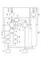
- FIG. 2 is a block diagram illustrating the container alignment apparatus according to the first embodiment.
- FIG. 3A and FIG. 3B are conceptual diagrams for explaining the operation of the container alignment apparatus of the first embodiment.
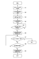
- FIG. 4 is an example of a flowchart for explaining the operation of the container alignment apparatus of the first embodiment.
- FIG. 5 is a block diagram illustrating a container alignment apparatus according to the second embodiment.
- FIG. 6 is a conceptual diagram for explaining the operation of the container alignment apparatus of the second embodiment.
- FIG. 7 is a block diagram illustrating a container alignment apparatus according to the third embodiment.
- FIG. 8 is a conceptual diagram for explaining the operation of the container alignment apparatus of the third embodiment.
- FIG. 1 is a schematic view illustrating a container crane.
- FIG. 2 is a block diagram illustrating a container alignment apparatus according to this embodiment.
- the container crane 1 has a trolley 5 that traverses along a girder 3 provided below the boom 2.
- the trolley 5 suspends the spreader 7 via a rope 6 and a head block 9.
- the container 8 is suspended via the spreader 7.
- the direction in which the trolley 5 traverses is the X-axis direction.
- the trolley 5 is supported on the ground (plane) by the support body of the container crane 1 (not shown) together with the boom 2.
- the support body of the container crane 1 can travel on a rail provided along the Y-axis direction orthogonal to the X-axis.
- the container crane 1 is installed on a plane including the X axis and the Y axis, and the container 8 is suspended along the Z axis direction orthogonal to the X axis and the Y axis.
- the direction of the Y axis is a direction along the quay and the direction of the X axis is a direction in which the boom 2 extends.
- the container crane 1 is not limited to a gantry crane, and may be a small cargo crane or another container crane.
- the container (own container) 8 suspended by the spreader 7 is stacked on other containers (target containers) 12 and 16.
- the target containers 12 and 16 are arranged in this order with the short sides along the X axis.
- the own container 8 is stacked on the desired target container 12 of the target containers 12 and 16.
- the distance sensor 20 is provided on the boom 2 or the girder 3, for example.
- the distance sensor 20 is installed at a position obliquely above the containers 8, 12, 16 so that the positions of the containers 8, 12, 16 can be measured.
- the distance sensor 20 may be provided at other positions as long as the positions of the own container 8 and the target containers 12 and 16 can be measured.
- the distance sensor 20 may be provided at the tip of the boom 2 or the like.
- the position of the lower end of the suspended container 8 is detected by the distance sensor 20.
- the position of the lower end of the container 8 can be set arbitrarily, in the following example, the coordinates of the four corners of the rectangle that constitutes the lower surface of the own container 8 are used.
- the distance sensor 20 detects the position where the container 8 is stacked. When stacking on top of the target container 12, the position of the upper end of the target container 12 is detected. Although the position of the upper end of the target container 12 can be set arbitrarily, in the following example, the position of the upper end of the target container 12 is the coordinates of four corners of a rectangle that constitutes the upper surface of the target container 12.
- the container alignment apparatus when there are a plurality of containers to be stacked, the positions of the upper ends of all the target containers 12 and 16 are detected.
- the detected position of the own container 8 and the positions of the target containers 12 and 16 are stored by the container alignment device 30.
- the position of the own container 8 is the coordinates of the four corners of the lower surface
- the positions of the target containers 12 and 16 are the coordinates of the four corners of the upper surface.
- the distance sensor 20 is, for example, a laser distance meter.
- the laser distance meter scans the laser beam in the X-axis direction and the Y-axis direction toward the object, and measures the distance to the object based on the time for receiving the reflected light and the phase of the reflected light.
- the container alignment device generates automatic operation areas 10a to 10d based on the position of the container 8 to be stacked.
- the automatic operation areas 10a to 10d are set as areas within a spherical surface having a radius R with the corner coordinates of the lower surface of the own container 8 as the center.
- the container alignment device generates the automatic operation areas 14a to 14d and 18a to 18d based on the positions of the target containers 12 and 16.
- the automatic operation areas 14a to 14d and 18a to 18d are set as areas within a hemispherical surface having a radius r that is in contact with the adjacent sides orthogonal to the rectangle on the top surface of the containers 12 and 16.
- Automatic operation is started when the automatic operation areas 10a to 10d of the own container 8 overlap with the automatic operation areas 14a to 14d of the target container 12, respectively, or overlap with the automatic operation areas 18a to 18d of the target container 16, respectively. To do.
- the container alignment device matches the position of the own container 8 with the position of the target container 12.
- the drive device is controlled as described above.
- the drive device includes, for example, an electric motor.
- the electric motor controls the winding and rewinding of the rope 6 to drive the own container 8 in the Z-axis direction.
- the electric motor converts the rotational movement into a horizontal movement by means of a drum and a rope, and controls the traversing of the trolley 5.
- the container alignment device matches the position of the own container 8 with the position of the target container 16.
- the drive device is controlled as described above.
- the drive device moves the own container 8 in the X-axis direction and the Z-axis direction in accordance with the output of the container alignment device.
- the container alignment device can smoothly perform manual operation using a manual controller at hand of the operator even when automatic operation is being performed.
- the operator When the operator operates the lever of the manual controller at a speed faster than a predetermined speed, the operator can stop the automatic operation and align the own container 8 by the manual operation.
- the operating direction of the lever at this time can be a case opposite to the direction moving by automatic driving.
- the alignment device 30 is connected to the distance sensor 20 and the manual controller 22.
- the output of the alignment device 30 is connected to the electric motor drive device 50.
- the electric motor drive device 50 is connected to the electric motor 60, and the electric motor 60 rotates according to the drive output output by the electric motor drive device 50.
- the alignment device 30 generates a speed reference signal for setting the rotation speed and the rotation direction of the electric motor 60 based on the outputs of the distance sensor 20 and the manual controller 22 and supplies the speed reference signal to the electric motor drive device 50.
- the alignment device 30 includes a control circuit 30a for the X axis and a control circuit 30b for the Z axis.
- the control circuit 30a controls the operation of the trolley 5 traversing.
- the control circuit 30b controls winding and unwinding of the rope 6.
- the control circuits 30a and 30b have the same configuration. Hereinafter, the configuration of the control circuit 30a will be described.
- the alignment device 30 of the present embodiment alignment of the traversing position (X-axis direction) of the trolley 5 and the hanging height (Z-axis direction) of the container is performed.
- the container is not aligned for movement on the rail (direction along the Y axis) by the traveling device or the like.
- the alignment device can align the container in the three directions of XYZ.
- the manual controller 22 has, for example, a lever corresponding to the X-axis direction and a lever corresponding to the Z-axis direction.
- the manual controller 22 generates and outputs an electrical signal corresponding to the direction and speed of traversing the trolley 5 by operating a lever corresponding to the X-axis direction.
- the manual controller 22 generates and outputs an electrical signal corresponding to the winding direction and speed of the rope 6 by operating a lever corresponding to the Z-axis direction.
- the control circuit 30a includes a position measurement unit 31 for the own container, a calculation unit 32 for the automatic operation region of the own container, a position measurement unit 33 for the target position, and a calculation unit 34 for the automatic operation region of the target position.
- a determination unit 35 for starting automatic driving, a calculation unit 36 for generating an automatic driving speed reference signal, a calculating unit 37 for generating a manual driving speed reference signal, and an adder 39 are included.
- the position measuring unit 31 is connected to the output of the distance sensor 20.
- the position measuring unit 31 measures the position of the container 8 based on the output of the distance sensor 20.
- the position of the own container 8 is the coordinates of the four corners of the lower surface of the own container 8.
- the position measuring unit 31 stores the measured position of the container 8 as an initial position.
- the calculation unit 32 for the automatic operation area is connected to the output of the position measurement unit 31.
- the computing unit 32 generates the automatic operation areas 10a to 10d based on the position of the own container 8.
- the automatic operation areas 10a to 10d are respectively generated corresponding to the four corners of the lower surface of the own container 8.
- the automatic driving regions 10a to 10d are generated with a spherical surface centered on each coordinate of four corners as a boundary.
- the automatic operation areas 10a to 10d are set inside these spherical surfaces.
- the radius of each spherical surface is R. In the automatic operation areas 10a to 10d, spherical surfaces having the same radius may be used as described above, or spherical surfaces having different radii for some or all of the four coordinates.
- the position measuring unit 33 is connected to the output of the distance sensor 20.
- the position measurement unit 33 measures the position of the target container 12 based on the output of the distance sensor 20.
- the position measuring unit 33 measures the positions of all the target containers 12 and 16.
- the alignment device 30 first brings the own container 8 closer to the target container by manual operation.
- the alignment device 30 automatically selects one target container from the plurality of target containers 12 and 16, and the position of the own container 8 matches the position of the selected target container.
- the predetermined condition is when the areas of the automatic operation areas 10a to 10d of the own container 8 overlap the automatic operation areas of the target container.
- the calculation unit 34 is connected to the output of the position measurement unit 33.
- the calculation unit 34 generates the automatic operation areas 14a to 14d based on the target position.
- the automatic operation areas 14a to 14d are generated corresponding to the four corners of the upper surface of the target container 12.
- the automatic operation regions 14a to 14d are formed with a hemispherical surface in contact with adjacent edges forming each of the four corners as a boundary.
- the automatic operation areas 14a to 14d are set inside these hemispherical surfaces.
- the radius of the hemisphere is all r.
- the automatic operation regions 18 a to 18 d are formed corresponding to the four corners of the upper surface of the other target container 16. Since a plurality of target containers are arranged with almost no gap, the automatic operation area is formed so that the automatic operation areas of adjacent containers do not overlap.
- the automatic operation area generated by the calculation units 32 and 34 is not limited to the spherical surface or hemispherical surface described above, but may be a cube, a rectangular parallelepiped, a cylinder, or the like.
- the automatic driving area is not limited to being formed at each of the four corners, and for example, two automatic driving areas may be formed with one container so as to include adjacent corners.
- the determination unit 35 detects whether or not the four automatic operation areas of the own container 8 and the target containers 12 and 16 overlap each other. In this example, the determination unit 35 detects the traversing distance of the trolley 5 based on the rotational speed of the electric motor 60 detected by the resolver 62 attached to the electric motor 60. The alignment device 30 is based on the traverse distance of the trolley 5, the initial position of the own container 8, and the position of the target container. The automatic operation areas 10a to 10d of the own container 8 and the automatic operation areas 14a to 14d, 18a to 18d is calculated. The determination unit 35 determines whether or not the automatic operation areas 10a to 10d overlap any of the automatic operation areas 14a to 14d or the automatic operation areas 18a to 18d.
- the determination unit 35 selects the target container 12 as a target position when all of the automatic driving areas 10a to 10d overlap the automatic driving areas 14a to 14d, respectively.
- the determination unit 35 selects the target container 16 as the target position when all of the automatic driving areas 10a to 10d overlap the automatic driving areas 18a to 18d, respectively.
- the calculation unit 36 that generates the automatic driving speed reference generates the speed reference signal Va0 so that the position of the own container 8 matches the position of the selected target container.
- the calculation unit 36 may multiply the generated speed reference signal Va0 by a predetermined coefficient ⁇ to obtain the speed reference signal Va1.
- Va1 is used as a speed reference signal corresponding to automatic driving unless otherwise specified.
- the calculation unit 37 that generates the manual operation speed reference is connected to the output of the manual controller 22.
- the computing unit 37 generates the speed reference signal Vm0 based on the speed in the X-axis direction output from the manual controller 22 and the manual control signal indicating the direction.
- the speed reference signal corresponding to the manual operation is preferably generated by the distance calculation unit 38 so as to be inversely proportional to the distance LX between the position of the own container 8 and the position of the target container.
- the distance calculation unit 38 is connected to the outputs of the determination unit 35 and the calculation unit 37 in this example.
- the distance calculation unit 38 sets the ratio of manual operation according to the distance LX between the position of the own container 8 and the target position output from the determination unit 35.
- Vm1 ⁇ ⁇ Vm0 / LX (1)
- ⁇ is a constant.
- the speed reference signal Va1 is added to the speed reference signal Vm1 and supplied to the motor drive device 50.
- the electric motor drive device 50 generates a drive signal according to the speed reference signal (Va1 + Vm1), and drives the electric motor 60.
- Arbitrary constants ⁇ and ⁇ are set in advance. By setting these to appropriate values, the behavior of the alignment device 30 can be made smoother when manual operation is performed during automatic operation or when automatic operation is activated during manual operation. .
- the acceleration detection unit 40 is connected to the output of the calculation unit 37.
- the acceleration detection unit 40 outputs a disable signal when the speed change in manual driving, that is, when the acceleration is larger than a predetermined value.
- the disable signal is input to the calculation unit 36.
- the arithmetic unit 36 stops its operation when the disable signal is input.
- the case where the acceleration is larger than a predetermined value means a case where the manual controller 22 is operated rapidly, and is operated when the operator wants to forcibly stop the automatic operation after the automatic operation starts.
- the alignment device 30 can perform smooth container alignment by using both automatic operation and manual operation.
- FIG. 3A and FIG. 3B are conceptual diagrams for explaining the operation of the alignment apparatus of the present embodiment.
- FIG. 4 is a flowchart for explaining the operation of the container alignment apparatus of the present embodiment.
- FIG. 3A and FIG. 3B are represented as plan views of the own container 8 and the target containers 12 and 16 as viewed from above.
- the own container 8 is located approximately in the middle between the two target containers 12 and 16.
- the automatic operation areas 10 c and 10 d of the own container 8 overlap with the automatic operation areas 14 a to 14 d of one target container 12.
- the automatic operation areas 10 a and 10 b of the own container 8 overlap with the automatic operation areas 16 a to 16 d of the other target container 16. That is, the automatic operation region 10a ⁇ 10d of the own container 8 does not overlap each automatic operation region of one of the target container. In such a case, the automatic operation of the alignment device 30 is not started, and the operator uses the manual controller 22 to move the own container 8 toward one target container 12 or the other target container 16.
- the automatic operation areas 10c and 10d of the own container 8 overlap with the automatic operation areas 14a and 14b of one target container 12.
- the automatic operation areas 10a to 10d of the own container 8 overlap with all the automatic operation areas 18a to 18d of the other target container 16, respectively.
- the alignment device 30 selects the other target container 16 as a target for automatic operation, and starts automatic operation.
- step S ⁇ b> 1 the position measuring unit 31 measures the position of the container 8 based on the output of the distance sensor 20.
- the position measuring unit 31 stores the measured position of the container 8 as an initial position.
- step S2 the calculation unit 32 generates the automatic operation areas 10a to 10d based on the initial position of the own container 8.
- the calculation unit 32 stores the generated automatic operation areas 10a to 10d.
- step S3 the position measuring unit 33 measures the positions of the target containers 12 and 16 based on the output of the distance sensor 20.
- the position measuring unit 33 stores the measured positions of the target containers 12 and 16.
- step S4 the calculation unit 34 generates the automatic operation areas 14a to 14d and 18a to 18d based on the positions of the target containers 12 and 16, respectively.
- the calculation unit 34 stores the generated automatic operation areas 14a to 14d and 18a to 18d.
- step S5 the determination unit 35 determines whether or not the automatic operation areas 10a to 10d overlap the automatic operation areas of any of the target containers 12 and 16, respectively.
- the determination unit 35 transitions to the next step S6 if they overlap, and waits until an overlap is detected if they do not overlap.
- step S6 the determination unit 35 transmits the data of the position of the container 8 and the target position to the calculation unit 36, and activates the calculation unit 36.
- the calculation unit 36 generates a speed reference signal so that the position of the container 8 matches the target position.
- the speed reference signal Va1 for automatic operation is added to the speed reference signal Vm1 for manual operation.
- the added speed reference signal is supplied to the motor drive device 50.
- the computing unit 37 outputs the speed reference signal Vm0 for manual operation according to the signal input from the manual controller 22. At this time, the speed reference signal Vm0 is equal to Vm1.
- step S7 the calculation unit 36 and the calculation unit 37 determine whether the position of the own container 8 matches the target position based on the calculation result and the output of the resolver 62. If the position of the own container 8 matches the target position, the process is terminated. If the position of the own container 8 does not match the target position, the process proceeds to the next step S8.
- step S8 the calculation unit 36 determines whether a disable signal from the acceleration detection unit 40 is detected. When detecting the disable signal, the calculation unit 36 stops the operation in step S9. If the calculation unit 36 does not detect the disable signal, the calculation unit 36 returns to the process of step S7.
- the alignment device 30 aligns the container by manual operation by the manual controller 22.
- the alignment device 30 described above loads a program and operates according to each step of the program, such as a CPU (Central Processing Unit) or an MPU (Micro-Processing Unit), and a storage unit such as a memory element that stores the program. , May be configured. In that case, a part or all of each part of the control circuits 30a and 30b of the alignment apparatus 30 is executed as a part or all of the program.
- a CPU Central Processing Unit
- MPU Micro-Processing Unit
- the alignment device 30 may be realized by a PLC (Programmable Logic Controller).
- the PLC executes part or all of the control circuits 30a and 30b as part or all of a ladder program stored in a storage device such as a memory.
- the calculation unit 36 generates the speed reference signal Va1 for automatic operation, and simultaneously generates the speed reference signals Vm0 and Vm1 for manual operation, and based on these, the motor drive device A speed reference signal for 50 is generated.
- the alignment device 30 generates an automatic operation region based on the position of the container 8 and the target position by the calculation units 32 and 34. Automatic operation is started when the automatic operation areas of the own container 8 and the target container overlap each other. Therefore, manual operation and automatic operation can be operated in cooperation. When the automatic operation is started, the own container 8 can be moved so as to be drawn to the target position, and the automatic operation can be smoothly performed in the manual operation.
- FIG. 5 is a block diagram illustrating the alignment apparatus according to this embodiment.
- the alignment device when the own container 8 is too close to the target container 12 in the alignment in the Z-axis direction, the alignment device operates to move the own container 8 away from the target container 12. Thereby, the alignment apparatus can prevent the own container 8 from colliding with the side surface of the container 12 at the target position.
- the alignment device 130 of this embodiment includes a control circuit 130b in the Z-axis direction.
- the control circuit 30a in the X-axis direction is the same as that in the first embodiment.
- the control circuit 130b includes a position measurement unit 31 for the own container, a calculation unit 32 for the automatic operation region of the own container, a position measurement unit 33 for measuring the automatic target position, and a calculation for the automatic operation region of the target position.
- Unit 34 a determination unit 135 for starting automatic driving, a calculation unit 136 for generating a speed reference signal for automatic driving, a calculation unit 37 for generating a speed reference signal for manual driving, and an adder 39.
- the determination unit 135 and the calculation unit 136 are different from those in the first embodiment.
- symbol is attached
- the determination unit 135 for starting the automatic operation determines whether any of the automatic operation regions 10a to 10d of the own container 8 overlaps any of the automatic operation regions 14a to 14d at the target position. When any of the automatic operation areas 10a to 10d of the own container 8 overlaps with any of the automatic operation areas 14a to 14d of the target position, the determination unit 135 provides data on the position of the own container 8 and the target position. Is supplied to the calculation unit 136.
- the calculation unit 136 that generates a speed reference for automatic driving is activated by receiving data on the position of the container 8 and the target position from the determination unit 35.
- the calculation unit 136 generates a speed reference signal VZa that is inversely proportional to the distance LZ between the position of the container 8 and the target position and that has a direction in which the distance is separated.
- the direction in which the own container 8 is separated from the target position is the positive direction of the Z axis when the automatic operation is started when the own container 8 is moved in the negative direction of the Z axis by manual operation. This means that the speed reference signal VZa toward is generated.
- FIG. 6 is a conceptual diagram for explaining the operation of the alignment apparatus of the present embodiment.
- the own container 8 is located above and to the side of the target container 12.
- the automatic operation areas 10 a and 10 b of the own container 8 overlap with the automatic operation areas 14 c and 14 d of the target container 12.
- the calculation unit 136 is activated and the automatic operation of the alignment device 130 starts operating.
- the speed reference signal VZa generated by the calculation unit 136 is generated in the direction of the upward arrow in FIG.
- the magnitude of the speed reference signal VZa is generated so as to be inversely proportional to the distance LZ between the position of the container 8 on the Z axis and the position of the target container 12 on the Z axis.
- the self-container 8 is driven in a direction opposite to the direction approached by the large speed reference signal VZa as it approaches the target container 12. Therefore, in the automatic operation, the own container 8 operates so as to be repelled from the target container 12 when approaching the target container 12.
- the speed reference signal VZa is positively generated so as to move the own container 8 away from the target container 12. Therefore, it is possible to prevent the own container 8 from colliding with the side surface of the target container 12.
- both the control circuit 130b of the present embodiment and the control circuit 30b of the first embodiment are mounted on the alignment apparatus, and are used by appropriately switching them with a switch or the like at the operator's hand. It can also be.
- FIG. 7 is a block diagram illustrating the alignment apparatus of this embodiment.
- FIG. 8 is a conceptual diagram for explaining the operation of the alignment apparatus of the present embodiment.
- the own container 8 can be aligned to the target position more smoothly by changing the shape of the automatic operation area of the target position.
- the alignment device 230 includes a control circuit 230b.
- the control circuit 230b operates for movement in the Z-axis direction.
- the control circuit 230b includes a calculation unit 234 instead of the calculation unit 34 for the automatic operation region in the case of the second embodiment described above.
- symbol is attached
- the calculation unit 234 for the automatic driving region generates an automatic driving region different from the calculation unit 34 in the case of the other embodiments described above at the target position.
- the automatic operation regions 214a to 214d of the target container 12 are formed from the outer periphery of the upper surface of the target container 12 to the outside. Further, the boundaries of the automatic operation regions 214 a to 214 d are formed so as to extend upward from the upper surface of the target container 12. In this example, a boundary is formed so as to be 45 ° upward from the upper surface of the target container 12.
- the calculation unit 136 of the control circuit 230b in charge of the Z-axis After being activated, the calculation unit 136 of the control circuit 230b in charge of the Z-axis generates a speed reference signal in the direction of separation with a magnitude inversely proportional to the distance between the position of the own container 8 and the position of the target container 12. To do.
- the calculation unit 136 generates the speed reference signal as described above, and the calculation unit 36 of the control circuit 30a responsible for the movement of the X axis generates the speed reference signal so that the position of the container 8 and the target position are attracted to each other. To do. Therefore, the own container 8 is aligned so as to gradually approach the target position.
- control circuit 230b of this embodiment is appropriately switched from the control circuit 30b of the first embodiment and the control circuit 130b of the second embodiment by a switch or the like at the operator's hand. You may make it use.
- an alignment device capable of smoothly aligning a container by using both manual operation and automatic operation.
Landscapes
- Engineering & Computer Science (AREA)
- Mechanical Engineering (AREA)
- Automation & Control Theory (AREA)
- Aviation & Aerospace Engineering (AREA)
- Physics & Mathematics (AREA)
- General Physics & Mathematics (AREA)
- Control And Safety Of Cranes (AREA)
Abstract
手動運転および自動運転を併用して、コンテナの位置合わせをすることができるコンテナの位置合わせ装置が提供される。位置合わせ装置は、位置センサの検出結果にもとづいて前記コンテナの位置を測定する演算を実行する第1演算部と、前記位置センサの検出結果にもとづいて前記コンテナを載置する目標位置を測定する演算を実行する第2演算部と、前記コンテナの位置にもとづいて前記自動運転を行う第1自動運転領域および前記目標位置にもとづいて前記自動運転を行う第2自動運転領域をそれぞれ計算して設定する第3演算部と、前記第1自動運転領域が前記第2自動運転領域に重なったことを検出し、前記コンテナの位置を前記目標位置に一致させるように第1速度基準信号を生成する第1信号生成部と、オペレータの操作によって生成された手動制御信号にもとづいて前記コンテナを移動させるための第2速度基準信号を生成する第2信号生成部と、を備える。
Description
本発明の実施形態は、コンテナの位置合わせ装置に関する。
従来のコンテナ積み上げの位置合わせでは、オペレータは、トロリーにある運転室から目視によって、積み上げられているコンテナの高さ、位置を把握する。オペレータは、ロープの巻き操作によって、積み上げを行うコンテナを掴んでいるスプレッダの高さを調節し、トロリーを横行させて、目標のコンテナの上部まで移動させてコンテナを積み上げる。
オペレータは、目視以外に、カメラからの映像により遠隔の操作室からロープの巻き操作や、トロリーの横行操作を行い、コンテナ上への積み上げ、あるいはトラックシャーシへの積み下ろしを行う場合もある。
ところが、遠隔操作の場合には、カメラの台数が限られており、カメラの設置位置や角度によっては、目標のコンテナの位置が見えにくかったり、遠近感が判りにくかったりなどすることがある。そのため、遠隔操作による積み上げ操作では、運転室からの目視による積み上げ操作よりも作業時間がかかることがある。
特許文献1には、レーザー距離計によって、コンテナの位置とスプレッダの位置とを精度よく測定する方法が開示されている。しかし、コンテナのような重量物の積み上げ作業では、安全面の配慮からオペレータの目視によって行われることが求められている。
コンテナの位置合わせの自動化に関する技術では、手動運転と自動運転とを明確に切り分けている。たとえば、自動運転によって位置合わせを行っているときに手動運転を行おうとすると、自動運転が停止し、手動運転に切替わるように設定されている。この方法では、自動運転をしながら、手動運転によって、コンテナの位置を微調整をすることが難しい。また、手動運転を行う際、自動運転がすべて停止するので、切り替わりがスムーズでなく、オペレータがストレスを感じることがある。手動運転中に自動運転を起動させる場合にも、オペレータの操作の邪魔をするようなぎくしゃくした動きになる。
実施形態は、手動運転および自動運転を併用して、スムーズにコンテナの位置合わせをすることができるコンテナの位置合わせ装置を提供する。
本発明の実施形態によれば、コンテナの位置合わせ装置は、オペレータによる手動運転およびオペレータを介さない自動運転を併用してコンテナの位置合わせをする。コンテナの位置合わせ装置は、位置センサの検出結果にもとづいて前記コンテナの位置を測定する演算を実行する第1演算部と、前記位置センサの検出結果にもとづいて前記コンテナを載置する目標位置を測定する演算を実行する第2演算部と、前記コンテナの位置にもとづいて前記自動運転を行う第1自動運転領域および前記目標位置にもとづいて前記自動運転を行う第2自動運転領域をそれぞれ計算して設定する第3演算部と、前記第1自動運転領域が前記第2自動運転領域に重なったことを検出し、前記コンテナの位置を前記目標位置に一致させるように第1速度基準信号を生成する第1信号生成部と、オペレータの操作によって生成された手動制御信号にもとづいて前記コンテナを移動させるための第2速度基準信号を生成する第2信号生成部と、を備える。位置合わせ装置は、前記第1信号生成部および前記第2信号生成部の出力にもとづいて第3速度基準信号を生成し、前記コンテナを移動させる駆動装置に前記第3速度基準信号を供給する。
本発明の実施形態によれば、コンテナの位置合わせ装置は、第1信号生成部と、第2信号生成部と、を備え、前記第1信号生成部および前記第2信号生成部の出力にもとづいて、前記コンテナを移動させる駆動装置に第3速度基準信号を供給するので、手動運転および自動運転を併用して、コンテナの位置合わせをスムーズに行うことができる。
以下に、各実施の形態について図面を参照しつつ説明する。
なお、図面は模式的または概念的なものであり、各部分の厚みと幅との関係、部分間の大きさの比率などは、必ずしも現実のものと同一とは限らない。また、同じ部分を表す場合であっても、図面により互いの寸法や比率が異なって表される場合もある。
なお、本願明細書と各図において、既出の図に関して前述したものと同様の要素には同一の符号を付して詳細な説明は適宜省略する。
なお、図面は模式的または概念的なものであり、各部分の厚みと幅との関係、部分間の大きさの比率などは、必ずしも現実のものと同一とは限らない。また、同じ部分を表す場合であっても、図面により互いの寸法や比率が異なって表される場合もある。
なお、本願明細書と各図において、既出の図に関して前述したものと同様の要素には同一の符号を付して詳細な説明は適宜省略する。
(第1の実施形態)
図1は、コンテナクレーンを例示する模式図である。
図2は、本実施形態に係るコンテナの位置合わせ装置を例示するブロック図である。
図1に示すように、コンテナクレーン1は、ブーム2の下側に設けられたガーダー3に沿って横行するトロリー5を有している。トロリー5は、ロープ6およびヘッドブロック9を介してスプレッダ7を吊り下げている。コンテナ8は、スプレッダ7を介して吊り下げられている。
図1は、コンテナクレーンを例示する模式図である。
図2は、本実施形態に係るコンテナの位置合わせ装置を例示するブロック図である。
図1に示すように、コンテナクレーン1は、ブーム2の下側に設けられたガーダー3に沿って横行するトロリー5を有している。トロリー5は、ロープ6およびヘッドブロック9を介してスプレッダ7を吊り下げている。コンテナ8は、スプレッダ7を介して吊り下げられている。
以下の説明では、トロリー5が横行する方向をX軸方向とする。トロリー5は、ブーム2とともに、図示しないコンテナクレーン1の支持体によって地面(平面)に支持されている。コンテナクレーン1の支持体は、X軸に直交するY軸方向に沿って設けられたレール上を走行することができる。コンテナクレーン1は、X軸およびY軸を含む平面に設置されており、コンテナ8は、X軸およびY軸に直交するZ軸方向に沿って吊り下げられているものとする。
コンテナクレーン1が、港湾における荷役に用いられる大型クレーンであるガントリークレーン等の場合には、Y軸の方向は、岸壁に沿う方向であり、X軸の方向は、ブーム2が延伸する方向である。なお、コンテナクレーン1は、ガントリークレーンに限らず、小型の荷役用クレーンであってもよく、他のコンテナクレーンであってもよい。
スプレッダ7によって吊り下げられたコンテナ(自コンテナ)8は、他のコンテナ(目標コンテナ)12,16上に積み上げられる。目標コンテナ12,16は、短辺がX軸に沿うようにして、この順で並べられている。トロリー5がX軸に沿って横行することによって、自コンテナ8は、目標コンテナ12,16のうちの所望の目標コンテナ12上に積み上げられる。
距離センサ20は、たとえばブーム2やガーダー3に設けられている。距離センサ20は、コンテナ8,12,16の位置を測定することができるように、コンテナ8,12,16に対して斜め上方の位置に設置されている。距離センサ20は、自コンテナ8および目標コンテナ12,16の位置を測定することができれば、他の位置に設けられていてもよい。たとえば、距離センサ20は、ブーム2の先端等に設けられていてもよい。本実施形態のコンテナの位置合わせ装置では、距離センサ20によって、吊り下げている自コンテナ8の下端の位置を検出する。コンテナ8の下端の位置は、任意に設定することができるが、以下の例では、自コンテナ8の下面を構成する長方形の4つの角の座標である。
距離センサ20は、自コンテナ8を積み上げる位置を検出する。目標コンテナ12の上部に積み上げる場合には、目標コンテナ12の上端の位置を検出する。目標コンテナ12の上端の位置は、任意に設定することができるが、以下の例では、目標コンテナ12の上端の位置は、目標コンテナ12の上面を構成する長方形の4つの角の座標である。
コンテナの位置合わせ装置では、積み上げの目標となるコンテナが複数ある場合には、すべての目標コンテナ12,16の上端の位置が検出される。
検出された自コンテナ8の位置および目標コンテナ12,16の位置は、コンテナの位置合わせ装置30によって記憶される。以下では、自コンテナ8の位置は、下面の4つの角の座標であり、目標コンテナ12,16の位置は、上面の4つの角の座標であるものとする。
距離センサ20は、たとえばレーザー距離計である。レーザー距離計は、対象物に向けてX軸方向およびY軸方向にレーザー光を走査して、反射光を受光する時間および反射光の位相等によって対象物までの距離を計測する。
コンテナの位置合わせ装置は、積み上げる自コンテナ8の位置にもとづいて、自動運転領域10a~10dを生成する。この例では、自動運転領域10a~10dは、自コンテナ8の下面の角の座標を中心とする半径Rの球面内の領域として設定される。
コンテナの位置合わせ装置は、目標コンテナ12,16の位置にもとづいて、自動運転領域14a~14d,18a~18dを生成する。この例では、自動運転領域14a~14d,18a~18dは、コンテナ12,16の上面の長方形に直交して隣接する辺に接する半径rの半球面内の領域として設定される。
自コンテナ8の自動運転領域10a~10dが、目標コンテナ12の自動運転領域14a~14dにそれぞれ重なった場合、または目標コンテナ16の自動運転領域18a~18dにそれぞれ重なった場合に、自動運転は起動する。
自コンテナ8の自動運転領域10a~10dが、目標コンテナ12の自動運転領域14a~14dにそれぞれ重なった場合には、コンテナの位置合わせ装置は、自コンテナ8の位置が目標コンテナ12の位置に一致するように、駆動装置を制御する。駆動装置は、たとえば電動機を含んでいる。電動機は、ロープ6の巻き取りや巻き戻しを制御して自コンテナ8をZ軸方向に駆動する。電動機は、ドラムおよびロープ等によって回転運動を水平方向の運動に変換して、トロリー5の横行を制御する。
自コンテナ8の自動運転領域10a~10dが、目標コンテナ16の自動運転領域18a~18dにそれぞれ重なった場合には、コンテナの位置合わせ装置は、自コンテナ8の位置が目標コンテナ16の位置に一致するように、駆動装置を制御する。駆動装置は、コンテナの位置合わせ装置の出力にしたがって、自コンテナ8をX軸方向およびZ軸方向に移動させる。
コンテナの位置合わせ装置は、自動運転を実行しているときにも、オペレータの手元にある手動コントローラを用いて手動運転をスムーズに実行することができる。
オペレータは、手動コントローラのレバーを所定よりも早い速度で操作したときには、自動運転を停止させ、手動運転で自コンテナ8の位置合わせを行うことができる。このときのレバーの操作方向は、自動運転によって移動している方向とは逆方向の場合とすることができる。
図1および図2を参照して、コンテナの位置合わせ装置(以下、単に位置合わせ装置ともいう。)30の構成について説明する。
図2に示すように、位置合わせ装置30は、距離センサ20および手動コントローラ22にそれぞれ接続されている。位置合わせ装置30の出力は、電動機駆動装置50に接続されている。電動機駆動装置50は、電動機60に接続され、電動機60は、電動機駆動装置50が出力する駆動出力にしたがって回転する。位置合わせ装置30は、距離センサ20および手動コントローラ22の出力にもとづいて、電動機60の回転速度および回転方向を設定する速度基準信号を生成して電動機駆動装置50に供給する。
図2に示すように、位置合わせ装置30は、距離センサ20および手動コントローラ22にそれぞれ接続されている。位置合わせ装置30の出力は、電動機駆動装置50に接続されている。電動機駆動装置50は、電動機60に接続され、電動機60は、電動機駆動装置50が出力する駆動出力にしたがって回転する。位置合わせ装置30は、距離センサ20および手動コントローラ22の出力にもとづいて、電動機60の回転速度および回転方向を設定する速度基準信号を生成して電動機駆動装置50に供給する。
位置合わせ装置30は、X軸に対する制御回路30aと、Z軸に対する制御回路30bと、を備える。制御回路30aは、トロリー5が横行する動作を制御する。制御回路30bは、ロープ6の巻き取りおよび巻き戻しを制御する。本実施形態の場合は、制御回路30a,30bは、同一の構成を有している。以下では、制御回路30aの構成について説明する。
本実施形態の位置合わせ装置30では、トロリー5の横行位置(X軸の方向)およびコンテナの吊り下げ高さ(Z軸の方向)の位置合わせを行うものとする。以下説明する本実施形態では、走行装置等によるレール上の移動(Y軸に沿う方向)については、コンテナの位置合わせを行わないものとする。Y軸についても制御回路30a,30bと同様の制御回路を用意することによって、位置合わせ装置は、XYZの3方向についてコンテナの位置合わせを行うことができる。
手動コントローラ22は、図示しないが、たとえばX軸方向に対応するレバーと、Z軸方向に対応するレバーと、を有している。手動コントローラ22は、X軸方向に対応するレバーを操作することによって、トロリー5を横行させる向きおよび速度に対応した電気信号を生成して出力する。手動コントローラ22は、Z軸方向に対応するレバーを操作することによって、ロープ6の巻きの向きおよび速度に対応した電気信号を生成して出力する。
制御回路30aは、自コンテナの位置測定部31と、自コンテナの自動運転領域のための演算部32と、目標位置の位置測定部33と、目標位置の自動運転領域のための演算部34と、自動運転開始のための判定部35と、自動運転速度基準信号を生成する演算部36と、手動運転速度基準信号を生成する演算部37と、加算器39と、を含む。
位置測定部31は、距離センサ20の出力に接続されている。位置測定部31は、距離センサ20の出力にもとづいて、自コンテナ8の位置を測定する。自コンテナ8の位置は、この例では、自コンテナ8の下面の4つの角の座標である。位置測定部31は、測定された自コンテナ8の位置を初期位置として記憶する。
自動運転領域のための演算部32は、位置測定部31の出力に接続されている。演算部32は、自コンテナ8の位置にもとづいて、自動運転領域10a~10dを生成する。自動運転領域10a~10dは、自コンテナ8の下面の4つの角に対応してそれぞれ生成される。自動運転領域10a~10dは、4つの角の各座標を中心とする球面を境界として生成される。自動運転領域10a~10dは、これらの球面の内側に設定される。球面の半径は、いずれもRである。自動運転領域10a~10dでは、このように同一半径の球面としてもよく、4つの座標の一部または全部に対して異なる半径の球面としてもよい。
位置測定部33は、距離センサ20の出力に接続されている。位置測定部33は、距離センサ20の出力にもとづいて、目標コンテナ12の位置を測定する。複数の目標コンテナがX軸方向に沿って並べられている場合には、位置測定部33は、すべての目標コンテナ12,16の位置を測定する。詳細については後述するが、位置合わせ装置30では、最初に手動運転によって、自コンテナ8を目標コンテナに近づけていく。所定の条件を満たした場合に、位置合わせ装置30は、複数の目標コンテナ12,16から1つの目標コンテナを自動的に選択し、自コンテナ8の位置と、選択した目標コンテナの位置とが一致するように動作する。所定の条件は、自コンテナ8の自動運転領域10a~10dの領域が、目標コンテナの自動運転領域にそれぞれ重なった場合である。
演算部34は、位置測定部33の出力に接続されている。演算部34は、目標位置にもとづいて、自動運転領域14a~14dを生成する。自動運転領域14a~14dは、目標コンテナ12の上面の4つの角に対応して生成される。自動運転領域14a~14dは、4つの角のそれぞれを形成する隣接する稜に接する半球の面を境界として形成される。自動運転領域14a~14dは、これらの半球面の内側に設定される。半球面の半径は、いずれもrである。目標コンテナが複数ある場合には、自動運転領域18a~18dは、他の目標コンテナ16の上面の4つの角に対応して形成される。目標コンテナは、複数個がほとんど隙間なく並べられるので、自動運転領域は、隣接するコンテナの自動運転領域が重ならないように形成される。
演算部32,34によって生成される自動運転領域は、上述の球面や半球面に限らず、立方体や直方体状、円柱状等であってもよい。自動運転領域は、4つの角のそれぞれに形成される場合に限らず、たとえば、隣接する角を包含するように、1つのコンテナで2つの自動運転領域を形成する等してもよい。
判定部35は、自コンテナ8および目標コンテナ12,16のそれぞれ4つの自動運転領域が重なるか否かを検出する。判定部35は、この例では、電動機60に取り付けられたレゾルバ62によって検出された電動機60の回転数にもとづいて、トロリー5の横行する距離を検出する。位置合わせ装置30は、トロリー5の横行距離、自コンテナ8の初期位置および目標コンテナの位置にもとづいて、自コンテナ8の自動運転領域10a~10dおよび目標位置の自動運転領域14a~14d,18a~18dを計算する。判定部35は、自動運転領域10a~10dが、自動運転領域14a~14dまたは自動運転領域18a~18dのいずれかに重なったか否かを判定する。判定部35は、自動運転領域10a~10dのすべてが自動運転領域14a~14dにそれぞれ重なったときには、目標コンテナ12を目標位置として選択する。判定部35は、自動運転領域10a~10dのすべてが自動運転領域18a~18dにそれぞれ重なったときには、目標コンテナ16を目標位置として選択する。
自動運転速度基準を生成する演算部36は、自コンテナ8の位置が、選択された目標コンテナの位置に一致するように速度基準信号Va0を生成する。演算部36は、生成された速度基準信号Va0に所定の係数αを乗じて速度基準信号Va1としてもよい。以下では、特に断らない限り、自動運転に対応する速度基準信号には、Va1を用いるものとする。
手動運転速度基準を生成する演算部37は、手動コントローラ22の出力に接続されている。演算部37は、手動コントローラ22から出力されるX軸方向の速度およびその向きを表す手動制御信号にもとづいて速度基準信号Vm0を生成する。
手動運転に対応する速度基準信号は、好ましくは、距離演算部38によって、自コンテナ8の位置と目標コンテナの位置との間の距離LXに反比例するように生成される。距離演算部38は、この例では、判定部35および演算部37の出力に接続されている。距離演算部38は、判定部35から出力される自コンテナ8の位置と目標位置との距離LXによって、手動運転の割合を設定する。
Vm1=β×Vm0/LX (1)
ここで、βは、定数である。
ここで、βは、定数である。
式(1)のように手動運転時の速度基準信号Vm0を修正することによって、自コンテナ8の位置が目標位置に近づくほど、手動運転の影響を強めることができる。
速度基準信号Va1は、速度基準信号Vm1と加算されて、電動機駆動装置50に供給される。電動機駆動装置50は、速度基準信号(Va1+Vm1)にしたがって駆動信号を生成して、電動機60を駆動する。
なお、任意の定数α,βは、あらかじめ設定される。これらを適切な値に設定することによって、自動運転中に手動運転の操作を行った場合、あるいは手動運転中に自動運転が起動した場合の位置合わせ装置30の挙動をよりスムーズにすることができる。
加速度検出部40は、演算部37の出力に接続されている。加速度検出部40は、手動運転における速度変化、すなわち加速度が所定値よりも大きい場合にディスエーブル信号を出力する。ディスエーブル信号は、演算部36に入力される。演算部36は、ディスエーブル信号が入力されたときには、動作を停止する。加速度が所定値よりも大きくなる場合とは、手動コントローラ22の操作を急激に行う場合を意味しており、自動運転開始後にオペレータが自動運転を強制的に停止したいときに操作する。
このようにして、位置合わせ装置30では、自動運転および手動運転を併用して、スムーズなコンテナの位置合わせを行うことができる。
本実施形態のコンテナの位置合わせ装置30の動作について説明する。
図3(a)および図3(b)は、本実施形態の位置合わせ装置の動作を説明するための概念図である。
図4は、本実施形態のコンテナの位置合わせ装置の動作を説明するためのフローチャートである。
図3(a)および図3(b)は、本実施形態の位置合わせ装置の動作を説明するための概念図である。
図4は、本実施形態のコンテナの位置合わせ装置の動作を説明するためのフローチャートである。
図3(a)および図3(b)は、自コンテナ8および目標コンテナ12,16を上方から見た平面図として表されている。図3(a)では、自コンテナ8は、2つの目標コンテナ12,16のほぼ中間に位置している。自コンテナ8の自動運転領域10c,10dは、一方の目標コンテナ12の自動運転領域14a~14dと重なっている。自コンテナ8の自動運転領域10a,10bは、他方の目標コンテナ16の自動運転領域16a~16dと重なっている。つまり、自コンテナ8の自動運転領域10a~10dは、いずれかの目標コンテナの自動運転領域にそれぞれ重なり合っていない。このような場合には、位置合わせ装置30の自動運転は開始されず、オペレータが手動コントローラ22を用いて、自コンテナ8を一方の目標コンテナ12または他方の目標コンテナ16の方へ移動させる。
図3(b)では、自コンテナ8の自動運転領域10c,10dは、一方の目標コンテナ12の自動運転領域14a,14bと重なっている。自コンテナ8の自動運転領域10a~10dは、他方の目標コンテナ16のすべての自動運転領域18a~18dとそれぞれ重なっている。位置合わせ装置30は、他方の目標コンテナ16を自動運転の目標として選択し、自動運転を開始する。
図4のフローチャートを用いて、位置合わせ装置30の動作をより具体的に説明する。
ステップS1において、位置測定部31は、距離センサ20の出力にもとづいて、自コンテナ8の位置を測定する。位置測定部31は、測定された自コンテナ8の位置を初期位置として記憶する。
ステップS1において、位置測定部31は、距離センサ20の出力にもとづいて、自コンテナ8の位置を測定する。位置測定部31は、測定された自コンテナ8の位置を初期位置として記憶する。
ステップS2において、演算部32は、自コンテナ8の初期位置にもとづいて、自動運転領域10a~10dを生成する。演算部32は、生成された自動運転領域10a~10dを記憶する。
ステップS3において、位置測定部33は、距離センサ20の出力にもとづいて、目標コンテナ12,16の位置を測定する。位置測定部33は、測定された目標コンテナ12,16の位置を記憶する。
ステップS4において、演算部34は、目標コンテナ12,16の位置にもとづいて、自動運転領域14a~14d,18a~18dをそれぞれ生成する。演算部34は、生成された自動運転領域14a~14d,18a~18dを記憶する。
ステップS5において、判定部35は、自動運転領域10a~10dが、いずれかの目標コンテナ12,16の自動運転領域にそれぞれに重なったか否かを判定する。判定部35は、重なった場合には、次のステップS6に遷移し、重ならない場合には、重なりを検出するまで待機する。
ステップS6において、判定部35は、演算部36に、自コンテナ8の位置および目標位置のデータを送信して、演算部36を起動する。演算部36は、自コンテナ8の位置が、目標位置に一致するように速度基準信号を生成する。自動運転のための速度基準信号Va1は、手動運転のための速度基準信号Vm1と加算される。加算された速度基準信号は、電動機駆動装置50に供給される。
自動運転が起動していない場合であっても、手動コントローラ22から入力される信号にしたがって、演算部37は、手動運転のための速度基準信号Vm0を出力する。このときの速度基準信号Vm0はVm1に等しい。
ステップS7において、演算部36および演算部37は、演算結果およびレゾルバ62の出力にもとづいて、自コンテナ8の位置が、目標位置に一致したか否かを判定する。自コンテナ8の位置が、目標位置に一致した場合には、処理を終了する。自コンテナ8の位置が、目標位置に一致しない場合には、次のステップS8に処理が遷移する。
ステップS8において、演算部36は、加速度検出部40からのディスエーブル信号を検知したか否かを判定する。演算部36は、ディスエーブル信号を検知した場合には、ステップS9において、動作を停止する。演算部36は、ディスエーブル信号を検知しない場合には、ステップS7の処理に戻る。
自動運転を停止した場合には、位置合わせ装置30は、手動コントローラ22による手動運転によってコンテナの位置合わせを行う。
上述の位置合わせ装置30は、プログラムをロードして、プログラムの各ステップにしたがって動作するCPU(Central Processing Unit)やMPU(Micro-Processing Unit)等と、プログラムを格納するメモリ素子等の記憶部と、によって構成されてもよい。その場合には、位置合わせ装置30の制御回路30a,30bの各部は、その一部または全部がプログラムの一部または全部として実行される。
また、位置合わせ装置30は、PLC(Programmable Logic Controller)によって実現されてもよい。PLCは、制御回路30a,30bの一部または全部を、たとえばメモリ等の記憶装置に格納されたラダープログラムの一部または全部として実行する。
本実施形態の位置合わせ装置の効果について説明する。
本実施形態の位置合わせ装置30では、演算部36によって自動運転のための速度基準信号Va1を生成し、同時に手動運転のための速度基準信号Vm0,Vm1を生成し、これらにもとづいて電動機駆動装置50のための速度基準信号を生成する。位置合わせ装置30は、演算部32,34によって、自コンテナ8の位置および目標位置にもとづいて、自動運転領域を生成する。自コンテナ8および目標コンテナの自動運転領域がそれぞれ重なった場合に自動運転が起動される。そのため、手動運転および自動運転を連携して動作させることができる。自動運転が起動した場合には、自コンテナ8が目標位置に引き寄せられるように移動することができ、手動運転に自動運転をスムーズに行うことができる。
本実施形態の位置合わせ装置30では、演算部36によって自動運転のための速度基準信号Va1を生成し、同時に手動運転のための速度基準信号Vm0,Vm1を生成し、これらにもとづいて電動機駆動装置50のための速度基準信号を生成する。位置合わせ装置30は、演算部32,34によって、自コンテナ8の位置および目標位置にもとづいて、自動運転領域を生成する。自コンテナ8および目標コンテナの自動運転領域がそれぞれ重なった場合に自動運転が起動される。そのため、手動運転および自動運転を連携して動作させることができる。自動運転が起動した場合には、自コンテナ8が目標位置に引き寄せられるように移動することができ、手動運転に自動運転をスムーズに行うことができる。
(第2の実施形態)
図5は、本実施形態に係る位置合わせ装置を例示するブロック図である。
本実施形態の場合では、Z軸方向の位置合わせにおいて、自コンテナ8が目標位置のコンテナ12に近づきすぎた場合に、位置合わせ装置は、自コンテナ8を目標コンテナ12から遠ざけるように動作する。これによって、位置合わせ装置は、自コンテナ8が目標位置のコンテナ12の側面に衝突することを防止することができる。
図5は、本実施形態に係る位置合わせ装置を例示するブロック図である。
本実施形態の場合では、Z軸方向の位置合わせにおいて、自コンテナ8が目標位置のコンテナ12に近づきすぎた場合に、位置合わせ装置は、自コンテナ8を目標コンテナ12から遠ざけるように動作する。これによって、位置合わせ装置は、自コンテナ8が目標位置のコンテナ12の側面に衝突することを防止することができる。
本実施形態の位置合わせ装置130は、Z軸方向の制御回路130bを備える。X軸方向の制御回路30aは、第1の実施形態の場合と同じである。
制御回路130bは、自コンテナの位置測定部31と、自コンテナの自動運転領域のための演算部32と、自動目標位置を測定する位置測定部33と、目標位置の自動運転領域のための演算部34と、自動運転開始のための判定部135と、自動運転の速度基準信号を生成する演算部136と、手動運転の速度基準信号を生成する演算部37と、加算器39と、を含む。本実施形態の場合では、判定部135および演算部136が、第1の実施形態の場合と相違する。同一の構成要素については、同一の符号を付して、詳細な説明を適宜省略する。
自動運転開始のための判定部135は、自コンテナ8の自動運転領域10a~10dのうちのいずれかが、目標位置の自動運転領域14a~14dのいずれかに重なったか否かを判定する。自コンテナ8の自動運転領域10a~10dのうちのいずれかが、目標位置の自動運転領域14a~14dのいずれかに重なった場合に、判定部135は、自コンテナ8の位置および目標位置に関するデータを演算部136に供給する。
自動運転の速度基準を生成する演算部136は、判定部35から、自コンテナ8の位置および目標位置のデータを受け取ることによって、起動する。演算部136は、自コンテナ8の位置と目標位置との間の距離LZに反比例し、それぞれを離間させる方向を有する速度基準信号VZaを生成する。自コンテナ8と目標位置とを離間させる方向とは、自コンテナ8が、手動運転によってZ軸の負方向に移動している場合には、自動運転が起動したときに、Z軸の正方向に向かう速度基準信号VZaが生成されることを意味する。
本実施形態の位置合わせ装置130の動作について説明する。
図6は、本実施形態の位置合わせ装置の動作を説明するための概念図である。
図6は、本実施形態の位置合わせ装置の動作を説明するための概念図である。
図6では、自コンテナ8は、目標コンテナ12の上方かつ側方に位置している。自コンテナ8の自動運転領域10a,10bは、目標コンテナ12の自動運転領域14c,14dと重なっている。これによって、演算部136が起動し、位置合わせ装置130の自動運転が動作を開始する。このとき、演算部136が生成する速度基準信号VZaは、図6の上向きの矢印の方向に発生する。速度基準信号VZaの大きさは、自コンテナ8のZ軸上の位置と、目標コンテナ12のZ軸上の位置との間の距離LZに反比例するように生成される。
自コンテナ8は、目標コンテナ12に近づくほど、大きな速度基準信号VZaによって近づく方向とは逆方向に駆動される。そのため、自動運転においては、自コンテナ8は、目標コンテナ12に近づいたときには、目標コンテナ12から反発されるように動作する。
本実施形態の位置合わせ装置130では、自コンテナ8が目標コンテナ12の側面に近づいた場合に、自コンテナ8を目標コンテナ12から遠ざけるように速度基準信号VZaが正生成される。そのため、自コンテナ8が目標コンテナ12の側面に衝突することを防止することができる。
Z軸方向の位置合わせのために、本実施形態の制御回路130b、および第1の実施形態の制御回路30bの両方を位置合わせ装置に実装し、オペレータの手元のスイッチ等によって適宜切り替えて用いるようにすることもできる。
(第3の実施形態)
図7は、本実施形態の位置合わせ装置を例示するブロック図である。
図8は、本実施形態の位置合わせ装置の動作を説明するための概念図である。
第2の実施形態の場合には、Z軸方向について、自コンテナ8と目標位置との距離が近づいた場合に、互いに遠ざけるように速度基準信号を生成し、これを利用して互いの側面が衝突することを防止した。本実施形態の位置合わせ装置では、目標位置の自動運転領域の形状を変更することによって、よりスムーズに自コンテナ8を目標位置に位置合わせすることができる。
図7は、本実施形態の位置合わせ装置を例示するブロック図である。
図8は、本実施形態の位置合わせ装置の動作を説明するための概念図である。
第2の実施形態の場合には、Z軸方向について、自コンテナ8と目標位置との距離が近づいた場合に、互いに遠ざけるように速度基準信号を生成し、これを利用して互いの側面が衝突することを防止した。本実施形態の位置合わせ装置では、目標位置の自動運転領域の形状を変更することによって、よりスムーズに自コンテナ8を目標位置に位置合わせすることができる。
図7に示すように、位置合わせ装置230は、制御回路230bを含む。制御回路230bは、Z軸方向の移動のために動作する。制御回路230bは、上述した第2の実施形態の場合の自動運転領域のための演算部34に代えて、演算部234を含む。同一の構成要素については、同一の符号を付して、詳細な説明を省略する。
自動運転領域のための演算部234は、上述した他の実施形態の場合の演算部34と異なる自動運転領域を目標位置に生成する。
図8に示すように、目標コンテナ12の自動運転領域214a~214dは、目標コンテナ12の上面の外周から外側に向かって形成される。さらに、自動運転領域214a~214dの境界は、目標コンテナ12の上面から上方に向かって延伸するように形成される。この例では、目標コンテナ12の上面から45°上方に向かうように境界が形成されている。
Z軸を担当する制御回路230bの演算部136は、起動した後、自コンテナ8の位置と目標コンテナ12の位置との間の距離に反比例する大きさで、離間する方向の速度基準信号を生成する。
演算部136は、上述のような速度基準信号を生成し、X軸の移動を担当する制御回路30aの演算部36は、自コンテナ8の位置および目標位置が互いに引き合うように速度基準信号を生成する。したがって、自コンテナ8は、目標位置に次第に近づくように位置合わせされる。
自コンテナ8の位置合わせのために、本実施形態の制御回路230bを、第1の実施形態の制御回路30bおよび第2の実施形態の制御回路130bから、オペレータの手元のスイッチ等によって適宜切り替えて用いるようにしてもよい。
実施形態によれば、手動運転および自動運転を併用して、スムーズにコンテナの位置合わせをすることができる位置合わせ装置が提供される。
以上、本発明のいくつかの実施形態を説明したが、これらの実施形態は、例として提示したものであり、発明の範囲を限定することは意図していない。これら新規な実施形態は、その他のさまざまな形態で実施されることが可能であり、発明の要旨を逸脱しない範囲で、種々の省略、置き換え、変更を行うことができる。これら実施形態やその変形は、発明の範囲や要旨に含まれるとともに、請求の範囲に記載された発明およびその等価物の範囲に含まれる。また、前述の各実施形態は、相互に組み合わせて実施することができる。
Claims (6)
- オペレータによる手動運転およびオペレータを介さない自動運転を併用してコンテナの位置合わせを行うコンテナの位置合わせ装置であって、
位置センサの検出結果にもとづいてコンテナの位置を測定する演算を実行する第1演算部と、
前記位置センサの検出結果にもとづいて前記コンテナを載置する目標位置を測定する演算を実行する第2演算部と、
前記コンテナの位置にもとづいて前記自動運転を行う第1自動運転領域および前記目標位置にもとづいて前記自動運転を行う第2自動運転領域をそれぞれ計算して設定する第3演算部と、
前記第1自動運転領域が前記第2自動運転領域に重なったことを検出し、前記コンテナの位置を前記目標位置に一致させるように第1速度基準信号を生成する第1信号生成部と、
オペレータの操作によって生成された手動制御信号にもとづいて前記コンテナを移動させるための第2速度基準信号を生成する第2信号生成部と、
を備え、
前記第1信号生成部および前記第2信号生成部の出力にもとづいて第3速度基準信号を生成し、前記コンテナを移動させる駆動装置に前記第3速度基準信号を供給するコンテナの位置合わせ装置。 - 前記第1速度基準信号、前記第2速度基準信号および前記第3速度基準信号は、前記コンテナが載置される面に平行する第1方向と前記第1方向に鉛直な第2方向に沿った少なくとも2次元の速度ベクトルをそれぞれ含み、
前記第3速度基準信号は、前記第1速度基準信号および前記第2速度基準信号を加算することによって生成される請求項1記載のコンテナの位置合わせ装置。 - 前記自動運転領域では、前記コンテナの位置と前記目標位置との間の距離に反比例する大きさと、前記コンテナの位置が前記目標位置に近づく向きと、を有する第2速度基準信号を生成する第3信号生成部をさらに備えた請求項2記載のコンテナの位置合わせ装置。
- 前記第1自動運転領域は、前記コンテナの下面を形成する角部を含み前記角部から外方に前記第1方向に伸びる領域として設定され、
前記第2自動運転領域は、前記目標位置の内側で前記第1方向に伸びる領域として設定され、
前記第1速度基準信号は、前記コンテナの位置が前記目標位置に近づく向きを有する請求項2記載のコンテナの位置合わせ装置。 - 前記第1自動運転領域は、前記コンテナの下面を形成する角部を含み前記角部から外方に前記第1方向および前記第2方向に伸びる領域として設定され、
前記第2自動運転領域は、前記目標位置から外方に前記第2方向に延びる領域として設定され、
前記第1速度基準信号は、前記コンテナの位置が前記目標位置から遠ざかる向きを有する請求項2記載のコンテナの位置合わせ装置。 - 前記第1自動運転領域は、前記コンテナの下面を形成する角部を含み前記角部から外側に前記第1方向および前記第2方向に伸びる領域として設定され、
前記第2自動運転領域は、前記目標位置から外方に前記第1方向および前記第2方向に伸びる領域として設定され、
前記第第1速度基準信号は、前記コンテナの位置が前記目標位置から遠ざかる向きを有する請求項2記載のコンテナの位置合わせ装置。
Priority Applications (4)
| Application Number | Priority Date | Filing Date | Title |
|---|---|---|---|
| US16/479,058 US11091356B2 (en) | 2017-01-20 | 2017-01-20 | Alignment apparatus of container |
| PCT/JP2017/001918 WO2018134963A1 (ja) | 2017-01-20 | 2017-01-20 | コンテナの位置合わせ装置 |
| JP2018562822A JP6764625B2 (ja) | 2017-01-20 | 2017-01-20 | コンテナの位置合わせ装置 |
| CN201780084115.5A CN110198909B (zh) | 2017-01-20 | 2017-01-20 | 集装箱的对位装置 |
Applications Claiming Priority (1)
| Application Number | Priority Date | Filing Date | Title |
|---|---|---|---|
| PCT/JP2017/001918 WO2018134963A1 (ja) | 2017-01-20 | 2017-01-20 | コンテナの位置合わせ装置 |
Publications (1)
| Publication Number | Publication Date |
|---|---|
| WO2018134963A1 true WO2018134963A1 (ja) | 2018-07-26 |
Family
ID=62908323
Family Applications (1)
| Application Number | Title | Priority Date | Filing Date |
|---|---|---|---|
| PCT/JP2017/001918 Ceased WO2018134963A1 (ja) | 2017-01-20 | 2017-01-20 | コンテナの位置合わせ装置 |
Country Status (4)
| Country | Link |
|---|---|
| US (1) | US11091356B2 (ja) |
| JP (1) | JP6764625B2 (ja) |
| CN (1) | CN110198909B (ja) |
| WO (1) | WO2018134963A1 (ja) |
Cited By (1)
| Publication number | Priority date | Publication date | Assignee | Title |
|---|---|---|---|---|
| JP2021046277A (ja) * | 2019-09-18 | 2021-03-25 | 株式会社三井E&Sマシナリー | 運転システム |
Citations (4)
| Publication number | Priority date | Publication date | Assignee | Title |
|---|---|---|---|---|
| JPH08198584A (ja) * | 1994-03-30 | 1996-08-06 | Samsung Heavy Ind Co Ltd | クレーンの無人運転方法及びその装置 |
| JPH1135277A (ja) * | 1997-07-22 | 1999-02-09 | Sumitomo Heavy Ind Ltd | クレーンの振れ止め制御システム |
| JP2005239343A (ja) * | 2004-02-26 | 2005-09-08 | Mitsubishi Heavy Ind Ltd | ヤードクレーンの運転方法、および運転システム |
| JP2005533733A (ja) * | 2002-07-25 | 2005-11-10 | シーメンス アクチエンゲゼルシヤフト | コンテナクレーンの運転方法 |
Family Cites Families (10)
| Publication number | Priority date | Publication date | Assignee | Title |
|---|---|---|---|---|
| JPH0220725A (ja) * | 1988-07-08 | 1990-01-24 | Yutani Heavy Ind Ltd | 建設機械のキヤブ支持装置 |
| JPH05132287A (ja) * | 1991-11-07 | 1993-05-28 | Mitsubishi Heavy Ind Ltd | 船上コンテナ着床自動制御装置 |
| JPH0912269A (ja) * | 1995-06-27 | 1997-01-14 | Toshiba Corp | コンテナクレーンの運転方法 |
| US20050173364A1 (en) * | 2002-07-25 | 2005-08-11 | Siemens Aktiengesellschaft | Method for operating a container crane |
| US7484918B2 (en) * | 2006-03-10 | 2009-02-03 | John Basco Brewster | Container securement device and system |
| US20090247101A1 (en) * | 2008-03-28 | 2009-10-01 | Ligang Zhang | Auto-detection of broadcast channel spacing |
| WO2012161584A1 (en) * | 2011-05-20 | 2012-11-29 | Optilift As | System, device and method for tracking position and orientation of vehicle, loading device and cargo in loading device operations |
| JP5314796B1 (ja) | 2012-11-05 | 2013-10-16 | 三井造船株式会社 | 吊具の位置測定装置及び位置測定方法 |
| CN103771269A (zh) * | 2014-01-22 | 2014-05-07 | 李学恩 | 吊具与拖车快速对位系统 |
| CN104495651A (zh) * | 2014-12-12 | 2015-04-08 | 中国一冶集团有限公司 | 履带式起重机底部油缸自动同步顶升下降装置 |
-
2017
- 2017-01-20 CN CN201780084115.5A patent/CN110198909B/zh active Active
- 2017-01-20 US US16/479,058 patent/US11091356B2/en active Active
- 2017-01-20 WO PCT/JP2017/001918 patent/WO2018134963A1/ja not_active Ceased
- 2017-01-20 JP JP2018562822A patent/JP6764625B2/ja active Active
Patent Citations (4)
| Publication number | Priority date | Publication date | Assignee | Title |
|---|---|---|---|---|
| JPH08198584A (ja) * | 1994-03-30 | 1996-08-06 | Samsung Heavy Ind Co Ltd | クレーンの無人運転方法及びその装置 |
| JPH1135277A (ja) * | 1997-07-22 | 1999-02-09 | Sumitomo Heavy Ind Ltd | クレーンの振れ止め制御システム |
| JP2005533733A (ja) * | 2002-07-25 | 2005-11-10 | シーメンス アクチエンゲゼルシヤフト | コンテナクレーンの運転方法 |
| JP2005239343A (ja) * | 2004-02-26 | 2005-09-08 | Mitsubishi Heavy Ind Ltd | ヤードクレーンの運転方法、および運転システム |
Cited By (1)
| Publication number | Priority date | Publication date | Assignee | Title |
|---|---|---|---|---|
| JP2021046277A (ja) * | 2019-09-18 | 2021-03-25 | 株式会社三井E&Sマシナリー | 運転システム |
Also Published As
| Publication number | Publication date |
|---|---|
| US20190367337A1 (en) | 2019-12-05 |
| CN110198909A (zh) | 2019-09-03 |
| CN110198909B (zh) | 2021-06-15 |
| JPWO2018134963A1 (ja) | 2019-11-07 |
| US11091356B2 (en) | 2021-08-17 |
| JP6764625B2 (ja) | 2020-10-07 |
Similar Documents
| Publication | Publication Date | Title |
|---|---|---|
| CN109573836B (zh) | 用于控制提升装置的方法以及提升装置 | |
| US9718651B2 (en) | Determining movement distance of lifting device | |
| EP3160890B1 (en) | Load transport by means of load handling equipment | |
| CN206692221U (zh) | 一种桥式抓斗起重机操控系统 | |
| US9611126B2 (en) | Method and system for automatically landing containers on a landing target using a container crane | |
| JP4574609B2 (ja) | レーザーポインタを用いた天井クレーンによる搬送方法及び天井クレーンシステム | |
| CN110540137B (zh) | 一种基于多传感器融合的起重机作业系统 | |
| JP6925731B2 (ja) | 荷役搬送システム、荷役搬送装置、および荷役搬送方法 | |
| CN111344238B (zh) | 卸载装置 | |
| WO2019119201A1 (zh) | 一种云台控制方法、无人机、云台及存储介质 | |
| EP3418244A1 (en) | Loading a container on a landing target | |
| EP1695936A1 (en) | Apparatus for avoiding collision when lowering container | |
| JP2022094983A (ja) | タワークレーンの吊荷の振れ止め装置、位置決め装置、振れ止め方法、及び、位置決め方法 | |
| EP2402280A1 (en) | Calculation of collision avoiding trajectory | |
| EP4337587A1 (en) | Determining position of a container handling equipment | |
| JP6764625B2 (ja) | コンテナの位置合わせ装置 | |
| JP6644955B2 (ja) | クレーン装置 | |
| KR20200104223A (ko) | 기준 마커를 포함하는 컨테이너 크레인 | |
| CN116199127A (zh) | 具有灵活的重新规划功能-障碍物的轨迹规划 | |
| JP2024163141A (ja) | 自動クレーンシステム、及び自動クレーンシステムの制御方法 | |
| KR101362421B1 (ko) | 크레인의 이동 제어장치 및 크레인의 이동 제어방법 | |
| KR100230574B1 (ko) | 크레인 이송 운반물의 흔들림각 측정방법 및 장치 | |
| JP4486763B2 (ja) | 穀物用アンローダ用ジブクレーンハッチ衝突防止方法 | |
| JP2006256848A (ja) | 荷役支援方法および荷役支援システム | |
| JP7081067B2 (ja) | クレーンにおける安全装置 |
Legal Events
| Date | Code | Title | Description |
|---|---|---|---|
| 121 | Ep: the epo has been informed by wipo that ep was designated in this application |
Ref document number: 17893487 Country of ref document: EP Kind code of ref document: A1 |
|
| ENP | Entry into the national phase |
Ref document number: 2018562822 Country of ref document: JP Kind code of ref document: A |
|
| NENP | Non-entry into the national phase |
Ref country code: DE |
|
| 122 | Ep: pct application non-entry in european phase |
Ref document number: 17893487 Country of ref document: EP Kind code of ref document: A1 |