WO2018131247A1 - 体内撮像装置 - Google Patents
体内撮像装置 Download PDFInfo
- Publication number
- WO2018131247A1 WO2018131247A1 PCT/JP2017/037962 JP2017037962W WO2018131247A1 WO 2018131247 A1 WO2018131247 A1 WO 2018131247A1 JP 2017037962 W JP2017037962 W JP 2017037962W WO 2018131247 A1 WO2018131247 A1 WO 2018131247A1
- Authority
- WO
- WIPO (PCT)
- Prior art keywords
- imaging device
- vivo imaging
- arm
- housing
- lever
- Prior art date
- Legal status (The legal status is an assumption and is not a legal conclusion. Google has not performed a legal analysis and makes no representation as to the accuracy of the status listed.)
- Ceased
Links
Images









Classifications
-
- A—HUMAN NECESSITIES
- A61—MEDICAL OR VETERINARY SCIENCE; HYGIENE
- A61B—DIAGNOSIS; SURGERY; IDENTIFICATION
- A61B1/00—Instruments for performing medical examinations of the interior of cavities or tubes of the body by visual or photographical inspection, e.g. endoscopes; Illuminating arrangements therefor
Definitions
- the present invention relates to an in-vivo imaging device.
- Endoscopic surgery is a minimally invasive surgery that performs examinations and therapeutic procedures without opening the patient.
- a treatment tool such as forceps and an endoscope are separately introduced into a patient's body, and an operator views an image of the distal end portion of the treatment tool inserted into the body within the observation field of the endoscope.
- the treatment work is performed while observing the treatment state of the affected area with the treatment tool with an endoscope.
- a treatment tool and an endoscope are introduced into the body through a tube punctured on a body wall (for example, the abdominal wall) in a patient's abdomen or the like.
- This cylinder is a tubular member called a so-called trocar.
- the surgeon enlarges the image by bringing the endoscope closer to the organ and performs incision or suture of the organ, but at this time, the visual field of the surgeon becomes very narrow. Therefore, there is a demand for an in-vivo imaging device that can widely grasp the state outside the work area (for example, the movement of the treatment tool outside the work area, the bleeding state, the residual state of residues such as gauze).
- Patent Document 1 discloses an in-vivo imaging device that includes an immobilization unit and can be fixed at a desired location in a body cavity.
- Patent Document 2 discloses an imaging capsule mounted at the tip of a manipulator that is punctured in the body.
- Patent Document 1 The imaging device described in Patent Document 1 is considered difficult to fix in the body. Moreover, since the imaging capsule of patent document 2 needs to be fixed to the front-end
- the present invention has been made in view of the above-described problems, and an object thereof is to realize an in-vivo imaging apparatus that is easy to use and reduces the burden on the patient and the operator.
- An in-vivo imaging device is an in-vivo imaging device that can be introduced into a body, an imaging unit having an imaging element, a lens, and a housing, a movable first mechanism that attaches to an object, And a movable second mechanism for operating the first mechanism.
- An easy-to-use in-vivo imaging device that can be easily fixed to an object in the body (trocar, cannula, forceps, etc.) by the first and second mechanisms can be realized.
- Embodiment 1 An embodiment of the present invention will be described with reference to FIGS.
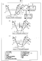
- FIG. 2 is a diagram sequentially illustrating a method of insertion and fixation into the body via a trocar punctured in the body when the in-vivo imaging device 1 is used in laparoscopic surgery.
- trocars 2A to 2C are punctured into the abdominal wall X of the patient.
- those used in the later laparoscopic surgery can be used for introducing the in-vivo imaging device 1.
- the endoscope 4 is installed in the trocar 2A, and the visual field inside the body is secured from the tip of the trocar 2A.
- the endoscope here generally means a rigid endoscope or a laparoscope.
- the in-vivo imaging device 1 held by the forceps 3B is inserted into the body from the trocar 2B.
- the in-vivo imaging device 1 is connected to the side surface near the abdominal wall X of the trocar 2C based on the field of view from the endoscope 4, and the in-vivo imaging device 1 is connected from the forceps 3B. Release.
- the in-vivo imaging device 1 is fixed to the side surface of the trocar 2C.
- the insertion and fixation of the in-vivo imaging device 1 into the body is completed.
- the endoscope 4 is changed from the trocar 2A to the trocar 2C, and the forceps 3A is installed on the trocar 2A.
- the preparation of the laparoscopic surgery which ensures a wide visual field from the in-vivo imaging device 1 is completed.
- FIG. 3 is a diagram illustrating an example of a method of installing the in-vivo imaging device 1 by taking an example of laparoscopic surgery using the in-vivo imaging device 1 as an example.
- 3A to 3C, the forceps 3A and 3B and the endoscope 4 are introduced via the trocars 2A to 2C punctured into the abdominal wall X of the patient, and the forceps are applied to the organ Y.
- An example is laparoscopic surgery in which treatment is performed using 3A and 3B.
- FIG. 3A shows an example in which the in-vivo imaging device 1 is fixed to the side surface in the vicinity of the abdominal wall X of the trocar 2C and the visual field from the in-vivo imaging device 1 is secured, as in FIG. 2E. Yes.
- the video signal from the in-vivo imaging device 1 is transmitted to the in-vivo imaging device control device 5, and the video signal from the endoscope 4 is transmitted to the endoscope control device 6.
- video is displayed on the in-vivo imaging device display device 7A and the endoscope display device 7B, respectively.
- the surgeon can perform an operation while confirming a wide-angle image from the in-vivo imaging device 1 and an image near the distal end of the forceps 3B from the endoscope 4.
- a signal from the in-vivo imaging device 1 is transmitted by wireless communication, and a signal from the endoscope 4 is performed by communication via the cable 8.
- the in-vivo imaging device 1 is fixed to the side surface in the vicinity of the abdominal wall X of the imaging device support 9 for fixing the in-vivo imaging device 1, and the visual field from the in-vivo imaging device 1 is secured.
- An example is drawn.
- the imaging device support 9 may be punctured into the abdominal wall X in advance before introducing the in-vivo imaging device 1 into the abdominal wall X.
- 3C shows an example in which the in-vivo imaging device 1 is fixed to the side surface of the forceps 3A and the visual field from the in-vivo imaging device 1 is secured.
- the field of view that can be secured becomes narrower than the example shown in FIG. 3A, the in-vivo imaging device 1 can be installed in the vicinity of the forceps, so that the state of treatment can be observed in more detail. It is.
- 3A to 3C show examples in which the video signal from the in-vivo imaging device 1 is transmitted to the in-vivo imaging device control device 5 by wireless communication.
- the present invention is not limited to this, and as shown in FIGS. 4A to 4C, the cable 8 is connected from the in-vivo imaging device control device 5 to the in-vivo imaging device 1 via any of the trocars 2A to 2C.
- wired communication may be performed between the in-vivo imaging device 1 and the in-vivo imaging device control device 5.
- the cable 8A may include not only a signal line but also a power line or a gas flow path described later, for example.
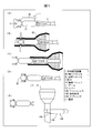
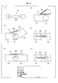
- FIG. 1A to 1E are views showing the internal structure of the in-vivo imaging device 1 viewed from the lower surface, the upper surface, the side surface, the front surface, and the side surface, respectively.
- the in-vivo imaging device 1 includes an imaging unit 10, an arm 11 as a gripping mechanism, and a lever 12 as an operation mechanism.
- the imaging unit 10 controls the main lens 13A and the main imaging device 13B, the internal illumination 14A as the imaging unit, and the sub lens 15A and the sub imaging device 15B as the auxiliary imaging unit.
- a circuit board 16A is provided. Note that the substrate shown in FIG. 1E is an example provided in each of the image sensor or the control circuit, and each substrate may be integrated. In the case of an integrated substrate described later, the substrate 16 is used.
- the main lens 13 ⁇ / b> A is disposed at the end opposite to the arm 11 on the lower surface of the housing 17, and takes in light to the image sensor formed on the substrate 16.
- the internal illumination 14 ⁇ / b> A is disposed on the lower surface of the housing 17.
- As the internal illumination 14A for example, LED illumination can be employed.
- the sub lens 15 ⁇ / b> A is installed at the side end of the housing 17 on the arm 11 side.
- the sub lens 15 ⁇ / b> A takes light from the periphery of the arm 11 into an image sensor formed on the substrate 16 and images the periphery of the arm 11.
- substrates since the internal structure regarding subsequent board
- the arm 11 is disposed at one end of the side surface of the imaging unit 10.
- the arm 11 is movable according to an external force, and fixes the imaging unit 10 in the body by grasping an instrument existing in the body.
- the opening angle of the arm 11 is limited by the housing 17.
- the lever 12 is disposed at one end of the side surface of the imaging unit 10 opposite to the arm 11.
- the lever 12 can be operated to open and close the arm 11 by operating according to an external force.
- the maximum distance D1 between the arms 11 is preferably 3 mm or less in consideration of the diameter of the instrument such as the trocar to be gripped.
- the maximum distance D2 between the levers 12 is 12 mm or less in consideration of gripping using a later-described forceps and the inner diameter of a cylindrical instrument such as a trocar. It is preferable that
- the in-vivo imaging device 1 preferably has a smooth curved surface structure on the outer periphery and does not have an angular portion.
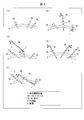
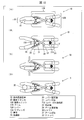
- FIG. 5 is a diagram for explaining in detail how the in-vivo imaging device 1 is inserted into the body through the trocar and the in-vivo imaging device 1 is fixed to the trocar punctured in the body.
- 5A to 5E are views seen from above the in-vivo imaging device 1
- FIG. 5F is a view seen from the side of the in-vivo imaging device 1.
- the in-vivo imaging device 1 is grasped by grasping the lever 12 of the in-vivo imaging device 1 using the forceps 3.
- the lever 12 is operated by the forceps 3
- the arm 11 is operated, and the distance between the arms 11 is increased to D3.
- D3 is preferably 15 mm or more in consideration of the diameter of the trocar to be gripped.
- the in-vivo imaging device 1 held by the forceps 3 is inserted into an insertion trocar 2D punctured in the body.
- the arm 11 is pushed by the inner wall of the insertion trocar 2D and moves in the closing direction indicated by the arrow.
- FIG. 5C when the arm 11 of the in-vivo imaging device 1 passes through the narrow tube of the insertion trocar 2D, the interval between the arms 11 is expanded to D3 again.
- the narrow tube of the fixed trocar 2E comes between the arms 11, and the main lens 13A and the internal illumination 14A are in a direction toward the tip of the fixed trocar 2E.
- the forceps 3 is operated to release the lever 12 from the forceps 3.
- the arm 11 holds the fixed trocar 2E and fixes the imaging unit 10 to the fixed trocar 2E.
- the surgeon can perform a series of operations shown in FIGS. 5A to 5F based on an image obtained from the sub lens 15A. Note that the in-vivo imaging device 1 can be easily removed after the operation by performing the above procedure in reverse.
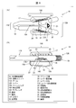
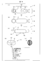
- FIG. 6 is a diagram illustrating a detailed configuration of the in-vivo imaging device 1A according to the second embodiment. 6A is a top view, FIG. 6B is a side view, and both FIG. 6A and FIG. Further, in FIG. 6A, the partition 17A is shown through.
- the in-vivo imaging device 1A includes an imaging unit 10A, an arm 11A as a gripping mechanism, and a lever 12A as an operation mechanism.
- the imaging unit 10 ⁇ / b> A includes a main lens 13 ⁇ / b> A, an in-vivo illumination 14 ⁇ / b> A, and a sub-lens 15 ⁇ / b> A, and incorporates a substrate 16 in a housing 17.
- the inside of the housing 17 is partitioned by a partition 17A.
- a substrate 16 is formed in a space below the partition 17A in the internal space of the housing 17.
- the space in which the substrate 16 is formed is sealed between the outside of the housing 17 and the space above the partition 17 ⁇ / b> A in the internal space of the housing 17.
- the space above the partition 17 ⁇ / b> A is sealed, but there is a gap smaller than the member included in the housing 17 between the outside of the housing 17. You may do it.
- the space where the image pickup device of the housing 17 exists and the space where the gripping mechanism and the operation mechanism exist may be separated from each other with the partition 17A as a boundary.
- the arm 11 ⁇ / b> A includes a tip 18 at the end opposite to the imaging unit 10. It is desirable that the distal end portion 18 bends in a direction in which the arm 11A is closed as compared with other portions of the arm 11A. In a normal state in which the lever 12A is not sandwiched, it is preferable that the tip portions 18 of the two arms 11A partially overlap each other when viewed from the upper surface direction of the in-vivo imaging device.
- the lever 12A is disposed on the opposite side to the arm 11A of the imaging unit 10A.
- the end side surface of the lever 12A opposite to the imaging unit 10 has a structure that can be easily held by forceps, and has, for example, a grip groove 19 as illustrated.
- Each of the two levers 12A is fixed by a lever fixing shaft 20 so as to be rotatable about the lever fixing shaft 20.
- the lever fixing shaft 20 is formed integrally with the housing 17.
- An elastic body (lever elastic body) for connecting the two levers 12A is formed inside the housing 17.
- the elastic body is a lever spring 21, the lever spring 21 and the lever 12 ⁇ / b> A are connected via the lever spring connection portion 21 ⁇ / b> A, and the state where the lever 12 ⁇ / b> A opens from the inside of the housing 17 to the outside is maintained.
- An example is given.
- the two arms 11A and the two levers 12A are connected to each other by a movable shaft 22 so as to be rotatable around the movable shaft 22. Further, between the arm 11A and the lever 12A, an elastic body represented by the connection spring 23 (an elastic body for connection) is formed between a spring connection portion 24 formed on the arm 11A and a different spring connection portion formed on the lever 12A. One is formed so as to be connected to each other.
- the connection spring 23 exerts an elastic force on the arm 11A in the direction in which the arm 11A opens.
- the angle formed between the arm 11A and the lever 12A by the support 26 described later is shown in FIG. Limited to angles.
- the support 26 includes a movable connecting portion 27 formed on the outer surface of the arm 11A and a groove portion 28 formed on the outer surface of the lever 12A in the vicinity of the movable shaft 22. Formed between.
- the support 26 is a hard member that is difficult to bend and stretch.
- the support 26 may be, for example, a resin such as polystyrene or polyvinyl chloride, or a metal such as iron or stainless steel, but a metal having high rigidity such as iron having a Young's modulus of 100 GPa or more is more preferable.
- One end of the support body 26 is connected to the movable connection portion 27, and the support body 26 can rotate around the movable connection portion 27. Further, the other end of the support 26 is fitted in the groove 28 and is movable within the range of the groove 28. For this reason, it is preferable that the surface of the support body 26 is smooth. Detailed operation of the support 26 will be described later.
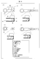
- FIG. 7 is a diagram for explaining the detailed operation of the in-vivo imaging device 1A until the in-vivo imaging device 1A is inserted into the body through the trocar and fixed to the trocar.
- FIGS. 7A to 7D are top views of the in-vivo imaging device 1A shown through the casing 17. In FIG. 7, the substrate 16 is not shown, and only the upper part related to the gripping mechanism and the operating mechanism is shown.
- FIG. 7A is a diagram showing a normal state of the in-vivo imaging device 1A when the lever 12A is not clamped with forceps or the like.
- the lever 12A rotates around the lever fixing shaft 20, and the portion of the lever 12A outside the housing is the housing. It moves in the direction of closing from the inside of 17 toward the outside.
- the arm 11 ⁇ / b> A and the movable shaft 22 move in the direction in which the arm 11 ⁇ / b> A opens due to the elastic force exerted by the connection spring 23.
- the lever spring 21 holds an elastic force in the direction of closing the arm 11A.
- the opening angle of the arm 11 ⁇ / b> A is limited by the housing 17.
- the in-vivo imaging device 1A is inserted into the trocar while holding the lever 12A using forceps.
- the arm 11A is pushed by the inner wall of the trocar and moves in the closing direction by an external force acting in the direction of the arrow.
- the connection spring 23 extends.
- the arm 11A passes through the narrow tube of the trocar, the arm 11A is opened again by the elastic force of the extended connection spring 23, and the in-vivo imaging device 1A returns to the state shown in FIG.
- the forceps are operated so that the narrow tube of the fixed trocar 2E comes between the arms 11A, and the lever 12A is released from the forceps.
- the lever 12A rotates about the lever fixing shaft 20 by the elastic force of the lever spring 21, the lever 12A moves in the direction of opening from the inside of the housing 17 to the outside, and the arm 11A and the movable shaft 22 are moved.
- the arm 11A moves in the closing direction. Accordingly, as shown in FIG. 7D, the arm 11A sandwiches the fixed trocar 2E, and fixes the imaging unit 10A to the fixed trocar 2E.
- the fixed trocar 2E can be restrained from detaching the arm 11A from the fixed trocar 2E by being pinched at a position where the tip 18 of the arm 11A is bent.
- FIG. 8 is a diagram for explaining in detail the mechanism for limiting the arm angle by the support 26.
- FIG. 8A is an enlarged top view of the vicinity of the movable range limiting mechanism 50 in the states of FIGS. 7A, 7B, and 7D
- FIG. 8B is a support 26 of FIG. It is a side view of a side.
- the movable range limiting mechanism 50 includes a support body 26, a movable connecting portion 27, and a groove portion 28, and has a function of limiting the movable range of the arm 11A.
- a specific mechanism of the movable range limiting mechanism 50 will be described.
- the arm 11 ⁇ / b> A exerts a force in the direction of opening around the movable shaft 22 by the elastic force exerted by the connection spring 23.
- one end of the support body 26 is embedded in the groove portion 28 formed in the lever 12A, one end of the support body 26 is restricted from moving toward the lever 12A side than the groove portion 28.
- the angle formed by the arm 11A and the lever 12A is limited to ⁇ 1.
- ⁇ 1 150 ° may be set.
- FIG. 8C is an enlarged top view of the vicinity of the support 26 in the state of FIG. 7C
- FIG. 8D is a side view of the support 26 side of FIG.
- the arm 11A In the state where the in-vivo imaging device 1A holds the trocar as shown in FIG. 7D, the arm 11A is opened by a certain angle. However, the angle formed between the arm 11A and the lever 12A by the support 26 does not become less than ⁇ 1. For this reason, even when the lever 12A is opened, the lever 12A does not return to the same angle as when the trocar is not gripped, and elastic force remains in the lever spring 21. Since this elastic force is directly transmitted to the arm 11A as a force for closing the arm 11A, a force for the arm 11A to grip the fixed trocar 2E is generated, and the imaging unit 10A can be fixed.
- a columnar shape in which the longitudinal direction is arranged perpendicular to the longitudinal direction of the support 26 at both ends like a support rod 26 ⁇ / b> A shown in FIG. May have a part.
- the cylindrical portions at both ends of the support rod 26A are embedded in the movable connection portion 27 and the groove portion 28, respectively.
- the support rod 26A can rotate around the movable connecting portion 27, and slides in the groove 28 as shown in FIGS. 9C to 9F. It is movable.
- a spherical portion may be provided at both ends as in a support rod 26B shown in FIG.
- the spherical portions at both ends of the support rod 26B are embedded in the movable connection portion 27 and the groove portion 28, respectively.
- the support rod 26B can rotate around the movable connecting portion 27, and slides in the groove 28 as shown in FIGS. 10C to 10F. It is movable.
- the both end structure of the support body 26 is not limited to a columnar shape or a spherical shape.
- FIG. 11 is a diagram illustrating a detailed configuration of the in-vivo imaging device 1B according to the third embodiment.
- 11A is a top view
- FIG. 11B is a side view
- the interior of the housing 17 of the in-vivo imaging device 1B is partitioned by a partition 17A.
- FIG. 11A the in-vivo imaging device 1B is shown through the partition 17A.
- the in-vivo imaging device 1B includes an imaging unit 10B, an arm 11B as a gripping mechanism, and a lever 12B as an operation mechanism.
- the in-vivo imaging device 1B is different from the in-vivo imaging device 1A in that the arm 11B is fixed rotatably around the arm fixing shaft 29 by an arm fixing shaft 29 integrated with the housing 17, and the lever 12B via the shaft 30 is fixed. It is a point connected to.
- the two shafts 30 are connected to one of the arms 11B through the arm fixing shaft 29 and are connected to one of the levers 12B through the movable shaft 22 so as to cross each other.
- An arm spring 31 (an arm elastic body) is formed on the arm fixing shaft 29 and is connected to the arm 11 ⁇ / b> B and the shaft 30.
- a stopper 32 is formed on the side surface of the shaft 30 near the arm 11B.
- the arm 11 ⁇ / b> B comes into contact with the stopper 32, so that the movement in the direction in which the angle with the shaft 30 opens is limited.
- the stopper 32 is a hard member that is difficult to bend and stretch.
- FIG. 12 is a diagram illustrating the detailed operation of the in-vivo imaging device 1B until the in-vivo imaging device 1B is inserted into the body through the trocar and fixed to the trocar.
- 12A to 12D are top views of the in-vivo imaging device 1B shown through the casing 17, and the substrate 16 is omitted.
- FIG. 12A is a diagram showing a normal state of the in-vivo imaging device 1B when the lever 12B is not clamped with forceps or the like.
- the lever 12B rotates about the lever fixing shaft 20, and the lever 12B is directed from the inside of the housing 17 to the outside.
- Move in the direction of closing In conjunction with this movement, the two shafts 30 move in the direction in which the end on the lever 12B side is separated, and the arm 11B moves in the opening direction while contacting the stopper 32.
- the lever spring 21 holds an elastic force in the direction of closing the arm 11A.
- the opening angle of the arm 11 ⁇ / b> A is limited by the housing 17.
- the in-vivo imaging device 1B is inserted into the trocar while holding the lever 12B using forceps.
- the arm 11B is pushed by the inner wall of the trocar and moves in the closing direction by an external force acting in the direction of the arrow.
- the arm spring 31 holds an elastic force in the direction in which the arm 11B opens.
- the arm 11B passes through the narrow tube of the trocar, the arm 11B is opened until it again comes into contact with the stopper 32 by the elastic force of the arm spring 31, and the in-vivo imaging device 1B returns to the state shown in FIG.
- the forceps are operated so that the narrow tube of the fixed trocar 2E comes between the arms 11B, and the lever 12B is released from the forceps.
- the lever 12B rotates about the lever fixing shaft 20 by the elastic force of the lever spring 21, the lever 12B moves in the direction of opening from the inside of the housing 17 to the outside, and the arm 11B is pushed by the stopper 32.
- the arm 11B moves in the closing direction.
- the arm 11B clamps the fixed trocar 2E, and fixes the imaging unit 10B to the fixed trocar 2E.
- FIG. 13 is a diagram showing details of the structure and mechanism of the stopper 32.
- FIGS. 13A and 13B are a perspective view of the stopper 32 and a cross-sectional view in a plane perpendicular to the longitudinal direction, respectively.
- the stopper 32 has an outer shape that is bent into a dogleg shape, and has a shape in which a cross section is a concave shape.
- the size of the recess of the stopper 32 is larger than the width between the arm 11 ⁇ / b> B and the shaft 30.
- FIG. 13C is an enlarged top view of the vicinity of the stopper 32 in the states of FIGS. 12A, 12B, and 12D
- FIG. 13D is a side view of the stopper 32 side of FIG. It is.
- the arm 11 ⁇ / b> B is exerted by the elastic force exerted by the arm spring 31 in a direction to open around the arm fixing shaft 29.
- the opening angle of the arm 11B is limited.
- FIG. 13E is an enlarged top view of the vicinity of the stopper 32 in the state of FIG. 12C
- FIG. 13F is a side view of the stopper 32 side of FIG.
- the arm 11B is pushed by the inner wall of the trocar and moves in the closing direction. In this case, the arm 11B can move away from the stopper 32.
- the arm 11B In the state where the in-vivo imaging device 1B holds the trocar as shown in FIG. 12D, the arm 11B is opened by a certain angle. However, the opening angle of the arm 11B is limited by the stopper 32. For this reason, similarly to the arm 11A, a force that the arm 11B grips the fixed trocar 2E is generated, and the imaging unit 10B can be fixed.
- the movable range limiting mechanism using the support shown in FIGS. 8 to 10 and the stopper shown in FIG. 13 are not limited to the specific configurations 1 and 2 of the arm system, but can be applied to both. .
- FIG. 14 is a diagram illustrating the configuration of the in-vivo imaging device 1C according to the fourth embodiment.
- 14A to 14D are views showing a lower surface, an upper surface, a side surface, and a front surface of the in-vivo imaging device 1C, respectively, and
- FIG. 14E is a cross-sectional view of the annular arm 11C.
- the in-vivo imaging device 1C includes an annular arm 11C as a gripping mechanism, as shown in FIGS. .
- the annular arm 11C is, for example, a substantially circular annular member, and is formed at the side end of the imaging unit 10C so that the direction of the central axis of the annular arm 11C is parallel to the vertical direction of the in-vivo imaging device 1C. Yes.
- the annular arm 11C is made of an elastic soft member and is deformed by an external force. However, when the external force is removed, the annular arm 11C is restored to its original shape.
- the diameter R1 of the annular arm is preferably 15 mm or more in consideration of the diameter of the trocar to be gripped.
- the annular arm 11C includes a balloon 33 on the inner surface thereof.
- the balloon 33 can be expanded and contracted by the inflow and outflow of gas, and the expansion and contraction are operated through the operation of the lever 12C.
- FIG. 15 is a diagram for explaining in detail how the in-vivo imaging device 1C is inserted into the body via the trocar and the in-vivo imaging device 1C is fixed to the trocar punctured in the body.
- 15A to 15D are views seen from above the in-vivo imaging device 1C.
- 15E is a cross-sectional view of the annular arm 11C when the balloon 33 is expanded, and
- FIG. 15G is a view seen from the side of the in-vivo imaging device 1C.
- H is a top view of the vicinity of the annular arm 11C when the in-vivo imaging device 1C is fixed to a different fixed trocar.
- the forceps 3 are used to hold the in-vivo imaging device 1C by holding the lever 12C of the in-vivo imaging device 1C.
- the in-vivo imaging device 1C held by the forceps 3 is inserted into an insertion trocar 2D punctured in the body.
- the annular arm 11C is pushed by the inner wall of the insertion trocar 2D and deforms in the closing direction indicated by the arrow.
- the annular arm 11C of the in-vivo imaging device 1C passes through the thin tube of the insertion trocar 2D, the annular arm 11 is restored again to the shape shown in FIG.
- FIG. 15D the forceps 3 are operated so that the thin tube of the fixed trocar 2E passes through the ring of the annular arm 11C, and the lever 12C is released from the forceps 3.
- gas is sent into the balloon 33 and the balloon 33 expands. Therefore, as shown in FIGS. 15F and 15G, the balloon 33 of the annular arm 11C fastens the fixed trocar 2E, and fixes the imaging unit 10C to the fixed trocar 2E.
- the surgeon can perform a series of operations shown in FIGS. 15A to 15G based on an image obtained from the sub lens 15A.
- the balloon 33 tightens the fixed trocar 2F and the in-vivo imaging device. It is possible to fix 1C. Therefore, the in-vivo imaging device 1C can be fixed regardless of the diameter of the trocar that fixes the in-vivo imaging device 1C.
- FIG. 16 is a diagram for explaining in detail the procedure of the operation of the balloon 33 of the in-vivo imaging device 1C.
- FIGS. 16A to 16D are a top view of the in-vivo imaging device 1C and a gas carrier, respectively. An enlarged transparent view as an example of the mechanism 34 is shown.
- the in-vivo imaging device 1C includes a gas transport mechanism 34 inside the housing 17.
- the gas transport mechanism 34 includes a gas storage chamber 35 and a gas flow path 36, and the gas flow path 36 includes a rotary valve 37 as a valve for controlling the gas flow.
- a gas such as carbon dioxide is stored in a compressed state.
- a hole through which gas can pass is formed on the surface of the gas storage chamber 35 that contacts the gas flow path 36.
- the gas flow path 36 is provided with a deaeration hole 38 through which gas communicates with the outside on a side surface in contact with the rotary valve 37. Further, the gas flow path 36 is provided with a balloon-side air hole 39 in fluid communication with the balloon 33 on the side surface opposite to the side where the rotary valve 37 is formed.
- the rotary valve 37 has a mechanism that rotates 90 ° counterclockwise when viewed from the top surface direction each time one of the operations for gripping or releasing the lever 12C is performed.
- the rotary valve 37 includes therein a rotary valve flow path 40 that is bent at a right angle.
- the rotary valve channel 40 has a hole through which gas can pass on the side surface of the rotary valve 37, and fluidly communicates with the outside of the rotary valve 37.
- the gas transport mechanism 34 is in the state shown in FIG. 16A, and one of the two holes of the rotary valve channel 40 communicates with the deaeration hole 38, while the other is the gas channel 36. It is in contact with the side and closed. Since the hole of the gas storage chamber 35 is closed by the side surface of the rotary valve 37, the gas storage chamber 35 is sealed.
- the rotary valve 37 further rotates 90 ° as shown in FIG. .
- one end of the rotary valve channel 40 communicates with the gas channel 36, and the other end communicates with a hole formed in the gas storage chamber 35.
- the compressed gas in the gas storage chamber 35 flows out in the direction of the arrow through the rotary valve channel 40, the gas channel 36 and the balloon side air hole 39.
- the balloon 33 is expanded by the gas flowing from the balloon-side air hole 39, the fixed trocar 2E is tightened, and the imaging unit 10C is fixed to the fixed trocar 2E.
- the rotary valve 37 further rotates 90 ° as shown in FIG.
- One end of the rotary valve channel 40 communicates with the gas channel 36 and the other end communicates with the deaeration hole 38.
- the gas in the balloon 33 flows in the direction of the arrow through the balloon side air hole 39, the gas flow path 36 and the rotary valve flow path 40, and flows out from the deaeration hole 38 to the outside.
- the balloon 33 is deflated and can be removed from the fixed trocar 2E.
- the gas transport mechanism 34 controls the gas flow between the gas storage chamber 35, the balloon 33, and the outside of the imaging unit 10C according to the operation from the lever 12C, and controls the expansion and contraction of the balloon 33. .
- the expansion and contraction of the balloon 33 may be controlled by sending the gas directly into the balloon 33 or sucking the gas from the balloon 33 using a cable or the like from outside the body. In this case, the gas transport mechanism 34 is not necessary.
- FIG. 17 is a diagram illustrating the configuration of the in-vivo imaging device 1D according to the fifth embodiment.
- 17A to 17D are diagrams showing the lower surface, the upper surface, the side surface, and the front surface of the in-vivo imaging device 1D, respectively.
- the in-vivo imaging device 1D includes an annular arm 11D as a gripping mechanism.
- the annular arm 11D is an elliptical annular member in which the insertion direction of the in-vivo imaging device 1D is a major axis in a normal state where the lever 12D is not gripped.
- the annular arm 11D is formed at the end of the side surface of the imaging unit 10D so that the direction of the central axis of the annular arm 11D is parallel to the vertical direction of the in-vivo imaging device 1D.
- the short axis length R2 of the annular arm 11D is preferably 3 mm or less in consideration of the diameter of the trocar to be gripped.
- the annular arm 11D is made of an elastic soft member and is deformed by an external force. When the external force is removed, the annular arm 11D is restored to its original shape. Furthermore, the in-vivo imaging device 1D has a mechanism in which the annular arm 11D is deformed by an operation of gripping the lever 12D with forceps or the like and becomes substantially circular. When the lever 12D is opened, the annular arm 11D is deformed again and restored to the original elliptical shape.
- FIG. 18 is a diagram for explaining in detail how the in-vivo imaging device 1D is inserted into the body through the trocar and the in-vivo imaging device 1D is fixed to the trocar punctured in the body.
- 18A to 18E are views seen from above the in-vivo imaging device 1D
- FIG. 18F is a view seen from the side of the in-vivo imaging device 1D.
- the forceps 3 are used to hold the in-vivo imaging device 1D by holding the lever 12D of the in-vivo imaging device 1D.
- the annular arm 11D is deformed into a substantially circular shape.
- the diameter R3 of the annular arm 11D is preferably 15 mm or more in consideration of the diameter of the trocar to be gripped.
- the in-vivo imaging device 1D can pass through the insertion trocar 2D in the same manner as the in-vivo imaging device 1C.
- the forceps 3 are operated so that the thin tube of the fixed trocar 2E passes through the ring of the annular arm 11D, and the lever 12D is released from the forceps 3.
- the annular arm 11D tightens the fixed trocar 2E by the force that the annular arm 11D tries to restore to the original elliptical shape. Therefore, as shown in FIGS. 18E and 18F, the imaging unit 10D is fixed to the fixed trocar 2E.
- the surgeon can perform a series of operations shown in FIGS. 18A to 18F based on an image obtained from the sub lens 15A.
- FIG. 19 is a diagram illustrating a configuration of an in-vivo imaging device 1E according to Modification 1.
- FIGS. 19A to 19D are views showing a lower surface, an upper surface, a side surface, and a front surface of the in-vivo imaging device 1E, respectively.
- the in-vivo imaging device 1E includes a rhombus arm 11E as a gripping mechanism.
- the rhombus arm 11E is a rhombus-shaped annular member having a long diagonal line in the insertion direction of the in-vivo imaging device 1E in a normal state in which the lever 12E is not gripped and having apexes connected by a rotation axis.
- the ends of the plurality of arms are connected to each other on the rotating shaft, so that the plurality of arms form a rhombus shape.
- the direction of the central axis of the rhombus arm 11E is formed in parallel with the vertical direction of the in-vivo imaging device 1E.
- the short axis length D4 is preferably 3 mm or less in consideration of the diameter of the trocar to be gripped.
- the rhombus arm 11E expands and contracts due to an external force that changes the angle around the rotation axis. However, when the external force is removed, the rhombus arm 11E restores its original shape. Furthermore, the in-vivo imaging device 1E has a mechanism in which the rhombus arm 11E is deformed by an operation of gripping the lever 12E with forceps or the like and becomes a substantially square shape. When the lever 12E is opened, the rhombus arm 11E is deformed again and restored to the original rhombus.
- the in-vivo imaging device 1E can be fixed to the fixed trocar 2E by the same operation as the in-vivo imaging device 1D, as shown in FIGS.
- the length D5 of one side of the rhombus arm 11E obtained by gripping the lever 12E with the forceps 3 and deformed into a substantially square shape takes the diameter of the trocar to be gripped into consideration. , 15 mm or more is preferable.
- FIG. 21 is a diagram illustrating the configuration of the in-vivo imaging device 1F according to the sixth embodiment and the fixing method to the fixed trocar 2E.
- FIG. 21A is a top view of the in-vivo imaging device 1F.
- 21B and 21C show a top view and a side view of the in-vivo imaging device 1F when the in-vivo imaging device 1F is fixed to the fixed trocar 2E, respectively.
- an arm 11F is provided as a gripping mechanism.
- the arm 11F has a balloon 33 on the inner surface of the tip, and can be expanded and contracted by operating the lever 12F.
- the balloon 33 may be expanded and contracted using the gas transport mechanism 34 of the in-vivo imaging device 1C.
- the arm 11 ⁇ / b> F includes an arm angle adjustment unit 41. By operating the arm angle adjustment unit 41, the angle formed by the two arms 11F is appropriately changed.
- the arm angle adjustment unit 41 is used to pass the trocar in a state where the angle formed by the arm 11F is minimized. After the arm 11F passes through the trocar, the angle formed by the two arms 11F is expanded to an angle at which the narrow tube of the fixed trocar 2E enters between the two arms 11F using the arm angle adjusting unit 41. In this state, the in-vivo imaging device 1F is operated so that the thin tube of the fixed trocar 2E comes between the two arms 11F, and the balloon 33 is expanded. As a result, as shown in FIGS. 21B and 21C, the in-vivo imaging device 1F is fixed to the fixed trocar 2E.
- (Modification of arm) 22A to 22I are diagrams showing the arm 11G and the arm 11H that can be used for both the arm 11A of the in-vivo imaging device 1A and the arm 11B of the in-vivo imaging device 1B.
- 22 (A) to 22 (C) are enlarged views of the upper surface, side surface, and front surface of the arm 11G attached to the in-vivo imaging device, respectively.
- the arm 11G has a distal end portion 18 that is bent in the closing direction of the arm 11G as compared with other portions of the arm 11G.
- the tip portions 18 of the two arms 11G partially overlap each other when viewed from the upper surface direction of the in-vivo imaging device.
- the in-vivo imaging device By configuring the gripping mechanism of the in-vivo imaging device in the shape of the arm 11G, the in-vivo imaging device can be easily fixed to the trocar regardless of the diameter as shown in FIGS. 22 (D) and 22 (E). It can be configured.
- 22 (F) and 22 (G) are enlarged views of the upper surface and the front surface of the arm 11H attached to the in-vivo imaging device, respectively.
- the arm 11H has a plurality of corrugated portions 18A to 18D which are undulated in the longitudinal direction of the arm. Different wavy portions have shapes in which the waving interval increases toward the tip.
- the fixed trocar 2G When it is desired to fix the in-vivo imaging device to the fixed trocar 2G having a large diameter as shown in FIG. 22 (H), the fixed trocar 2G is held near the tip of the arm 11H and held between the wavy portions 18A having a large undulation interval. When it is desired to fix the in-vivo imaging device to the fixed trocar 2H having a small diameter shown in (I) of FIG. 22, the fixed trocar 2H is sandwiched between the wavy portions 18D that are close to the root of the arm 11H and have a small waving interval.
- the in-vivo imaging device can be easily fixed to the trocar regardless of the diameter by appropriately selecting the position at which the trocar is gripped from the wavy portions with different undulation intervals of the arm 11G.
- the in-vivo imaging device of aspect 1 is an in-vivo imaging device that can be introduced into the body, an imaging unit having an imaging mechanism, a main lens, and a housing, a movable first mechanism that attaches to an object, and the first mechanism. And a movable second mechanism for operating.
- the first mechanism is linked to the second mechanism.
- the housing has first and second side surfaces (both may be curved surfaces) facing each other, the first mechanism intersects with the first side surface, and the second mechanism intersects with the second side surface.
- the optical axis of the main lens included in the imaging mechanism is a direction along the normal line of the lower surface of the housing.
- the main lens included in the imaging mechanism is arranged such that the distance from the second side surface is smaller than the distance from the first side surface.
- the imaging mechanism includes a sub-lens that enables imaging of the first mechanism.
- the second mechanism includes two levers that form a pair, and at least the tip of each lever is located outside the housing.
- the first mechanism includes two arms that form a pair, and these arms sandwich the object by a portion located outside the housing including the tip.
- the two arms move in a closing direction when receiving an inward external force.
- the second mechanism includes a lever elastic body disposed between the two levers.
- each of the two levers rotates about a fixed rotation axis.
- each of the two arms rotates about a movable rotation axis, and each arm is connected to one lever on the movable rotation axis.
- a connecting elastic body that connects one of the two levers and one of the two arms, and a connecting elastic body that connects the other of the two levers and the other of the two arms, Including.
- each of the two arms rotates about a fixed rotation axis.
- a shaft that connects one of the two levers and one of the two arms, a shaft that connects the other of the two levers and the other of the two arms, and provided for each arm, And an arm elastic body connecting the arm and the shaft.
- the rotation shafts of the two levers are integrated with the side surface of the housing.
- each arm located outside the housing is bent inward.
- the bent corner of each arm is rounded.
- a plurality of curved portions having different radii of curvature are provided in portions located outside the casing of each arm.
- a support is provided for each arm, a movable connecting portion is provided on one of the arm and a lever connected to the arm, and a groove is provided on the other, and one end of the support is connected to the movable connecting portion. The other end of the support is slidably fitted in the groove.
- a stopper is provided for each arm, and the stopper comes into contact with the side surface of the arm near the rotation axis when the opening of the arm reaches a certain range.
- the outer surface of the tip of each lever is uneven, or the outer surface of the tip of each lever is covered with a flexible material.
- irregularities are formed inside the portion of each arm located outside the housing, or the inside of the portion located outside the housing of each arm is covered with a flexible material.
- the first mechanism includes an annular arm that fits into the object.
- the first mechanism has a balloon inside the annular arm that is deflated when the distance between the tip portions of the two levers is reduced by an external force, and is inflated when the external force is removed, The object is clamped by an annular arm and a balloon.
- a gas storage section, a deaeration hole, and a rotating flow path that rotates according to the distance between the tip portions of the two levers are provided in the casing.
- the balloon is deflated when the vent hole and the deaeration hole are connected via a rotating flow path, and when the vent hole and the gas storage unit are connected via a rotating flow path. Swell.
- the imaging unit includes a power source and a wireless communication circuit.
- the power is turned on by operating the second mechanism.
- the imaging unit is connected to a cable that can be inserted into a tubular instrument.
- the imaging unit includes an illumination device that illuminates at least the lower side of the housing.
- the outer peripheral surface of the housing is a curved surface.
- At least one of the first and second mechanisms and the housing are fixed.
- the inside of the housing is sealed with a partition plate extending from one side surface of the housing to the other side surface in which the first and second mechanisms are present and a control circuit for the imaging mechanism is present. Divided into space.
- the partition plate is parallel to the lower surface of the casing, and the sealing space is located on the lower surface side in the casing.
- the bent corner of each bent arm is rounded.
- the two levers can be operated by a medical instrument introduced into the body.
- the first mechanism is configured such that the ends of the plurality of arms are connected to each other on the rotation shaft, the plurality of arms form a rhombus shape, and the angle extends around the rotation shaft. And a rhombus arm, and the object is sandwiched by the expansion and contraction of the rhombus arm.
- the present invention is not limited to the above-described embodiments, and embodiments obtained by appropriately combining technical means disclosed in different embodiments are also included in the technical scope of the present invention. Furthermore, a new technical feature can be formed by combining the technical means disclosed in each embodiment.
Landscapes
- Health & Medical Sciences (AREA)
- Life Sciences & Earth Sciences (AREA)
- Surgery (AREA)
- Nuclear Medicine, Radiotherapy & Molecular Imaging (AREA)
- Biomedical Technology (AREA)
- Optics & Photonics (AREA)
- Pathology (AREA)
- Radiology & Medical Imaging (AREA)
- Biophysics (AREA)
- Engineering & Computer Science (AREA)
- Physics & Mathematics (AREA)
- Heart & Thoracic Surgery (AREA)
- Medical Informatics (AREA)
- Molecular Biology (AREA)
- Animal Behavior & Ethology (AREA)
- General Health & Medical Sciences (AREA)
- Public Health (AREA)
- Veterinary Medicine (AREA)
- Endoscopes (AREA)
Abstract
使い勝手のよい体内撮像装置を実現することを目的として、体内に導入可能な体内撮像装置(1A)であって、撮像機構およびレンズ並びに筐体を有する撮像ユニット(10A)と、対象物(2E)に取り付く可動的な第1機構(11A)と、前記第1機構を操作するための可動的な第2機構(12A)とを備える体内撮像装置(1A)を提供する。
Description
本発明は体内撮像装置に関する。
内視鏡手術は、患者を開腹することなく、検査や治療処置を行う低侵襲性の手術である。内視鏡手術では、鉗子等の処置具と内視鏡とが別々に患者の体内に導入され、術者は、体内に挿入された処置具の先端部分の画像を内視鏡の観察視野内に捕らえ、処置具による患部の処置状態を内視鏡によって観察しながらその処置作業を行う。内視鏡手術では、患者の腹部等における体壁(例えば腹壁)に穿刺した筒を通して処置具及び内視鏡を体内に導入する。なお、この筒は、いわゆるトロッカと称される管状部材である。
術者は、内視鏡を臓器に近づけて画像を拡大して、臓器の切開または縫合を行うが、このとき、術者の視野が非常に狭くなってしまう。このため、作業領域外の状態(例えば、作業領域外の処置具の動き、出血状態、ガーゼ等の残留物の残留状態)を広く把握できるような体内撮像装置が要望されている。
特許文献1には、固定化ユニットを備え、体内腔の所望の場所に固定することが可能である、生体内撮像装置が開示されている。また、特許文献2には、体内に穿刺したマニピュレータの先端に搭載される撮像カプセルが開示されている。
特許文献1に記載の撮像装置は、体内での固定が難しいと考えられる。また、特許文献2に記載の撮像カプセルは、穿刺したマニピュレータの先端に固定する必要があるため、既存の手術器具以外に専用のマニピュレータを必要とする。さらに、マニピュレータを穿刺するための穴を腹壁に開ける必要があるため、患者および術者への負担が増加する。
本発明は上記課題を鑑みてなされたものであり、患者および術者への負担を低減した、使い勝手のよい体内撮像装置を実現することを目的とする。
本発明の一態様に係る体内撮像装置は、体内に導入可能な体内撮像装置であって、撮像素子およびレンズ並びに筐体を有する撮像ユニットと、対象物に取り付く可動的な第1機構と、前記第1機構を操作するための可動的な第2機構とを備える。
前記第1および第2機構によって体内の対象物(トロッカー、カニューレ、鉗子等)に容易に固定可能な、使い勝手のよい体内撮像装置を実現することができる。
以下、本発明の実施の形態について、詳細に説明する。ただし、以下の実施形態に記載されている構成およびその組み合わせは、特に特定的な記載がない限り、本発明の範囲を当該構成のみに限定する趣旨ではなく、単なる説明例に過ぎない。なお、以下で説明する図面においては、同一機能を有するものは同一符号を付け、その繰り返しの説明は省略する。
〔実施形態1〕
本発明の一実施形態について、図1~5に基づいて説明する。
本発明の一実施形態について、図1~5に基づいて説明する。
(体内撮像装置の導入法)
本発明の一実施形態に係る体内撮像装置1は、体内に穿刺されたトロッカ等の筒状の器具を介して、体内への挿入および固定と、体内からの脱去とが可能である。体内撮像装置1の体内への挿入および固定の方法を、図2を用いて説明する。図2は、体内撮像装置1を腹腔鏡手術において使用する場合の、体内に穿刺されたトロッカを介した、体内への挿入および固定の方法を順に示す図である。
本発明の一実施形態に係る体内撮像装置1は、体内に穿刺されたトロッカ等の筒状の器具を介して、体内への挿入および固定と、体内からの脱去とが可能である。体内撮像装置1の体内への挿入および固定の方法を、図2を用いて説明する。図2は、体内撮像装置1を腹腔鏡手術において使用する場合の、体内に穿刺されたトロッカを介した、体内への挿入および固定の方法を順に示す図である。
始めに、図2の(A)に示すように、患者の腹壁Xにトロッカ2A~2Cを穿刺する。トロッカ2A~2Cは、後の腹腔鏡手術において使用されるものを、体内撮像装置1の導入に使用する事が可能である。
次に、図2の(B)に示すように、トロッカ2Aに内視鏡4を設置し、トロッカ2Aの先端から体内の視野を確保する。ここでいう内視鏡は、一般的には硬性内視鏡、または腹腔鏡を意味する。この状態において、鉗子3Bにて把持した体内撮像装置1をトロッカ2Bから体内に挿入する。そして、図2の(C)に示すように、体内撮像装置1を内視鏡4からの視野をもとに、トロッカ2Cの腹壁Xの近傍側面に接続し、鉗子3Bから体内撮像装置1を離す。こうして、図2の(D)に示すように、トロッカ2Cの側面に体内撮像装置1を固定する。以上により、体内撮像装置1の体内への挿入および固定が完了する。
さらに、内視鏡4をトロッカ2Aからトロッカ2Cに付け替え、トロッカ2Aに鉗子3Aを設置する。これにより、図2の(E)に示すように、体内撮像装置1から広い視野を確保する腹腔鏡手術の準備が完了する。
(体内撮像装置の設置例)
図3は、体内撮像装置1の設置方法の例を、実際に体内撮像装置1を使用した腹腔鏡手術の様子を例に挙げて説明する図である。図3の(A)~(C)においては、何れも患者の腹壁Xに穿刺されたトロッカ2A~2Cを介して、鉗子3A、3Bと内視鏡4とを導入し、臓器Yに対し鉗子3A、3Bを用いて処置を行う腹腔鏡手術を例に挙げている。
図3は、体内撮像装置1の設置方法の例を、実際に体内撮像装置1を使用した腹腔鏡手術の様子を例に挙げて説明する図である。図3の(A)~(C)においては、何れも患者の腹壁Xに穿刺されたトロッカ2A~2Cを介して、鉗子3A、3Bと内視鏡4とを導入し、臓器Yに対し鉗子3A、3Bを用いて処置を行う腹腔鏡手術を例に挙げている。
図3の(A)においては、図2の(E)と同様に、トロッカ2Cの腹壁Xの近傍側面に体内撮像装置1を固定し、体内撮像装置1からの視野を確保した例を描いている。本実施形態においては、体内撮像装置1からの映像の信号は体内撮像装置制御機器5へ、内視鏡4からの映像の信号は内視鏡制御機器6へそれぞれ送信される。
送信された映像信号をもとに、それぞれ、体内撮像装置用表示装置7Aと内視鏡用表示装置7Bとに映像が映し出される。これにより、術者は、体内撮像装置1から広角の映像を、内視鏡4から鉗子3Bの先端近傍の映像を確認しつつ手術を行える。なお、体内撮像装置1からの信号は無線通信によって送信され、内視鏡4からの信号はケーブル8を介した通信によって行われる。
一方、図3の(B)においては、体内撮像装置1を固定するための撮像装置支持具9の腹壁Xの近傍側面に体内撮像装置1を固定し、体内撮像装置1からの視野を確保した例を描いている。撮像装置支持具9は、体内撮像装置1を腹壁X内に導入する前に、あらかじめ腹壁Xに穿刺されてもよい。
さらに、図3の(C)においては、鉗子3Aの側面に体内撮像装置1を固定し、体内撮像装置1からの視野を確保した例を描いている。この場合、図3の(A)に示した例よりも、確保可能な視野は狭くなるものの、体内撮像装置1を鉗子の近傍に設置できるため、処置の様子をより詳細に観察することが可能である。
図3の(A)~(C)においては、体内撮像装置1からの映像信号が無線通信によって体内撮像装置制御機器5に送信される例を挙げている。しかし、これに限られず、図4の(A)~(C)に示すように、体内撮像装置制御機器5からケーブル8を、トロッカ2A~2Cの何れかを介して体内撮像装置1へと接続し、体内撮像装置1と体内撮像装置制御機器5との間において有線通信を行ってもよい。なお、このケーブル8Aは、信号線のみならず、例えば、電源線または後述するガスの流路を含んでいてもよい。
(体内撮像装置の基本構造)
続いて、体内撮像装置1の基本構造を、図1を用いて説明する。図1の(A)~(E)は、体内撮像装置1の下面、上面、側面、前面、及び側面から見た内部構造をそれぞれ示す図である。
続いて、体内撮像装置1の基本構造を、図1を用いて説明する。図1の(A)~(E)は、体内撮像装置1の下面、上面、側面、前面、及び側面から見た内部構造をそれぞれ示す図である。
図1の(A)~(C)に示すように、体内撮像装置1は、撮像ユニット10と、把持機構としてアーム11と、操作機構としてのレバー12とを備える。
図1の(E)を参照すると、撮像ユニット10は、撮像部として、メインレンズ13Aおよびメイン撮像素子13Bと、体内照明14Aと、補助撮像部として、サブレンズ15Aおよびサブ撮像素子15Bと、制御回路基板16Aを備える。なお、図1の(E)に示す基板は撮像素子または制御回路の各々に設けている例であり、各基板は一体化してもよく、後述する一体化した基板の場合は基板16とする。
メインレンズ13Aは筐体17下面のアーム11と逆側の端部に配置され、基板16に形成された撮像素子へと光を取り込む。体内照明14Aは筐体17下面に配置される。体内照明14Aとしては、例えば、LED照明を採用できる。サブレンズ15Aは筐体17のアーム11側の側面端部に設置される。サブレンズ15Aはアーム11の周囲からの光を、基板16に形成された撮像素子へと取り込み、アーム11の周囲を撮像する。なお、以降の基板に関する内部構造は同様であるため、詳細な記載は省略する。
アーム11は撮像ユニット10の側面の一端に配置される。アーム11は外力にしたがって可動であり、体内に存在する器具を把持することにより、撮像ユニット10を体内に固定する。アーム11の開放する角度は、筐体17によって制限される。
レバー12は撮像ユニット10の側面の、アーム11とは逆側の一端に配置される。レバー12は外力にしたがって操作されることにより、アーム11の開閉を操作可能である。
レバー12が把持されていない場合の、アーム11の間隔の最大距離D1は把持するトロッカ等の器具の径を考慮して、3mm以下であることが好ましい。また、レバー12が把持されていない場合の、レバー12の間隔の最大距離D2は、後述する鉗子を使用して把持することと、トロッカ等の筒状の器具の内径とを考慮し、12mm以下であることが好ましい。
なお、体内撮像装置1は、外周に滑らかな曲面構造を有し、角張った部位を有さないことが好ましい。
(体内撮像装置の導入の概要)
図5はトロッカを介して体内撮像装置1を体内に挿入し、体内に穿刺されたトロッカに体内撮像装置1を固定する様子を詳細に説明する図である。なお、図5の(A)~(E)は、体内撮像装置1の上方から見た図であり、図5の(F)は、体内撮像装置1の側面から見た図である。
図5はトロッカを介して体内撮像装置1を体内に挿入し、体内に穿刺されたトロッカに体内撮像装置1を固定する様子を詳細に説明する図である。なお、図5の(A)~(E)は、体内撮像装置1の上方から見た図であり、図5の(F)は、体内撮像装置1の側面から見た図である。
始めに、図5の(A)に示すように、鉗子3を用いて、体内撮像装置1のレバー12を把持することにより、体内撮像装置1を把持する。このとき、レバー12が鉗子3によって操作されることにより、アーム11が操作され、アーム11の間隔がD3まで広がる。D3は、把持するトロッカの径を考慮して、15mm以上であることが好ましい。このとき、アーム11は筐体17によって広がる角度が制限されるため、アーム11はさらに間隔が広がる方向には動かない。
次に、図5の(B)に示すように、鉗子3によって把持された体内撮像装置1を、体内に穿刺された挿入トロッカ2Dに挿入する。挿入トロッカ2Dの細管を体内撮像装置1が通る際に、アーム11は挿入トロッカ2Dの内壁に押されて、矢印によって示す閉じる方向に動く。図5の(C)に示すように、体内撮像装置1のアーム11が挿入トロッカ2Dの細管を通過しきると、アーム11の間隔は再びD3まで広がる。
そして、図5の(D)に示すように、アーム11の間に固定トロッカ2Eの細管が来るように、かつ、メインレンズ13Aと体内照明14Aとが固定トロッカ2Eの先端に向かう方向となるように鉗子3を操作し、鉗子3からレバー12を開放する。これにより、図5の(E)および(F)に示すように、アーム11が固定トロッカ2Eを挟持して、撮像ユニット10を固定トロッカ2Eに固定する。図5の(A)~(F)に示した一連の操作を、術者はサブレンズ15Aから得られる映像を基に行うことができる。なお、上述の手順を逆に行うことで、容易に術後の体内撮像装置1の脱去を行える。
〔実施形態2〕
本発明の他の実施形態について、図6~図8に基づいて説明する。なお、説明の便宜上、前記実施形態にて説明した部材と同じ機能を有する部材については、同じ符号を付記し、その説明を省略する。後の実施形態においても同様である。
本発明の他の実施形態について、図6~図8に基づいて説明する。なお、説明の便宜上、前記実施形態にて説明した部材と同じ機能を有する部材については、同じ符号を付記し、その説明を省略する。後の実施形態においても同様である。
(アーム方式の具体構成1)
本実施形態においては、実施形態1における体内撮像装置1の具体的な例を、体内撮像装置1Aを挙げて説明する。図6は、実施形態2に係る体内撮像装置1Aの詳細な構成を説明する図である。図6の(A)は上面図であり、(B)は側面図であり、(A)および(B)ともに筐体17の上面を透過させて示している。さらに、図6の(A)においては、仕切り17Aを透過させて示している。
本実施形態においては、実施形態1における体内撮像装置1の具体的な例を、体内撮像装置1Aを挙げて説明する。図6は、実施形態2に係る体内撮像装置1Aの詳細な構成を説明する図である。図6の(A)は上面図であり、(B)は側面図であり、(A)および(B)ともに筐体17の上面を透過させて示している。さらに、図6の(A)においては、仕切り17Aを透過させて示している。
図6に示すように、体内撮像装置1Aは、撮像ユニット10Aと、把持機構としてアーム11Aと、操作機構としてのレバー12Aとを備える。図6を参照すると、撮像ユニット10Aは、メインレンズ13Aと、体内照明14Aと、サブレンズ15Aとを備え、基板16を筐体17に内蔵する。
筐体17の内部は、仕切り17Aによって仕切られている。筐体17の内部空間のうち、仕切り17Aの下方側の空間には、基板16が形成されている。基板16が形成された空間は、筐体17の外部と、筐体17の内部空間のうち、仕切り17Aの上方側の空間との密閉がなされている。筐体17の内部空間のうち、仕切り17Aの上方側の空間においては、密閉されることが望ましいが、筐体17の外部との間に、筐体17に含まれる部材よりも小さな隙間が存在していてもよい。また、仕切り17Aを境に、筐体17の撮像素子の存在する空間と、把持機構および操作機構の存在する空間とを分離してもよい。
アーム11Aは撮像ユニット10とは逆側の端部に、先端部18を備える。先端部18はアーム11Aの他の部位と比較して、アーム11Aが閉じる方向に折れ曲がっていることが望ましい。レバー12Aを挟持しない通常の状態において、2本のアーム11Aの先端部18は体内撮像装置の上面方向からみて互いに一部が重なっていることが好ましい。
レバー12Aは撮像ユニット10Aのアーム11Aとは逆側に配置されている。レバー12Aの撮像ユニット10とは逆側の端部側面は、鉗子によって挟持しやすくする構造を有し、例えば、図示するようなグリップ溝19を有する。2本のレバー12Aはそれぞれ、レバー固定軸20によって、レバー固定軸20を中心として回転可能に固定される。レバー固定軸20は筐体17と一体的に形成される。また、筐体17の内部において、2本のレバー12Aの間を接続する弾性体(レバー用弾性体)が形成されている。本実施形態においては、弾性体をレバーばね21とし、レバーばね接続部21Aを介してレバーばね21とレバー12Aとを接続し、レバー12Aが筐体17の内部から外部に向かって開く状態を維持している例を挙げている。
2本のアーム11Aと2本のレバー12Aとは、可動軸22のよってそれぞれが1本ずつ、可動軸22を中心に回転可能に接続されている。さらに、アーム11Aとレバー12Aとの間には、接続ばね23に代表される弾性体(接続用弾性体)が、アーム11Aに形成されたばね接続部24とレバー12Aに形成された異なるばね接続部25との間を接続するように、それぞれ1本ずつ形成されている。接続ばね23は、アーム11Aが開く方向に、アーム11Aに対して弾性力を及ぼすが、後述する支持体26によって、アーム11Aとレバー12Aとのなす角度は、図6の(A)に示される角度に制限される。
支持体26は、図6の(B)に示すように、可動軸22近傍において、アーム11Aの外側面に形成された可動接続部27と、レバー12Aの外側面に形成された溝部28との間に形成される。支持体26は、湾曲および伸縮しにくい硬質な部材である。支持体26としては、例えば、ポリスチレンまたはポリ塩化ビニル等の樹脂、もしくは鉄またはステンレス等の金属であってもよいが、ヤング率が100GPa以上ある鉄等の、剛性の高い金属がより好ましい。
支持体26の一端は、可動接続部27に接続され、支持体26は可動接続部27を中心に回転可能である。また、支持体26の他端は、溝部28の中にはめ込まれており、溝部28の範囲内において可動である。このため、支持体26の表面は滑らかであることが好ましい。支持体26の詳細な動作については後述する。
(アーム方式の具体構成1の動作)
図7は、体内撮像装置1Aがトロッカを介して体内に挿入されトロッカに固定されるまでの、体内撮像装置1Aの詳細な動作について説明する図である。図7の(A)~(D)は、何れも筐体17を透過させて示した体内撮像装置1Aの上面図である。なお、図7においては、基板16を図示せず、把持機構と操作機構とに関係する上部部分のみを図示する。
図7は、体内撮像装置1Aがトロッカを介して体内に挿入されトロッカに固定されるまでの、体内撮像装置1Aの詳細な動作について説明する図である。図7の(A)~(D)は、何れも筐体17を透過させて示した体内撮像装置1Aの上面図である。なお、図7においては、基板16を図示せず、把持機構と操作機構とに関係する上部部分のみを図示する。
図7の(A)はレバー12Aを鉗子等で挟持しない場合の、体内撮像装置1Aの通常の状態を示す図である。この状態から鉗子等を用いてレバー12Aを挟持すると、図7の(B)に示すように、レバー12Aはレバー固定軸20を中心に回転し、レバー12Aの筐体外部にある部分が筐体17の内部から外部に向かって閉じる方向に動く。この動きに連動してアーム11Aと可動軸22とは、接続ばね23の及ぼす弾性力により、アーム11Aが開く方向に動く。このとき、レバーばね21には、アーム11Aを閉じる方向への弾性力が保持される。また、アーム11Aは筐体17によって開く角度が制限される。
次に、鉗子を用いてレバー12Aを挟持したまま、トロッカ内部に体内撮像装置1Aを挿入する。体内撮像装置1Aがトロッカの細管を通る際、アーム11Aがトロッカの内壁に押されて、矢印の方向に働く外力によって閉じる方向に動く。このとき、接続ばね23は伸長する。アーム11Aがトロッカの細管を通り切ると、アーム11Aは伸長した接続ばね23の弾性力によって再び開かれ、体内撮像装置1Aは図7の(B)に示した状態に戻る。
最後に、アーム11Aの間に固定トロッカ2Eの細管が来るように鉗子を操作し、鉗子からレバー12Aを開放する。これにより、レバーばね21の弾性力により、レバー12Aはレバー固定軸20を中心に回転し、レバー12Aが筐体17の内部から外部に向かって開く方向に動き、アーム11Aと可動軸22とが、アーム11Aの閉じる方向に動く。これにより、図7の(D)に示すように、アーム11Aが固定トロッカ2Eを挟持して、撮像ユニット10Aを固定トロッカ2Eに固定する。このとき、固定トロッカ2Eはアーム11Aの先端部18が折れ曲がる箇所において挟持されることにより、固定トロッカ2Eからアーム11Aが外れることを抑制できる。
(支持体26によるアーム角度の制限)
図8は支持体26によるアーム角度の制限の機構を詳細に説明する図である。
図8は支持体26によるアーム角度の制限の機構を詳細に説明する図である。
図8の(A)は図7の(A)、(B)、および(D)の状態における可動域制限機構50近傍を拡大した上面図であり、(B)は(A)の支持体26側の側面図である。可動域制限機構50は、支持体26と、可動接続部27と、溝部28とからなり、アーム11Aの可動域を制限する機能を有する。以下に、可動域制限機構50の具体的な機構を説明する。
アーム11Aは、接続ばね23の及ぼす弾性力によって、可動軸22を中心に開く方向へ力が働いている。しかし、支持体26の一端がレバー12Aに形成された溝部28に埋め込まれているため、支持体26の一端は溝部28よりもレバー12A側への動きを制限されている。このため、アーム11Aとレバー12Aとのなす角度は、θ1に制限される。例えば、θ1=150°に設定されてもよい。
図8の(C)は図7の(C)の状態における支持体26近傍を拡大した上面図であり、(D)は(C)の支持体26側の側面図である。このとき、アーム11Aはトロッカの内壁に押され、閉じる方向に動くため、アーム11Aには可動軸22においてレバー12Aとの角度が開く方向に力が働く。この場合、支持体26の溝部28側の一端は、溝部28のアーム11A側の端部まで移動できる。このため、アーム11Aとレバー12Aとのなす角度は、支持体26の溝部28側の一端が移動できる限界位置における角度である、θ2までである。例えば、θ2=180°に設定されてもよい。
図7の(D)に示すような、体内撮像装置1Aがトロッカを把持している状態においては、アーム11Aがある角度だけ開いた状態となる。しかし、支持体26により、アーム11Aとレバー12Aとが成す角度は、θ1未満にならない。このため、レバー12Aが開放された場合でも、トロッカを把持していない状態と同じ角度までレバー12Aは元に戻らず、レバーばね21には弾性力が残存する。この弾性力はアーム11Aを閉じる力として、アーム11Aに直接伝わるため、アーム11Aが固定トロッカ2Eを把持する力が発生し、撮像ユニット10Aを固定することが可能である。
支持体26のより具体的な構造例としては、図9の(A)に示す支持棒26Aのように、両端部に、長手方向が支持体26の長手方向と垂直に配置された、円柱状部を有していてもよい。支持棒26Aの両端の円柱状部は、それぞれ可動接続部27と溝部28とに埋め込まれる。支持棒26Aは、図9の(B)に示すように、可動接続部27を軸に回転可能であり、図9の(C)~(F)に示すように、溝部28においてスライドするように可動である。
支持体26の他の例としては、図10の(A)に示す支持棒26Bのように、両端部に球状部を有していてもよい。支持棒26Bの両端の球状部は、それぞれ可動接続部27と溝部28とに埋め込まれる。支持棒26Bは、図10の(B)に示すように、可動接続部27を軸に回転可能であり、図10の(C)~(F)に示すように、溝部28においてスライドするように可動である。なお、支持体26の両端構造は、円柱形状または球形状に限定するものではない。
〔実施形態3〕
本発明の他の実施形態について、図11および図12に基づいて説明する。
本発明の他の実施形態について、図11および図12に基づいて説明する。
(アーム方式の具体構成2)
図11は、実施形態3に係る体内撮像装置1Bの詳細な構成を説明する図である。図11の(A)は上面図であり、(B)は側面図であり、(A)および(B)ともに筐体17の上面を透過させて示している。体内撮像装置1Aと同様に、体内撮像装置1Bの筐体17の内部は仕切り17Aによって仕切られている。図11の(A)においては、仕切り17Aを透過させて、体内撮像装置1Bを示している。
図11は、実施形態3に係る体内撮像装置1Bの詳細な構成を説明する図である。図11の(A)は上面図であり、(B)は側面図であり、(A)および(B)ともに筐体17の上面を透過させて示している。体内撮像装置1Aと同様に、体内撮像装置1Bの筐体17の内部は仕切り17Aによって仕切られている。図11の(A)においては、仕切り17Aを透過させて、体内撮像装置1Bを示している。
図11に示すように、体内撮像装置1Bは、撮像ユニット10Bと、把持機構としてアーム11Bと、操作機構としてのレバー12Bとを備える。体内撮像装置1Bが体内撮像装置1Aと異なる点は、アーム11Bが筐体17と一体化したアーム固定軸29によって、アーム固定軸29を中心に回転可能に固定され、シャフト30を介してレバー12Bと接続されている点である。
2本のシャフト30はアーム固定軸29を介してアーム11Bの1本と接続し、可動軸22を介してレバー12Bの1本と、互いが交差するようにそれぞれ接続する。アーム固定軸29には、アームばね31(アーム用弾性体)が形成され、アーム11Bとシャフト30とに接続される。
シャフト30のアーム11B近傍の側面には、ストッパ32が形成される。アーム11Bは、ストッパ32に当接することにより、シャフト30との角度が開く方向への動きが制限される。ストッパ32は、湾曲および伸縮しにくい硬質な部材である。
(アーム方式の具体構成2の動作)
図12は、体内撮像装置1Bがトロッカを介して体内に挿入されトロッカに固定されるまでの、体内撮像装置1Bの詳細な動作について説明する図である。図12の(A)~(D)は、何れも筐体17を透過させて示した体内撮像装置1Bの上面図であり、基板16を省略して示している。
図12は、体内撮像装置1Bがトロッカを介して体内に挿入されトロッカに固定されるまでの、体内撮像装置1Bの詳細な動作について説明する図である。図12の(A)~(D)は、何れも筐体17を透過させて示した体内撮像装置1Bの上面図であり、基板16を省略して示している。
図12の(A)はレバー12Bを鉗子等で挟持しない場合の、体内撮像装置1Bの通常の状態を示す図である。この状態から鉗子等を用いてレバー12Bを挟持すると、図12の(B)に示すように、レバー12Bはレバー固定軸20を中心に回転し、レバー12Bが筐体17の内部から外部に向かって閉じる方向に動く。この動きに連動して、2本のシャフト30はレバー12B側の端部が離れる方向にそれぞれ動き、アーム11Bはストッパ32に当接しながら開く方向に動く。このとき、レバーばね21には、アーム11Aを閉じる方向への弾性力が保持される。また、アーム11Aは筐体17によって開く角度が制限される。
次に、鉗子を用いてレバー12Bを挟持したまま、トロッカ内部に体内撮像装置1Bを挿入する。体内撮像装置1Bがトロッカの細管を通る際、アーム11Bがトロッカの内壁に押されて、矢印の方向に働く外力によって閉じる方向に動く。このとき、アームばね31にはアーム11Bが開く方向への弾性力が保持される。アーム11Bがトロッカの細管を通り切ると、アーム11Bはアームばね31の弾性力によって、再びストッパ32に当接するまで開かれ、体内撮像装置1Bは図12の(B)に示した状態に戻る。
最後に、アーム11Bの間に固定トロッカ2Eの細管が来るように鉗子を操作し、鉗子からレバー12Bを開放する。これにより、レバーばね21の弾性力により、レバー12Bはレバー固定軸20を中心に回転し、レバー12Bが筐体17の内部から外部に向かって開く方向に動き、アーム11Bがストッパ32に押され、アーム11Bの閉じる方向に動く。これにより、図12の(D)に示すように、アーム11Bが固定トロッカ2Eを挟持して、撮像ユニット10Bを固定トロッカ2Eに固定する。
(可動域制限機構の構造および機構)
図13は、ストッパ32の構造と機構との詳細を示す図である。図13の(A)および(B)はそれぞれ、ストッパ32の斜視図および長手方向と垂直な面における断面図である。ストッパ32は、くの字に折れ曲がった外形を有しており、断面が凹形状となる形状を有する。ストッパ32の凹部の寸法はアーム11Bとシャフト30との幅よりも大きい。
図13は、ストッパ32の構造と機構との詳細を示す図である。図13の(A)および(B)はそれぞれ、ストッパ32の斜視図および長手方向と垂直な面における断面図である。ストッパ32は、くの字に折れ曲がった外形を有しており、断面が凹形状となる形状を有する。ストッパ32の凹部の寸法はアーム11Bとシャフト30との幅よりも大きい。
図13の(C)は図12の(A)、(B)、および(D)の状態におけるストッパ32近傍を拡大した上面図であり、(D)は(C)のストッパ32側の側面図である。このとき、アーム11Bは、アームばね31の及ぼす弾性力によって、アーム固定軸29を中心に開く方向へ力が働いている。しかし、アーム11Bはストッパ32に押されるため、アーム11Bの開く角度は制限される。
図13の(E)は図12の(C)の状態におけるストッパ32近傍を拡大した上面図であり、(F)は(E)のストッパ32側の側面図である。このとき、アーム11Bはトロッカの内壁に押され、閉じる方向に動く。この場合、アーム11Bはストッパ32から離れて動くことができる。
図12の(D)に示すような、体内撮像装置1Bがトロッカを把持している状態においては、アーム11Bがある角度だけ開いた状態となる。しかし、ストッパ32により、アーム11Bが開く角度は制限される。このため、アーム11Aと同様に、アーム11Bが固定トロッカ2Eを把持する力が発生し、撮像ユニット10Bを固定することが可能である。
なお、図8から図10に示す支持体を用いた可動域制限機構と、図13に示すストッパとは、アーム方式の具体構成1および2のそれぞれに限定せず、両方に適用できるものである。
〔実施形態4〕
本発明の他の実施形態について、図14~図16に基づいて説明する。
本発明の他の実施形態について、図14~図16に基づいて説明する。
(環状アーム方式の具体構成1)
図14は、実施形態4に係る体内撮像装置1Cの構成を説明する図である。図14の(A)~(D)は、体内撮像装置1Cの下面、上面、側面、および前面をそれぞれ示す図であり、(E)は環状アーム11Cの断面図である。
図14は、実施形態4に係る体内撮像装置1Cの構成を説明する図である。図14の(A)~(D)は、体内撮像装置1Cの下面、上面、側面、および前面をそれぞれ示す図であり、(E)は環状アーム11Cの断面図である。
体内撮像装置1Cが体内撮像装置1と異なる点の1つは、図14の(A)~(C)に示すように、体内撮像装置1Cが把持機構として環状アーム11Cを備えている点である。
環状アーム11Cは、例えば、略円形の環状の部材であり、撮像ユニット10Cの側面端部に、環状アーム11Cの中心軸の方向が体内撮像装置1Cの上下方向と平行になるように形成されている。環状アーム11Cは弾性を有する柔らかい部材からなり、外力によって変形するが、外力を取り除くと元の形状に復元する。環状アームの直径R1は、把持するトロッカの径を考慮して、15mm以上であることが好ましい。
図14の(E)に示すように、環状アーム11Cは、その内側面にバルーン33を備える。バルーン33はガスの流入および流出により、拡張および収縮が可能であり、レバー12Cの操作を通じて拡張および収縮が操作される。
(環状アーム方式の具体構成1の動作)
図15はトロッカを介して体内撮像装置1Cを体内に挿入し、体内に穿刺されたトロッカに体内撮像装置1Cを固定する様子を詳細に説明する図である。なお、図15の(A)~(D)、(F)は、体内撮像装置1Cの上方から見た図である。図15の(E)は、バルーン33の拡張時の環状アーム11Cの断面図であり、(G)は、体内撮像装置1Cの側面から見た図である。(H)は、体内撮像装置1Cを異なる固定トロッカに固定する場合における、環状アーム11C近傍の上面図である。
図15はトロッカを介して体内撮像装置1Cを体内に挿入し、体内に穿刺されたトロッカに体内撮像装置1Cを固定する様子を詳細に説明する図である。なお、図15の(A)~(D)、(F)は、体内撮像装置1Cの上方から見た図である。図15の(E)は、バルーン33の拡張時の環状アーム11Cの断面図であり、(G)は、体内撮像装置1Cの側面から見た図である。(H)は、体内撮像装置1Cを異なる固定トロッカに固定する場合における、環状アーム11C近傍の上面図である。
始めに、図15の(A)に示すように、鉗子3を用いて、体内撮像装置1Cのレバー12Cを把持することにより、体内撮像装置1Cを把持する。次に、図15の(B)に示すように、鉗子3によって把持された体内撮像装置1Cを、体内に穿刺された挿入トロッカ2Dに挿入する。挿入トロッカ2Dの細管を体内撮像装置1Cが通る際に、環状アーム11Cは挿入トロッカ2Dの内壁に押されて、矢印によって示す閉じる方向に変形する。図15の(C)に示すように、体内撮像装置1Cの環状アーム11Cが挿入トロッカ2Dの細管を通過しきると、環状アーム11は再び図15の(A)に示す形状に復元する。
そして、図15の(D)に示すように、環状アーム11Cの環に固定トロッカ2Eの細管が通るように鉗子3を操作し、鉗子3からレバー12Cを開放する。この操作より、図15の(E)に示すように、バルーン33にガスが送り込まれ、バルーン33は拡張する。このため、図15の(F)および(G)に示すように、環状アーム11Cのバルーン33が固定トロッカ2Eを締め付けて、撮像ユニット10Cを固定トロッカ2Eに固定する。図15の(A)~(G)に示した一連の操作を、術者はサブレンズ15Aから得られる映像を基に行うことができる。
また、図15の(H)に示すように、体内撮像装置1Cを固定するトロッカの径が、固定トロッカ2Fのように細い場合であっても、バルーン33が固定トロッカ2Fを締め付けて体内撮像装置1Cを固定することが可能である。このため、体内撮像装置1Cを固定するトロッカの径によらず、体内撮像装置1Cを固定することが可能である。
(バルーン33の操作)
図16は、体内撮像装置1Cのバルーン33の操作の手順について詳細に説明するための図であり、図16の(A)~(D)はそれぞれ、体内撮像装置1Cの上面図と、ガス搬送機構34の一例となる拡大透過図とを示す。
図16は、体内撮像装置1Cのバルーン33の操作の手順について詳細に説明するための図であり、図16の(A)~(D)はそれぞれ、体内撮像装置1Cの上面図と、ガス搬送機構34の一例となる拡大透過図とを示す。
図16の(A)に示すように、体内撮像装置1Cは筐体17内部にガス搬送機構34を備える。ガス搬送機構34は、ガス貯蔵室35と、ガス流路36とを備え、ガス流路36は内部に、ガスの流動を制御する弁として回転弁37を備える。ガス貯蔵室35には、例えば、二酸化炭素等のガスが圧縮された状態で貯蔵されている。図16においては図示しないが、ガス貯蔵室35のガス流路36と接する面には、ガスが通過できる孔が形成されている。
ガス流路36は、回転弁37と接する側面に、ガスが外部と連通する脱気孔38を備える。さらにガス流路36は、バルーン33と流体的に連通するバルーン側空気孔39を回転弁37が形成されている側と逆側の側面に備えている。
回転弁37は、レバー12Cが把持される、または開放される操作の内、何れかを一度行われるたびに、上面方向からみて反時計回りに90°回転する機構を有する。回転弁37は、直角に折れ曲がった回転弁流路40を内部に備える。回転弁流路40は回転弁37の側面に、ガスが通過できる孔を有し、流体的に回転弁37の外部と連通する。
始めに、ガス搬送機構34は、図16の(A)に示す状態にあり、回転弁流路40の2つの孔の内、一方は脱気孔38と連通するが、他方はガス流路36の側面に当接し閉じられている。ガス貯蔵室35の孔は、回転弁37の側面によって塞がれているため、ガス貯蔵室35は密閉されている。
次に、図16の(B)に示すように、鉗子3を用いてレバー12Cを把持すると、回転弁37が90°回転する。このとき、回転弁流路40の一端は、ガス貯蔵室35に形成された孔と連通するが、他端はガス流路36の側面に当接し閉じられている。このため、ガス貯蔵室35の密閉は引き続いて保持されている。
体内撮像装置1Cがトロッカ内部を通過し、固定トロッカ2Eが環状アーム11Cに通された後、レバー12Cを開放すると、図16の(C)に示すように、さらに回転弁37が90°回転する。このとき、回転弁流路40の一端はガス流路36と連通し、他端はガス貯蔵室35に形成された孔と連通する。このため、ガス貯蔵室35内の圧縮されたガスは、回転弁流路40とガス流路36とバルーン側空気孔39とを通って、矢印の方向へ流出する。バルーン側空気孔39から流れてきたガスによってバルーン33は拡張し、固定トロッカ2Eを締め付けて、撮像ユニット10Cを固定トロッカ2Eに固定する。
最後に、術後に体内撮像装置1Cを脱去するために、再び鉗子3を用いてレバー12Cを把持すると、図16の(D)に示すように、さらに回転弁37が90°回転する。回転弁流路40の一端はガス流路36と連通し、他端は脱気孔38と連通する。このため、バルーン33内のガスは、バルーン側空気孔39とガス流路36と回転弁流路40とを通って矢印の方向に流れ、脱気孔38から外部へ流出する。これにより、バルーン33は収縮し、固定トロッカ2Eからの脱去が可能となる。
上述のように、ガス搬送機構34は、レバー12Cからの操作にしたがって、ガス貯蔵室35とバルーン33と撮像ユニット10Cの外部とのガスの流動を制御し、バルーン33の拡張および収縮を制御する。
なお、体外からケーブル等を使用して、直接バルーン33にガスを送り込む、またはバルーン33からガスを吸引することにより、バルーン33の拡張および収縮を制御してもよい。この場合、ガス搬送機構34は不要となる。
〔実施形態5〕
本発明の他の実施形態について、図17および図18に基づいて説明する。
本発明の他の実施形態について、図17および図18に基づいて説明する。
(環状アーム方式の具体構成2)
図17は、実施形態5に係る体内撮像装置1Dの構成を説明する図である。図17の(A)~(D)は、体内撮像装置1Dの下面、上面、側面、および前面をそれぞれ示す図である。
図17は、実施形態5に係る体内撮像装置1Dの構成を説明する図である。図17の(A)~(D)は、体内撮像装置1Dの下面、上面、側面、および前面をそれぞれ示す図である。
体内撮像装置1Dが体内撮像装置1Cと異なる点の1つは、図14の(A)~(C)に示すように、体内撮像装置1Dが把持機構として環状アーム11Dを備えている点である。環状アーム11Dは、レバー12Dを把持しない通常の状態において、体内撮像装置1Dの挿入方向が長軸となる楕円形の環状部材である。環状アーム11Dは、撮像ユニット10Dの側面端部に、環状アーム11Dの中心軸の方向が体内撮像装置1Dの上下方向と平行になるように形成されている。環状アーム11Dの短軸長R2は、把持するトロッカの径を考慮して、3mm以下であることが好ましい。
環状アーム11Dは弾性を有する柔らかい部材からなり、外力によって変形するが、外力を取り除くと元の形状に復元する。さらに、体内撮像装置1Dは、レバー12Dを鉗子等によって把持する操作により、環状アーム11Dが変形し、略円形となる機構を有する。レバー12Dを開放する操作を行うと、環状アーム11Dは再び変形し、元の楕円形に復元する。
(環状アーム方式の具体構成2の動作)
図18はトロッカを介して体内撮像装置1Dを体内に挿入し、体内に穿刺されたトロッカに体内撮像装置1Dを固定する様子を詳細に説明する図である。なお、図18の(A)~(E)は、体内撮像装置1Dの上方から見た図であり、図18の(F)は、体内撮像装置1Dの側面から見た図である。
図18はトロッカを介して体内撮像装置1Dを体内に挿入し、体内に穿刺されたトロッカに体内撮像装置1Dを固定する様子を詳細に説明する図である。なお、図18の(A)~(E)は、体内撮像装置1Dの上方から見た図であり、図18の(F)は、体内撮像装置1Dの側面から見た図である。
始めに、図18の(A)に示すように、鉗子3を用いて、体内撮像装置1Dのレバー12Dを把持することにより、体内撮像装置1Dを把持する。この操作により、環状アーム11Dは略円形に変形する。この場合の環状アーム11Dの直径R3は、把持するトロッカの径を考慮して、15mm以上であることが好ましい。図18の(B)および(C)に示すように、体内撮像装置1Dは体内撮像装置1Cと同様に、挿入トロッカ2D内部を通過することができる。
そして、図18の(D)に示すように、環状アーム11Dの環に固定トロッカ2Eの細管が通るように鉗子3を操作し、鉗子3からレバー12Dを開放する。この操作より、図18の(E)に示すように、環状アーム11Dが元の楕円形に復元しようとする力によって、環状アーム11Dが固定トロッカ2Eを締め付ける。このため、図18の(E)および(F)に示すように、撮像ユニット10Dを固定トロッカ2Eに固定する。図18の(A)~(F)に示した一連の操作を、術者はサブレンズ15Aから得られる映像を基に行うことができる。
〔変形例1〕
本発明の変形例について、図19および図20に基づいて説明する。
本発明の変形例について、図19および図20に基づいて説明する。
(菱形アーム)
図19は、変形例1に係る体内撮像装置1Eの構成を説明する図である。図19の(A)~(D)は、体内撮像装置1Eの下面、上面、側面、および前面をそれぞれ示す図である。
図19は、変形例1に係る体内撮像装置1Eの構成を説明する図である。図19の(A)~(D)は、体内撮像装置1Eの下面、上面、側面、および前面をそれぞれ示す図である。
体内撮像装置1Eが体内撮像装置1Dと異なる点の1つは、図19の(A)~(C)に示すように、体内撮像装置1Eが把持機構としてひし形アーム11Eを備えている点である。ひし形アーム11Eは、レバー12Eを把持しない通常の状態において、体内撮像装置1Eの挿入方向に長軸の対角線を有し、頂点が回転軸によって接続されたひし形の環状部材である。ひし形アーム11Eは、回転軸において複数のアームの端部が互いに接続されることにより、前記複数のアームがひし形形状を形成する。撮像ユニット10Eの側面端部に、ひし形アーム11Eの中心軸の方向が体内撮像装置1Eの上下方向と平行になるように形成されている。ひし形アーム11Eの対角線の内、短軸の長さD4は、把持するトロッカの径を考慮して、3mm以下であることが好ましい。
ひし形アーム11Eは外力によって、回転軸周りの角度が変化することにより伸縮するが、外力を取り除くと元の形状に復元する。さらに、体内撮像装置1Eは、レバー12Eを鉗子等によって把持する操作により、ひし形アーム11Eが変形し、略正方形となる機構を有する。レバー12Eを開放する操作を行うと、ひし形アーム11Eは再び変形し、元のひし形に復元する。
体内撮像装置1Eは、図20の(A)から(F)に示すように、体内撮像装置1Dと同様の操作によって、固定トロッカ2Eに固定する事が可能である。このとき、図20の(A)に示すように、レバー12Eを鉗子3で把持し、略正方形状に変形させたひし形アーム11Eの一辺の長さD5は、把持するトロッカの径を考慮して、15mm以上であることが好ましい。
〔実施形態6〕
本発明の他の実施形態について、図21に基づいて説明する。
本発明の他の実施形態について、図21に基づいて説明する。
(バルーン付アーム方式の具体構成)
図21は、実施形態6に係る体内撮像装置1Fの構成および固定トロッカ2Eへの固定方法を説明する図である。図21の(A)は、体内撮像装置1Fの上面図である。また、図21の(B)および(C)はそれぞれ、体内撮像装置1Fを固定トロッカ2Eに固定した場合における体内撮像装置1Fの、上面図および側面図を示す。
図21は、実施形態6に係る体内撮像装置1Fの構成および固定トロッカ2Eへの固定方法を説明する図である。図21の(A)は、体内撮像装置1Fの上面図である。また、図21の(B)および(C)はそれぞれ、体内撮像装置1Fを固定トロッカ2Eに固定した場合における体内撮像装置1Fの、上面図および側面図を示す。
体内撮像装置1Fが体内撮像装置1と異なる点の1つは、把持機構としてアーム11Fを備える点である。アーム11Fは、先端の内側面にバルーン33を有し、レバー12Fの操作によって拡張および収縮させることができる。バルーン33の拡張および収縮の方法は、体内撮像装置1Cのガス搬送機構34を用いたものでもよい。さらに、アーム11Fはアーム角度調節部41を備える。アーム角度調節部41を操作することにより、2本のアーム11Fが成す角度は適宜変更される。
体内撮像装置1Fを体内に挿入する場合、図21の(A)に示すように、アーム角度調節部41を使用して、アーム11Fが成す角度を最小とした状態において、トロッカを通過させる。アーム11Fがトロッカを通過した後、アーム角度調節部41を使用して、2本のアーム11Fの間に固定トロッカ2Eの細管が入る角度まで、2本のアーム11Fのなす角度を広げる。この状態において、2本のアーム11Fの間に固定トロッカ2Eの細管が来るように体内撮像装置1Fを操作して、バルーン33を拡張させる。これにより、図21の(B)および(C)に示すように、固定トロッカ2Eに体内撮像装置1Fを固定する。
〔変形例2〕
本発明の他の変形例について、図22に基づいて説明する。
本発明の他の変形例について、図22に基づいて説明する。
(アームの変形例)
図22の(A)~(I)は、体内撮像装置1Aのアーム11Aおよび体内撮像装置1Bのアーム11B何れにも採用可能である、アーム11Gおよびアーム11Hを示す図である。
図22の(A)~(I)は、体内撮像装置1Aのアーム11Aおよび体内撮像装置1Bのアーム11B何れにも採用可能である、アーム11Gおよびアーム11Hを示す図である。
図22の(A)~(C)はそれぞれ、体内撮像装置に取り付けられたアーム11Gの上面、側面、および前面を拡大した図である。アーム11Gは、アーム11Aと同様に、アーム11Gの他の部位と比較して、アーム11Gが閉じる方向に折れ曲がっている、先端部18を有する。トロッカを挟持しない通常の状態において、2本のアーム11Gの先端部18は体内撮像装置の上面方向からみて互いに一部が重なっている。
体内撮像装置の把持機構を、アーム11Gの形状に構成することにより、図22の(D)および(E)に示すように、径の大小にかかわらず、体内撮像装置をトロッカに簡便に固定できる構成とすることが可能である。
図22の(F)および(G)はそれぞれ、体内撮像装置に取り付けられたアーム11Hの上面、および前面を拡大した図である。アーム11Hは、アームの長手方向に波打った、複数の波状部18A~18Dを有する。異なる波状部においては、波打つ間隔が先端に行くほど大きくなる形状を有している。
図22の(H)に示す、径の大きい固定トロッカ2Gに体内撮像装置を固定したい場合、固定トロッカ2Gをアーム11Hの先端に近く、波打つ間隔が大きい波状部18Aにおいて挟持する。図22の(I)に示す、径の小さい固定トロッカ2Hに体内撮像装置を固定したい場合、固定トロッカ2Hをアーム11Hの根本に近く、波打つ間隔が小さい波状部18Dにおいて挟持する。
以上のように、トロッカを把持する位置を、アーム11Gの波打つ間隔が異なる波状部の中から適宜選択することによって、径の大小にかかわらず、体内撮像装置をトロッカに簡便に固定できる。
〔まとめ〕
態様1の体内撮像装置は、体内に導入可能な体内撮像装置であって、撮像機構およびメインレンズ並びに筐体を有する撮像ユニットと、対象物に取り付く可動的な第1機構と、前記第1機構を操作するための可動的な第2機構とを備える。
態様1の体内撮像装置は、体内に導入可能な体内撮像装置であって、撮像機構およびメインレンズ並びに筐体を有する撮像ユニットと、対象物に取り付く可動的な第1機構と、前記第1機構を操作するための可動的な第2機構とを備える。
態様2では、前記第1機構が第2機構に連動する。
態様3では、前記筐体は互いに向かい合う第1および第2側面(ともに曲面でもよい)を有し、前記第1機構は第1側面と交わり、前記第2機構は第2側面と交わる。
態様4では、前記撮像機構に含まれるメインレンズの光軸は、前記筐体の下面の法線に沿う方向である。
態様5では、前記撮像機構に含まれるメインレンズは、前記第1側面との距離よりも前記第2側面との距離の方が小さくなるように配されている。
態様6では、前記撮像機構は、前記第1機構の撮像を可能とするサブレンズを含む。
態様7では、前記第2機構は、対となる2つのレバーを含み、各レバーの少なくとも先端部が筐体外部に位置する。
態様8では、前記第1機構は、対となる2つのアームを含み、これらアームは、先端部を含む筐体外部に位置する部分によって対象物を挟み込む。
態様9では、外力をかけて前記2つのレバーの先端部間の距離を縮めると前記2つのアームが開く向きに動き、前記外力を除去すると前記2つのアームが閉じる方向に動く。
態様10では、前記2つのアームは、内向きの外力を受けると閉じる方向に動く。
態様11では、前記第2機構は、前記2つのレバー間に配されたレバー用弾性体を含む。
態様12では、前記2つのレバーそれぞれが固定の回転軸を中心に回動する。
態様13では、前記2つのアームそれぞれが可動の回転軸を中心に回動し、この可動の回転軸において各アームが1つのレバーに接続されている。
態様14では、前記2つのレバーの1つと前記2つのアームの1つとを繋ぐ接続用弾性体と、前記2つのレバーのもう1つと前記2つのアームのもう1つとを繋ぐ接続用弾性体とを含む。
態様15では、前記2つのアームそれぞれが固定の回転軸を中心に回動する。
態様16では、前記2つのレバーの1つと前記2つのアームの1つとを繋ぐシャフトと、前記2つのレバーのもう1つと前記2つのアームのもう1つとを繋ぐシャフトと、アームごとに設けられ、アームおよびシャフトを接続するアーム用弾性体とを含む。
態様17では、前記2つのレバーそれぞれの回転軸が、筐体の側面に一体化されている。
態様18では、各アームの筐体外部に位置する部分が内側に屈曲している。
態様19では、各アームの屈曲コーナが丸められている。
態様20では、各アームの筐体外部に位置する部分に、曲率半径の異なる湾曲部が複数設けられている。
態様21では、アームごとに支持体が設けられ、アームおよびこれに繋がるレバーの一方に可動接続部が設けられるとともに他方に溝部が設けられ、前記支持体の一端部が前記可動接続部に接続され、前記支持体の他端部が前記溝部にスライド可能に嵌め込まれている。
態様22では、アームごとにストッパが設けられ、前記ストッパは、アームの開きが一定範囲に達するとアームの回転軸近傍の側面に当接する。
態様23では、各レバーの先端部の外側表面に凹凸が形成されているか、あるいは各レバーの先端部の外側表面が柔軟素材で覆われている。
態様24では、各アームの筐体外部に位置する部分の内側に凹凸が形成されているか、あるいは各アームの筐体外部に位置する部分の内側が柔軟素材で覆われている。
態様25では、前記第1機構は、対象物に嵌める環状のアームを備える。
態様26では、前記第1機構は、前記環状のアームの内側に、外力によって前記2つのレバーの先端部間の距離を縮めれば萎み、前記外力を除去すれば膨らむバルーンを有し、前記環状のアームおよびバルーンによって対象物を締め付ける。
態様27では、前記筐体内に、ガス貯蔵部と、脱気穴と、前記2つのレバーの先端部間の距離に応じて回転する回転流路とが設けられている。
態様28では、前記バルーンは、その通気穴と前記脱気穴とが回転流路を介して連結されると萎み、前記通気穴とガス貯蔵部とが回転流路を介して連結されると膨らむ。
態様29では、前記撮像ユニットは、電源および無線通信回路を備える。
態様30では、前記第2機構の操作によって電源がオンされる。
態様31では、前記撮像ユニットは、管状器具に挿通可能なケーブルに接続されている。
態様32では、前記撮像ユニットは、少なくとも筐体の下側を照らす照明装置を備える。
態様33では、前記筐体の外周面が曲面である。
態様34では、前記第1および第2機構の少なくとも一方と前記筐体とが固定されている。
態様35では、前記筐体の内部は、筐体の一方の側面から他方の側面に到る仕切り板によって前記第1および第2機構が存在する空間と撮像機構の制御回路が存在する密閉性の空間とに分けられる。
態様36では、前記仕切り板は前記筐体の下面と平行であり、前記密閉性の空間は、前記筐体の内部において下面側に位置する。
様態37では、筐体が仕切られた位置において、分離可能である。
態様38では、屈曲した各アームの屈曲コーナが丸みを有している。
態様39では、前記2つのレバーは、体内に導入される医療器具によって操作可能である。
態様40では、前記第1機構は、回転軸において複数のアームの端部が互いに接続されることにより、前記複数のアームがひし形形状を形成し、回転軸周りの角度が変化することにより伸縮する、ひし形アームを含み、該ひし形アームの伸縮動作によって対象物を挟み込む。
本発明は上述した実施形態に限定されるものではなく、異なる実施形態にそれぞれ開示された技術的手段を適宜組み合わせて得られる実施形態についても本発明の技術的範囲に含まれる。さらに、各実施形態にそれぞれ開示された技術的手段を組み合わせることにより、新しい技術的特徴を形成することができる。
1 体内撮像装置
2 トロッカ
3 鉗子
4 内視鏡
10 撮像ユニット
11 アーム
12 レバー
13 メインレンズ
14 体内照明
15 サブレンズ
16 基板
17 筐体
2 トロッカ
3 鉗子
4 内視鏡
10 撮像ユニット
11 アーム
12 レバー
13 メインレンズ
14 体内照明
15 サブレンズ
16 基板
17 筐体
Claims (35)
- 体内に導入可能な体内撮像装置であって、
撮像機構および筐体を有する撮像ユニットと、対象物に取り付く可動的な第1機構と、前記第1機構を操作するための可動的な第2機構とを備える体内撮像装置。 - 前記第1機構が第2機構に連動する請求項1に記載の体内撮像装置。
- 前記筐体は互いに向かい合う第1および第2側面を有し、
前記第1機構は第1側面と交わり、前記第2機構は第2側面と交わる請求項1または2に記載の体内撮像装置。 - 前記撮像機構に含まれるメインレンズの光軸は、前記筐体の下面の法線に沿う方向である請求項3に記載の体内撮像装置。
- 前記撮像機構に含まれるメインレンズは、前記第1側面との距離よりも前記第2側面との距離の方が小さくなるように配されている請求項3に記載の体内撮像装置。
- 前記撮像機構は、前記第1機構の撮像を可能とするサブレンズを含む請求項1~5のいずれか1項に記載の体内撮像装置。
- 前記第2機構は、対となる2つのレバーを含み、各レバーの少なくとも先端部が筐体外部に位置する請求項1~6のいずれか1項に記載の体内撮像装置。
- 前記第1機構は、対となる2つのアームを含み、これらアームは、先端部を含む筐体外部に位置する部分によって対象物を挟み込む請求項7に記載の体内撮像装置。
- 外力をかけて前記2つのレバーの先端部間の距離を縮めると前記2つのアームが開く向きに動き、前記外力を除去すると前記2つのアームが閉じる方向に動く請求項8に記載の体内撮像装置。
- 前記2つのアームは、内向きの外力を受けると閉じる方向に動く請求項8または9に記載の体内撮像装置。
- 前記第2機構は、前記2つのレバー間に配されたレバー用弾性体を含む請求項8~10のいずれか1項に記載の体内撮像装置。
- 前記2つのレバーそれぞれが固定の回転軸を中心に回動する請求項8~11のいずれか1項に記載の体内撮像装置。
- 前記2つのアームそれぞれが可動の回転軸を中心に回動し、この可動の回転軸において各アームが1つのレバーに接続されている請求項12に記載の体内撮像装置。
- 前記2つのレバーの1つと前記2つのアームの1つとを繋ぐ接続用弾性体と、前記2つのレバーのもう1つと前記2つのアームのもう1つとを繋ぐ接続用弾性体とを含む請求項13に記載の体内撮像装置。
- 前記2つのアームそれぞれが固定の回転軸を中心に回動する請求項12に記載の体内撮像装置。
- 前記2つのレバーの1つと前記2つのアームの1つとを繋ぐシャフトと、前記2つのレバーのもう1つと前記2つのアームのもう1つとを繋ぐシャフトと、アームごとに設けられ、アームおよびシャフトを接続するアーム用弾性体とを含む請求項15に記載の体内撮像装置。
- 前記2つのレバーそれぞれの回転軸が、筐体の側面に一体化されている請求項12に記載の体内撮像装置。
- 各アームの筐体外部に位置する部分が内側に屈曲している請求項8~17のいずれか1項に記載の体内撮像装置。
- 各アームの筐体外部に位置する部分に、曲率半径の異なる湾曲部が複数設けられている請求項8~17のいずれか1項に記載の体内撮像装置。
- 前記2つのアームの可動範囲を制限する機能を有する請求項8~19のいずれか1項に記載の体内撮像装置。
- アームごとに支持体が設けられ、アームおよびこれに繋がるレバーの一方に可動接続部が設けられるとともに他方に溝部が設けられ、
前記支持体の一端部が前記可動接続部に接続され、前記支持体の他端部が前記溝部にスライド可能に嵌め込まれている請求項20に記載の体内撮像装置。 - アームごとにストッパが設けられ、前記ストッパは、アームの開きが一定範囲に達するとアームの回転軸近傍の側面に当接する請求項20に記載の体内撮像装置。
- 各レバーの先端部の外側表面に凹凸が形成されているか、あるいは各レバーの先端部の外側表面が柔軟素材で覆われている請求項7~22のいずれか1項に記載の体内撮像装置。
- 各アームの筐体外部に位置する部分の内側に凹凸が形成されているか、あるいは各アームの筐体外部に位置する部分の内側が柔軟素材で覆われている請求項8~22のいずれか1項に記載の体内撮像装置。
- 前記第1機構は、対象物に嵌める環状のアームを備える請求項7に記載の体内撮像装置。
- 前記第1機構は、前記環状のアームの内側に、外力によって前記2つのレバーの先端部間の距離を縮めれば萎み、前記外力を除去すれば膨らむバルーンを有し、
前記環状のアームおよびバルーンによって対象物を締め付ける請求項25に記載の体内撮像装置。 - 前記筐体内に、ガス貯蔵部と、脱気穴と、前記2つのレバーの先端部間の距離に応じて回転する回転流路とが設けられている請求項26に記載の体内撮像装置。
- 前記バルーンは、その通気穴と前記脱気穴とが回転流路を介して連結されると萎み、前記通気穴とガス貯蔵部とが回転流路を介して連結されると膨らむ請求項27に記載の体内撮像装置。
- 前記撮像ユニットは、電源および無線通信回路を備える請求項1~28のいずれか1項に記載の体内撮像装置。
- 前記第2機構の操作によって電源がオンされる請求項29に記載の体内撮像装置。
- 前記撮像ユニットは、管状器具に挿通可能なケーブルに接続されている請求項1~30のいずれか1項に記載の体内撮像装置。
- 前記撮像ユニットは、少なくとも筐体の下側を照らす照明装置を備える請求項4に記載の体内撮像装置。
- 前記筐体の外周面が曲面である請求項1~32のいずれか1項に記載の体内撮像装置。
- 前記第1および第2機構の少なくとも一方と前記筐体とが固定されている請求項1~33のいずれか1項に記載の体内撮像装置。
- 前記筐体の内部は、筐体の一方の側面から他方の側面に到る仕切り板によって前記第1および第2機構が存在する空間と撮像機構の制御回路が存在する密閉性の空間とに分けられる請求項1~34のいずれか1項に記載の体内撮像装置。
Priority Applications (1)
| Application Number | Priority Date | Filing Date | Title |
|---|---|---|---|
| JP2018561816A JP6792642B2 (ja) | 2017-01-13 | 2017-10-20 | 体内撮像装置 |
Applications Claiming Priority (2)
| Application Number | Priority Date | Filing Date | Title |
|---|---|---|---|
| JP2017004583 | 2017-01-13 | ||
| JP2017-004583 | 2017-01-13 |
Publications (1)
| Publication Number | Publication Date |
|---|---|
| WO2018131247A1 true WO2018131247A1 (ja) | 2018-07-19 |
Family
ID=62840293
Family Applications (1)
| Application Number | Title | Priority Date | Filing Date |
|---|---|---|---|
| PCT/JP2017/037962 Ceased WO2018131247A1 (ja) | 2017-01-13 | 2017-10-20 | 体内撮像装置 |
Country Status (2)
| Country | Link |
|---|---|
| JP (1) | JP6792642B2 (ja) |
| WO (1) | WO2018131247A1 (ja) |
Citations (3)
| Publication number | Priority date | Publication date | Assignee | Title |
|---|---|---|---|---|
| JPH0568666A (ja) * | 1991-04-02 | 1993-03-23 | Olympus Optical Co Ltd | 電子腹腔鏡 |
| JP2001025035A (ja) * | 1999-07-07 | 2001-01-26 | Olympus Optical Co Ltd | 立体視装置及びその組み立て・分解並びに使用方法 |
| JP2002204773A (ja) * | 2001-01-10 | 2002-07-23 | Fuji Photo Optical Co Ltd | 体腔内観察用テレビカメラ |
Family Cites Families (2)
| Publication number | Priority date | Publication date | Assignee | Title |
|---|---|---|---|---|
| JP5340971B2 (ja) * | 2010-01-12 | 2013-11-13 | オリンパスメディカルシステムズ株式会社 | 医療機器 |
| WO2015020124A1 (ja) * | 2013-08-08 | 2015-02-12 | シャープ株式会社 | 体内監視カメラシステム、体内監視カメラシステムの支持管 |
-
2017
- 2017-10-20 JP JP2018561816A patent/JP6792642B2/ja active Active
- 2017-10-20 WO PCT/JP2017/037962 patent/WO2018131247A1/ja not_active Ceased
Patent Citations (3)
| Publication number | Priority date | Publication date | Assignee | Title |
|---|---|---|---|---|
| JPH0568666A (ja) * | 1991-04-02 | 1993-03-23 | Olympus Optical Co Ltd | 電子腹腔鏡 |
| JP2001025035A (ja) * | 1999-07-07 | 2001-01-26 | Olympus Optical Co Ltd | 立体視装置及びその組み立て・分解並びに使用方法 |
| JP2002204773A (ja) * | 2001-01-10 | 2002-07-23 | Fuji Photo Optical Co Ltd | 体腔内観察用テレビカメラ |
Also Published As
| Publication number | Publication date |
|---|---|
| JPWO2018131247A1 (ja) | 2019-11-07 |
| JP6792642B2 (ja) | 2020-11-25 |
Similar Documents
| Publication | Publication Date | Title |
|---|---|---|
| CN105073041B (zh) | 外套管以及处置器具 | |
| EP2073685B1 (en) | Endoscopic positioning system | |
| JP5694675B2 (ja) | スプリングを有する関節連結の外科用ポータル装置 | |
| EP2658466B1 (en) | Instrument holder | |
| US8808277B2 (en) | Medical manipulator | |
| US20110238084A1 (en) | Surgical instrument | |
| US20070270651A1 (en) | Device and method for illuminating an in vivo site | |
| US20110230723A1 (en) | Active Instrument Port System for Minimally-Invasive Surgical Procedures | |
| US20090259097A1 (en) | Cannula visualization arrangement | |
| ES2989341T3 (es) | Unidad de control para un dispositivo médico | |
| JP2004195037A (ja) | 医療用処置器具の挿入ポート | |
| JP2008507334A (ja) | 腹腔鏡器具、カニューレユニットおよび関連外科方法 | |
| CN110074862A (zh) | 外科系统 | |
| US20140114126A1 (en) | Universal endoscope attachment system and related methods of use | |
| JP2009528150A (ja) | 内視鏡手術のための手術器具 | |
| JP4656700B2 (ja) | 内視鏡外科手術システム | |
| US20200237463A1 (en) | Surgical instrument | |
| US20100331879A1 (en) | Articulating Surgical Hand Tool | |
| JP2005253987A (ja) | 保持装置 | |
| US20190216296A1 (en) | Medical instrument and surgical system | |
| US12611097B2 (en) | Surgical camera for laparoscopic surgery | |
| WO2018131247A1 (ja) | 体内撮像装置 | |
| US20190142542A1 (en) | Instrument holder | |
| US11369442B2 (en) | Surgical system | |
| KR102205181B1 (ko) | 트로카 |
Legal Events
| Date | Code | Title | Description |
|---|---|---|---|
| 121 | Ep: the epo has been informed by wipo that ep was designated in this application |
Ref document number: 17891145 Country of ref document: EP Kind code of ref document: A1 |
|
| ENP | Entry into the national phase |
Ref document number: 2018561816 Country of ref document: JP Kind code of ref document: A |
|
| NENP | Non-entry into the national phase |
Ref country code: DE |
|
| 122 | Ep: pct application non-entry in european phase |
Ref document number: 17891145 Country of ref document: EP Kind code of ref document: A1 |