WO2018128052A1 - 放熱装置 - Google Patents
放熱装置 Download PDFInfo
- Publication number
- WO2018128052A1 WO2018128052A1 PCT/JP2017/044337 JP2017044337W WO2018128052A1 WO 2018128052 A1 WO2018128052 A1 WO 2018128052A1 JP 2017044337 W JP2017044337 W JP 2017044337W WO 2018128052 A1 WO2018128052 A1 WO 2018128052A1
- Authority
- WO
- WIPO (PCT)
- Prior art keywords
- heat
- housing
- heating element
- lid
- pedestal
- Prior art date
- Legal status (The legal status is an assumption and is not a legal conclusion. Google has not performed a legal analysis and makes no representation as to the accuracy of the status listed.)
- Ceased
Links
Images

Classifications
-
- H—ELECTRICITY
- H05—ELECTRIC TECHNIQUES NOT OTHERWISE PROVIDED FOR
- H05K—PRINTED CIRCUITS; CASINGS OR CONSTRUCTIONAL DETAILS OF ELECTRIC APPARATUS; MANUFACTURE OF ASSEMBLAGES OF ELECTRICAL COMPONENTS
- H05K7/00—Constructional details common to different types of electric apparatus
- H05K7/20—Modifications to facilitate cooling, ventilating, or heating
-
- H—ELECTRICITY
- H10—SEMICONDUCTOR DEVICES; ELECTRIC SOLID-STATE DEVICES NOT OTHERWISE PROVIDED FOR
- H10W—GENERIC PACKAGES, INTERCONNECTIONS, CONNECTORS OR OTHER CONSTRUCTIONAL DETAILS OF DEVICES COVERED BY CLASS H10
- H10W40/00—Arrangements for thermal protection or thermal control
- H10W40/60—Securing means for detachable heating or cooling arrangements, e.g. clamps
Definitions
- the present invention relates to a heat radiating device that radiates heat from components in a housing.
- Patent Document 1 discloses a configuration in which a heat radiating sheet is pressed toward a heating element disposed in a housing.
- the contact pressure of the heat radiating sheet with respect to the heating element can be adjusted by adjusting a screw for attaching a member having the heat radiating sheet disposed on the housing.
- the heat of the heating element can be radiated to the outside from the lid of the housing via a heat dissipation sheet or the like. Conceivable.
- An object of the present invention is to provide a heat dissipating device capable of efficiently dissipating heat from a heating element in a housing without impairing workability.
- the heat dissipation device is: A sealable housing; A heating element disposed in the housing and generating heat; A heat dissipating part for dissipating the heat of the heating element in the sealed casing; A pressing portion that presses the heating element toward the heat radiating portion; Is provided.
- the heat of the heating element in the housing can be efficiently radiated without impairing workability.
- the heat dissipation device 1 includes a housing 2, an electrical component 3, a pressing unit 4, a blower unit 5 (see FIG. 2), and a lid 6 (see FIG. 3).
- the housing 2 is made of, for example, a metal material, and has waterproof, dustproof, and explosion-proof performance.
- the housing 2 is formed in a box shape that can accommodate a large object, and is configured to be hermetically sealed by a lid 6 described later. Further, a hole (not shown) through which the wiring 3 ⁇ / b> A of the electrical component 3 is passed is formed on the side wall of the housing 2.
- the electrical component 3 is a relatively large component (for example, PC) and is disposed in the housing 2.
- the electrical component 3 corresponds to the “heating element” of the present invention.
- the pressing portion 4 is a portion where the electrical component 3 is disposed and pressed against the lid 6 (see FIG. 3). As shown in FIG. 2, the pressing unit 4 includes a pedestal 41, a support member 42, a biasing member 43, and a regulating member 44.
- the pedestal 41 is a portion on which the electrical component 3 is placed, and is configured in a rectangular plate shape.
- the support members 42 are portions that support the pedestal 41, and are respectively disposed at the four corners of the pedestal 41.
- the support member 42 has a first shaft 42A and a second shaft 42B.
- the first shaft 42 ⁇ / b> A is a portion that rises from the bottom 2 ⁇ / b> A of the housing 2.
- the second shaft 42B extends from the upper end of the first shaft 42A and has a smaller diameter than the first shaft 42A.
- a pedestal 41 is passed through the second shaft 42B. Thereby, the support member 42 is supporting the base 41 so that a movement is possible.
- the urging member 43 is a compression spring for urging the base 41 toward the lid 6.
- the biasing member 43 is passed through the second shaft 42B so as to be positioned between the base 41 and the first shaft 42A. Thereby, the urging member 43 urges the pedestal 41 upward in the drawing.
- the regulating member 44 is a cap arranged at the upper end portion of the second shaft 42B, and regulates the pedestal 41 from dropping from the support member 42.
- the blower unit 5 is a fan for diffusing heat in the housing 2 by sending air into the housing 2, and is disposed below the pedestal 41 in the housing 2.
- the lid 6 is a lid made of the same material as the housing 2, and has a heat radiating member 7 on the back surface facing the housing 2 side.
- the lid 6 corresponds to the “heat dissipating part” of the present invention.
- the heat radiating member 7 is an elastic heat radiating sheet made of a material having thermal conductivity.
- the heat dissipating member 7 is located in a range that can cover the entire range of the electrical component 3 in the lid 6.
- the upper surface is located at a position protruding from the side wall of the housing 2. Therefore, when the casing 2 is to be closed by the lid 6, the electrical component 3 is pushed by the lid 6 and is lowered downward against the urging force of the urging member 43.
- the pressing unit 4 presses the electrical component 3 toward the lid 6 in conjunction with sealing the housing 2 with the lid 6.
- the heat from the electrical component 3 is transmitted to the lid 6, so that the heat transmitted from the electrical component 3 to the outside can be efficiently radiated by the lid 6.
- the electrical component 3 can be brought into contact with the heat radiating member 7 of the lid 6 simply by closing the lid 6, it is possible to improve the workability of assembly and installation, such as opening and closing the lid 6 and arranging the wiring of the electrical component 3. it can.
- the heat radiating member 7 is located at the position where the electric component 3 of the lid 6 is pressed, the heat radiating member 7 is elastically deformed by contacting the electric component 3, so that the entire upper surface of the electric component 3 is dissipated. 7 can be contacted evenly. Therefore, the heat from the electrical component 3 can be transmitted to the lid 6 through the heat radiating member 7 more efficiently.
- the electrical component 3 is pressed against the lid 6 by the urging force of the urging member 43. Therefore, even when the electrical component 3 changes, the other components are not changed or the necessary minimum
- the electric component 3 can be pressed against the lid 6 only by exchanging a limited number of components. Therefore, in the case 2 having explosion-proof performance, even when the parts inside the case 2 are changed, the change of the parts can be minimized.
- the air blower 5 is disposed in the housing 2, the heat in the housing 2 can be diffused, and as a result, the heat of the entire housing 2 can be efficiently radiated. Moreover, the heat generating elements other than the electrical component 3 can be cooled by the blower 5.
- the blower 5 is provided below the pedestal 41 of the housing 2.
- the present invention is not limited to this, and for example, the wind from the blower 5 hits the electrical component 3. You may arrange the ventilation part 5 in such a position.
Landscapes
- Physics & Mathematics (AREA)
- Thermal Sciences (AREA)
- Engineering & Computer Science (AREA)
- Microelectronics & Electronic Packaging (AREA)
- Cooling Or The Like Of Electrical Apparatus (AREA)
Abstract
放熱装置は、密閉可能な筐体と、筐体内に配置され、発熱する発熱体と、密閉された筐体内で発熱体の熱を放熱する放熱部と、放熱部に向けて発熱体を押し付ける押し付け部と、を備える。
Description
本発明は、筐体内の部品からの熱を放熱する放熱装置に関する。
防水、防塵、防爆性能を有する密閉された筐体においては、比較的消費電力が高く、発熱しやすい電気部品(発熱体)における性能及び動作を保証するために、発熱体の放熱を効率よく行う必要がある。
例えば、特許文献1には、筐体内に配置された発熱体に向けて放熱シートを押圧させる構成が開示されている。この構成では、筐体に放熱シートが配置された部材を取り付けるためのネジを調整することにより、発熱体に対する放熱シートの接触圧を調整できるようになっている。
ところで、PC(パーソナルコンピューター)のような比較的大きな発熱体を密閉空間において放熱を効率よく行うためには、筐体の蓋から放熱シート等を介して発熱体の熱を外部に放熱することが考えられる。
しかしながら、特許文献1に記載の構成では、発熱体を構成する部品によって、ネジを調整して放熱シートの接触圧を調整する工程が必要になるため、蓋の開閉や発熱体の配線整理など、組み立て、設置の作業性を損なう可能性が高くなるという問題が生じる。
本発明の目的は、作業性を損なうことなく、効率よく筐体内の発熱体の熱を放熱することが可能な放熱装置を提供することである。
本発明に係る放熱装置は、
密閉可能な筐体と、
前記筐体内に配置され、発熱する発熱体と、
密閉された前記筐体内で前記発熱体の熱を放熱する放熱部と、
前記放熱部に向けて前記発熱体を押し付ける押し付け部と、
を備える。
密閉可能な筐体と、
前記筐体内に配置され、発熱する発熱体と、
密閉された前記筐体内で前記発熱体の熱を放熱する放熱部と、
前記放熱部に向けて前記発熱体を押し付ける押し付け部と、
を備える。
本発明によれば、作業性を損なうことなく、効率よく筐体内の発熱体の熱を放熱することができる。
以下、本実施の形態を図面に基づいて詳細に説明する。図1に示すように、放熱装置1は、筐体2と、電気部品3と、押し付け部4と、送風部5(図2参照)と、蓋6(図3参照)とを備えている。
筐体2は、例えば金属製の材料から構成されており、防水、防塵、防爆性能を有している。筐体2は、大型の物体を収容可能な箱形に形成されており、後述する蓋6により密閉可能に構成されている。また、筐体2の側壁には、電気部品3の配線3Aが通される図示しない孔が形成されている。
電気部品3は、比較的大きな部品(例えば、PC)であり、筐体2内に配置される。電気部品3は、本発明の「発熱体」に対応する。
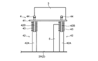
押し付け部4は、電気部品3が配置され、当該電気部品3を蓋6(図3参照)に向けて押し付ける部分である。図2に示すように、押し付け部4は、台座41と、支持部材42と、付勢部材43と、規制部材44とを有する。
台座41は、電気部品3が載せられる部分であり、矩形の板状に構成されている。支持部材42は、台座41を支持する部分であり、台座41の4角にそれぞれ配置される。
支持部材42は、第1軸42Aと、第2軸42Bとを有する。第1軸42Aは、筐体2の底部2Aから立ち上がった部分である。第2軸42Bは、第1軸42Aの上端から延びており、第1軸42Aよりも径が小さい。第2軸42Bには、台座41が通される。これにより、支持部材42は、台座41を移動可能に支持している。
付勢部材43は、台座41を蓋6に向けて付勢するための圧縮バネである。付勢部材43は、台座41と第1軸42Aとの間に位置するように第2軸42Bに通されている。これにより、付勢部材43は、図示上方向に台座41を付勢する。
規制部材44は、第2軸42Bの上端部に配置されるキャップであり、台座41が支持部材42から脱落することを規制する。
送風部5は、筐体2内に風を送ることで筐体2内の熱を拡散するためのファンであり、筐体2内における台座41の下方に配置されている。
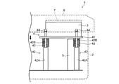
図3に示すように、蓋6は、筐体2と同様の材料で構成された蓋であり、筐体2側を向く裏面に放熱部材7を有している。蓋6は、本発明の「放熱部」に対応する。
放熱部材7は、熱伝導性を有する材料から構成された、弾性の放熱シートである。放熱部材7は、蓋6において、電気部品3の全範囲をカバーできるような範囲に位置している。
また、電気部品3は、押し付け部4の台座41に載せられると、筐体2の側壁よりも突出した位置に、上面が位置する。そのため、蓋6により筐体2を閉じようとすると、電気部品3が蓋6に押されることにより、付勢部材43の付勢力に抗して下側に下げられる。
言い換えると、押し付け部4は、蓋6で筐体2を密閉することに連動して電気部品3を蓋6に向けて押し付ける。その結果、電気部品3からの熱が蓋6に伝わるので、蓋6により、外部に電気部品3から伝えられた熱を効率よく放熱することができる。
また、蓋6を閉じるだけで電気部品3を蓋6の放熱部材7に接触させることができるので、蓋6の開閉や電気部品3の配線整理など、組み立て、設置の作業性を向上させることができる。
また、蓋6の電気部品3が押し付けられる位置に放熱部材7が位置しているため、放熱部材7が電気部品3に接触することで弾性変形することにより、電気部品3の上面全体を放熱部材7に満遍なく接触させることができる。そのため、電気部品3からの熱をさらに効率よく放熱部材7を介して蓋6に伝えることできる。
ところで、筐体2が大型である場合、公差管理がラフであり、発熱体に相当する部品の寸法に応じて放熱部材7の潰れ量を管理する必要が生じる。しかし、本実施の形態では、電気部品3が蓋6に向けて押し付けられるので、電気部品3が接触することによる放熱部材7の潰れ量を容易に管理することができるとともに、容易に電気部品3を放熱部材7に接触させることができる。
また、防爆性能を有する筐体2の場合、筐体2内部の部品の変更によっては、防爆の認証を再取得する必要があるため、筐体2内部の部品が変更された際にも、部品変更を最小限になるように考慮する必要がある。
しかし、本実施の形態では、付勢部材43の付勢力により電気部品3を蓋6に押し付けるため、電気部品3が変わるような場合においても、その他の部品を変更することなく、又は、必用最低限の部品の交換のみで、電気部品3を蓋6に押し付けることができる。そのため、防爆性能を有する筐体2において、筐体2内部の部品が変更された際にも、部品変更を最小限に止めることができる。
また、送風部5が筐体2内に配置されているので、筐体2内の熱を拡散でき、ひいては筐体2全体の熱を効率よく放熱することができる。また、送風部5により電気部品3以外の発熱体を冷却することができる。
なお、上記実施の形態では、送風部5が筐体2の台座41の下方に設けられていたが、本発明はこれに限定されず、例えば、電気部品3に送風部5からの風が当たるような位置に送風部5を配置しても良い。
その他、上記実施の形態は、何れも本発明を実施するにあたっての具体化の一例を示したものに過ぎず、これらによって本発明の技術的範囲が限定的に解釈されてはならないものである。すなわち、本発明はその要旨、またはその主要な特徴から逸脱することなく、様々な形で実施することができる。
2017年1月5日出願の特願2017-000476の日本出願に含まれる明細書、図面および要約書の開示内容は、すべて本願に援用される。
1 放熱装置
2 筐体
3 電気部品
4 押し付け部
5 送風部
6 蓋
7 放熱部材
41 台座
42 支持部材
42A 第1軸
42B 第2軸
43 付勢部材
44 規制部材
2 筐体
3 電気部品
4 押し付け部
5 送風部
6 蓋
7 放熱部材
41 台座
42 支持部材
42A 第1軸
42B 第2軸
43 付勢部材
44 規制部材
Claims (6)
- 密閉可能な筐体と、
前記筐体内に配置され、発熱する発熱体と、
密閉された前記筐体内で前記発熱体の熱を放熱する放熱部と、
前記放熱部に向けて前記発熱体を押し付ける押し付け部と、
を備える放熱装置。 - 前記放熱部は、前記筐体を密閉する蓋であり、
前記押し付け部は、前記蓋で前記筐体を密閉することに連動して前記発熱体を前記放熱部に向けて押し付ける、
請求項1に記載の放熱装置。 - 前記蓋には、前記発熱体が押し付けられる位置に放熱部材が設けられている、
請求項2に記載の放熱装置。 - 前記押し付け部は、
前記発熱体が載せられる台座と、
前記台座を移動可能に支持する支持部材と、
前記台座を前記放熱部に向けて付勢する付勢部材と、
を有する、
請求項1~3の何れか1項に記載の放熱装置。 - 前記押し付け部は、前記台座が前記支持部材から脱落することを規制する規制部材を有する、
請求項4に記載の放熱装置。 - 前記筐体内に配置され、当該筐体内に風を送る送風部を備える、
請求項1~5の何れか1項に記載の放熱装置。
Applications Claiming Priority (2)
| Application Number | Priority Date | Filing Date | Title |
|---|---|---|---|
| JP2017-000476 | 2017-01-05 | ||
| JP2017000476 | 2017-01-05 |
Publications (1)
| Publication Number | Publication Date |
|---|---|
| WO2018128052A1 true WO2018128052A1 (ja) | 2018-07-12 |
Family
ID=62789513
Family Applications (1)
| Application Number | Title | Priority Date | Filing Date |
|---|---|---|---|
| PCT/JP2017/044337 Ceased WO2018128052A1 (ja) | 2017-01-05 | 2017-12-11 | 放熱装置 |
Country Status (1)
| Country | Link |
|---|---|
| WO (1) | WO2018128052A1 (ja) |
Citations (3)
| Publication number | Priority date | Publication date | Assignee | Title |
|---|---|---|---|---|
| JPS5892792U (ja) * | 1981-12-15 | 1983-06-23 | 横河電機株式会社 | 電子装置 |
| JPH0432300A (ja) * | 1990-05-29 | 1992-02-04 | Fuji Electric Co Ltd | 電子機器の冷却装置 |
| JPH0722593U (ja) * | 1993-09-24 | 1995-04-21 | 株式会社チノー | 電子機器 |
-
2017
- 2017-12-11 WO PCT/JP2017/044337 patent/WO2018128052A1/ja not_active Ceased
Patent Citations (3)
| Publication number | Priority date | Publication date | Assignee | Title |
|---|---|---|---|---|
| JPS5892792U (ja) * | 1981-12-15 | 1983-06-23 | 横河電機株式会社 | 電子装置 |
| JPH0432300A (ja) * | 1990-05-29 | 1992-02-04 | Fuji Electric Co Ltd | 電子機器の冷却装置 |
| JPH0722593U (ja) * | 1993-09-24 | 1995-04-21 | 株式会社チノー | 電子機器 |
Similar Documents
| Publication | Publication Date | Title |
|---|---|---|
| JP2009182182A (ja) | 電子部品収容ケース体における放熱構造 | |
| JP6885194B2 (ja) | 電子機器 | |
| JP2009194203A (ja) | 電子機器 | |
| WO2017026128A1 (ja) | モータ装置 | |
| TW201430533A (zh) | 散熱模組 | |
| JP6303981B2 (ja) | 電気機器 | |
| JP2010226858A (ja) | 制御盤装置 | |
| JP5473261B2 (ja) | 撮像装置 | |
| WO2018128052A1 (ja) | 放熱装置 | |
| CN103081100B (zh) | 冷却装置、印制基板单元以及电子装置 | |
| JP2014116335A (ja) | 携帯型電子機器 | |
| JP6026063B1 (ja) | モータ装置 | |
| JP6408217B2 (ja) | 圧縮機用電子回路装置 | |
| JP4845914B2 (ja) | 電子機器の冷却構造 | |
| JP2001332881A (ja) | 電子機器 | |
| JPH04188796A (ja) | 制御装置 | |
| JP2022010604A (ja) | 電子機器 | |
| TW201400785A (zh) | 電子設備及其散熱裝置 | |
| JP2006049388A (ja) | 電子機器および冷却構造 | |
| CN210900156U (zh) | 调速电机控制器 | |
| JP2005300092A (ja) | 冷蔵庫制御基板の収納装置 | |
| JP2012018683A (ja) | 電子機器 | |
| JP2013120912A (ja) | 電子部品ユニット及び電子部品ユニットの放熱方法 | |
| JP2005019743A (ja) | 電気機器の放熱取付構造 | |
| JP2008047798A (ja) | 電子機器 |
Legal Events
| Date | Code | Title | Description |
|---|---|---|---|
| 121 | Ep: the epo has been informed by wipo that ep was designated in this application |
Ref document number: 17890269 Country of ref document: EP Kind code of ref document: A1 |
|
| NENP | Non-entry into the national phase |
Ref country code: DE |
|
| 122 | Ep: pct application non-entry in european phase |
Ref document number: 17890269 Country of ref document: EP Kind code of ref document: A1 |
|
| NENP | Non-entry into the national phase |
Ref country code: JP |