WO2018123364A1 - ペダル装置 - Google Patents
ペダル装置 Download PDFInfo
- Publication number
- WO2018123364A1 WO2018123364A1 PCT/JP2017/041988 JP2017041988W WO2018123364A1 WO 2018123364 A1 WO2018123364 A1 WO 2018123364A1 JP 2017041988 W JP2017041988 W JP 2017041988W WO 2018123364 A1 WO2018123364 A1 WO 2018123364A1
- Authority
- WO
- WIPO (PCT)
- Prior art keywords
- pedal
- arm
- pedal arm
- electric motor
- generating unit
- Prior art date
- Legal status (The legal status is an assumption and is not a legal conclusion. Google has not performed a legal analysis and makes no representation as to the accuracy of the status listed.)
- Ceased
Links
Images












Classifications
-
- B—PERFORMING OPERATIONS; TRANSPORTING
- B60—VEHICLES IN GENERAL
- B60K—ARRANGEMENT OR MOUNTING OF PROPULSION UNITS OR OF TRANSMISSIONS IN VEHICLES; ARRANGEMENT OR MOUNTING OF PLURAL DIVERSE PRIME-MOVERS IN VEHICLES; AUXILIARY DRIVES FOR VEHICLES; INSTRUMENTATION OR DASHBOARDS FOR VEHICLES; ARRANGEMENTS IN CONNECTION WITH COOLING, AIR INTAKE, GAS EXHAUST OR FUEL SUPPLY OF PROPULSION UNITS IN VEHICLES
- B60K26/00—Arrangement or mounting of propulsion-unit control devices in vehicles
- B60K26/02—Arrangement or mounting of propulsion-unit control devices in vehicles of initiating means or elements
-
- G—PHYSICS
- G05—CONTROLLING; REGULATING
- G05G—CONTROL DEVICES OR SYSTEMS INSOFAR AS CHARACTERISED BY MECHANICAL FEATURES ONLY
- G05G1/00—Controlling members, e.g. knobs or handles; Assemblies or arrangements thereof; Indicating position of controlling members
- G05G1/30—Controlling members actuated by foot
-
- G—PHYSICS
- G05—CONTROLLING; REGULATING
- G05G—CONTROL DEVICES OR SYSTEMS INSOFAR AS CHARACTERISED BY MECHANICAL FEATURES ONLY
- G05G5/00—Means for preventing, limiting or returning the movements of parts of a control mechanism, e.g. locking controlling member
- G05G5/03—Means for enhancing the operator's awareness of arrival of the controlling member at a command or datum position; Providing feel, e.g. means for creating a counterforce
Definitions
- the present invention relates to a pedal device that is operated by a pedaling force of an operator, and more particularly to a pedal device that is applied to a vehicle or the like and has a function of generating a vibration for transmitting a vibration to a driver to call attention.
- an accelerator pedal device mounted on an automobile or the like an arm member that is rotatably supported by the vehicle body, a pedal plate that is attached to the tip of the arm member and is operated by a driver's pedal force, and is attached to the arm member on the back side of the pedal plate
- electric motors a contact portion provided on the back side of the pedal plate so that the rotor of the electric motor abuts intermittently, a lead wire wired along the arm member, etc.
- accelerator pedal devices include an arm member that is rotatably supported by the vehicle body, a pedal plate that is attached to the tip of the arm member and is operated by the driver's pedaling force, and for transmitting vibrations to the driver via the pedal plate.
- an actuator including an actuator that generates the above vibration, an arm member made hollow, and an actuator and a lead wire disposed inside the arm member (see Patent Document 2).
- the arm member needs to be hollow, and a heavy object is attached to the back side of the pedal plate. Furthermore, when the shape of the pedal plate and the arm member differs depending on the vehicle type, it is necessary to attach the actuator corresponding to each arm member.
- This invention is providing the pedal apparatus which can eliminate the above problems of the prior art while simplifying the structure.
- the pedal device of the present invention includes a pedal arm having an operation pedal, a support base that supports the pedal arm so as to be swingable about a predetermined swing axis, and a vibration generating unit that generates vibration, In the vicinity of the swing axis, the pedal arm is attached.
- the vibration generating unit may include a configuration including an electric motor having an eccentric mass body on the rotation shaft.
- the vibration generating unit may include a case that accommodates the electric motor and is fixed to the pedal arm, and a connector that protrudes from the case to electrically connect the electric motor.
- the case includes a case body that defines an opening that opens downward or obliquely downward in the vertical direction and that houses the electric motor, and a case cover that is coupled to the case body so as to close the opening.
- a configuration may be adopted.
- the pedal arm may include a receiving recess formed to receive and fix the electric motor and a connector protruding from the vicinity of the receiving recess to electrically connect the electric motor. Good.
- the accommodation recess is formed so as to define an opening that opens on the back side opposite to the front side where the operation pedal is provided, and the pedal arm is connected so as to close the opening of the accommodation recess.
- a configuration including a cover may be adopted.
- a configuration may be adopted in which the connector is arranged to extend toward the swing axis within the swing range of the pedal arm.
- the electric motor may be configured to be fixed to the case or the housing recess through an elastic member.
- a configuration may be adopted in which the rotating shaft of the electric motor is oriented so as to extend in a direction other than parallel to the swing axis.
- the pedal arm includes a resin portion formed of a resin material and a metal sleeve fitted in the through hole of the resin portion, and the vibration generating unit is pedaled by a bolt passed through the sleeve.
- the case includes a fitting cylinder portion that fits a part of the sleeve and abuts on one side portion of the pedal arm, and a nut fitting portion that non-rotatably positions and fits the nut into which the bolt is screwed.
- a configuration including the above may be adopted.
- the sleeve is set to a dimension shorter than the length dimension from the seat surface of the nut in the nut fitting portion to the seat surface of the bolt in the pedal arm, while one end portion of the sleeve can contact the nut.
- a configuration may be adopted.
- the pedal arm includes a metal part formed of a metal material and a through-hole formed in the metal part, and the vibration generating unit is configured of a metal part of the pedal arm by a bolt passed through the through-hole.
- the pedal arm includes a supported portion centered on the swing axis, an upper arm extending upward from the supported portion, and a lower arm extending downward from the supported portion,
- a configuration may be adopted in which the unit is attached to the lower arm in the vicinity of the supported portion.
- a pedal device that can solve the problems of the prior art and achieve simplification of the structure, etc., and can alert the operator without affecting the pedal operation can be obtained.
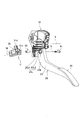
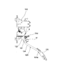
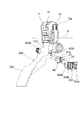
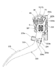
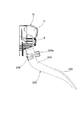
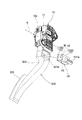
- FIG. 1 illustrates a first embodiment of a pedal device according to the present invention, and is an exploded perspective view in which a state where a vibration generating unit is removed is viewed from the left side.
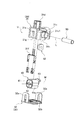
- FIG. 2 is a right side view showing the inside of the housing and the entire pedal arm in the pedal device shown in FIG. 1. It is a disassembled perspective view which shows the vibration generating unit contained in the pedal apparatus shown in FIG. FIG.
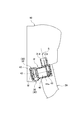
- FIG. 5 is a cross-sectional view showing a state where the vibration generating unit shown in FIG. 4 is attached to the pedal arm in the vicinity of the swing axis. It is a side view which shows the relationship between the rotating shaft of the electric motor contained in the vibration generating unit shown in FIG. 4, and the rocking
- FIG. 2 is a left side view of the pedal device shown in FIG. 1 when a pedal arm to which a vibration generating unit is attached is located at a maximum depression position. 2 is a graph showing vibration characteristics of an operation pedal by a vibration generating unit in the pedal device shown in FIG. 1.
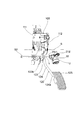
- FIG. 7 is a disassembled perspective view showing a second embodiment of the pedal device according to the present invention, as viewed from the right side obliquely in a state where a vibration generating unit is removed.
- FIG. 7 is a disassembled perspective view showing a second embodiment of the pedal device according to the present invention, as viewed obliquely from the left side in a state where a vibration generating unit is removed. It is a right view which shows the inside of the pedal apparatus shown in FIG. In the pedal apparatus shown in FIG. 10, it is a left view when the pedal arm which attached the vibration generating unit is located in a rest position. In the pedal apparatus shown in FIG. 10, it is a right view when the pedal arm which attached the vibration generating unit is located in a rest position.
- FIG. 10 is a right view which shows the pedal arm which attached the vibration generating unit is located in a rest position.
- FIG. 5 is a disassembled perspective view illustrating a third embodiment of the pedal device according to the present invention, as viewed from the right side obliquely in a state where a vibration generating unit is removed.
- the third embodiment of the pedal device according to the present invention is shown, and is an exploded perspective view in which the state where the vibration generating unit is removed is viewed obliquely from the left side.
- the third embodiment of the pedal device according to the present invention is shown and is an exploded perspective view in which the state where the vibration generating unit is removed is viewed obliquely from the back side.
- FIG. 15 it is the right view which shows the whole pedal arm which attached the inside of the housing, and the vibration generating unit.
- FIG. 15 it is the right view which shows the whole pedal arm which attached the inside of the housing, and the vibration generating unit.
- FIG. 15 is a disassembled perspective view illustrating a fourth embodiment of the pedal device according to the present invention, in which a state where a vibration generating unit is removed is viewed obliquely from the back side.
- the inside of a housing and the right side view which shows the whole pedal arm which attached the vibration excitation unit are shown.
- FIG. 22 is a left side view of the pedal device shown in FIG. 21 when the pedal arm to which the vibration generating unit is attached is located at a rest position.
- the pedal device according to the first embodiment is an accelerator pedal device mounted on an automobile or the like. As shown in FIGS. 1 to 8, the housing 10, the pedal arm 20, and the case 30 as a support base fixed to the vehicle body. And the vibration unit U including the electric motor 40, the sleeve 50, the bolt 61 and the nut 62, the slider 70, the urging spring 80, the return spring 90, and a position sensor for detecting the rotational angle position of the pedal arm 20.
- the position sensor includes an armature and a yoke embedded in the pedal arm 20, a stator and a hall element embedded in the housing 10.
- the housing 10 is made of a resin material, and includes a first housing 11 and a second housing 12 that are coupled to each other to define the swing axis S.
- the first housing 11 accommodates the slider 70, the urging spring 80, and the return spring 90 in the state where the pedal arm 20 is incorporated so as to be swingable about the swing axis S.
- the second housing 12 includes a connector 12a that electrically connects a hall element of a built-in position sensor.
- the second housing 12 excludes the lower region of the pedal arm 20 in cooperation with the first housing 11 in a state where the pedal arm 20, the slider 70, the biasing spring 80, and the return spring 90 are mounted on the first housing 11.
- the first housing 11 is connected to the first housing 11 by a snap-fit connection so as to cover the whole, and is fastened with screws.
- the pedal arm 20 is entirely formed of a resin material and functions as a resin part.
- the pedal arm 20 includes a cylindrical portion 21 as a supported portion, an upper arm 22 extending upward from the cylindrical portion 21, and a cylindrical portion 21.
- a lower arm 23 extending downward and an accelerator pedal 24 as an operation pedal are provided.
- the accelerator pedal 24 is integrally formed with the pedal arm 20.
- the upper side and the lower side indicate the upper side and the lower side in the vertical direction when the accelerator pedal device is mounted on a vehicle or the like.
- the cylindrical portion 21 is supported by the support portion of the housing 10 so as to be swingable about the swing axis S.
- the upper arm 22 includes a contact portion 22 a that contacts the inner wall of the housing 10 at the rest position, a contact portion 22 b that removably contacts the slider 70, and a spring receiving portion 22 c that receives the end of the return spring 90.
- the lower arm 23 has, in the vicinity of the cylindrical portion 21, a contact portion 23 a that contacts the housing 10 at the maximum depression position, and a cylindrical through hole 23 b centering on an axis L parallel to the swing axis S.
- the through hole 23b is formed so as to extend in the direction of the axis L in a region exposed to the outside when the pedal arm 20 is incorporated in the housing 10.
- the lower arm 23 has, at both ends of the through hole 23b, one side portion 23c with which the case 30 of the vibration generating unit U is in contact and the other side portion 23d with which the head of the bolt 61 is in contact.
- the one side portion 23c is formed in a concave shape so that the inner wall surface 23c1 having two parallel surfaces with which the fitting cylinder portion 31c of the case 30 is non-rotatably fitted and the front end surface 31c1 of the fitting cylinder portion 31c are abutted. It has an annular contact surface 23c2 in contact therewith.
- the other side portion 23d protrudes in an annular shape in the direction of the axis L around the through hole 23b, and forms a seat surface on which the head of the bolt 61 abuts.
- the vibration generating unit U includes a case 30 and an electric motor 40.
- the case 30 is made of a resin material, and includes a case main body 31 and a case cover 32 that is detachably connected to the case main body 31.
- the case body 31 includes a concave portion 31a, a nut fitting portion 31b, a fitting tube portion 31c, a connector 31d, a snap fitting convex portion 31e, an incorporated terminal 31f, and openings 31g and 31h.
- the concave portion 31a is formed so as to accommodate the electric motor 40, and is formed so as to define an opening portion 31g that opens downward in the vertical direction or obliquely downward when attached to the pedal arm 20.
- the nut fitting part 31b defines an opening part 31h adjacent to the opening part 31g, and is formed so as to position and fit the nut 62 so as not to rotate. Moreover, the nut fitting part 31b forms the seat surface with which the nut 62 contact
- the fitting cylinder part 31c is formed in a cylindrical shape having two parallel surfaces, and a part of the sleeve 50 is fitted inside the fitting cylinder part 31c, and the fitting cylinder part 31c is fitted to the concave one side part 23c of the pedal arm 20. It is formed to touch. That is, the vibration generating unit U is positioned at a predetermined angular position around the axis L with respect to the pedal arm 20 by fitting the outer peripheral wall of the fitting cylinder portion 31c to the inner wall surface 23c1 of the one side portion 23c. .
- the tip end surface 31c1 of the fitting cylinder portion 31c is brought into contact with the annular contact surface 23c2 of the one side portion 23c, so that the vibration generating unit U is positioned at a predetermined position in the axis L direction with respect to the pedal arm 20. It is done.
- the connector 31d accommodates a terminal 31f for electrical connection, and is always on the axis S in the swing range (rest position to maximum depressed position) of the pedal arm 20 with the vibration generating unit U fixed to the pedal arm 20. It arrange
- the connector 31d since the connector 31d is always directed toward the axis S when the pedal arm 20 moves between the rest position and the maximum depression position, the displacement amount of the wiring on the vehicle body side can be reduced. Therefore, it is possible to prevent interference or wear with other parts accompanying the movement of the wiring, disconnection, or the like.
- the case cover 32 includes a snap-fit concave portion 32 a and a rectangular annular fitting portion 32 b that fits into the concave portion 31 a of the case main body 31.
- the case cover 32 is connected to the case main body 31 so as to close the openings 31g and 31h of the case main body 31 by snap-fit coupling in a state where the electric motor 40 and the nut 62 are accommodated in the case main body 31. .
- the electric motor 40 includes a motor main body 41 to which an elastic member 41 a is attached, a rotating shaft 42 having an axis M, and an eccentric mass body 43 fixed to the rotating shaft 42.
- the elastic member 41 a is formed in a cylindrical shape from an elastic material such as silicone rubber having a predetermined thickness, and is mounted so as to surround the outer periphery of the motor body 41.
- the electric motor 40 is fixed in the case 30 while compressing the elastic member 41a from all directions by the motor body 41 being fitted into the recess 31a of the case body 31 and being closed while being pressed by the case cover 32. .
- the eccentric mass body 43 rotates integrally with the rotating shaft 42 to generate vibration. The generated vibration is transmitted to the pedal arm 20 and the accelerator pedal 24 through the case 30.
- the electric motor 40 is held in the case 30 via the elastic member 41a, it is possible to prevent or suppress the occurrence of a gap between the electric motor 40 and the case 30 due to a change over time. . Therefore, vibration generated by the electric motor 40 can be efficiently transmitted from the case 30 to the pedal arm 20 without disappearing as sound energy such as rattling.
- the rotation shaft 42 (axis M) of the electric motor 40 is oriented so as to extend in a direction other than parallel to the swing axis S. . That is, the rotating shaft 42 of the electric motor 40 is arranged in a direction twisted with the swing axis S of the pedal arm 20 so that the vibration direction of the eccentric mass body 43 does not coincide with the swing direction of the pedal arm 20. become. Thereby, it is possible to prevent an adverse effect on the operation of the pedal arm 20, and it is possible to ensure the desired operability while alerting the user with a vibration generated in a direction that does not coincide with the swinging direction.
- the sleeve 50 is formed in a cylindrical shape from a metal material, and a bolt 61 is passed through the inside thereof. Similarly, the bolt 61 and the nut 62 are made of metal.
- the sleeve 50 is fitted so as to be inserted through the through hole 23 b of the pedal arm 20 and the fitting cylinder portion 31 c of the case 30, and is incorporated so that the one end portion 51 can come into contact with the nut 62.
- the pedal arm 20 is formed of a resin material, and the metal sleeve 50 is fitted into the through hole 23b extending in parallel with the swing axis S, and the vibration unit U is passed through the sleeve 50. Fastened by 61. Accordingly, the weight and formability of the pedal arm 20 can be improved, and the vibration generating unit U can be firmly fixed to the pedal arm 20, so that the vibration generated by the electric motor 40 can be reliably transmitted to the pedal arm 20. Can be transmitted.
- the sleeve 50 has a predetermined amount than the length W from the seat surface of the nut 62 in the nut fitting portion 31 b to the seat surface (the other side portion 23 d) of the bolt 61 in the pedal arm 20.
- the dimension is set to a short dimension H (H ⁇ W). According to this, the rigidity in the connection region is enhanced by bringing the one end portion 51 of the sleeve 50 into contact with the nut 62 fitted to the nut fitting portion 31 b of the case 30.
- the rigidity in the coupling region is further enhanced. Therefore, the vibration generated by the vibration generating unit U can be efficiently transmitted to the pedal arm 20 without being attenuated in the connection region.
- the case 30 defines the openings 31g and 31h that open downward or obliquely downward in the vertical direction to close the case main body 31 and the openings 31g and 31h that house the electric motor 40. Since the case cover 32 connected to the main body 31 is included, when the pedal device is mounted on a vehicle or the like, the electric motor 40 is covered by the case cover 32 while being inserted into the case main body 31 from the lower side in the vertical direction. It will be. Therefore, even if the operator or the like overflows with a liquid such as drinking water, the liquid can be prevented from entering the case 30 and the intended function can be ensured.
- the slider 70 is made of a highly slidable material such as oil-impregnated polyacetal, and is slidably disposed on the inner wall of the housing 10.
- the biasing spring 80 is a compression type coil spring, and is arranged in a compressed state between the inner wall of the housing 10 and the slider 70.
- the slider 70, the contact portion 22 b of the pedal arm 20, and the biasing spring 80 constitute a hysteresis generating mechanism that generates hysteresis in the pedaling force.
- the return spring 90 is a compression type coil spring and is disposed in a compressed state between the inner wall of the housing 10 and the spring receiving portion 22 c of the pedal arm 20.
- the return spring 90 directly applies a biasing force to the pedal arm 20 so as to return the pedal arm 20 to the rest position.
- the vibration generating unit U is exposed from the housing 10 in the region of the lower arm 23 continuous to the lower side of the cylindrical portion 21 with the swing axis S as the center, and in the housing 10. It is attached to the pedal arm 20 in the region of the adjacent lower arm 23. That is, since the vibration generating unit U is attached to the pedal arm 20 in the vicinity of the swing axis S, a long wiring as in the related art becomes unnecessary. Further, there is no operational discomfort that is a concern when the electric motor is provided behind the accelerator pedal as in the prior art. Accordingly, desired operability can be ensured while providing a function of alerting by vibration.
- the vibration generating unit U accommodates the electric motor 40 having the eccentric mass body 43 provided on the rotating shaft 42, the case 30 fixed to the pedal arm 20, and the electric motor 40. Since the connector 31d that protrudes from the case 30 is included as much as possible, the pedal device incorporating the vibration generating unit U can be easily provided by fixing the case 30 housing the electric motor 40 to the pedal arm 20.
- the vibration generating unit U can be modularized and applied to various pedal devices.
- the specification of the pedal arm 20 is different for each vehicle type, by changing only the pedal arm 20, parts such as the housing 10 and the vibration generating unit U can be shared, and cost reduction can be achieved.
- the vibration generating unit U is attached to the lower arm 23 in the vicinity of the cylindrical portion 21 of the pedal arm 20, the moment of inertia of the pedal arm 20 around the swing axis S can be kept small. Thereby, the alerting function by desired vibration can be ensured while ensuring the operability of the pedal arm 20.
- the operation of the accelerator pedal device will be described with reference to FIGS.
- the pedal arm 20 is stopped at the rest position as shown in FIG. 7 by the biasing force of the return spring 90 and the bias spring 80.
- the connector 31d of the vibration generating unit U extends so as to face the direction of the swing axis S.
- the pedal arm 20 rotates clockwise against the urging force of the return spring 90 and the urging spring 80, and as shown in FIG. Rotate to stop.
- the connector 31d of the vibration generating unit U extends so as to face the direction of the swing axis S.
- the connector 31d is disposed so as to extend toward the swing axis S in the swing range (rest position to maximum depressed position) of the pedal arm 20, wiring on the vehicle body side is connected to the connector 31d. Even if the pedal arm 20 swings in the state where it is in this state, the amount of displacement of the wiring can be reduced. Therefore, it is possible to prevent interference or wear with other parts accompanying the movement of the wiring, disconnection, or the like.
- the electric motor 40 of the vibration generating unit U is rotated by a predetermined control signal to generate vibration.
- the generated vibration is transmitted from the case 30 to the pedal arm 20 and the accelerator pedal 24. By transmitting this vibration, the driver is alerted to perform an operation of returning the accelerator pedal 24.
- the vibration generating unit U is attached to the pedal arm 20 in the vicinity of the swing axis S, an operation which is a concern when provided on the back side of the accelerator pedal as in the related art.
- the above feeling of incongruity does not occur, and desired operability can be ensured while providing a function of alerting by vibration.
- the rotating shaft 42 of the electric motor 40 included in the vibration generating unit U is oriented in a direction other than parallel to the swing axis S.
- the axis M is positioned at a right angle with respect to the swing axis S at a twisted position. According to this arrangement, as shown in FIG. 9, the vibration increases in the left-right direction of the accelerator pedal device (in the swing axis S direction), while the vibration decreases in the swing direction of the pedal arm 20.
- the rotating shaft 42 of the electric motor 40 is oriented in the direction twisted with the swing axis S of the pedal arm 20, so that the vibration direction by the eccentric mass body 43 does not coincide with the swing direction of the pedal arm 20. Become. Thereby, it is possible to prevent the operation of the pedal arm 20 from being adversely affected. As a result, desired operability is ensured, and the driver is alerted by vibrations that occur in a direction that does not coincide with the swing direction.
- the pedal device is an accelerator pedal device mounted on an automobile or the like, and includes a vibration generating unit U including a housing 100 as a support base fixed to a vehicle body, a pedal arm 120, a case 30, and an electric motor 40. , Bolts 161 and nuts 62, sliders 171 and 172, biasing springs 181 and 182, a return spring 190, and a position sensor for detecting the rotational angle position of the pedal arm 120.
- the housing 100 is made of a resin material, and includes a first housing 111 and a second housing 112 that are connected to each other to define the swing axis S.
- the first housing 111 accommodates the sliders 171, 172, the urging springs 181, 182, and the return spring 190 in the state where the pedal arm 120 is incorporated so as to be swingable about the swing axis S. It has become.
- the second housing 112 includes a connector 112a that electrically connects a hall element of a built-in position sensor.
- the second housing 112 cooperates with the first housing 111 in a state where the pedal arm 120, the sliders 171 and 172, the biasing springs 181 and 182, and the return spring 190 are mounted on the first housing 111. It is connected to the first housing 111 by a snap fit connection so as to cover the whole except for the lower region, and is fastened with screws.
- the pedal arm 120 is entirely formed of a metal material and functions entirely as a metal part.
- the pedal arm 120 is a thin plate-like disk portion 121 as a supported portion, and a thin plate-like shape extending upward from the disk portion 121.
- An upper arm 122, a thin plate portion 123 as a lower arm extending downward from the disc portion 121, and a rod portion 124 are provided.
- the pedal arm 120 is attached with an accelerator pedal 125 as an operation pedal formed of a resin and a rubber material at an attachment portion 124 a of the rod portion 124.
- the upper side and the lower side indicate the upper side and the lower side in the vertical direction when the accelerator pedal device is mounted on a vehicle or the like.
- the disc portion 121 is engaged with a bearing hole that is a support portion of the housing 100 and is engaged with the shaft portion 121a that is supported so as to be swingable around the swing axis S and the one end portion 191 of the return spring 190.
- the upper arm 122 has an abutment pin 122 a that abuts against a stopper 111 a provided on the inner wall of the housing 100 at the rest position and abuts against an abutment portion 171 b of the slider 171.
- the thin plate portion 123 is formed continuously with the disc portion 121, and has a contact portion 123a that contacts the stopper 111b of the housing 100 at the maximum depression position, and a through-hole centering on an axis L parallel to the swing axis S. 123b.
- the through-hole 123 b is formed in a circular hole centered on the axis L, and is exposed to the outside in a state where the pedal arm 120 is incorporated in the housing 100 and is positioned in the vicinity of the housing 100.
- the rod portion 124 is coupled to the thin plate portion 123 by welding or the like, and has a mounting portion 124a to which the accelerator pedal 125 is attached in the lower end region thereof.
- the vibration generating unit U is the same as that of the first embodiment described above, and includes a case 30 and an electric motor 40.
- a nut 62 is incorporated in the case 30.
- the vibration generating unit U is brought into contact with the right side surface of the thin plate portion 123 that forms part of the lower arm of the pedal arm 120 at the front end surface 31c1 of the case 30, and passes through the through hole 123b from the left side surface of the thin plate portion 123.
- the bolt 161 is screwed into the nut 62 in the case 30, the bolt 161 is firmly fixed to the pedal arm 120.
- the connector 31d of the vibration generating unit U is oriented in a direction away from the swing axis S as shown in FIGS. Yes.
- This attachment state is an example, and the present invention does not exclude an arrangement in which the connector 31d is oriented in a direction away from the swing axis S.
- the connector 31d can be oriented in a preferred direction by appropriately changing the mounting angle of the vibration generating unit U in a layout that does not cause interference or the like.
- the vibration generating unit U is fixed to the pedal arm 120 so that the connector 31d always extends toward the swing axis S in the swing range of the pedal arm 120. preferable.
- the slider 171 is made of a highly slidable material such as oil-impregnated polyacetal, and has an inclined surface 171 a that contacts the inclined surface 172 b of the slider 172 and an abutting portion 171 b that abuts on the abutting pin 122 a of the pedal arm 120.
- the slider 172 is formed of a highly slidable material such as oil-impregnated polyacetal, and has an inclined surface 172 a that contacts the inclined surface 171 a of the slider 171.
- the sliders 171 and 172 are slidably disposed on the inner wall of the housing 100 with the inclined surfaces 171a and 172a in contact with each other.
- the biasing spring 181 is a compression type coil spring, and is arranged in a compressed state between the inner wall of the housing 100 and the slider 171.
- the biasing spring 182 is a compression type coil spring, and is arranged in a compressed state between the inner wall of the housing 100 and the slider 172.
- the sliders 171 and 172 and the urging springs 181 and 182 constitute a hysteresis generating mechanism that generates hysteresis in the pedaling force.
- the return spring 190 is a torsion coil spring, and around the swing axis S, one end portion 191 is hooked on the hook portion 121b of the pedal arm 120 and the other end portion is hooked on a part of the housing 100. Is arranged in.
- the return spring 190 directly applies a biasing force to the pedal arm 120 so as to return the pedal arm 20 to the rest position.
- the vibration generating unit U is a region of the thin plate portion 123 of the lower arm that continues to the lower side of the disc portion 121 with the swing axis S as the center, and the housing 100. Is attached to the pedal arm 120 in the region of the thin plate portion 123 of the lower arm that is exposed from the housing 100 and close to the housing 100. That is, since the vibration generating unit U is attached to the pedal arm 120 in the vicinity of the swing axis S, a long wiring as in the related art becomes unnecessary. Further, there is no operational discomfort that is a concern when the electric motor is provided behind the accelerator pedal as in the prior art. Accordingly, desired operability can be ensured while providing a function of alerting by vibration.
- the rotating shaft 42 of the electric motor 40 included in the vibration generating unit U is positioned in a direction other than parallel to the swing axis S. That is, the axis M of the rotating shaft 42 is positioned at a right angle with respect to the swing axis S and in a twisted position.
- the rotating shaft 42 of the electric motor 40 is oriented in the direction twisted with the swing axis S of the pedal arm 120, so that the vibration direction of the eccentric mass body 43 does not coincide with the swing direction of the pedal arm 120. Arrangement. Thereby, it is possible to prevent the operation of the pedal arm 120 from being adversely affected. As a result, desired operability is ensured, and the driver is alerted by vibrations that occur in a direction that does not coincide with the swing direction.
- the vibration generating unit U since the vibration generating unit U is directly fixed to the metal thin plate portion 123a as the lower arm, the vibration generating unit U can be pedaled without using the sleeve 50 as shown in the first embodiment.
- the arm 120 can be firmly fixed.
- the case where a part of the lower arm of the pedal arm 120 is formed by the metal rod portion 124 is shown.
- the present invention is not limited to this, and the rod portion 124 is replaced.
- the lower arm may be integrally formed of a thin metal material.
- the case where all the pedal arms 120 were formed with the metal material was shown, it is not limited to this.
- a supported part centering on the swing axis S, an upper arm, and a part of the lower arm continuous to the supported part are formed of a resin material as a resin part, and a part of the lower arm
- a metal rod member fitted to and coupled as a metal part, or a metal plate member as a metal part fastened with a screw to a part of the lower arm may be employed.
- 15 to 20 show a third embodiment of the pedal device according to the present invention.
- the same components as those of the first embodiment are denoted by the same reference numerals, and description thereof is omitted. Further, the operation of the accelerator pedal device is also the same as that of the first embodiment described above, and the description thereof is omitted.
- the pedal device is an accelerator pedal device mounted on an automobile or the like, and includes a housing 10 as a support base fixed to a vehicle body, a pedal arm 220, an electric motor 40 as a vibration generating unit, a slider 70, A bias sensor 80, a return spring 90, and a position sensor that detects the rotational angle position of the pedal arm 220 are provided.
- the pedal arm 220 is entirely formed of a resin material, and includes a cylindrical part 221 as a supported part, an upper arm 222 extending upward from the cylindrical part 221, a lower arm 223 extending downward from the cylindrical part 221, and a lower part.
- a cover 224 detachably connected to the side arm 223 and an accelerator pedal 225 as an operation pedal are provided.
- the accelerator pedal 225 is integrally formed with the pedal arm 220.
- the upper side and the lower side indicate the upper side and the lower side in the vertical direction when the accelerator pedal device is mounted on a vehicle or the like.
- the cylindrical portion 221 is supported by the support portion of the housing 10 so as to be swingable about the swing axis S.
- the upper arm 222 has a contact portion 222 a that contacts the inner wall of the housing 10 in the rest position, a contact portion 222 b that removably contacts the slider 70, and a spring receiving portion 222 c that receives the end of the return spring 90.
- the lower arm 223 includes a contact portion 223a that contacts the housing 10 at the maximum depression position, an accommodation recess 223b, an opening 223c defined by the accommodation recess 223b, a snap fit projection 223d, A connector 223e for electrically connecting the electric motor 40 is provided.
- the housing recess 223b is formed to house and fix the electric motor 40.
- the opening 223c is formed so as to open on the back side opposite to the front side where the accelerator pedal 225 is provided.
- the connector 223e is connected to the wiring on the vehicle body side, and is formed so as to protrude to the front side in the vicinity of the housing recess 223b.
- the cover 224 has a rectangular annular fitting portion 224b that fits into the snap fit recess 224a and the housing recess 223b. And the cover 224 is connected so that the opening part 223c may be obstruct
- the electric motor 40 is fitted into the housing recess 223b of the pedal arm 220 and is closed while being pressed by the cover 224, thereby fixing the elastic member 41a in the housing recess 223b while compressing the elastic member 41a from four directions.
- the eccentric mass body 43 rotates integrally with the rotating shaft 42 to generate vibration.
- the generated vibration is transmitted to the pedal arm 220 and the accelerator pedal 225 via the case 30.
- the electric motor 40 is held in the housing recess 223b via the elastic member 41a, it is possible to prevent or suppress a gap from being generated between the electric motor 40 and the housing recess 223b due to a change over time. Can do. Therefore, the vibration generated by the electric motor 40 can be efficiently transmitted to the pedal arm 220 without disappearing as sound energy such as rattling.
- the rotating shaft 42 (axis M) is oriented so as to extend in parallel with the swing axis S.
- This arrangement is an example, and the present invention does not exclude an arrangement in which the rotating shaft 42 of the electric motor 40 is oriented in parallel with the swing axis S.
- the electric motor 40 can be oriented in a preferred direction by appropriately changing the shape of the housing recess 223b provided in the pedal arm 220.
- the electric motor 40 is preferably fixed to the pedal arm 120 such that the rotating shaft 42 extends in a direction other than parallel to the swing axis S. .
- the connector 223e is disposed so as to protrude to the front side of the pedal arm 220.
- This arrangement is an example, and the present invention does not exclude an arrangement in which the connector 223e is oriented in a direction away from the swing axis S.
- the connector 223e can be oriented in a preferred direction in consideration of the arrangement and shape of the housing recess 223b in a layout that does not cause interference or the like.
- the connector arm 223 is preferably formed on the pedal arm 220 so that the connector 223e always extends toward the swing axis S in the swing range of the pedal arm 220.
- the electric motor 40 as the vibration generating unit is in the region of the lower arm 223 that continues to the lower side of the cylindrical portion 221 centering on the swing axis S and the housing 10. Is attached to the pedal arm 220 in the region of the lower arm 223 that is exposed from the housing 10 and close to the housing 10. That is, since the vibration generating unit is attached to the pedal arm 220 in the vicinity of the swing axis S, a long wiring as in the related art becomes unnecessary. Further, there is no operational discomfort that is a concern when the electric motor is provided behind the accelerator pedal as in the prior art. Accordingly, desired operability can be ensured while providing a function of alerting by vibration.
- the electric motor 40 as the vibration generating unit is built in the pedal arm 220 in the region of the lower arm 23 and in the vicinity of the swing axis S.
- the present invention is not limited to this. It is not something.
- the electric motor 40 may be incorporated at a position that is out of the area of the lower arm 223 and out of the area where the accelerator pedal 225 is arranged.
- the outer contour of the pedal arm 220 can be simplified by disposing the electric motor 40 as a vibration generating unit in the housing recess 223b of the pedal arm 220. Therefore, in the relationship between the accelerator pedal device and the mounting position of the vehicle body, there is no need to consider interference between the vibration generating unit and the vehicle body side components, and the layout of the arrangement becomes easy. Further, the case main body 31, the sleeve 50, the bolt 61, and the nut 62 as shown in the first embodiment are unnecessary. Therefore, the number of parts can be reduced correspondingly, and cost reduction can be achieved.
- 21 to 23 show a fourth embodiment of the pedal device according to the present invention.
- the same components as those of the first embodiment are denoted by the same reference numerals, and the description thereof is omitted. Further, the operation of the accelerator pedal device is also the same as that of the first embodiment described above, and the description thereof is omitted.
- the pedal device is an accelerator pedal device mounted on an automobile or the like, and includes a housing 10 as a support base fixed to the vehicle body, a pedal arm 320, a vibration generating unit U2, a slider 70, and a biasing spring 80.
- a position sensor for detecting the rotational angle position of the return spring 90 and the pedal arm 320 is provided.
- the vibration generating unit U2 includes a case 130 and an electric motor 40. Similar to the first embodiment, the electric motor 40 includes a motor main body 41 to which an elastic member 41 a is attached, a rotating shaft 42, and an eccentric mass body 43 fixed to the rotating shaft 42.
- the case 130 is made of a resin material, and includes a case main body 131 having a connector 131a and a case cover 132 removably connected to the case main body 131, defining a housing recess for housing the electric motor 40. .
- the electric motor 40 is fitted in the housing recess of the case main body 131 and is closed while being pressed by the case cover 132, thereby fixing the elastic member 41 a in the case 130 while compressing the elastic member 41 a from four directions.
- the case 130 has an outer shape that has a substantially rectangular parallelepiped shape, and has an outer dimension that is fitted and fixed to the housing recess 324 of the pedal arm 320 with a predetermined tightening allowance.
- the connector 131a is positioned so as to be positioned on the back side of the pedal arm 320 and to extend in a direction parallel to the swing axis S in a state where the vibration generating unit U2 is attached to the pedal arm 320.
- the pedal arm 320 is entirely formed of a resin material, and includes a cylindrical portion 321 as a supported portion, an upper arm 322 extending upward from the cylindrical portion 321, a lower arm 323 extending downward from the cylindrical portion 321, and operation
- An accelerator pedal 325 as a pedal is provided.
- the accelerator pedal 325 is integrally formed with the pedal arm 320.
- the upper side and the lower side indicate the upper side and the lower side in the vertical direction when the accelerator pedal device is mounted on a vehicle or the like.
- the cylindrical portion 321 is supported by the support portion of the housing 10 so as to be swingable about the swing axis S.
- the upper arm 322 includes a contact portion 322a that contacts the inner wall of the housing 10 at the rest position, a contact portion 322b that removably contacts the slider 70, and a spring receiving portion 322c that receives the end of the return spring 90.
- the lower arm 323 has, in the vicinity of the cylindrical portion 321, an abutting portion 323 a that abuts the housing 10 at the maximum depression position, and an accommodating recess 323 b that fits and fixes the vibration generating unit U ⁇ b> 2.
- the accommodation recess 323b is formed as a substantially rectangular parallelepiped recess while opening on the back side opposite to the front side where the accelerator pedal 325 is provided.
- the accommodation recess 323b is formed in such a size that the case 130 of the vibration generating unit U2 is fitted with a predetermined tightening allowance.
- the vibration unit U2 is firmly fixed to the pedal arm 320 only by fitting the case 130 of the vibration unit U2 into the housing recess 323b.
- the eccentric mass body 43 rotates integrally with the rotating shaft 42 by starting the electric motor 40 in a state where the vibration generating unit U2 is fitted and fixed to the housing recess 323b of the pedal arm 320. This generates vibration. The generated vibration is transmitted to the pedal arm 320 and the accelerator pedal 325 through the case 130.
- the electric motor 40 is held in the case 130 via the elastic member 41a, it is possible to prevent or suppress the occurrence of a gap between the electric motor 40 and the case 130 due to a change over time. Therefore, the vibration generated by the electric motor 40 can be efficiently transmitted from the case 130 to the pedal arm 320 without disappearing as sound energy such as rattling.
- the rotation shaft 42 (axis M) is oriented so as to extend in parallel with the swing axis S.
- This arrangement is an example, and the present invention does not exclude an arrangement in which the rotating shaft 42 of the electric motor 40 is oriented in parallel with the swing axis S.
- the rotation shaft 42 of the electric motor 40 can be oriented in a preferred direction by appropriately changing the shape of the housing recess 323b provided in the pedal arm 320.
- the vibration generating unit U2 is fitted to the pedal arm 320 so that the rotation shaft 42 of the electric motor 40 is oriented so as to extend in a direction other than parallel to the swing axis S. It is preferable to fix together.
- the connector 131a is disposed so as to extend in parallel with the swing axis S on the back side of the pedal arm 320.
- This arrangement configuration is an example, and the present invention does not exclude an arrangement in which the connector 131a is oriented in a direction away from the swing axis S.
- the connector 131a can be oriented in a preferred direction in consideration of the arrangement and shape of the housing recess 323b in a layout that does not cause interference or the like.
- the vibration generating unit U2 or the case 130 is formed so that the connector 131a always extends toward the swing axis S in the swing range of the pedal arm 320. Is preferred.
- the vibration generating unit U2 is exposed from the housing 10 in the region of the lower arm 323 that continues to the lower side of the cylindrical portion 321 with the swing axis S as the center. In the region of the lower arm 323 close to the housing 10, it is attached to the pedal arm 320. That is, since the vibration generating unit U2 is attached to the pedal arm 320 in the vicinity of the swing axis S, a long wiring as in the related art becomes unnecessary. Further, there is no operational discomfort that is a concern when the electric motor is provided behind the accelerator pedal as in the prior art. Accordingly, desired operability can be ensured while providing a function of alerting by vibration.
- the outer contour of the pedal arm 320 can be simplified by disposing the vibration generating unit U2 in the housing recess 323b of the pedal arm 320. Therefore, in the relationship between the accelerator pedal device and the mounting position of the vehicle body, it is not necessary to consider interference between the vibration generating unit U2 and the vehicle body side parts, and the layout of the unit becomes easy. Further, since the sleeve 50, the bolt 61, and the nut 62 as shown in the first embodiment are unnecessary, the number of parts can be reduced by that amount.
- the vibration generating unit is attached to the pedal arm in the vicinity of the swing axis S in the region from the swing axis to the lower end of the pedal arm. It is not limited to this.
- the vibration generating unit is attached to the pedal arm at a position deviating from the region where the operation pedal is disposed in the region from the swing axis of the pedal arm to the lower end, that is, in the region between the swing axis and the operation pedal.
- the configuration described above may be adopted.
- the electric motor 40 including the eccentric mass body 43 is included as the vibration generating unit, but the present invention is not limited to this.
- a solenoid type actuator that reciprocates in a predetermined direction, or a vibration generating unit including other vibration sources may be employed.
- the accelerator pedal apparatus mounted in a motor vehicle was shown as a pedal apparatus, it is not limited to this.
- the vibration generating unit according to the present invention may be applied to a brake pedal device including a bracket fixed to a vehicle body as a support base and a brake pedal as an operation pedal.
- the present invention is not limited to a pedal device mounted on an automobile, and may be any other vehicle or a machine having an operation pedal other than a vehicle, as long as it has an operation pedal that is operated by an operator with a pedaling force. May be applied.
- the pedal device of the present invention can call attention to the operator without affecting the pedal operation while solving the problems of the prior art and achieving simplification of the structure and the like. It can be applied to automobiles and the like, and is also useful in other vehicles and other fields.
Landscapes
- Engineering & Computer Science (AREA)
- Physics & Mathematics (AREA)
- General Physics & Mathematics (AREA)
- Automation & Control Theory (AREA)
- Chemical & Material Sciences (AREA)
- Combustion & Propulsion (AREA)
- Transportation (AREA)
- Mechanical Engineering (AREA)
- Mechanical Control Devices (AREA)
- Auxiliary Drives, Propulsion Controls, And Safety Devices (AREA)
Abstract
本発明のペダル装置は、操作ペダルを有するペダルアーム(20)、ペダルアームを所定の揺動軸線(S)回りに揺動自在に支持する支持ベース(10)、振動を発生する起振ユニット(U)を備え、起振ユニット(U)は、揺動軸線(S)の近傍においてペダルアーム(20)に取り付けられている。これによれば、長い配線が不要になり、操作ペダルの操作において違和感を生じることもなく、振動による注意を喚起でき、所望の操作性を確保できる
Description
本発明は、操作者の踏力により操作されるペダル装置に関し、特に、車両等に適用されて運転者に振動を伝えて注意を促すための振動を発生させる機能を備えたペダル装置に関する。
自動車等に搭載のアクセルペダル装置としては、車体に回動可能に支持されたアーム部材、アーム部材の先端に取り付けられ運転者の踏力により操作されるペダルプレート、ペダルプレートの裏側においてアーム部材に取り付けられた電動モータ、電動モータのロータが断続的に当接するべくペダルプレートの裏側に設けられた当接部、アーム部材に沿って配線されたリード線等を備えたものが知られている(特許文献1を参照)。
しかしながら、この装置においては、ペダルプレートの裏側に重量物が取り付けられているため、操作者に違和感を与える虞がある。また、リード線がアーム部材に沿って露出した状態で配線されるため、他の部材と干渉して断線する虞がある。さらに、車種に応じてペダルプレート及びアーム部材が異なる場合、電動モータの取付け構造や当接部を車種ごとに設定する必要がある。
他のアクセルペダル装置としては、車体に回動可能に支持されたアーム部材、アーム部材の先端に取り付けられ運転者の踏力により操作されるペダルプレート、ペダルプレートを介して運転者に振動を伝えるための振動を発生させるアクチュエータを備え、アーム部材を中空とし、アーム部材の内部にアクチュエータ及びリード線を配置したものが知られている(特許文献2を参照)。
しかしながら、この装置においては、アーム部材が中空である必要があり、又、ペダルプレートの裏側に重量物が取り付けられているため、前述同様に、操作者に違和感を与える虞がある。さらに、車種に応じてペダルプレート及びアーム部材の形状等が異なる場合、アクチュエータもアーム部材ごとに対応させて取り付ける必要がある。
本発明は、構造の簡素化等を図りつつ、上記のような従来技術の問題点を解消できるペダル装置を提供することにある。
本発明のペダル装置は、操作ペダルを有するペダルアームと、ペダルアームを所定の揺動軸線回りに揺動自在に支持する支持ベースと、振動を発生する起振ユニットとを備え、起振ユニットは、揺動軸線の近傍において、ペダルアームに取り付けられている、構成となっている。
上記構成において、起振ユニットは、回転軸に偏芯質量体を有する電動モータを含む、構成を採用してもよい。
上記構成において、起振ユニットは、電動モータを収容すると共にペダルアームに固定されるケースと、電動モータを電気的に接続するべくケースから突出するコネクタを含む、構成を採用してもよい。
上記構成において、ケースは、鉛直方向の下向き又は斜め下向きに開口する開口部を画定すると共に電動モータを収容するケース本体と、開口部を閉塞するようにケース本体に連結されるケースカバーを含む、構成を採用してもよい。
上記構成において、ペダルアームは、電動モータを収容して固定するべく形成された収容凹部と、電動モータを電気的に接続するべく収容凹部の近傍から突出するコネクタを含む、構成を採用してもよい。
上記構成において、収容凹部は、操作ペダルが設けられた前面側と反対の背面側において開口する開口部を画定するように形成され、ペダルアームは、収容凹部の開口部を閉塞するように連結されるカバーを含む、構成を採用いてもよい。
上記構成において、コネクタは、ペダルアームの揺動範囲において、揺動軸線に向けて伸長するように配置されている、構成を採用してもよい。
上記構成において、電動モータは、弾性部材を介して、ケース又は収容凹部に固定されている、構成を採用してもよい。
上記構成において、電動モータの回転軸は、揺動軸線と平行以外の方向に伸長するように方向付けられている、構成を採用してもよい。
上記構成において、ペダルアームは、樹脂材料により形成された樹脂製部分と、樹脂製部分の貫通孔に嵌合された金属製のスリーブを含み、起振ユニットは、スリーブに通されたボルトによりペダルアームの樹脂製部分に締結されている、構成を採用してもよい。
上記構成において、ケースは、スリーブの一部を嵌合させると共にペダルアームの一側部に当接する嵌合筒部と、ボルトを捩じ込むナットを回動不能に位置決め嵌合するナット嵌合部を含む、構成を採用してもよい。
上記構成において、スリーブは、その一端部がナットに当接し得ると共に、ナット嵌合部におけるナットの座面からペダルアームにおけるボルトの座面までの長さ寸法よりも短い寸法に設定されている、構成を採用してもよい。
上記構成において、ペダルアームは、金属材料により形成された金属製部分と、金属製部分に形成された貫通孔を含み、起振ユニットは、貫通孔に通されたボルトによりペダルアームの金属製部分に締結されている、構成を採用してもよい。
上記構成において、ペダルアームは、揺動軸線を中心とする被支持部と、被支持部から上方に伸長する上側アームと、被支持部から下方に伸長する下側アームを含み、起振ユニットは、被支持部の近傍において下側アームに取り付けられている、構成を採用してもよい。
上記構成をなすペダル装置によれば、従来技術の問題点を解消して構造の簡素化等を達成でき、ペダル操作に影響を及ぼすことなく操作者に注意を喚起できるペダル装置が得られる。
以下、本発明の実施の形態について、添付図面を参照しつつ説明する。
第1実施形態に係るペダル装置は、自動車等に搭載されるアクセルペダル装置であり、図1ないし図8に示すように、車体に固定される支持ベースとしてのハウジング10、ペダルアーム20、ケース30及び電動モータ40を含む起振ユニットU、スリーブ50、ボルト61及びナット62、スライダ70、付勢バネ80、戻しバネ90、ペダルアーム20の回転角度位置を検出する位置センサを備えている。
第1実施形態に係るペダル装置は、自動車等に搭載されるアクセルペダル装置であり、図1ないし図8に示すように、車体に固定される支持ベースとしてのハウジング10、ペダルアーム20、ケース30及び電動モータ40を含む起振ユニットU、スリーブ50、ボルト61及びナット62、スライダ70、付勢バネ80、戻しバネ90、ペダルアーム20の回転角度位置を検出する位置センサを備えている。
位置センサは、ペダルアーム20に埋設されたアマチャ及びヨーク、ハウジング10に埋設されたステータ及びホール素子により構成されている。
ハウジング10は、樹脂材料により形成されており、互いに連結されて揺動軸線Sを画定する第1ハウジング11及び第2ハウジング12により構成されている。
第1ハウジング11は、ペダルアーム20が揺動軸線S回りに揺動自在に組み込まれた状態で、その内部に、スライダ70、付勢バネ80、戻しバネ90を収容するようになっている。
第2ハウジング12は、内蔵される位置センサのホール素子を電気的に接続するコネクタ12aを備えている。
第2ハウジング12は、内蔵される位置センサのホール素子を電気的に接続するコネクタ12aを備えている。
第2ハウジング12は、ペダルアーム20、スライダ70、付勢バネ80、戻しバネ90が第1ハウジング11に装着された状態で、第1ハウジング11と協働してペダルアーム20の下方領域を除いた全体を覆うように、第1ハウジング11にスナップフィット結合により連結されてネジにより締結される。
ペダルアーム20は、全体が樹脂材料により成形されて全体が樹脂製部分として機能するものであり、被支持部としての円筒部21、円筒部21から上方に伸長する上側アーム22、円筒部21から下方に伸長する下側アーム23、操作ペダルとしてのアクセルペダル24を備えている。
アクセルペダル24は、ペダルアーム20に対して一体成型されている。
ここで、上側及び下側とは、アクセルペダル装置が車両等に搭載された状態において、鉛直方向の上側及び下側を示すものである。
アクセルペダル24は、ペダルアーム20に対して一体成型されている。
ここで、上側及び下側とは、アクセルペダル装置が車両等に搭載された状態において、鉛直方向の上側及び下側を示すものである。
円筒部21は、ハウジング10の支持部により、揺動軸線S回りに揺動自在に支持される。
上側アーム22は、休止位置においてハウジング10の内壁と当接する当接部22a、スライダ70と離脱可能に接触する接触部22b、戻しバネ90の端部を受けるバネ受け部22cを有する。
上側アーム22は、休止位置においてハウジング10の内壁と当接する当接部22a、スライダ70と離脱可能に接触する接触部22b、戻しバネ90の端部を受けるバネ受け部22cを有する。
下側アーム23は、円筒部21の近傍において、最大踏込み位置においてハウジング10と当接する当接部23a、揺動軸線Sと平行な軸線Lを中心とする円筒状の貫通孔23bを有する。
貫通孔23bは、ペダルアーム20がハウジング10に組み込まれた状態で外部に露出する領域において、軸線L方向に伸長するように形成されている。
貫通孔23bは、ペダルアーム20がハウジング10に組み込まれた状態で外部に露出する領域において、軸線L方向に伸長するように形成されている。
また、下側アーム23は、貫通孔23bの両端において、起振ユニットUのケース30が当接させられる一側部23c、ボルト61の頭部が当接する他側部23dを有する。
一側部23cは、凹状に形成されて、ケース30の嵌合筒部31cが回動不能に嵌合される平行な二面をもつ内壁面23c1、嵌合筒部31cの先端面31c1が当接する環状当接面23c2を有する。
他側部23dは、貫通孔23bの周りにおいて、軸線L方向に円環状に突出し、ボルト61の頭部が当接する座面を形成している。
一側部23cは、凹状に形成されて、ケース30の嵌合筒部31cが回動不能に嵌合される平行な二面をもつ内壁面23c1、嵌合筒部31cの先端面31c1が当接する環状当接面23c2を有する。
他側部23dは、貫通孔23bの周りにおいて、軸線L方向に円環状に突出し、ボルト61の頭部が当接する座面を形成している。
起振ユニットUは、ケース30及び電動モータ40により構成されている。
ケース30は、樹脂材料により形成されており、ケース本体31、ケース本体31に着脱自在に連結されるケースカバー32により構成されている。
ケース30は、樹脂材料により形成されており、ケース本体31、ケース本体31に着脱自在に連結されるケースカバー32により構成されている。
ケース本体31は、凹部31a、ナット嵌合部31b、嵌合筒部31c、コネクタ31d、スナップフィット用の凸部31e、組み込まれた端子31f、開口部31g,31hを備えている。
凹部31aは、電動モータ40を収容するように形成され、又、ペダルアーム20に取り付けられた状態において鉛直方向の下向き又は斜め下向きに開口する開口部31gを画定するように形成されている。
ナット嵌合部31bは、開口部31gに隣接する開口部31hを画定すると共に、ナット62を回動不能に位置決めして嵌合するように形成されている。
また、ナット嵌合部31bは、軸線L方向において、ナット62が当接する座面を形成している。
ナット嵌合部31bは、開口部31gに隣接する開口部31hを画定すると共に、ナット62を回動不能に位置決めして嵌合するように形成されている。
また、ナット嵌合部31bは、軸線L方向において、ナット62が当接する座面を形成している。
嵌合筒部31cは、平行な二面をもつ筒状に形成され、その内側にスリーブ50の一部が嵌合されると共に、ペダルアーム20の凹状の一側部23cに嵌合されて当接されるように形成されている。
すなわち、嵌合筒部31cの外周壁が、一側部23cの内壁面23c1に嵌合されることにより、起振ユニットUがペダルアーム20に対して軸線L回りの所定の角度位置に位置付けられる。
また、嵌合筒部31cの先端面31c1が、一側部23cの環状当接面23c2に当接させられることにより、起振ユニットUがペダルアーム20に対して軸線L方向の所定位置に位置付けられる。
すなわち、嵌合筒部31cの外周壁が、一側部23cの内壁面23c1に嵌合されることにより、起振ユニットUがペダルアーム20に対して軸線L回りの所定の角度位置に位置付けられる。
また、嵌合筒部31cの先端面31c1が、一側部23cの環状当接面23c2に当接させられることにより、起振ユニットUがペダルアーム20に対して軸線L方向の所定位置に位置付けられる。
コネクタ31dは、電気接続を行う端子31fを収容し、起振ユニットUがペダルアーム20に固定された状態で、ペダルアーム20の揺動範囲(休止位置~最大踏込み位置)において、常に軸線Sに向けて伸長するように配置されている。
これによれば、ペダル装置が車両等に装着される場合、コネクタ31dに車体側の配線が接続される。ここで、ペダルアーム20が休止位置~最大踏込み位置の間で移動するとき、コネクタ31dが常に軸線Sに向けて方向付けられるため、車体側の配線の変位量を小さくできる。
それ故に、配線の移動に伴う他の部品との干渉又は摩耗、あるいは断線等を防止することができる。
これによれば、ペダル装置が車両等に装着される場合、コネクタ31dに車体側の配線が接続される。ここで、ペダルアーム20が休止位置~最大踏込み位置の間で移動するとき、コネクタ31dが常に軸線Sに向けて方向付けられるため、車体側の配線の変位量を小さくできる。
それ故に、配線の移動に伴う他の部品との干渉又は摩耗、あるいは断線等を防止することができる。
ケースカバー32は、スナップフィット用の凹部32a、ケース本体31の凹部31aに嵌合する矩形環状の嵌合部32bを備えている。
そして、ケースカバー32は、電動モータ40及びナット62がケース本体31に収容された状態で、スナップフィット結合により、ケース本体31の開口部31g,31hを閉塞するようにケース本体31に連結される。
そして、ケースカバー32は、電動モータ40及びナット62がケース本体31に収容された状態で、スナップフィット結合により、ケース本体31の開口部31g,31hを閉塞するようにケース本体31に連結される。
電動モータ40は、弾性部材41aが装着されたモータ本体41、軸線Mをもつ回転軸42、回転軸42に固定された偏芯質量体43を備えている。
弾性部材41aは、所定の厚みをなすシリコーンゴム等の弾性材料により筒状に形成されており、モータ本体41の外周を取り囲むように装着されている。
弾性部材41aは、所定の厚みをなすシリコーンゴム等の弾性材料により筒状に形成されており、モータ本体41の外周を取り囲むように装着されている。
そして、電動モータ40は、モータ本体41がケース本体31の凹部31aに嵌め込まれ、ケースカバー32で押圧しつつ閉塞されることにより、弾性部材41aを四方から圧縮しつつケース30内に固定される。
そして、電動モータ40が起動されることにより、回転軸42と一体的に偏芯質量体43が回転することで振動を発生する。発生した振動は、ケース30を介してペダルアーム20及びアクセルペダル24に伝達される。
そして、電動モータ40が起動されることにより、回転軸42と一体的に偏芯質量体43が回転することで振動を発生する。発生した振動は、ケース30を介してペダルアーム20及びアクセルペダル24に伝達される。
このように、電動モータ40は、弾性部材41aを介してケース30内に保持されるため、経時的な変化により電動モータ40とケース30の間に隙間が生じるのを防止ないし抑制することができる。
したがって、電動モータ40が発生する振動を、ガタツキ等の音エネルギとして消失することなく、ケース30からペダルアーム20に向けて効率良く伝達することができる。
したがって、電動モータ40が発生する振動を、ガタツキ等の音エネルギとして消失することなく、ケース30からペダルアーム20に向けて効率良く伝達することができる。
ここで、起振ユニットUがペダルアーム20に取り付けられた状態で、電動モータ40の回転軸42(軸線M)は、揺動軸線Sと平行以外の方向に伸長するように方向付けられている。
すなわち、電動モータ40の回転軸42が、ペダルアーム20の揺動軸線Sと捻れた方向に配置されることで、偏芯質量体43による振動方向がペダルアーム20の揺動方向と一致しないようになる。
これにより、ペダルアーム20の操作に悪影響が及ぶのを防止でき、揺動方向と一致しない方向において生じる振動で注意喚起を行いつつ、所望の操作性を確保することができる。
すなわち、電動モータ40の回転軸42が、ペダルアーム20の揺動軸線Sと捻れた方向に配置されることで、偏芯質量体43による振動方向がペダルアーム20の揺動方向と一致しないようになる。
これにより、ペダルアーム20の操作に悪影響が及ぶのを防止でき、揺動方向と一致しない方向において生じる振動で注意喚起を行いつつ、所望の操作性を確保することができる。
スリーブ50は、金属材料により円筒状に形成され、その内側にボルト61が通されるようになっている。尚、ボルト61及びナット62も同様に金属製である。
ここで、スリーブ50は、ペダルアーム20の貫通孔23b及びケース30の嵌合筒部31cを挿通するように嵌合されて、一端部51がナット62に当接し得るように組み込まれる。
ここで、スリーブ50は、ペダルアーム20の貫通孔23b及びケース30の嵌合筒部31cを挿通するように嵌合されて、一端部51がナット62に当接し得るように組み込まれる。
上記のように、ペダルアーム20が樹脂材料により形成されると共に揺動軸線Sと平行に伸長する貫通孔23bに金属製のスリーブ50が嵌合され、起振ユニットUがスリーブ50に通したボルト61により締結される。
したがって、ペダルアーム20の軽量化及び成型性を高めることができ、又、起振ユニットUをペダルアーム20に堅固に固定することができ、電動モータ40が発生する振動をペダルアーム20に確実に伝達させることができる。
したがって、ペダルアーム20の軽量化及び成型性を高めることができ、又、起振ユニットUをペダルアーム20に堅固に固定することができ、電動モータ40が発生する振動をペダルアーム20に確実に伝達させることができる。
特に、スリーブ50は、図5に示すように、ナット嵌合部31bにおけるナット62の座面からペダルアーム20におけるボルト61の座面(他側部23d)までの長さ寸法Wよりも所定量だけ短い寸法H(H<W)に設定されている。
これによれば、ケース30のナット嵌合部31bに嵌合されたナット62にスリーブ50の一端部51を当接させることで連結領域における剛性が高められる。また、ボルト61の頭部がスリーブ50の他端部52に当接するまで、ペダルアーム20を軸線L方向に圧縮しつつ締め付けることで、連結領域における剛性がさらに高められる。
したがって、起振ユニットUが発生する振動を、連結領域で減衰させることなくペダルアーム20に効率よく伝達することができる。
これによれば、ケース30のナット嵌合部31bに嵌合されたナット62にスリーブ50の一端部51を当接させることで連結領域における剛性が高められる。また、ボルト61の頭部がスリーブ50の他端部52に当接するまで、ペダルアーム20を軸線L方向に圧縮しつつ締め付けることで、連結領域における剛性がさらに高められる。
したがって、起振ユニットUが発生する振動を、連結領域で減衰させることなくペダルアーム20に効率よく伝達することができる。
上記構成においては、スリーブ50の一部をケース30の嵌合筒部31cに嵌合させ、嵌合筒部31cをペダルアーム20の一側部23cに嵌合させつつ当接させ、ペダルアーム20の他側部23dからボルト61をスリーブ50に挿入してナット嵌合部31bに嵌合されたナット62に捩じ込むため、組付け作業を簡単に行えると共に、ケース30とペダルアーム20との連結剛性を高めることができる。
また、上記構成においては、ケース30は、鉛直方向の下向き又は斜め下向きに開口する開口部31g,31hを画定して電動モータ40を収容するケース本体31、開口部31g,31hを閉塞するべくケース本体31に連結されるケースカバー32を含むため、ペダル装置が車両等に搭載された場合に、電動モータ40は鉛直方向の下側からケース本体31内に挿入された状態でケースカバー32により覆われることになる。
したがって、操作者等が仮に飲料水等の液体を溢した場合でも、その液体がケース30内に侵入するのを防止でき、所期の機能を確保することができる。
したがって、操作者等が仮に飲料水等の液体を溢した場合でも、その液体がケース30内に侵入するのを防止でき、所期の機能を確保することができる。
スライダ70は、含油ポリアセタール等の高摺動性材料により形成され、ハウジング10の内壁を摺動自在に配置されている。
付勢バネ80は、圧縮型のコイルバネであり、ハウジング10の内壁とスライダ70の間に圧縮した状態で配置されている。
そして、スライダ70、ペダルアーム20の接触部22b、付勢バネ80により、踏力においてヒステリシスを発生するヒステリシス発生機構が構成されている。
付勢バネ80は、圧縮型のコイルバネであり、ハウジング10の内壁とスライダ70の間に圧縮した状態で配置されている。
そして、スライダ70、ペダルアーム20の接触部22b、付勢バネ80により、踏力においてヒステリシスを発生するヒステリシス発生機構が構成されている。
戻しバネ90は、圧縮型のコイルバネであり、ハウジング10の内壁とペダルアーム20のバネ受け部22cの間に圧縮した状態で配置されている。
そして、戻しバネ90は、ペダルアーム20を休止位置に戻すように、ペダルアーム20に直接付勢力を及ぼすようになっている。
そして、戻しバネ90は、ペダルアーム20を休止位置に戻すように、ペダルアーム20に直接付勢力を及ぼすようになっている。
上記構成をなすペダル装置によれば、起振ユニットUは、揺動軸線Sを中心とする円筒部21の下側に連続する下側アーム23の領域でかつハウジング10から露出すると共にハウジング10に近接する下側アーム23の領域において、ペダルアーム20に取り付けられている。
すなわち、起振ユニットUは、揺動軸線Sの近傍においてペダルアーム20に取り付けられているため、従来のような長い配線が不要になる。
また、従来のように電動モータがアクセルペダルの裏側に設けられる場合に懸念される操作上の違和感を生じることもない。したがって、振動による注意喚起機能を備えつつ、所望の操作性を確保することができる。
すなわち、起振ユニットUは、揺動軸線Sの近傍においてペダルアーム20に取り付けられているため、従来のような長い配線が不要になる。
また、従来のように電動モータがアクセルペダルの裏側に設けられる場合に懸念される操作上の違和感を生じることもない。したがって、振動による注意喚起機能を備えつつ、所望の操作性を確保することができる。
また、起振ユニットUは、回転軸42に偏芯質量体43が設けられた電動モータ40、電動モータ40を収容すると共にペダルアーム20に固定されるケース30、電動モータ40を電気的に接続するべくケース30から突出するコネクタ31dを含むため、電動モータ40を収容したケース30をペダルアーム20に固定することで、起振ユニットUを組み込んだペダル装置を容易に提供することができる。
特に、起振ユニットUをモジュール化でき、種々のペダル装置に適用することができる。例えば、車種ごとにペダルアーム20の仕様が異なる場合、ペダルアーム20のみ変更することで、ハウジング10、起振ユニットU等の部品を共用することができ、低コスト化等を達成できる。
さらに、起振ユニットUは、ペダルアーム20の円筒部21の近傍において下側アーム23に取り付けられるため、揺動軸線S回りにおけるペダルアーム20の慣性モーメントを小さく抑えることができる。これにより、ペダルアーム20の操作性を確保しつつ、所望の振動による注意喚起機能を確保することができる。
次に、アクセルペダル装置の動作について、図7及び図8を参照しつつ説明する。
先ず、運転者がアクセルペダル24を踏み込まない休止位置にあるとき、戻しバネ90及び付勢バネ80の付勢力により、図7に示すように、ペダルアーム20は休止位置に停止している。
このとき、起振ユニットUのコネクタ31dは、揺動軸線Sの方向を向くように伸長している。
先ず、運転者がアクセルペダル24を踏み込まない休止位置にあるとき、戻しバネ90及び付勢バネ80の付勢力により、図7に示すように、ペダルアーム20は休止位置に停止している。
このとき、起振ユニットUのコネクタ31dは、揺動軸線Sの方向を向くように伸長している。
この状態から、運転者がアクセルペダル24を踏み込むと、ペダルアーム20は、戻しバネ90及び付勢バネ80の付勢力に抗して時計回りに回転し、図8に示すように、最大踏込み位置まで回転して停止する。
このとき、起振ユニットUのコネクタ31dは、揺動軸線Sの方向を向くように伸長している。
このとき、起振ユニットUのコネクタ31dは、揺動軸線Sの方向を向くように伸長している。
すなわち、コネクタ31dは、ペダルアーム20の揺動範囲(休止位置~最大踏込み位置)において、揺動軸線Sに向けて伸長するように配置されているため、コネクタ31dに車体側の配線が接続された状態でペダルアーム20が揺動しても、配線の変位量を小さくできる。それ故に、配線の移動に伴う他の部品との干渉又は摩耗、あるいは断線等を防止することができる。
また、車両側の制御手段により、運転者に注意を促す運転モードであると判断された場合は、所定の制御信号により、起振ユニットUの電動モータ40が回転して振動を発生する。そして、発生した振動は、ケース30からペダルアーム20及びアクセルペダル24に伝達される。
この振動の伝達により、アクセルペダル24を戻す操作を行うように、運転者は注意を喚起される。
この振動の伝達により、アクセルペダル24を戻す操作を行うように、運転者は注意を喚起される。
上記構成をなすアクセルペダル装置によれば、起振ユニットUが揺動軸線Sの近傍においてペダルアーム20に取り付けられているため、従来のようにアクセルペダルの裏側に設けられる場合に懸念される操作上の違和感を生じることはなく、振動による注意喚起機能を備えつつも所望の操作性を確保することができる。
また、起振ユニットUに含まれる電動モータ40の回転軸42が、揺動軸線Sと平行以外の方向に方向付けられている。ここでは、軸線Mが揺動軸線Sに対して直角で捻れの位置に位置付けられている。
この配置構成によれば、図9に示すように、アクセルペダル装置の左右方向(揺動軸線S方向)において振動が大きくなり、一方、ペダルアーム20の揺動方向においては振動が小さくなる。
この配置構成によれば、図9に示すように、アクセルペダル装置の左右方向(揺動軸線S方向)において振動が大きくなり、一方、ペダルアーム20の揺動方向においては振動が小さくなる。
すなわち、電動モータ40の回転軸42がペダルアーム20の揺動軸線Sと捻れた方向に方向付けられることで、偏芯質量体43による振動方向がペダルアーム20の揺動方向と一致しない配置となる。これにより、ペダルアーム20の操作に悪影響が及ぶのを防止できる。
その結果、所望の操作性が確保され、揺動方向と一致しない方向において生じる振動により運転者は注意を喚起される。
その結果、所望の操作性が確保され、揺動方向と一致しない方向において生じる振動により運転者は注意を喚起される。
図10ないし図14は、本発明に係るペダル装置の第2実施形態を示すものであり、前述の第1実施形態と同一の構成については同一の符号を付して説明を省略する。
また、アクセルペダル装置の動作についても、前述の第1実施形態と同様であるため、説明を省略する。
また、アクセルペダル装置の動作についても、前述の第1実施形態と同様であるため、説明を省略する。
第2実施形態に係るペダル装置は、自動車等に搭載されるアクセルペダル装置であり、車体に固定される支持ベースとしてのハウジング100、ペダルアーム120、ケース30及び電動モータ40を含む起振ユニットU、ボルト161及びナット62、スライダ171,172、付勢バネ181,182、戻しバネ190、ペダルアーム120の回転角度位置を検出する位置センサを備えている。
ハウジング100は、樹脂材料により形成されており、互いに連結されて揺動軸線Sを画定する第1ハウジング111及び第2ハウジング112により構成されている。
第1ハウジング111は、ペダルアーム120が揺動軸線S回りに揺動自在に組み込まれた状態で、その内部に、スライダ171,172、付勢バネ181,182、戻しバネ190を収容するようになっている。
第2ハウジング112は、内蔵される位置センサのホール素子を電気的に接続するコネクタ112aを備えている。
第2ハウジング112は、内蔵される位置センサのホール素子を電気的に接続するコネクタ112aを備えている。
第2ハウジング112は、ペダルアーム120、スライダ171,172、付勢バネ181,182、戻しバネ190が第1ハウジング111に装着された状態で、第1ハウジング111と協働してペダルアーム120の下方領域を除いた全体を覆うように、第1ハウジング111にスナップフィット結合により連結されてネジにより締結される。
ペダルアーム120は、全体が金属材料により成形されて全体が金属製部分として機能するものであり、被支持部としての薄板状の円板部121、円板部121から上方に伸長する薄板状の上側アーム122、円板部121から下方に伸長する下側アームとしての薄板部123及びロッド部124を備えている。
また、ペダルアーム120には、ロッド部124の取付部124aにおいて、樹脂及びゴム材料により成形された操作ペダルとしてのアクセルペダル125が取り付けられている。
ここで、上側及び下側とは、アクセルペダル装置が車両等に搭載された状態において、鉛直方向の上側及び下側を示すものである。
また、ペダルアーム120には、ロッド部124の取付部124aにおいて、樹脂及びゴム材料により成形された操作ペダルとしてのアクセルペダル125が取り付けられている。
ここで、上側及び下側とは、アクセルペダル装置が車両等に搭載された状態において、鉛直方向の上側及び下側を示すものである。
円板部121は、ハウジング100の支持部である軸受孔に嵌合されて揺動軸線S回りに揺動自在に支持される軸部121a、戻しバネ190の一端部191を掛止する掛止部121bを有する。
上側アーム122は、休止位置においてハウジング100の内壁に設けられたストッパ111aと当接すると共にスライダ171の当接部171bと当接する当接ピン122aを有する。
上側アーム122は、休止位置においてハウジング100の内壁に設けられたストッパ111aと当接すると共にスライダ171の当接部171bと当接する当接ピン122aを有する。
薄板部123は、円板部121に連続して形成されており、最大踏込み位置においてハウジング100のストッパ111bと当接する当接部123a、揺動軸線Sと平行な軸線Lを中心とする貫通孔123bを有する。
貫通孔123bは、ペダルアーム120がハウジング100に組み込まれた状態で外部に露出すると共にハウジング100に近接する領域に位置付けられて、軸線Lを中心とする円形孔に形成されている。
ロッド部124は、薄板部123に溶接等により結合されており、その下端領域においてアクセルペダル125を取り付ける取付部124aを有する。
貫通孔123bは、ペダルアーム120がハウジング100に組み込まれた状態で外部に露出すると共にハウジング100に近接する領域に位置付けられて、軸線Lを中心とする円形孔に形成されている。
ロッド部124は、薄板部123に溶接等により結合されており、その下端領域においてアクセルペダル125を取り付ける取付部124aを有する。
起振ユニットUは、前述の第1実施形態と同様であり、ケース30及び電動モータ40を備えている。また、ケース30内には、ナット62が組み込まれている。
そして、起振ユニットUは、ケース30の先端面31c1がペダルアーム120の下側アームの一部をなす薄板部123の右側面に当接され、薄板部123の左側面から貫通孔123bに通されたボルト161がケース30内のナット62に捩じ込まれることにより、ペダルアーム120に堅固に固定される。
そして、起振ユニットUは、ケース30の先端面31c1がペダルアーム120の下側アームの一部をなす薄板部123の右側面に当接され、薄板部123の左側面から貫通孔123bに通されたボルト161がケース30内のナット62に捩じ込まれることにより、ペダルアーム120に堅固に固定される。
ここで、起振ユニットUがペダルアーム120に取り付けられた状態において、起振ユニットUのコネクタ31dは、図13及び図14に示すように、揺動軸線Sから外れた方向に方向付けられている。
この取付け状態は、一例であり、本発明はコネクタ31dを揺動軸線Sから外れた方向に方向付ける配置を除外するものではない。
この取付け状態は、一例であり、本発明はコネクタ31dを揺動軸線Sから外れた方向に方向付ける配置を除外するものではない。
コネクタ31dは、干渉等を生じないレイアウトにおいて、起振ユニットUの取付け角度を適宜変更することで、好ましい方向に方向付けすることができる。
例えば、前述の第1実施形態と同様に、コネクタ31dがペダルアーム120の揺動範囲において常に揺動軸線Sに向けて伸長するように、起振ユニットUがペダルアーム120に固定されるのが好ましい。
例えば、前述の第1実施形態と同様に、コネクタ31dがペダルアーム120の揺動範囲において常に揺動軸線Sに向けて伸長するように、起振ユニットUがペダルアーム120に固定されるのが好ましい。
スライダ171は、含油ポリアセタール等の高摺動性材料により形成され、スライダ172の傾斜面172bと接触する傾斜面171a、ペダルアーム120の当接ピン122aに当接する当接部171bを有する。
スライダ172は、含油ポリアセタール等の高摺動性材料により形成され、スライダ171の傾斜面171aと接触する傾斜面172aを有する。
そして、スライダ171,172は、傾斜面171a,172aが接触した状態で、ハウジング100の内壁を摺動自在に配置されている。
付勢バネ181は、圧縮型のコイルバネであり、ハウジング100の内壁とスライダ171の間に圧縮した状態で配置されている。
付勢バネ182は、圧縮型のコイルバネであり、ハウジング100の内壁とスライダ172の間に圧縮した状態で配置されている。
スライダ171,172及び付勢バネ181,182により、踏力においてヒステリシスを発生するヒステリシス発生機構が構成されている。
スライダ172は、含油ポリアセタール等の高摺動性材料により形成され、スライダ171の傾斜面171aと接触する傾斜面172aを有する。
そして、スライダ171,172は、傾斜面171a,172aが接触した状態で、ハウジング100の内壁を摺動自在に配置されている。
付勢バネ181は、圧縮型のコイルバネであり、ハウジング100の内壁とスライダ171の間に圧縮した状態で配置されている。
付勢バネ182は、圧縮型のコイルバネであり、ハウジング100の内壁とスライダ172の間に圧縮した状態で配置されている。
スライダ171,172及び付勢バネ181,182により、踏力においてヒステリシスを発生するヒステリシス発生機構が構成されている。
戻しバネ190は、捩りコイルバネであり、揺動軸線Sの周りにおいて、一端部191がペダルアーム120の掛止部121bに掛止され、他端部がハウジング100の一部に掛止された状態で配置されている。
そして、戻しバネ190は、ペダルアーム20を休止位置に戻すように、ペダルアーム120に直接付勢力を及ぼすようになっている。
そして、戻しバネ190は、ペダルアーム20を休止位置に戻すように、ペダルアーム120に直接付勢力を及ぼすようになっている。
上記第2実施形態のアクセルペダル装置によれば、起振ユニットUは、揺動軸線Sを中心とする円板部121の下側に連続する下側アームの薄板部123の領域でかつハウジング100から露出すると共にハウジング100に近接する下側アームの薄板部123の領域において、ペダルアーム120に取り付けられている。
すなわち、起振ユニットUは、揺動軸線Sの近傍においてペダルアーム120に取り付けられているため、従来のような長い配線が不要になる。
また、従来のように電動モータがアクセルペダルの裏側に設けられる場合に懸念される操作上の違和感を生じることもない。したがって、振動による注意喚起機能を備えつつ、所望の操作性を確保することができる。
すなわち、起振ユニットUは、揺動軸線Sの近傍においてペダルアーム120に取り付けられているため、従来のような長い配線が不要になる。
また、従来のように電動モータがアクセルペダルの裏側に設けられる場合に懸念される操作上の違和感を生じることもない。したがって、振動による注意喚起機能を備えつつ、所望の操作性を確保することができる。
また、起振ユニットUに含まれる電動モータ40の回転軸42は、揺動軸線Sと平行以外の方向に位置付けられている。すなわち、回転軸42の軸線Mが揺動軸線Sに対して直角で捻れの位置に位置付けられている。
このように、電動モータ40の回転軸42がペダルアーム120の揺動軸線Sと捻れた方向に方向付けられることで、偏芯質量体43による振動方向がペダルアーム120の揺動方向と一致しない配置となる。
これにより、ペダルアーム120の操作に悪影響が及ぶのを防止できる。その結果、所望の操作性が確保され、揺動方向と一致しない方向において生じる振動により運転者は注意を喚起される。
このように、電動モータ40の回転軸42がペダルアーム120の揺動軸線Sと捻れた方向に方向付けられることで、偏芯質量体43による振動方向がペダルアーム120の揺動方向と一致しない配置となる。
これにより、ペダルアーム120の操作に悪影響が及ぶのを防止できる。その結果、所望の操作性が確保され、揺動方向と一致しない方向において生じる振動により運転者は注意を喚起される。
特に、起振ユニットUが下側アームとしての金属製の薄板部123aに直接固定されるため、前述の第1実施形態で示すようなスリーブ50を採用しなくても、起振ユニットUをペダルアーム120に堅固に固定することができる。
上記第2実施形態においては、ペダルアーム120の下側アームの一部が、金属製のロッド部124により形成された場合を示したが、これに限定されるものではなく、ロッド部124に替えて、下側アームを全て薄板状の金属製材料により一体形成してもよい。
また、ペダルアーム120が全て金属材料により形成された場合を示したが、これに限定されるものではない。
例えば、ペダルアームにおいて、揺動軸線Sを中心とする被支持部、上側アーム、被支持部に連続する下側アームの一部が樹脂製部分として樹脂材料により形成され、下側アームの一部に金属製部分として金属製のロッド部材が嵌合して結合された構成、あるいは、下側アームの一部に金属製部分としての金属製の板状部材がネジにより締結された構成とすることにより、樹脂材料と金属材料により形成されたペダルアームを採用してもよい。
また、ペダルアーム120が全て金属材料により形成された場合を示したが、これに限定されるものではない。
例えば、ペダルアームにおいて、揺動軸線Sを中心とする被支持部、上側アーム、被支持部に連続する下側アームの一部が樹脂製部分として樹脂材料により形成され、下側アームの一部に金属製部分として金属製のロッド部材が嵌合して結合された構成、あるいは、下側アームの一部に金属製部分としての金属製の板状部材がネジにより締結された構成とすることにより、樹脂材料と金属材料により形成されたペダルアームを採用してもよい。
図15ないし図20は、本発明に係るペダル装置の第3実施形態を示すものであり、前述の第1実施形態と同一の構成については同一の符号を付して説明を省略する。
また、アクセルペダル装置の動作についても、前述の第1実施形態と同様であるため、説明を省略する。
また、アクセルペダル装置の動作についても、前述の第1実施形態と同様であるため、説明を省略する。
第3実施形態に係るペダル装置は、自動車等に搭載されるアクセルペダル装置であり、車体に固定される支持ベースとしてのハウジング10、ペダルアーム220、起振ユニットとしての電動モータ40、スライダ70、付勢バネ80、戻しバネ90、ペダルアーム220の回転角度位置を検出する位置センサを備えている。
ペダルアーム220は、全体が樹脂材料により成形されており、被支持部としての円筒部221、円筒部221から上方に伸長する上側アーム222、円筒部221から下方に伸長する下側アーム223、下側アーム223に着脱自在に連結されるカバー224、操作ペダルとしてのアクセルペダル225を備えている。
アクセルペダル225は、ペダルアーム220に対して一体成型されている。
ここで、上側及び下側とは、アクセルペダル装置が車両等に搭載された状態において、鉛直方向の上側及び下側を示すものである。
アクセルペダル225は、ペダルアーム220に対して一体成型されている。
ここで、上側及び下側とは、アクセルペダル装置が車両等に搭載された状態において、鉛直方向の上側及び下側を示すものである。
円筒部221は、ハウジング10の支持部により、揺動軸線S回りに揺動自在に支持される。
上側アーム222は、休止位置においてハウジング10の内壁と当接する当接部222a、スライダ70と離脱可能に接触する接触部222b、戻しバネ90の端部を受けるバネ受け部222cを有する。
上側アーム222は、休止位置においてハウジング10の内壁と当接する当接部222a、スライダ70と離脱可能に接触する接触部222b、戻しバネ90の端部を受けるバネ受け部222cを有する。
下側アーム223は、円筒部221の近傍において、最大踏込み位置においてハウジング10と当接する当接部223a、収容凹部223b、収容凹部223bにより画定される開口部223c、スナップフィット用の凸部223d、電動モータ40を電気的に接続するコネクタ223eを有する。
収容凹部223bは、電動モータ40を収容して固定するように形成されている。
開口部223cは、アクセルペダル225が設けられた前面側と反対の背面側において開口するように形成されている。
コネクタ223eは、車体側の配線が接続されるものであり、収容凹部223bの近傍において前面側に突出するように形成されている。
開口部223cは、アクセルペダル225が設けられた前面側と反対の背面側において開口するように形成されている。
コネクタ223eは、車体側の配線が接続されるものであり、収容凹部223bの近傍において前面側に突出するように形成されている。
カバー224は、スナップフィット用の凹部224a、収容凹部223bに嵌合する矩形環状の嵌合部224bを有する。
そして、カバー224は、電動モータ40が収容凹部223bに収容された状態で、スナップフィット結合により、開口部223cを閉塞するように連結される。
そして、カバー224は、電動モータ40が収容凹部223bに収容された状態で、スナップフィット結合により、開口部223cを閉塞するように連結される。
ここで、電動モータ40は、ペダルアーム220の収容凹部223bに嵌め込まれ、カバー224で押圧しつつ閉塞されることにより、弾性部材41aを四方から圧縮しつつ収容凹部223b内に固定される。
そして、電動モータ40が起動されることにより、回転軸42と一体的に偏芯質量体43が回転することで振動を発生する。発生した振動は、ケース30を介してペダルアーム220及びアクセルペダル225に伝達される。
そして、電動モータ40が起動されることにより、回転軸42と一体的に偏芯質量体43が回転することで振動を発生する。発生した振動は、ケース30を介してペダルアーム220及びアクセルペダル225に伝達される。
このように、電動モータ40は、弾性部材41aを介して収容凹部223b内に保持されるため、経時的な変化により電動モータ40と収容凹部223bの間に隙間が生じるのを防止ないし抑制することができる。
したがって、電動モータ40が発生する振動を、ガタツキ等の音エネルギとして消失することなく、ペダルアーム220に効率良く伝達することができる。
したがって、電動モータ40が発生する振動を、ガタツキ等の音エネルギとして消失することなく、ペダルアーム220に効率良く伝達することができる。
ここでは、電動モータ40がペダルアーム220に取り付けられた状態で、回転軸42(軸線M)は、揺動軸線Sと平行に伸長するように方向付けられている。
この配置構成は、一例であり、本発明は電動モータ40の回転軸42を揺動軸線Sと平行に方向付ける配置を除外するものではない。
電動モータ40は、ペダルアーム220に設ける収容凹部223bの形状を適宜変更することで、好ましい方向に方向付けすることができる。
例えば、前述の第1実施形態と同様に、電動モータ40は、回転軸42が揺動軸線Sと平行以外の方向に伸長するように方向付けられて、ペダルアーム120に固定されるのが好ましい。
この配置構成は、一例であり、本発明は電動モータ40の回転軸42を揺動軸線Sと平行に方向付ける配置を除外するものではない。
電動モータ40は、ペダルアーム220に設ける収容凹部223bの形状を適宜変更することで、好ましい方向に方向付けすることができる。
例えば、前述の第1実施形態と同様に、電動モータ40は、回転軸42が揺動軸線Sと平行以外の方向に伸長するように方向付けられて、ペダルアーム120に固定されるのが好ましい。
また、コネクタ223eは、ペダルアーム220の前面側に突出するように配置されている。この配置構成は、一例であり、本発明はコネクタ223eを揺動軸線Sから外れた方向に方向付ける配置を除外するものではない。
コネクタ223eは、干渉等を生じないレイアウトにおいて、収容凹部223bの配置及び形状等を考慮しつつ、好ましい方向に方向付けすることができる。
例えば、前述の第1実施形態と同様に、コネクタ223eがペダルアーム220の揺動範囲において常に揺動軸線Sに向けて伸長するように、ペダルアーム220に形成されるのが好ましい。
コネクタ223eは、干渉等を生じないレイアウトにおいて、収容凹部223bの配置及び形状等を考慮しつつ、好ましい方向に方向付けすることができる。
例えば、前述の第1実施形態と同様に、コネクタ223eがペダルアーム220の揺動範囲において常に揺動軸線Sに向けて伸長するように、ペダルアーム220に形成されるのが好ましい。
上記第3実施形態のアクセルペダル装置によれば、起振ユニットとしての電動モータ40は、揺動軸線Sを中心とする円筒部221の下側に連続する下側アーム223の領域でかつハウジング10から露出すると共にハウジング10に近接する下側アーム223の領域において、ペダルアーム220に取り付けられている。
すなわち、起振ユニットは、揺動軸線Sの近傍においてペダルアーム220に取り付けられているため、従来のような長い配線が不要になる。
また、従来のように電動モータがアクセルペダルの裏側に設けられる場合に懸念される操作上の違和感を生じることもない。したがって、振動による注意喚起機能を備えつつ、所望の操作性を確保することができる。
尚、上記実施形態においては、起振ユニットとしての電動モータ40が、下側アーム23の領域でかつ揺動軸線Sの近傍においてペダルアーム220に内蔵された形態を示したが、これに限定されるものではない。例えば、電動モータ40が、下側アーム223の領域でかつアクセルペダル225の配置領域から外れた位置に内蔵されてもよい。
すなわち、起振ユニットは、揺動軸線Sの近傍においてペダルアーム220に取り付けられているため、従来のような長い配線が不要になる。
また、従来のように電動モータがアクセルペダルの裏側に設けられる場合に懸念される操作上の違和感を生じることもない。したがって、振動による注意喚起機能を備えつつ、所望の操作性を確保することができる。
尚、上記実施形態においては、起振ユニットとしての電動モータ40が、下側アーム23の領域でかつ揺動軸線Sの近傍においてペダルアーム220に内蔵された形態を示したが、これに限定されるものではない。例えば、電動モータ40が、下側アーム223の領域でかつアクセルペダル225の配置領域から外れた位置に内蔵されてもよい。
特に、起振ユニットとしての電動モータ40がペダルアーム220の収容凹部223b内に配置されることにより、ペダルアーム220の外輪郭を簡素化できる。
したって、アクセルペダル装置と車体の取付け位置との関係において、起振ユニットと車体側の部品との干渉等を考慮する必要がなく、その配置レイアウトが容易になる。
また、前述の第1実施形態で示すようなケース本体31、スリーブ50、ボルト61及びナット62が不要である。それ故に、その分だけ部品点数を削減でき、低コスト化を達成できる。
したって、アクセルペダル装置と車体の取付け位置との関係において、起振ユニットと車体側の部品との干渉等を考慮する必要がなく、その配置レイアウトが容易になる。
また、前述の第1実施形態で示すようなケース本体31、スリーブ50、ボルト61及びナット62が不要である。それ故に、その分だけ部品点数を削減でき、低コスト化を達成できる。
図21ないし図23は、本発明に係るペダル装置の第4実施形態を示すものであり、前述の第1実施形態と同一の構成については同一の符号を付して説明を省略する。
また、アクセルペダル装置の動作についても、前述の第1実施形態と同様であるため、説明を省略する。
また、アクセルペダル装置の動作についても、前述の第1実施形態と同様であるため、説明を省略する。
第4実施形態に係るペダル装置は、自動車等に搭載されるアクセルペダル装置であり、車体に固定される支持ベースとしてのハウジング10、ペダルアーム320、起振ユニットU2、スライダ70、付勢バネ80、戻しバネ90、ペダルアーム320の回転角度位置を検出する位置センサを備えている。
起振ユニットU2は、ケース130及び電動モータ40により構成されている。
電動モータ40は、前述の第1実施形態と同様に、弾性部材41aが装着されたモータ本体41、回転軸42、回転軸42に固定された偏芯質量体43を備えている。
ケース130は、樹脂材料により形成されており、電動モータ40を収容する収容凹部を画定すると共にコネクタ131aを有するケース本体131、ケース本体131に着脱自在に連結されるケースカバー132により構成されている。
電動モータ40は、前述の第1実施形態と同様に、弾性部材41aが装着されたモータ本体41、回転軸42、回転軸42に固定された偏芯質量体43を備えている。
ケース130は、樹脂材料により形成されており、電動モータ40を収容する収容凹部を画定すると共にコネクタ131aを有するケース本体131、ケース本体131に着脱自在に連結されるケースカバー132により構成されている。
ここで、電動モータ40は、ケース本体131の収容凹部に嵌め込まれ、ケースカバー132で押圧しつつ閉塞されることにより、弾性部材41aを四方から圧縮しつつケース130内に固定される。
また、ケース130は、外輪郭が略直方体の形状をなすと共に、ペダルアーム320の収容凹部324に対して、所定の締め代をもって嵌合されて固定される外形寸法に形成されている。
また、ケース130は、外輪郭が略直方体の形状をなすと共に、ペダルアーム320の収容凹部324に対して、所定の締め代をもって嵌合されて固定される外形寸法に形成されている。
コネクタ131aは、起振ユニットU2がペダルアーム320に取り付けられた状態において、ペダルアーム320の背面側に位置すると共に揺動軸線Sと平行な方向に伸長するように方向付けられている。
ペダルアーム320は、全体が樹脂材料により成形されており、被支持部としての円筒部321、円筒部321から上方に伸長する上側アーム322、円筒部321から下方に伸長する下側アーム323、操作ペダルとしてのアクセルペダル325を備えている。
アクセルペダル325は、ペダルアーム320に対して一体成型されている。
ここで、上側及び下側とは、アクセルペダル装置が車両等に搭載された状態において、鉛直方向の上側及び下側を示すものである。
アクセルペダル325は、ペダルアーム320に対して一体成型されている。
ここで、上側及び下側とは、アクセルペダル装置が車両等に搭載された状態において、鉛直方向の上側及び下側を示すものである。
円筒部321は、ハウジング10の支持部により、揺動軸線S回りに揺動自在に支持される。
上側アーム322は、休止位置においてハウジング10の内壁と当接する当接部322a、スライダ70と離脱可能に接触する接触部322b、戻しバネ90の端部を受けるバネ受け部322cを有する。
上側アーム322は、休止位置においてハウジング10の内壁と当接する当接部322a、スライダ70と離脱可能に接触する接触部322b、戻しバネ90の端部を受けるバネ受け部322cを有する。
下側アーム323は、円筒部321の近傍において、最大踏込み位置においてハウジング10と当接する当接部323a、起振ユニットU2を嵌合して固定する収容凹部323bを有する。
収容凹部323bは、アクセルペダル325が設けられた前面側と反対の背面側において開口すると共に略直方体の凹部として形成されている。
ここで、収容凹部323bは、起振ユニットU2のケース130が所定の締め代をもって嵌合されるような寸法に形成されている。
そして、収容凹部323bに対して、起振ユニットU2のケース130が嵌め込まれるだけで、起振ユニットU2はペダルアーム320に堅固に固定されるようになっている。
ここで、収容凹部323bは、起振ユニットU2のケース130が所定の締め代をもって嵌合されるような寸法に形成されている。
そして、収容凹部323bに対して、起振ユニットU2のケース130が嵌め込まれるだけで、起振ユニットU2はペダルアーム320に堅固に固定されるようになっている。
このように、起振ユニットU2がペダルアーム320の収容凹部323bに嵌合固定された状態で、電動モータ40が起動されることにより、回転軸42と一体的に偏芯質量体43が回転することで振動を発生する。発生した振動は、ケース130を介してペダルアーム320及びアクセルペダル325に伝達される。
ここで、電動モータ40は、弾性部材41aを介してケース130内に保持されるため、経時的な変化により電動モータ40とケース130の間に隙間が生じるのを防止ないし抑制することができる。
したがって、電動モータ40が発生する振動を、ガタツキ等の音エネルギとして消失することなく、ケース130からペダルアーム320に効率良く伝達することができる。
したがって、電動モータ40が発生する振動を、ガタツキ等の音エネルギとして消失することなく、ケース130からペダルアーム320に効率良く伝達することができる。
ここでは、電動モータ40がペダルアーム320に取り付けられた状態で、回転軸42(軸線M)は、揺動軸線Sと平行に伸長するように方向付けられている。
この配置構成は、一例であり、本発明は電動モータ40の回転軸42を揺動軸線Sと平行に方向付ける配置を除外するものではない。
電動モータ40の回転軸42は、ペダルアーム320に設ける収容凹部323bの形状を適宜変更することで、好ましい方向に方向付けすることができる。
例えば、前述の第1実施形態と同様に、電動モータ40の回転軸42が揺動軸線Sと平行以外の方向に伸長するように方向付けられるように、起振ユニットU2がペダルアーム320に嵌合固定されるのが好ましい。
この配置構成は、一例であり、本発明は電動モータ40の回転軸42を揺動軸線Sと平行に方向付ける配置を除外するものではない。
電動モータ40の回転軸42は、ペダルアーム320に設ける収容凹部323bの形状を適宜変更することで、好ましい方向に方向付けすることができる。
例えば、前述の第1実施形態と同様に、電動モータ40の回転軸42が揺動軸線Sと平行以外の方向に伸長するように方向付けられるように、起振ユニットU2がペダルアーム320に嵌合固定されるのが好ましい。
また、コネクタ131aは、ペダルアーム320の背面側において揺動軸線Sと平行に伸長するように配置されている。この配置構成は、一例であり、本発明はコネクタ131aを揺動軸線Sから外れた方向に方向付ける配置を除外するものではない。
コネクタ131aは、干渉等を生じないレイアウトにおいて、収容凹部323bの配置及び形状等を考慮しつつ、好ましい方向に方向付けすることができる。
例えば、前述の第1実施形態と同様に、コネクタ131aがペダルアーム320の揺動範囲において常に揺動軸線Sに向けて伸長するように、起振ユニットU2が配置され又はケース130が形成されるのが好ましい。
コネクタ131aは、干渉等を生じないレイアウトにおいて、収容凹部323bの配置及び形状等を考慮しつつ、好ましい方向に方向付けすることができる。
例えば、前述の第1実施形態と同様に、コネクタ131aがペダルアーム320の揺動範囲において常に揺動軸線Sに向けて伸長するように、起振ユニットU2が配置され又はケース130が形成されるのが好ましい。
上記第4実施形態のアクセルペダル装置によれば、起振ユニットU2は、揺動軸線Sを中心とする円筒部321の下側に連続する下側アーム323の領域でかつハウジング10から露出すると共にハウジング10に近接する下側アーム323の領域において、ペダルアーム320に取り付けられている。
すなわち、起振ユニットU2は、揺動軸線Sの近傍においてペダルアーム320に取り付けられているため、従来のような長い配線が不要になる。
また、従来のように電動モータがアクセルペダルの裏側に設けられる場合に懸念される操作上の違和感を生じることもない。したがって、振動による注意喚起機能を備えつつ、所望の操作性を確保することができる。
すなわち、起振ユニットU2は、揺動軸線Sの近傍においてペダルアーム320に取り付けられているため、従来のような長い配線が不要になる。
また、従来のように電動モータがアクセルペダルの裏側に設けられる場合に懸念される操作上の違和感を生じることもない。したがって、振動による注意喚起機能を備えつつ、所望の操作性を確保することができる。
特に、起振ユニットU2がペダルアーム320の収容凹部323b内に配置されることにより、ペダルアーム320の外輪郭を簡素化できる。
したがって、アクセルペダル装置と車体の取付け位置との関係において、起振ユニットU2と車体側の部品との干渉等を考慮する必要がなく、その配置レイアウトが容易になる。
また、前述の第1実施形態で示すようなスリーブ50、ボルト61及びナット62が不要であるため、その分だけ部品点数を削減できる。
したがって、アクセルペダル装置と車体の取付け位置との関係において、起振ユニットU2と車体側の部品との干渉等を考慮する必要がなく、その配置レイアウトが容易になる。
また、前述の第1実施形態で示すようなスリーブ50、ボルト61及びナット62が不要であるため、その分だけ部品点数を削減できる。
以上述べたように、上記実施形態においては、起振ユニットが、ペダルアームの揺動軸線から下端までの領域のうち、揺動軸線Sの近傍においてペダルアームに取り付けられた構成を示したが、これに限定されるものではない。
例えば、起振ユニットが、ペダルアームの揺動軸線から下端までの領域において、操作ペダルが配置された領域から外れた位置に、すなわち、揺動軸線と操作ペダルの間の領域においてペダルアームに取り付けられた構成を採用してもよい。
例えば、起振ユニットが、ペダルアームの揺動軸線から下端までの領域において、操作ペダルが配置された領域から外れた位置に、すなわち、揺動軸線と操作ペダルの間の領域においてペダルアームに取り付けられた構成を採用してもよい。
上記実施形態においては、起振ユニットとして、偏芯質量体43を備えた電動モータ40を含む場合を示したが、これに限定されるものではない。例えば、振動を発生するものであれば所定の向きに往復動するソレノイドタイプのアクチュエータ、その他の振動源を備えた起振ユニットを採用してもよい。
上記実施形態においては、ペダル装置として、自動車に搭載されるアクセルペダル装置を示したが、これに限定されるものではない。例えば、支持ベースとして車体に固定するブラケット及び操作ペダルとしてブレーキペダルを備えたブレーキペダル装置において、本発明に係る起振ユニットが適用されてもよい。
また、自動車に搭載されるペダル装置に限るものではなく、操作者が踏力により操作する操作ペダルを備えたものであれば、その他の車両、あるいは車両以外の操作ペダルを備えた機械、その他の分野において適用されてもよい。
また、自動車に搭載されるペダル装置に限るものではなく、操作者が踏力により操作する操作ペダルを備えたものであれば、その他の車両、あるいは車両以外の操作ペダルを備えた機械、その他の分野において適用されてもよい。
以上述べたように、本発明のペダル装置は、従来技術の問題点を解消して、構造の簡素化等を達成しつつ、ペダル操作に影響を及ぼすことなく操作者に注意を喚起できるため、自動車等に適用できるのは勿論のこと、その他の車両等、あるいはその他の分野においても有用である。
S 揺動軸線
10 ハウジング(支持ベース)
20 ペダルアーム
21 円筒部(被支持部)
22 上側アーム
23 下側アーム(樹脂製部分)
23b 貫通孔
L 軸線
23c 一側部
23d 他側部(座面)
24 アクセルペダル(操作ペダル)
30 ケース
31 ケース本体
31b ナット嵌合部
31c 嵌合筒部(座面)
31d コネクタ
32 ケースカバー
40 電動モータ
41 モータ本体
41a 弾性部材
42 回転軸
M 軸線
43 偏芯質量体
50 スリーブ
61 ボルト
62 ナット
100 ハウジング(支持ベース)
120 ペダルアーム
121 円板部(被支持部)
122 上側アーム
123 薄板部(金属製部分、下側アーム)
123b 貫通孔
124 ロッド部(下側アーム)
125 アクセルペダル(操作ペダル)
161 ボルト
220 ペダルアーム
221 円筒部(被支持部)
222 上側アーム
223 下側アーム
223b 収容凹部
223c 開口部
223e コネクタ
224 カバー
225 アクセルペダル(操作ペダル)
320 ペダルアーム
321 円筒部(被支持部)
322 上側アーム
323 下側アーム
323b 収容凹部
325 アクセルペダル(操作ペダル)
U2 起振ユニット
130 ケース
131a コネクタ
10 ハウジング(支持ベース)
20 ペダルアーム
21 円筒部(被支持部)
22 上側アーム
23 下側アーム(樹脂製部分)
23b 貫通孔
L 軸線
23c 一側部
23d 他側部(座面)
24 アクセルペダル(操作ペダル)
30 ケース
31 ケース本体
31b ナット嵌合部
31c 嵌合筒部(座面)
31d コネクタ
32 ケースカバー
40 電動モータ
41 モータ本体
41a 弾性部材
42 回転軸
M 軸線
43 偏芯質量体
50 スリーブ
61 ボルト
62 ナット
100 ハウジング(支持ベース)
120 ペダルアーム
121 円板部(被支持部)
122 上側アーム
123 薄板部(金属製部分、下側アーム)
123b 貫通孔
124 ロッド部(下側アーム)
125 アクセルペダル(操作ペダル)
161 ボルト
220 ペダルアーム
221 円筒部(被支持部)
222 上側アーム
223 下側アーム
223b 収容凹部
223c 開口部
223e コネクタ
224 カバー
225 アクセルペダル(操作ペダル)
320 ペダルアーム
321 円筒部(被支持部)
322 上側アーム
323 下側アーム
323b 収容凹部
325 アクセルペダル(操作ペダル)
U2 起振ユニット
130 ケース
131a コネクタ
Claims (14)
- 操作ペダルを有するペダルアームと、
前記ペダルアームを所定の揺動軸線回りに揺動自在に支持する支持ベースと、
振動を発生する起振ユニットと、を備え、
前記起振ユニットは、前記揺動軸線の近傍において、前記ペダルアームに取り付けられている、
ことを特徴とするペダル装置。 - 前記起振ユニットは、回転軸に偏芯質量体を有する電動モータを含む、
ことを特徴とする請求項1に記載のペダル装置。 - 前記起振ユニットは、前記電動モータを収容すると共に前記ペダルアームに固定されるケースと、前記電動モータを電気的に接続するべく前記ケースから突出するコネクタと、を含む、
ことを特徴とする請求項2に記載のペダル装置。 - 前記ケースは、鉛直方向の下向き又は斜め下向きに開口する開口部を画定すると共に前記電動モータを収容するケース本体と、前記開口部を閉塞するように前記ケース本体に連結されるケースカバーと、を含む、
ことを特徴とする請求項3に記載のペダル装置。 - 前記ペダルアームは、前記電動モータを収容して固定するべく形成された収容凹部と、前記電動モータを電気的に接続するべく前記収容凹部の近傍から突出するコネクタと、を含む、
ことを特徴とする請求項2に記載のペダル装置。 - 前記収容凹部は、前記操作ペダルが設けられた前面側と反対の背面側において開口する開口部を画定するように形成され、
前記ペダルアームは、前記収容凹部の開口部を閉塞するように連結されるカバーを含む、
ことを特徴とする請求項5に記載のペダル装置。 - 前記コネクタは、前記ペダルアームの揺動範囲において、前記揺動軸線に向けて伸長するように配置されている、
ことを特徴とする請求項3ないし6いずれか一つに記載のペダル装置。 - 前記電動モータは、弾性部材を介して、前記ケース又は前記収容凹部に固定されている、
ことを特徴とする請求項3ないし7いずれか一つに記載のペダル装置。 - 前記電動モータの回転軸は、前記揺動軸線と平行以外の方向に伸長するように方向付けられている、
ことを特徴とする請求項2ないし8いずれか一つに記載のペダル装置。 - 前記ペダルアームは、樹脂材料により形成された樹脂製部分と、前記樹脂製部分の貫通孔に嵌合された金属製のスリーブを含み、
前記起振ユニットは、前記スリーブに通されたボルトにより前記ペダルアームの樹脂製部分に締結されている、
ことを特徴とする請求項3又は4に記載のペダル装置。 - 前記ケースは、前記スリーブの一部を嵌合させると共に前記ペダルアームの一側部に当接する嵌合筒部と、前記ボルトを捩じ込むナットを回動不能に位置決め嵌合するナット嵌合部と、を含む、
ことを特徴とする請求項10に記載のペダル装置。 - 前記スリーブは、その一端部が前記ナットに当接し得ると共に、前記ナット嵌合部における前記ナットの座面から前記ペダルアームにおける前記ボルトの座面までの長さ寸法よりも短い寸法に設定されている、
ことを特徴とする請求項11に記載のペダル装置。 - 前記ペダルアームは、金属材料により形成された金属製部分と、前記金属製部分に形成された貫通孔を含み、
前記起振ユニットは、前記貫通孔に通されたボルトにより前記ペダルアームの金属製部分に締結されている、
ことを特徴とする請求項3又は4に記載のペダル装置。 - 前記ペダルアームは、前記揺動軸線を中心とする被支持部と、前記被支持部から上方に伸長する上側アームと、前記被支持部から下方に伸長する下側アームを含み、
前記起振ユニットは、前記被支持部の近傍において、前記下側アームに取り付けられている、
ことを特徴とする請求項1ないし13いずれか一つに記載のペダル装置。
Priority Applications (2)
| Application Number | Priority Date | Filing Date | Title |
|---|---|---|---|
| CN201780080445.7A CN110114240A (zh) | 2016-12-28 | 2017-11-22 | 踏板装置 |
| DE112017006635.2T DE112017006635T5 (de) | 2016-12-28 | 2017-11-22 | Pedalvorrichtung |
Applications Claiming Priority (4)
| Application Number | Priority Date | Filing Date | Title |
|---|---|---|---|
| JP2016-255132 | 2016-12-28 | ||
| JP2016255132 | 2016-12-28 | ||
| JP2017201000A JP6831316B2 (ja) | 2016-12-28 | 2017-10-17 | ペダル装置 |
| JP2017-201000 | 2017-10-17 |
Publications (1)
| Publication Number | Publication Date |
|---|---|
| WO2018123364A1 true WO2018123364A1 (ja) | 2018-07-05 |
Family
ID=62708167
Family Applications (1)
| Application Number | Title | Priority Date | Filing Date |
|---|---|---|---|
| PCT/JP2017/041988 Ceased WO2018123364A1 (ja) | 2016-12-28 | 2017-11-22 | ペダル装置 |
Country Status (1)
| Country | Link |
|---|---|
| WO (1) | WO2018123364A1 (ja) |
Cited By (1)
| Publication number | Priority date | Publication date | Assignee | Title |
|---|---|---|---|---|
| US20230365105A1 (en) * | 2022-05-16 | 2023-11-16 | Dr. Ing. H.C. F. Porsche Aktiengesellschaft | Braking system with pedal feedback |
Citations (6)
| Publication number | Priority date | Publication date | Assignee | Title |
|---|---|---|---|---|
| JP2004155373A (ja) * | 2002-11-08 | 2004-06-03 | Mikuni Corp | アクセルペダル装置 |
| JP2007137152A (ja) * | 2005-11-16 | 2007-06-07 | Aisin Seiki Co Ltd | アクセルペダル装置 |
| JP2009096245A (ja) * | 2007-10-15 | 2009-05-07 | Honda Motor Co Ltd | 車両用の操作ペダル |
| JP2011005929A (ja) * | 2009-06-25 | 2011-01-13 | Nissan Motor Co Ltd | 車両用アクセルペダル反力制御装置及び車両用アクセルペダルの反力制御方法 |
| JP2012516516A (ja) * | 2009-01-29 | 2012-07-19 | シーティーエス・コーポレーション | ペダルなどの用途の取付アセンブリとインサート |
| JP2016517817A (ja) * | 2013-04-05 | 2016-06-20 | シーティーエス・コーポレーションCts Corporation | 能動振動ペダル機構 |
-
2017
- 2017-11-22 WO PCT/JP2017/041988 patent/WO2018123364A1/ja not_active Ceased
Patent Citations (6)
| Publication number | Priority date | Publication date | Assignee | Title |
|---|---|---|---|---|
| JP2004155373A (ja) * | 2002-11-08 | 2004-06-03 | Mikuni Corp | アクセルペダル装置 |
| JP2007137152A (ja) * | 2005-11-16 | 2007-06-07 | Aisin Seiki Co Ltd | アクセルペダル装置 |
| JP2009096245A (ja) * | 2007-10-15 | 2009-05-07 | Honda Motor Co Ltd | 車両用の操作ペダル |
| JP2012516516A (ja) * | 2009-01-29 | 2012-07-19 | シーティーエス・コーポレーション | ペダルなどの用途の取付アセンブリとインサート |
| JP2011005929A (ja) * | 2009-06-25 | 2011-01-13 | Nissan Motor Co Ltd | 車両用アクセルペダル反力制御装置及び車両用アクセルペダルの反力制御方法 |
| JP2016517817A (ja) * | 2013-04-05 | 2016-06-20 | シーティーエス・コーポレーションCts Corporation | 能動振動ペダル機構 |
Cited By (2)
| Publication number | Priority date | Publication date | Assignee | Title |
|---|---|---|---|---|
| US20230365105A1 (en) * | 2022-05-16 | 2023-11-16 | Dr. Ing. H.C. F. Porsche Aktiengesellschaft | Braking system with pedal feedback |
| US12325397B2 (en) * | 2022-05-16 | 2025-06-10 | Dr. Ing. H.C. F. Porsche Aktiengesellschaft | Braking system with pedal feedback |
Similar Documents
| Publication | Publication Date | Title |
|---|---|---|
| JP6831316B2 (ja) | ペダル装置 | |
| US6834564B2 (en) | Accelerator pedal module | |
| JP5491115B2 (ja) | アクセルペダル装置 | |
| JP7529122B2 (ja) | ペダル装置およびペダル装置の製造方法 | |
| JP7380648B2 (ja) | ペダル装置 | |
| JP5524552B2 (ja) | アクセルペダル装置 | |
| CN106794765B (zh) | 具有触觉信号发出的油门踏板模块 | |
| WO2018123436A1 (ja) | アクセルペダル装置 | |
| JP2013006544A (ja) | アクセルペダル装置 | |
| CN117279808A (zh) | 踏板装置 | |
| JP2020189535A (ja) | アクセル装置 | |
| JP6948127B2 (ja) | アクセルペダル装置 | |
| WO2018123364A1 (ja) | ペダル装置 | |
| JP5403064B2 (ja) | 電動パワーステアリング装置 | |
| JP2004155375A (ja) | アクセルペダル装置 | |
| JPH11217029A (ja) | 電子式レバー機構 | |
| KR20140059235A (ko) | 일체화된 킥다운 및 촉감 주의 기구를 갖는 바닥 장착 etc 페달 | |
| JP7336269B2 (ja) | アクセルペダル装置 | |
| JP2011105249A (ja) | アクセル装置 | |
| CN109715445A (zh) | 车辆用车门后视镜装置 | |
| JP7311316B2 (ja) | アクセルペダル装置 | |
| CN109715444A (zh) | 车辆用车门后视镜装置 | |
| JP2024037593A (ja) | ペダル装置 | |
| JP4822220B2 (ja) | 直線駆動装置を有する操作駆動装置 | |
| JPH0114520Y2 (ja) |
Legal Events
| Date | Code | Title | Description |
|---|---|---|---|
| 121 | Ep: the epo has been informed by wipo that ep was designated in this application |
Ref document number: 17887527 Country of ref document: EP Kind code of ref document: A1 |
|
| 122 | Ep: pct application non-entry in european phase |
Ref document number: 17887527 Country of ref document: EP Kind code of ref document: A1 |