WO2018110076A1 - 撮像装置及びその制御方法、プログラム - Google Patents
撮像装置及びその制御方法、プログラム Download PDFInfo
- Publication number
- WO2018110076A1 WO2018110076A1 PCT/JP2017/037769 JP2017037769W WO2018110076A1 WO 2018110076 A1 WO2018110076 A1 WO 2018110076A1 JP 2017037769 W JP2017037769 W JP 2017037769W WO 2018110076 A1 WO2018110076 A1 WO 2018110076A1
- Authority
- WO
- WIPO (PCT)
- Prior art keywords
- unit
- function
- lens
- frequency information
- imaging device
- Prior art date
- Legal status (The legal status is an assumption and is not a legal conclusion. Google has not performed a legal analysis and makes no representation as to the accuracy of the status listed.)
- Ceased
Links
Images


Classifications
-
- G—PHYSICS
- G02—OPTICS
- G02B—OPTICAL ELEMENTS, SYSTEMS OR APPARATUS
- G02B27/00—Optical systems or apparatus not provided for by any of the groups G02B1/00 - G02B26/00, G02B30/00
- G02B27/64—Imaging systems using optical elements for stabilisation of the lateral and angular position of the image
- G02B27/646—Imaging systems using optical elements for stabilisation of the lateral and angular position of the image compensating for small deviations, e.g. due to vibration or shake
-
- G—PHYSICS
- G03—PHOTOGRAPHY; CINEMATOGRAPHY; ANALOGOUS TECHNIQUES USING WAVES OTHER THAN OPTICAL WAVES; ELECTROGRAPHY; HOLOGRAPHY
- G03B—APPARATUS OR ARRANGEMENTS FOR TAKING PHOTOGRAPHS OR FOR PROJECTING OR VIEWING THEM; APPARATUS OR ARRANGEMENTS EMPLOYING ANALOGOUS TECHNIQUES USING WAVES OTHER THAN OPTICAL WAVES; ACCESSORIES THEREFOR
- G03B17/00—Details of cameras or camera bodies; Accessories therefor
- G03B17/02—Bodies
- G03B17/12—Bodies with means for supporting objectives, supplementary lenses, filters, masks, or turrets
- G03B17/14—Bodies with means for supporting objectives, supplementary lenses, filters, masks, or turrets interchangeably
-
- G—PHYSICS
- G03—PHOTOGRAPHY; CINEMATOGRAPHY; ANALOGOUS TECHNIQUES USING WAVES OTHER THAN OPTICAL WAVES; ELECTROGRAPHY; HOLOGRAPHY
- G03B—APPARATUS OR ARRANGEMENTS FOR TAKING PHOTOGRAPHS OR FOR PROJECTING OR VIEWING THEM; APPARATUS OR ARRANGEMENTS EMPLOYING ANALOGOUS TECHNIQUES USING WAVES OTHER THAN OPTICAL WAVES; ACCESSORIES THEREFOR
- G03B5/00—Adjustment of optical system relative to image or object surface other than for focusing
-
- H—ELECTRICITY
- H04—ELECTRIC COMMUNICATION TECHNIQUE
- H04N—PICTORIAL COMMUNICATION, e.g. TELEVISION
- H04N23/00—Cameras or camera modules comprising electronic image sensors; Control thereof
- H04N23/60—Control of cameras or camera modules
-
- H—ELECTRICITY
- H04—ELECTRIC COMMUNICATION TECHNIQUE
- H04N—PICTORIAL COMMUNICATION, e.g. TELEVISION
- H04N23/00—Cameras or camera modules comprising electronic image sensors; Control thereof
- H04N23/60—Control of cameras or camera modules
- H04N23/66—Remote control of cameras or camera parts, e.g. by remote control devices
- H04N23/663—Remote control of cameras or camera parts, e.g. by remote control devices for controlling interchangeable camera parts based on electronic image sensor signals
-
- H—ELECTRICITY
- H04—ELECTRIC COMMUNICATION TECHNIQUE
- H04N—PICTORIAL COMMUNICATION, e.g. TELEVISION
- H04N23/00—Cameras or camera modules comprising electronic image sensors; Control thereof
- H04N23/60—Control of cameras or camera modules
- H04N23/667—Camera operation mode switching, e.g. between still and video, sport and normal or high- and low-resolution modes
-
- H—ELECTRICITY
- H04—ELECTRIC COMMUNICATION TECHNIQUE
- H04N—PICTORIAL COMMUNICATION, e.g. TELEVISION
- H04N23/00—Cameras or camera modules comprising electronic image sensors; Control thereof
- H04N23/60—Control of cameras or camera modules
- H04N23/68—Control of cameras or camera modules for stable pick-up of the scene, e.g. compensating for camera body vibrations
- H04N23/681—Motion detection
- H04N23/6812—Motion detection based on additional sensors, e.g. acceleration sensors
-
- H—ELECTRICITY
- H04—ELECTRIC COMMUNICATION TECHNIQUE
- H04N—PICTORIAL COMMUNICATION, e.g. TELEVISION
- H04N23/00—Cameras or camera modules comprising electronic image sensors; Control thereof
- H04N23/60—Control of cameras or camera modules
- H04N23/68—Control of cameras or camera modules for stable pick-up of the scene, e.g. compensating for camera body vibrations
- H04N23/681—Motion detection
- H04N23/6815—Motion detection by distinguishing pan or tilt from motion
-
- H—ELECTRICITY
- H04—ELECTRIC COMMUNICATION TECHNIQUE
- H04N—PICTORIAL COMMUNICATION, e.g. TELEVISION
- H04N23/00—Cameras or camera modules comprising electronic image sensors; Control thereof
- H04N23/60—Control of cameras or camera modules
- H04N23/68—Control of cameras or camera modules for stable pick-up of the scene, e.g. compensating for camera body vibrations
- H04N23/682—Vibration or motion blur correction
- H04N23/685—Vibration or motion blur correction performed by mechanical compensation
- H04N23/687—Vibration or motion blur correction performed by mechanical compensation by shifting the lens or sensor position
-
- G—PHYSICS
- G03—PHOTOGRAPHY; CINEMATOGRAPHY; ANALOGOUS TECHNIQUES USING WAVES OTHER THAN OPTICAL WAVES; ELECTROGRAPHY; HOLOGRAPHY
- G03B—APPARATUS OR ARRANGEMENTS FOR TAKING PHOTOGRAPHS OR FOR PROJECTING OR VIEWING THEM; APPARATUS OR ARRANGEMENTS EMPLOYING ANALOGOUS TECHNIQUES USING WAVES OTHER THAN OPTICAL WAVES; ACCESSORIES THEREFOR
- G03B2205/00—Adjustment of optical system relative to image or object surface other than for focusing
- G03B2205/0007—Movement of one or more optical elements for control of motion blur
- G03B2205/0015—Movement of one or more optical elements for control of motion blur by displacing one or more optical elements normal to the optical axis
-
- G—PHYSICS
- G03—PHOTOGRAPHY; CINEMATOGRAPHY; ANALOGOUS TECHNIQUES USING WAVES OTHER THAN OPTICAL WAVES; ELECTROGRAPHY; HOLOGRAPHY
- G03B—APPARATUS OR ARRANGEMENTS FOR TAKING PHOTOGRAPHS OR FOR PROJECTING OR VIEWING THEM; APPARATUS OR ARRANGEMENTS EMPLOYING ANALOGOUS TECHNIQUES USING WAVES OTHER THAN OPTICAL WAVES; ACCESSORIES THEREFOR
- G03B2217/00—Details of cameras or camera bodies; Accessories therefor
- G03B2217/005—Blur detection
Definitions
- the present invention relates to an imaging apparatus and the like that can be attached and detached with an accessory such as an interchangeable lens and that performs a function based on shake.
- imaging devices such as cameras that detect shake of the imaging device body and execute functions such as image shake correction based on the detected shake are known.
- a shake detection sensor such as an angular velocity sensor is used to detect the amount of camera shake. Based on the detected shake, a part or all of the photographing optical system is driven to perform image shake correction on the image forming surface.
- the imaging apparatus has various vibration sources such as, for example, a mirror and a shutter drive unit, an ultrasonic motor that performs focus control of a lens, and a stepping motor. Since the sensitivity of the shake detection sensor is very sensitive, the shake detection sensor is subject to vibration interference when vibration due to the vibration source occurs at a cycle close to the drive frequency of the shake detection sensor. Then, since the noise component generated by the interference is superimposed on the output of the shake detection sensor, there is a problem that appropriate image shake correction can not be performed. Therefore, in Patent Document 1, when the imaging device changes the reading frequency of the imaging unit or the driving frequency of the driving unit, the driving frequency of the shake detection sensor is changed to cause the sensor to generate vibration or noise in the imaging device. It avoids receiving interference.
- a mirror and a shutter drive unit an ultrasonic motor that performs focus control of a lens
- a stepping motor Since the sensitivity of the shake detection sensor is very sensitive, the shake detection sensor is subject to vibration interference when vibration due to the vibration source occurs at a cycle close to the
- the drive unit in these accessories is driven at a unique driving frequency that can not be controlled by the imaging device. Therefore, the shake detection sensor in the imaging device may be interfered by the vibration generated by the attached accessory. That is, when the drive frequency of the drive unit in the accessory and the drive frequency of the shake detection sensor interfere with each other, appropriate correction can not be performed, which may result in erroneous correction or over correction.
- a function such as shake correction is performed based on the output of the shake detection sensor while the drive frequency of the drive unit in the accessory is unknown on the imaging device side, the function may not be properly performed due to interference.
- An object of the present invention is to prevent inappropriate execution of a function using a result of shake detection due to frequency information on an accessory.
- the present invention uses a detection unit that detects a shake of an imaging device, an acquisition unit that acquires frequency information on an accessory attached to the imaging device, and a detection result of the detection unit. And control means for controlling a function, wherein the control means controls the function based on frequency information acquired by the acquisition means.
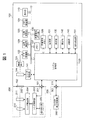
- FIG. 1 is a block diagram of a camera system including an imaging device.
- FIG. 2 is a flowchart of function control processing.
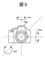
- FIG. 3 is a diagram for explaining a correction direction in image shake correction.
- FIG. 4A and FIG. 4B It is a figure which shows the detected vibration amount and the correction amount for correct
- FIG. 5 is a view showing an aspect of control of an image shake correction function according to the presence or absence of interference of a drive frequency.
- FIG. 6 is a diagram showing an aspect of control of a follow shot photographing function according to the presence or absence of interference of a drive frequency.
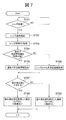
- FIG. 7 is a flowchart of function control processing.
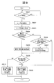
- FIG. 8 is a flowchart of function control processing.
- FIG. 1 is a block diagram of a camera system including an imaging device according to a first embodiment of the present invention.
- This camera system is configured by mounting the lens unit 200, which is a removable interchangeable lens, on the imaging device 100.
- an optical image of an object is formed on the imaging element 121 via the lens 210, the aperture stop 211, the lens mounts 102 and 202, and the shutter 144, and the optical image is converted into an electrical signal.
- the A / D converter 122 converts an analog signal output from the image sensor 121 into a digital signal.
- the digital signal A / D converted by the A / D conversion unit 122 is controlled by the memory control unit 124 and the system control unit 120, and is stored in the memory 127.
- the image processing unit 123 performs predetermined pixel interpolation processing and color conversion processing on the digital signal data A / D converted by the A / D conversion unit 122.
- the image processing unit 123 also includes a compression / decompression circuit that compresses / decompresses image data by adaptive discrete cosine transform (ADCT) or the like.
- the image processing unit 123 can also read an image stored in the memory 127, perform compression processing or decompression processing, and write the processed data to the memory 127.
- the image operation unit 129 can calculate the contrast value of the captured image, measure the in-focus state of the captured image from the contrast value, and calculate the correlation value between the image data stored in the memory 127 and the current captured image. It is also possible to search for the area with the highest correlation.
- the memory control unit 124 controls transmission and reception of data between the A / D conversion unit 122, the image processing unit 123, the display device 110, the external removable memory unit 130, and the memory 127.
- the data of the A / D conversion unit 122 is written to the memory 127 via the image processing unit 123.
- the display device 110 includes a liquid crystal panel display unit and a backlight illumination unit (not shown), and enables live view shooting by sequentially displaying live image data of imaging data obtained from the imaging device 121 in real time. During live view shooting, an AF frame indicating an AF area can be superimposed on an image and displayed on the display device 110 so that the operator can recognize the position of a subject to be subjected to AF.
- the system control unit 120 can control the entire imaging apparatus 100 and can control the lens unit 200 by controlling the lens control unit 203 via the interfaces 101 and 201.
- the memory 127 can store data of photographed still images and moving images, and images for display for reproduction.
- a program stack area, a status storage area, an operation area, a work area, and an image display data area of the system control unit 120 are secured.
- Various operations are performed by the system control unit 120 using the operation area of the memory 127.
- the non-volatile memory 128 is an electrically erasable / recordable memory, and for example, a flash memory or an EEPROM is used.
- the non-volatile memory 128 stores information indicating a photographing state, a program for controlling the imaging device 100, and the like.
- the external removable memory unit 130 performs image file recording and reading on a recording medium such as a Compact Flash (registered trademark) or an SD card.
- the power supply unit 131 includes a battery, a battery detection circuit, a DC-DC converter, a switch circuit for switching a block to be energized, and the like, and detects the presence or absence of a battery, the type of battery, and the battery remaining amount. Further, the power supply unit 131 controls the DC-DC converter based on the detection result and the instruction of the system control unit 120, and supplies the necessary voltage to each block for a necessary period.
- the shutter control unit 141 controls the shutter 144 in cooperation with the lens control unit 203 that controls the diaphragm 211 based on the photometric information from the photometric unit 142.
- a photometry unit 142 performs an AE (automatic exposure) process. The light beam incident on the lens 210 is incident on the photometric unit 142 through the aperture stop 211, the lens mounts 202 and 102, and the photometric lens (not shown), whereby the exposure state of the image formed as an optical image is measured. It becomes possible.
- the photometry unit 142 also has an EF (flash light control) processing function by cooperating with the flash unit 300.
- the flash unit 300 also has a light emission function of AF auxiliary light and a flash light control function.
- the distance measuring unit 143 performs an AF process.
- a light beam incident on the lens 210 is incident on the distance measuring unit 143 via the aperture stop 211, the lens mounts 202 and 102, and a distance measuring mirror (not shown) to focus the image formed as an optical image.
- the state can be measured.
- the distance measuring unit 143 can also measure the in-focus state of the shot image according to the contrast value obtained from the image data output from the image calculation unit 129.
- the shutter 144 shields the imaging element 121 from light when not photographing, and opens to guide a light beam to the imaging element 121 during photographing.
- the operation unit 132 is an operation unit for inputting various operation instructions of the system control unit 120.
- the operation unit 132 is configured of a single switch or a combination of a switch, a dial, pointing by sight detection, a voice recognition device, and the like.
- the shake detection unit 151 is, for example, an angular velocity sensor, and is a detection unit that detects an amount of vibration inside the imaging device 100.
- the shake detecting unit 151 can detect vibrations in three axial directions, that is, the pitch direction, the yaw direction, and the roll direction, as shown in FIG.
- the lens mount 102 and the lens mount 202 are mechanical holding mechanisms for connecting the imaging device 100 to the lens unit 200.
- the lens mounts 102 and 202 have connection terminals for electrically connecting the imaging device 100 to the lens unit 200, and the system control unit 120 communicates with the lens control unit 203 via the connection terminals.
- the accessory shoes 111 and 301 are interfaces for connecting the flash unit 300 to the imaging device 100.
- the lens unit 200 can guide an optical image of an object (not shown) from the lens 210 through the aperture stop 211, the lens mounts 202 and 102, and the shutter 144, and form an image on the imaging device 121.
- the lens control unit 203 controls the entire lens unit 200.
- the lens control unit 203 also has a non-volatile memory function.
- memory for storing operation constants, variables, programs etc., identification information (lens ID) such as number unique to the lens unit 200, management information, open aperture value, minimum aperture value, focal distance etc. Function information and current and past setting values are stored.
- “non-volatile memory” of the lens control unit 203 holds “frequency information” indicating a drive frequency of the lens drive unit 204 and the like.
- the lens control unit 203 controls focusing of the lens 210 according to the focusing state of the image measured by the distance measuring unit 143 or the image processing unit 123, and changes the imaging position of the subject image incident on the imaging element 121.
- the AF operation can be performed by doing this.
- the lens control unit 203 also has a function of controlling the diaphragm 211 and controlling the zooming of the lens 210.
- the lens drive unit 204 drives the lens 210 and the aperture 211.
- the lens driving unit 204 receives the focusing control signal, the zooming control signal, and the image blur correction control signal from the lens control unit 203, and drives the lens 210. Further, the lens drive unit 204 receives the diaphragm control signal to drive the diaphragm 211.
- the lens drive unit 204 includes the focusing control mechanism, the zooming control mechanism, the image blur correction control mechanism, and the aperture control mechanism described above.
- the shake detection unit 205 includes, for example, a gyro sensor, and detects an amount of vibration inside the lens unit 200. The shake detection unit 205 can detect vibration in two axial directions, the Pitch direction and the Yaw direction, among the Pitch direction, the Yaw direction, and the Roll direction.
- the strobe unit 300 can be connected to the accessory shoe 111.
- the interface 301 electrically connects the flash unit 300 and the imaging apparatus 100 in the accessory shoe 111.
- the flash control unit 302 controls the entire flash unit 300, and controls the amount and timing of light emission based on the information from the light measuring unit 142 with respect to a light emitting unit such as a xenon tube (not shown).
- the follow shot shooting function is a function of shooting while following the movement of a moving subject, and by applying the image blur correction function, it is possible to suppress the shake of the subject and enable shooting with a background.
- the system control unit 120 acquires frequency information of the lens unit 200, and controls the above-described function based on the acquired frequency information. Specifically, the control mode of the image blurring correction of the imaging device 100 is changed according to the frequency information of the lens unit 200 mounted.
- FIG. 2 is a flowchart of the function control process.
- the processing of this flowchart is realized by the system control unit 120 developing the program stored in the non-volatile memory 128 in the memory 127 and executing the program.
- This process is started when the power of the imaging apparatus 100 is turned on or when the operation unit 132 is operated in the on state.
- the system control unit 120 corresponds to control means and acquisition means in the present invention.
- step S201 the system control unit 120 determines whether the lens unit 200 is attached to the imaging apparatus 100 via the lens mounts 202 and 102, and continues the determination until the lens unit 200 is attached.
- the system control unit 120 starts communication with the lens control unit 203 of the attached lens unit 200 in step S202.
- step S203 the system control unit 120 acquires lens information for specifying the attached lens unit 200 from the lens control unit 203 by communication.
- the lens information includes, for example, a lens ID and optical correction value information unique to the lens.
- step S204 the system control unit 120 acquires frequency information indicating the drive frequency of the lens drive unit 204 by communication.
- step S205 the system control unit 120 determines whether the drive frequency of the lens drive unit 204 indicated by the frequency information acquired in step S204 interferes with the drive frequency of the shake detection unit 151 in the imaging device 100. Do. For example, when the ratio or difference between the two is within a predetermined range, it is determined that interference occurs. As a result of the determination, if there is no interference of the drive frequency between both the lens drive unit 204 and the shake detection unit 151, the process proceeds to step S207. If there is interference of the drive frequency between the both, the process proceeds to step S206. After steps S206 and S207, the process of FIG. 2 ends.
- step S207 the system control unit 120 normally controls the function using the shake detection unit 151, for example, the image shake correction function and the follow shot photographing function without prohibiting or restricting.
- step S206 the system control unit 120 restricts the function using the shake detection unit 151 such as prohibition.
- FIG. 3 is a diagram for explaining a correction direction in image shake correction of the imaging device 100.
- the vibration directions of camera shake or the like detected by the shake detection unit 151 are three axial directions orthogonal to each other in the pitch direction, the Yaw direction, and the Roll direction.
- the Roll direction is around the photographing optical axis (the direction in which the imaging surface rotates in a plane perpendicular to the optical axis).
- the Pitch direction is the tilting direction (tilting direction) with respect to the horizontal plane.
- the yaw direction is the tilting direction (panning direction) with respect to the vertical plane.
- Lens image stabilization (optical correction), sensor image stabilization (optical correction), and electronic image stabilization (reading range movement) may be adopted as the image shake correction function.
- the image blur correction function of the imaging device 100 is realized.
- Optical correction by the lens control unit 203 can be performed in the Pitch direction and the Yaw direction.
- the electronic correction performed by the system control unit 120 is usually performed in the Roll direction.
- Some lens units 200 do not have an optical correction mechanism. When such a lens unit 200 is attached, the system control unit 120 electronically performs correction not only in the Roll direction but also in the Pitch direction and the Yaw direction.
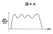
- FIG. 4A is a diagram showing the detected amount of vibration.
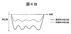
- FIG. 4B is a diagram showing a correction amount for correcting the image blur in accordance with the vibration amount.
- the vibration amount shown in FIG. 4A may be either the output of the shake detection unit 151 of the imaging device 100 or the output of the shake detection unit 205 of the lens unit 200, but here, the output is the shake detection unit 151.
- the main body of performing the shake correction may be either the system control unit 120 or the lens control unit 203, the system control unit 120 will be described here.
- the shake detecting unit 151 detects a vibration, and transmits a vibration amount as a detection result to the system control unit 120 as an analog signal or digital data.
- the system control unit 120 calculates the correction amount from the received data of the vibration amount. For example, if calculation is simply performed to cancel the vibration without limiting the image blur correction function, the system control unit 120 inverts the vibration amount of FIG. 4A as shown by a solid line in FIG. 4B. The correction amount at the normal time is calculated, and the image blur correction function is controlled. In addition, when limiting the image blur correction function, the system control unit 120 calculates the correction amount at the time of limitation by halving the correction amount at the normal time, as shown by a dotted line in FIG. Control.
- step S207 of FIG. 2 the system control unit 120 permits correction in all three directions shown in FIG. 3, for example.
- the correction amount is reduced (for example, halved) as indicated by a dotted line in FIG. 4B.
- the correction amount is set to zero or the image blur correction function itself is not performed (prohibited).
- FIG. 5 is a diagram showing an aspect of control of the image shake correction function based on the presence or absence of the interference of the drive frequency between both the lens drive unit 204 and the shake detection unit 151.
- the mode of permission of the image blur correction function differs between the “interfering lens” having the lens driving unit 204 that interferes with the drive frequency of the shake detection unit 151 and the “non-interference lens” that does not.
- whether or not the lens unit 200 has an image blur correction function is an IS compatible lens
- the manner of permission or rejection of the image blur correction function differs depending on the direction of the shake.
- the system control unit 120 permits the image blur correction function in three directions by the imaging device 100 without prohibiting or restricting the same as in the related art. Further, the system control unit 120 permits the lens control unit 203 to perform correction in the Pitch direction and the Yaw direction with respect to the lens unit 200 that does not interfere and has an image blur correction function. On the other hand, with respect to the interfering lenses, the system control unit 120 prohibits or restricts the image blur correction function in three directions by the imaging device 100. Here, the correction in the Pitch direction and the Yaw direction performed by the lens control unit 203 based on the detection result of the shake detection unit 205 is not affected by the interference.
- the system control unit 120 permits the lens control unit 203 to perform shake correction in the Pitch direction and the Yaw direction with respect to the lens unit 200 that is an interfering lens and has an image shake correction function. Therefore, the optical correction that the lens control unit 203 performs in the Pitch direction and the Yaw direction is permitted without limitation.
- FIG. 6 is a diagram showing an aspect of control of the follow shot photographing function according to the presence or absence of interference of the drive frequency.
- the mode of permission of the follow shot photographing function differs depending on the interfering lens and the non-interfering lens.
- the image shake is corrected based on the difference between the panning angular velocity of the imaging device 100 detected by the shake detection unit 151 and the angular velocity of the subject acquired by the system control unit 120 from the photographed image.
- the system control unit 120 can realize an appropriate background flow by controlling the shutter speed in accordance with the flow degree of the background from the panning angular velocity and the movement amount of the subject.
- the background flow degree can be set, for example, in three stages as shown in FIG. 6 according to the preference of the user. That is, there are three possible modes with the background flow degree being "large”, “standard: medium”, and "small”.
- the user can also set the background flow degree.
- the system control unit 120 applies (permits) all three modes without prohibiting or restricting the control of the follow shot imaging function. Therefore, setting of the background flow degree can be handled in three steps.
- the system control unit 120 limits the flow degree of the background of the follow shot photographing function so as to correspond to only the standard setting. The reason for reducing the number of applicable modes in this way is to prevent the expected flow effect from being obtained or the flow effect from becoming too large.
- the system control unit 120 prohibits or limits the function using the detection result of the shake detection unit 151. Do. Thereby, the influence of the noise due to the vibration received from the lens unit 200 can be suppressed.
- the function of using the detection result of the shake detection unit 151 is controlled based on the frequency information acquired from the mounted lens unit 200.
- the above function is prohibited or limited, so that erroneous correction or overcorrection can be avoided.
- the function is permitted without being prohibited or restricted, so that the function is sufficiently performed by the original control.
- the correction amount is reduced by half as compared to that in the normal case, so that the degree can be mitigated even in the case of erroneous correction or over correction.
- the degree of correction may be made smaller than the control in the case where there is no interference, and it is not limited to half.
- the setting step of the corresponding background flow degree is set to one step when restricting the follow shot photographing function, erroneous correction and over correction can be avoided. From this point of view, when limiting the function, the number of modes to be applied may be reduced as compared with the control in the absence of the interference.
- the image blur correction function in the imaging apparatus 100 is limited, the image blur correction function is controlled by the lens unit 200 using the detection result of the blur detection unit 205 of the lens unit 200. Permitted. Thereby, the function control by the lens unit 200 is not wasted.
- the system control unit 120 directly acquires frequency information by communication.
- frequency information can not always be obtained directly by communication. Therefore, in the second embodiment of the present invention, control is divided depending on whether or not frequency information can be directly obtained by communication. This embodiment will be described using FIG. 7 instead of FIG. 2 with respect to the first embodiment.
- FIG. 7 is a flowchart of the function control process.
- the start condition of the process of this flowchart is the same as the process of FIG.
- the system control unit 120 executes the same processing as steps S201 to S203 of FIG.
- the lens information acquired in step S703 includes information indicating whether or not the drive frequency of the lens drive unit 204 can be acquired by communication.
- step S704 the system control unit 120 determines, based on the acquired lens information, whether the drive frequency of the lens driving unit 204 of the mounted lens unit 200 can be acquired by communication. Then, if the system control unit 120 determines that the drive frequency can be acquired by communication, the process proceeds to step S705, and if it is determined that the drive frequency can not be acquired, the process proceeds to step S706. In step S705, the system control unit 120 acquires frequency information through communication by the same processing as step S204 in FIG. Thereafter, the processing proceeds to step S 707.
- step S706 the system control unit 120 acquires frequency information from the imaging apparatus 100 based on the lens ID of the lens information. Specifically, frequency information associated with the lens ID is stored in advance in a storage unit, for example, the non-volatile memory 128. The system control unit 120 acquires, among the frequency information stored in the non-volatile memory 128, one corresponding to the acquired lens ID as frequency information of the lens driving unit 204 of the lens unit 200 mounted. As a result, the system control unit 120 can acquire frequency information of the lens drive unit 204 even if the lens unit 200 can not acquire frequency information by communication. Thereafter, the processing proceeds to step S 707.
- step S707 to S709 the system control unit 120 executes the same processing as in steps S205 to S207 in FIG. 2, and ends the processing in FIG.
- the first embodiment relates to avoiding improper execution of the function using the detection result of the shake detection unit 151 due to the frequency information on the lens unit 200. Similar effects can be achieved.
- the lens unit 200 is mounted such that frequency information can not be obtained by communication, the frequency information can be obtained. Therefore, it is possible to determine whether or not the drive frequency of the shake detection unit 151 interferes, and appropriate control of the above function is possible.
- storing frequency information in the non-volatile memory 128 enables acquisition of frequency information without communication.
- the frequency information to be stored in the non-volatile memory 128 is limited, and it is difficult to obtain frequency information corresponding to any lens unit 200 from the non-volatile memory 128. Therefore, in the third embodiment of the present invention, when frequency information can not be obtained as a result, the function using the detection result of the shake detection unit 151 is prohibited or restricted.
- the present embodiment will be described using FIG. 8 in place of FIG. Similar to the second embodiment, the frequency information associated with the lens ID is stored in advance in, for example, the non-volatile memory 128.
- FIG. 8 is a flowchart of the function control process.
- the start conditions of the process of this flowchart are the same as the process of FIG.
- the system control unit 120 executes the same processing as steps S701 to S705 in FIG.
- the lens information acquired in step S 803 includes information indicating whether the drive frequency of the lens drive unit 204 can be acquired by communication.
- step S806 the system control unit 120 determines whether frequency information can be acquired from the imaging apparatus 100 based on the lens ID in the lens information.
- the system control unit 120 determines that the frequency information stored in the non-volatile memory 128 can be obtained if it corresponds to the acquired lens ID, and advances the process to step S807.
- the system control unit 120 determines that acquisition is not possible, and advances the process to step S809.
- step S807 the system control unit 120 executes the same process as step S706 in FIG. 7 and advances the process to step S808.
- steps S808 to S810 the system control unit 120 executes the same processing as steps S707 to S709 in FIG. 7 and ends the processing in FIG.
- step S806 the function restriction is also applied to the lens unit 200 in which the frequency information of the lens driving unit 204 is not stored in the non-volatile memory 128.
- the lens unit 200 which can not specify the frequency information is attached, it is unclear whether the drive frequency of the lens drive unit 204 interferes with the drive frequency of the shake detection unit 151. Therefore, it is because it is appropriate to prevent or limit the function uniformly in order to avoid the erroneous correction or the overcorrection.
- the first embodiment relates to avoiding improper execution of the function using the detection result of the shake detection unit 151 due to the frequency information on the lens unit 200. Similar effects can be achieved. In addition, when the frequency information can not be obtained, by prohibiting or restricting the above-mentioned function, it is not necessary to execute an inappropriate correction.
- a value obtained by inverting the output of the shake detection unit 151 is used as the correction amount, but the calculation method of the correction is not limited to the example.
- the frequency information corresponding to the lens ID is acquired from the non-volatile memory 128 in step S706 of FIG. 7 and step S807 of FIG.
- the determination in steps S707 and S808 may be performed based on the lens ID itself.
- the shake detection unit 151 which is an angular velocity sensor, is illustrated as a detection unit that detects shake of the imaging device 100.
- the detection unit is not limited to this.
- the shake may be detected from a motion vector acquired from a captured image.
- the image shake correction function and the follow shot imaging function are illustrated as the functions using the detection result of the shake detection unit 151, the functions are not limited to these.
- a drive frequency may be a target irrespective of a continuous drive frequency or an intermittent drive frequency.
- the lens unit 200 is illustrated as an accessory to be attached to and detached from the imaging apparatus 100, the accessory is not limited to this, and an accessory having a drive unit (for example, an outside having a zoom mechanism using a drive unit or a rotation mechanism Can be targeted if it is
- the present invention is also realized by performing the following processing. That is, software (program) for realizing the functions of the above-described embodiment is supplied to a system or apparatus via a network or various storage media, and a computer (or CPU, MPU or the like) of the system or apparatus reads out a program code. It is a process to execute. In this case, the program and the storage medium storing the program constitute the present invention.
Landscapes
- Physics & Mathematics (AREA)
- Engineering & Computer Science (AREA)
- Multimedia (AREA)
- Signal Processing (AREA)
- General Physics & Mathematics (AREA)
- Optics & Photonics (AREA)
- Adjustment Of Camera Lenses (AREA)
- Studio Devices (AREA)
Priority Applications (2)
| Application Number | Priority Date | Filing Date | Title |
|---|---|---|---|
| CN201780077819.XA CN110088677B (zh) | 2016-12-16 | 2017-10-12 | 摄像设备及其控制方法和存储介质 |
| US16/432,335 US10845613B2 (en) | 2016-12-16 | 2019-06-05 | Image pickup apparatus executing function based on shake, control method for same, and storage medium storing control program therefor |
Applications Claiming Priority (2)
| Application Number | Priority Date | Filing Date | Title |
|---|---|---|---|
| JP2016244319A JP6720070B2 (ja) | 2016-12-16 | 2016-12-16 | 撮像装置及びその制御方法、プログラム |
| JP2016-244319 | 2016-12-16 |
Related Child Applications (1)
| Application Number | Title | Priority Date | Filing Date |
|---|---|---|---|
| US16/432,335 Continuation US10845613B2 (en) | 2016-12-16 | 2019-06-05 | Image pickup apparatus executing function based on shake, control method for same, and storage medium storing control program therefor |
Publications (1)
| Publication Number | Publication Date |
|---|---|
| WO2018110076A1 true WO2018110076A1 (ja) | 2018-06-21 |
Family
ID=62558272
Family Applications (1)
| Application Number | Title | Priority Date | Filing Date |
|---|---|---|---|
| PCT/JP2017/037769 Ceased WO2018110076A1 (ja) | 2016-12-16 | 2017-10-12 | 撮像装置及びその制御方法、プログラム |
Country Status (4)
| Country | Link |
|---|---|
| US (1) | US10845613B2 (enExample) |
| JP (1) | JP6720070B2 (enExample) |
| CN (1) | CN110088677B (enExample) |
| WO (1) | WO2018110076A1 (enExample) |
Families Citing this family (4)
| Publication number | Priority date | Publication date | Assignee | Title |
|---|---|---|---|---|
| JP7099108B2 (ja) * | 2018-07-13 | 2022-07-12 | 株式会社ニコン | 交換レンズ及びカメラボディ |
| WO2021102878A1 (zh) * | 2019-11-29 | 2021-06-03 | 深圳市大疆创新科技有限公司 | 一种拍摄装置的配置方法及其装置 |
| JP7500194B2 (ja) * | 2019-12-27 | 2024-06-17 | キヤノン株式会社 | 撮像装置及びその制御方法、プログラム、記憶媒体 |
| JP7483407B2 (ja) * | 2020-02-27 | 2024-05-15 | キヤノン株式会社 | 撮像装置及び制御方法 |
Citations (4)
| Publication number | Priority date | Publication date | Assignee | Title |
|---|---|---|---|---|
| JPH07159833A (ja) * | 1993-12-06 | 1995-06-23 | Nikon Corp | 像ブレ補正撮影装置 |
| JPH0980549A (ja) * | 1995-09-13 | 1997-03-28 | Nikon Corp | ブレ補正機構付き光学装置 |
| JP2007304456A (ja) * | 2006-05-15 | 2007-11-22 | Canon Inc | 像振れ補正装置およびカメラ |
| JP2010273335A (ja) * | 2009-04-23 | 2010-12-02 | Panasonic Corp | ぶれ補正装置とそれを備えた撮像装置 |
Family Cites Families (9)
| Publication number | Priority date | Publication date | Assignee | Title |
|---|---|---|---|---|
| JPH10177195A (ja) * | 1996-12-17 | 1998-06-30 | Nikon Corp | ブレ補正装置及びレンズ装置 |
| JP4769553B2 (ja) * | 2005-11-16 | 2011-09-07 | キヤノン株式会社 | 撮像装置 |
| JP2007251656A (ja) * | 2006-03-16 | 2007-09-27 | Canon Inc | 撮像装置、その制御方法およびプログラム |
| JP5188138B2 (ja) * | 2007-10-15 | 2013-04-24 | キヤノン株式会社 | 像ぶれ補正装置を有する光学機器 |
| JP5302654B2 (ja) * | 2007-12-20 | 2013-10-02 | パナソニック株式会社 | 撮像装置、交換レンズユニット、カメラボディー、超音波モータ駆動装置 |
| JP5612917B2 (ja) * | 2010-06-22 | 2014-10-22 | キヤノン株式会社 | 光学機器及びその制御方法 |
| JP2016048289A (ja) | 2014-08-27 | 2016-04-07 | キヤノン株式会社 | 撮像装置、撮像装置の制御方法、およびコンピュータプログラム |
| US9715162B2 (en) * | 2015-08-19 | 2017-07-25 | Canon Kabushiki Kaisha | Vibration motor controller, and lens apparatus and image pickup apparatus that include the same |
| JP2019146037A (ja) * | 2018-02-21 | 2019-08-29 | キヤノン株式会社 | 画像処理装置とその制御方法、及びプログラム |
-
2016
- 2016-12-16 JP JP2016244319A patent/JP6720070B2/ja active Active
-
2017
- 2017-10-12 WO PCT/JP2017/037769 patent/WO2018110076A1/ja not_active Ceased
- 2017-10-12 CN CN201780077819.XA patent/CN110088677B/zh active Active
-
2019
- 2019-06-05 US US16/432,335 patent/US10845613B2/en active Active
Patent Citations (4)
| Publication number | Priority date | Publication date | Assignee | Title |
|---|---|---|---|---|
| JPH07159833A (ja) * | 1993-12-06 | 1995-06-23 | Nikon Corp | 像ブレ補正撮影装置 |
| JPH0980549A (ja) * | 1995-09-13 | 1997-03-28 | Nikon Corp | ブレ補正機構付き光学装置 |
| JP2007304456A (ja) * | 2006-05-15 | 2007-11-22 | Canon Inc | 像振れ補正装置およびカメラ |
| JP2010273335A (ja) * | 2009-04-23 | 2010-12-02 | Panasonic Corp | ぶれ補正装置とそれを備えた撮像装置 |
Also Published As
| Publication number | Publication date |
|---|---|
| CN110088677A (zh) | 2019-08-02 |
| US10845613B2 (en) | 2020-11-24 |
| US20190285908A1 (en) | 2019-09-19 |
| CN110088677B (zh) | 2021-07-16 |
| JP6720070B2 (ja) | 2020-07-08 |
| JP2018097301A (ja) | 2018-06-21 |
Similar Documents
| Publication | Publication Date | Title |
|---|---|---|
| JP6472176B2 (ja) | 撮像装置、像振れ補正装置、撮像装置の制御方法及び像振れ補正方法 | |
| JP6700872B2 (ja) | 像振れ補正装置及びその制御方法、撮像装置、プログラム、記憶媒体 | |
| US9906708B2 (en) | Imaging apparatus, imaging method, and non-transitory storage medium storing imaging program for controlling an auto-focus scan drive | |
| US10845613B2 (en) | Image pickup apparatus executing function based on shake, control method for same, and storage medium storing control program therefor | |
| JP2017211487A (ja) | 撮像装置及び自動焦点調節方法 | |
| WO2020044803A1 (ja) | 撮像装置、撮像方法、及びプログラム | |
| JP4671705B2 (ja) | 撮像装置 | |
| US20220264010A1 (en) | Lens apparatus, image pickup system, control method of lens apparatus, and storage medium | |
| JPWO2018186176A1 (ja) | 撮像装置、撮像用制御方法、及びプログラム | |
| JP6432038B2 (ja) | 撮像装置 | |
| JP6543946B2 (ja) | ブレ補正装置、カメラ及び電子機器 | |
| US11350036B2 (en) | Image pickup apparatus and lens device that have image blur correction function | |
| US10511784B2 (en) | Imaging apparatus and control method therefor, and external device | |
| JP2003098567A (ja) | カメラ | |
| JP2002267924A (ja) | 光学機器システム | |
| US10477109B2 (en) | Imaging apparatus and control method therefor | |
| JP7451152B2 (ja) | 撮像装置、制御方法及びコンピュータプログラム | |
| US11956538B2 (en) | Image capturing apparatus that performs blur correction and method of controlling same | |
| JP2007199182A (ja) | 防振機能付きカメラ | |
| US11924558B2 (en) | Image pickup apparatus that performs optical image blur correction and alignment composition of plurality of still images shot in time continuous manner, control method thereof, and storage medium | |
| JP2014035536A (ja) | 撮影装置及び回転光学要素の回転駆動制御方法 | |
| JP5110799B2 (ja) | 防振機能付きカメラ | |
| JP2024071858A (ja) | ブレ補正装置、ブレ補正方法及び撮像装置 | |
| JP2023070454A (ja) | 画像処理装置及び方法、及び撮像装置 | |
| JP2021099452A (ja) | 光学機器、撮像装置および制御方法 |
Legal Events
| Date | Code | Title | Description |
|---|---|---|---|
| 121 | Ep: the epo has been informed by wipo that ep was designated in this application |
Ref document number: 17881630 Country of ref document: EP Kind code of ref document: A1 |
|
| NENP | Non-entry into the national phase |
Ref country code: DE |
|
| 122 | Ep: pct application non-entry in european phase |
Ref document number: 17881630 Country of ref document: EP Kind code of ref document: A1 |