WO2018110076A1 - Imaging device, method for controlling same, and program - Google Patents
Imaging device, method for controlling same, and program Download PDFInfo
- Publication number
- WO2018110076A1 WO2018110076A1 PCT/JP2017/037769 JP2017037769W WO2018110076A1 WO 2018110076 A1 WO2018110076 A1 WO 2018110076A1 JP 2017037769 W JP2017037769 W JP 2017037769W WO 2018110076 A1 WO2018110076 A1 WO 2018110076A1
- Authority
- WO
- WIPO (PCT)
- Prior art keywords
- unit
- function
- lens
- frequency information
- imaging device
- Prior art date
Links
Images


Classifications
-
- G—PHYSICS
- G02—OPTICS
- G02B—OPTICAL ELEMENTS, SYSTEMS OR APPARATUS
- G02B27/00—Optical systems or apparatus not provided for by any of the groups G02B1/00 - G02B26/00, G02B30/00
- G02B27/64—Imaging systems using optical elements for stabilisation of the lateral and angular position of the image
- G02B27/646—Imaging systems using optical elements for stabilisation of the lateral and angular position of the image compensating for small deviations, e.g. due to vibration or shake
-
- G—PHYSICS
- G03—PHOTOGRAPHY; CINEMATOGRAPHY; ANALOGOUS TECHNIQUES USING WAVES OTHER THAN OPTICAL WAVES; ELECTROGRAPHY; HOLOGRAPHY
- G03B—APPARATUS OR ARRANGEMENTS FOR TAKING PHOTOGRAPHS OR FOR PROJECTING OR VIEWING THEM; APPARATUS OR ARRANGEMENTS EMPLOYING ANALOGOUS TECHNIQUES USING WAVES OTHER THAN OPTICAL WAVES; ACCESSORIES THEREFOR
- G03B17/00—Details of cameras or camera bodies; Accessories therefor
- G03B17/02—Bodies
- G03B17/12—Bodies with means for supporting objectives, supplementary lenses, filters, masks, or turrets
- G03B17/14—Bodies with means for supporting objectives, supplementary lenses, filters, masks, or turrets interchangeably
-
- G—PHYSICS
- G03—PHOTOGRAPHY; CINEMATOGRAPHY; ANALOGOUS TECHNIQUES USING WAVES OTHER THAN OPTICAL WAVES; ELECTROGRAPHY; HOLOGRAPHY
- G03B—APPARATUS OR ARRANGEMENTS FOR TAKING PHOTOGRAPHS OR FOR PROJECTING OR VIEWING THEM; APPARATUS OR ARRANGEMENTS EMPLOYING ANALOGOUS TECHNIQUES USING WAVES OTHER THAN OPTICAL WAVES; ACCESSORIES THEREFOR
- G03B5/00—Adjustment of optical system relative to image or object surface other than for focusing
-
- H—ELECTRICITY
- H04—ELECTRIC COMMUNICATION TECHNIQUE
- H04N—PICTORIAL COMMUNICATION, e.g. TELEVISION
- H04N23/00—Cameras or camera modules comprising electronic image sensors; Control thereof
- H04N23/60—Control of cameras or camera modules
-
- H—ELECTRICITY
- H04—ELECTRIC COMMUNICATION TECHNIQUE
- H04N—PICTORIAL COMMUNICATION, e.g. TELEVISION
- H04N23/00—Cameras or camera modules comprising electronic image sensors; Control thereof
- H04N23/60—Control of cameras or camera modules
- H04N23/66—Remote control of cameras or camera parts, e.g. by remote control devices
- H04N23/663—Remote control of cameras or camera parts, e.g. by remote control devices for controlling interchangeable camera parts based on electronic image sensor signals
-
- H—ELECTRICITY
- H04—ELECTRIC COMMUNICATION TECHNIQUE
- H04N—PICTORIAL COMMUNICATION, e.g. TELEVISION
- H04N23/00—Cameras or camera modules comprising electronic image sensors; Control thereof
- H04N23/60—Control of cameras or camera modules
- H04N23/667—Camera operation mode switching, e.g. between still and video, sport and normal or high- and low-resolution modes
-
- H—ELECTRICITY
- H04—ELECTRIC COMMUNICATION TECHNIQUE
- H04N—PICTORIAL COMMUNICATION, e.g. TELEVISION
- H04N23/00—Cameras or camera modules comprising electronic image sensors; Control thereof
- H04N23/60—Control of cameras or camera modules
- H04N23/68—Control of cameras or camera modules for stable pick-up of the scene, e.g. compensating for camera body vibrations
- H04N23/681—Motion detection
- H04N23/6812—Motion detection based on additional sensors, e.g. acceleration sensors
-
- H—ELECTRICITY
- H04—ELECTRIC COMMUNICATION TECHNIQUE
- H04N—PICTORIAL COMMUNICATION, e.g. TELEVISION
- H04N23/00—Cameras or camera modules comprising electronic image sensors; Control thereof
- H04N23/60—Control of cameras or camera modules
- H04N23/68—Control of cameras or camera modules for stable pick-up of the scene, e.g. compensating for camera body vibrations
- H04N23/681—Motion detection
- H04N23/6815—Motion detection by distinguishing pan or tilt from motion
-
- H—ELECTRICITY
- H04—ELECTRIC COMMUNICATION TECHNIQUE
- H04N—PICTORIAL COMMUNICATION, e.g. TELEVISION
- H04N23/00—Cameras or camera modules comprising electronic image sensors; Control thereof
- H04N23/60—Control of cameras or camera modules
- H04N23/68—Control of cameras or camera modules for stable pick-up of the scene, e.g. compensating for camera body vibrations
- H04N23/682—Vibration or motion blur correction
- H04N23/685—Vibration or motion blur correction performed by mechanical compensation
- H04N23/687—Vibration or motion blur correction performed by mechanical compensation by shifting the lens or sensor position
-
- G—PHYSICS
- G03—PHOTOGRAPHY; CINEMATOGRAPHY; ANALOGOUS TECHNIQUES USING WAVES OTHER THAN OPTICAL WAVES; ELECTROGRAPHY; HOLOGRAPHY
- G03B—APPARATUS OR ARRANGEMENTS FOR TAKING PHOTOGRAPHS OR FOR PROJECTING OR VIEWING THEM; APPARATUS OR ARRANGEMENTS EMPLOYING ANALOGOUS TECHNIQUES USING WAVES OTHER THAN OPTICAL WAVES; ACCESSORIES THEREFOR
- G03B2205/00—Adjustment of optical system relative to image or object surface other than for focusing
- G03B2205/0007—Movement of one or more optical elements for control of motion blur
- G03B2205/0015—Movement of one or more optical elements for control of motion blur by displacing one or more optical elements normal to the optical axis
-
- G—PHYSICS
- G03—PHOTOGRAPHY; CINEMATOGRAPHY; ANALOGOUS TECHNIQUES USING WAVES OTHER THAN OPTICAL WAVES; ELECTROGRAPHY; HOLOGRAPHY
- G03B—APPARATUS OR ARRANGEMENTS FOR TAKING PHOTOGRAPHS OR FOR PROJECTING OR VIEWING THEM; APPARATUS OR ARRANGEMENTS EMPLOYING ANALOGOUS TECHNIQUES USING WAVES OTHER THAN OPTICAL WAVES; ACCESSORIES THEREFOR
- G03B2217/00—Details of cameras or camera bodies; Accessories therefor
- G03B2217/005—Blur detection
Definitions
- the present invention relates to an imaging apparatus and the like that can be attached and detached with an accessory such as an interchangeable lens and that performs a function based on shake.
- imaging devices such as cameras that detect shake of the imaging device body and execute functions such as image shake correction based on the detected shake are known.
- a shake detection sensor such as an angular velocity sensor is used to detect the amount of camera shake. Based on the detected shake, a part or all of the photographing optical system is driven to perform image shake correction on the image forming surface.
- the imaging apparatus has various vibration sources such as, for example, a mirror and a shutter drive unit, an ultrasonic motor that performs focus control of a lens, and a stepping motor. Since the sensitivity of the shake detection sensor is very sensitive, the shake detection sensor is subject to vibration interference when vibration due to the vibration source occurs at a cycle close to the drive frequency of the shake detection sensor. Then, since the noise component generated by the interference is superimposed on the output of the shake detection sensor, there is a problem that appropriate image shake correction can not be performed. Therefore, in Patent Document 1, when the imaging device changes the reading frequency of the imaging unit or the driving frequency of the driving unit, the driving frequency of the shake detection sensor is changed to cause the sensor to generate vibration or noise in the imaging device. It avoids receiving interference.
- a mirror and a shutter drive unit an ultrasonic motor that performs focus control of a lens
- a stepping motor Since the sensitivity of the shake detection sensor is very sensitive, the shake detection sensor is subject to vibration interference when vibration due to the vibration source occurs at a cycle close to the
- the drive unit in these accessories is driven at a unique driving frequency that can not be controlled by the imaging device. Therefore, the shake detection sensor in the imaging device may be interfered by the vibration generated by the attached accessory. That is, when the drive frequency of the drive unit in the accessory and the drive frequency of the shake detection sensor interfere with each other, appropriate correction can not be performed, which may result in erroneous correction or over correction.
- a function such as shake correction is performed based on the output of the shake detection sensor while the drive frequency of the drive unit in the accessory is unknown on the imaging device side, the function may not be properly performed due to interference.
- An object of the present invention is to prevent inappropriate execution of a function using a result of shake detection due to frequency information on an accessory.
- the present invention uses a detection unit that detects a shake of an imaging device, an acquisition unit that acquires frequency information on an accessory attached to the imaging device, and a detection result of the detection unit. And control means for controlling a function, wherein the control means controls the function based on frequency information acquired by the acquisition means.
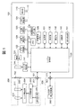
- FIG. 1 is a block diagram of a camera system including an imaging device.
- FIG. 2 is a flowchart of function control processing.
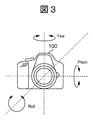
- FIG. 3 is a diagram for explaining a correction direction in image shake correction.
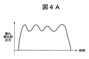
- FIG. 4A and FIG. 4B It is a figure which shows the detected vibration amount and the correction amount for correct
- FIG. 5 is a view showing an aspect of control of an image shake correction function according to the presence or absence of interference of a drive frequency.
- FIG. 6 is a diagram showing an aspect of control of a follow shot photographing function according to the presence or absence of interference of a drive frequency.
- FIG. 7 is a flowchart of function control processing.
- FIG. 8 is a flowchart of function control processing.
- FIG. 1 is a block diagram of a camera system including an imaging device according to a first embodiment of the present invention.
- This camera system is configured by mounting the lens unit 200, which is a removable interchangeable lens, on the imaging device 100.
- an optical image of an object is formed on the imaging element 121 via the lens 210, the aperture stop 211, the lens mounts 102 and 202, and the shutter 144, and the optical image is converted into an electrical signal.
- the A / D converter 122 converts an analog signal output from the image sensor 121 into a digital signal.
- the digital signal A / D converted by the A / D conversion unit 122 is controlled by the memory control unit 124 and the system control unit 120, and is stored in the memory 127.
- the image processing unit 123 performs predetermined pixel interpolation processing and color conversion processing on the digital signal data A / D converted by the A / D conversion unit 122.
- the image processing unit 123 also includes a compression / decompression circuit that compresses / decompresses image data by adaptive discrete cosine transform (ADCT) or the like.
- the image processing unit 123 can also read an image stored in the memory 127, perform compression processing or decompression processing, and write the processed data to the memory 127.
- the image operation unit 129 can calculate the contrast value of the captured image, measure the in-focus state of the captured image from the contrast value, and calculate the correlation value between the image data stored in the memory 127 and the current captured image. It is also possible to search for the area with the highest correlation.
- the memory control unit 124 controls transmission and reception of data between the A / D conversion unit 122, the image processing unit 123, the display device 110, the external removable memory unit 130, and the memory 127.
- the data of the A / D conversion unit 122 is written to the memory 127 via the image processing unit 123.
- the display device 110 includes a liquid crystal panel display unit and a backlight illumination unit (not shown), and enables live view shooting by sequentially displaying live image data of imaging data obtained from the imaging device 121 in real time. During live view shooting, an AF frame indicating an AF area can be superimposed on an image and displayed on the display device 110 so that the operator can recognize the position of a subject to be subjected to AF.
- the system control unit 120 can control the entire imaging apparatus 100 and can control the lens unit 200 by controlling the lens control unit 203 via the interfaces 101 and 201.
- the memory 127 can store data of photographed still images and moving images, and images for display for reproduction.
- a program stack area, a status storage area, an operation area, a work area, and an image display data area of the system control unit 120 are secured.
- Various operations are performed by the system control unit 120 using the operation area of the memory 127.
- the non-volatile memory 128 is an electrically erasable / recordable memory, and for example, a flash memory or an EEPROM is used.
- the non-volatile memory 128 stores information indicating a photographing state, a program for controlling the imaging device 100, and the like.
- the external removable memory unit 130 performs image file recording and reading on a recording medium such as a Compact Flash (registered trademark) or an SD card.
- the power supply unit 131 includes a battery, a battery detection circuit, a DC-DC converter, a switch circuit for switching a block to be energized, and the like, and detects the presence or absence of a battery, the type of battery, and the battery remaining amount. Further, the power supply unit 131 controls the DC-DC converter based on the detection result and the instruction of the system control unit 120, and supplies the necessary voltage to each block for a necessary period.
- the shutter control unit 141 controls the shutter 144 in cooperation with the lens control unit 203 that controls the diaphragm 211 based on the photometric information from the photometric unit 142.
- a photometry unit 142 performs an AE (automatic exposure) process. The light beam incident on the lens 210 is incident on the photometric unit 142 through the aperture stop 211, the lens mounts 202 and 102, and the photometric lens (not shown), whereby the exposure state of the image formed as an optical image is measured. It becomes possible.
- the photometry unit 142 also has an EF (flash light control) processing function by cooperating with the flash unit 300.
- the flash unit 300 also has a light emission function of AF auxiliary light and a flash light control function.
- the distance measuring unit 143 performs an AF process.
- a light beam incident on the lens 210 is incident on the distance measuring unit 143 via the aperture stop 211, the lens mounts 202 and 102, and a distance measuring mirror (not shown) to focus the image formed as an optical image.
- the state can be measured.
- the distance measuring unit 143 can also measure the in-focus state of the shot image according to the contrast value obtained from the image data output from the image calculation unit 129.
- the shutter 144 shields the imaging element 121 from light when not photographing, and opens to guide a light beam to the imaging element 121 during photographing.
- the operation unit 132 is an operation unit for inputting various operation instructions of the system control unit 120.
- the operation unit 132 is configured of a single switch or a combination of a switch, a dial, pointing by sight detection, a voice recognition device, and the like.
- the shake detection unit 151 is, for example, an angular velocity sensor, and is a detection unit that detects an amount of vibration inside the imaging device 100.
- the shake detecting unit 151 can detect vibrations in three axial directions, that is, the pitch direction, the yaw direction, and the roll direction, as shown in FIG.
- the lens mount 102 and the lens mount 202 are mechanical holding mechanisms for connecting the imaging device 100 to the lens unit 200.
- the lens mounts 102 and 202 have connection terminals for electrically connecting the imaging device 100 to the lens unit 200, and the system control unit 120 communicates with the lens control unit 203 via the connection terminals.
- the accessory shoes 111 and 301 are interfaces for connecting the flash unit 300 to the imaging device 100.
- the lens unit 200 can guide an optical image of an object (not shown) from the lens 210 through the aperture stop 211, the lens mounts 202 and 102, and the shutter 144, and form an image on the imaging device 121.
- the lens control unit 203 controls the entire lens unit 200.
- the lens control unit 203 also has a non-volatile memory function.
- memory for storing operation constants, variables, programs etc., identification information (lens ID) such as number unique to the lens unit 200, management information, open aperture value, minimum aperture value, focal distance etc. Function information and current and past setting values are stored.
- “non-volatile memory” of the lens control unit 203 holds “frequency information” indicating a drive frequency of the lens drive unit 204 and the like.
- the lens control unit 203 controls focusing of the lens 210 according to the focusing state of the image measured by the distance measuring unit 143 or the image processing unit 123, and changes the imaging position of the subject image incident on the imaging element 121.
- the AF operation can be performed by doing this.
- the lens control unit 203 also has a function of controlling the diaphragm 211 and controlling the zooming of the lens 210.
- the lens drive unit 204 drives the lens 210 and the aperture 211.
- the lens driving unit 204 receives the focusing control signal, the zooming control signal, and the image blur correction control signal from the lens control unit 203, and drives the lens 210. Further, the lens drive unit 204 receives the diaphragm control signal to drive the diaphragm 211.
- the lens drive unit 204 includes the focusing control mechanism, the zooming control mechanism, the image blur correction control mechanism, and the aperture control mechanism described above.
- the shake detection unit 205 includes, for example, a gyro sensor, and detects an amount of vibration inside the lens unit 200. The shake detection unit 205 can detect vibration in two axial directions, the Pitch direction and the Yaw direction, among the Pitch direction, the Yaw direction, and the Roll direction.
- the strobe unit 300 can be connected to the accessory shoe 111.
- the interface 301 electrically connects the flash unit 300 and the imaging apparatus 100 in the accessory shoe 111.
- the flash control unit 302 controls the entire flash unit 300, and controls the amount and timing of light emission based on the information from the light measuring unit 142 with respect to a light emitting unit such as a xenon tube (not shown).
- the follow shot shooting function is a function of shooting while following the movement of a moving subject, and by applying the image blur correction function, it is possible to suppress the shake of the subject and enable shooting with a background.
- the system control unit 120 acquires frequency information of the lens unit 200, and controls the above-described function based on the acquired frequency information. Specifically, the control mode of the image blurring correction of the imaging device 100 is changed according to the frequency information of the lens unit 200 mounted.
- FIG. 2 is a flowchart of the function control process.
- the processing of this flowchart is realized by the system control unit 120 developing the program stored in the non-volatile memory 128 in the memory 127 and executing the program.
- This process is started when the power of the imaging apparatus 100 is turned on or when the operation unit 132 is operated in the on state.
- the system control unit 120 corresponds to control means and acquisition means in the present invention.
- step S201 the system control unit 120 determines whether the lens unit 200 is attached to the imaging apparatus 100 via the lens mounts 202 and 102, and continues the determination until the lens unit 200 is attached.
- the system control unit 120 starts communication with the lens control unit 203 of the attached lens unit 200 in step S202.
- step S203 the system control unit 120 acquires lens information for specifying the attached lens unit 200 from the lens control unit 203 by communication.
- the lens information includes, for example, a lens ID and optical correction value information unique to the lens.
- step S204 the system control unit 120 acquires frequency information indicating the drive frequency of the lens drive unit 204 by communication.
- step S205 the system control unit 120 determines whether the drive frequency of the lens drive unit 204 indicated by the frequency information acquired in step S204 interferes with the drive frequency of the shake detection unit 151 in the imaging device 100. Do. For example, when the ratio or difference between the two is within a predetermined range, it is determined that interference occurs. As a result of the determination, if there is no interference of the drive frequency between both the lens drive unit 204 and the shake detection unit 151, the process proceeds to step S207. If there is interference of the drive frequency between the both, the process proceeds to step S206. After steps S206 and S207, the process of FIG. 2 ends.
- step S207 the system control unit 120 normally controls the function using the shake detection unit 151, for example, the image shake correction function and the follow shot photographing function without prohibiting or restricting.
- step S206 the system control unit 120 restricts the function using the shake detection unit 151 such as prohibition.
- FIG. 3 is a diagram for explaining a correction direction in image shake correction of the imaging device 100.
- the vibration directions of camera shake or the like detected by the shake detection unit 151 are three axial directions orthogonal to each other in the pitch direction, the Yaw direction, and the Roll direction.
- the Roll direction is around the photographing optical axis (the direction in which the imaging surface rotates in a plane perpendicular to the optical axis).
- the Pitch direction is the tilting direction (tilting direction) with respect to the horizontal plane.
- the yaw direction is the tilting direction (panning direction) with respect to the vertical plane.
- Lens image stabilization (optical correction), sensor image stabilization (optical correction), and electronic image stabilization (reading range movement) may be adopted as the image shake correction function.
- the image blur correction function of the imaging device 100 is realized.
- Optical correction by the lens control unit 203 can be performed in the Pitch direction and the Yaw direction.
- the electronic correction performed by the system control unit 120 is usually performed in the Roll direction.
- Some lens units 200 do not have an optical correction mechanism. When such a lens unit 200 is attached, the system control unit 120 electronically performs correction not only in the Roll direction but also in the Pitch direction and the Yaw direction.
- FIG. 4A is a diagram showing the detected amount of vibration.
- FIG. 4B is a diagram showing a correction amount for correcting the image blur in accordance with the vibration amount.
- the vibration amount shown in FIG. 4A may be either the output of the shake detection unit 151 of the imaging device 100 or the output of the shake detection unit 205 of the lens unit 200, but here, the output is the shake detection unit 151.
- the main body of performing the shake correction may be either the system control unit 120 or the lens control unit 203, the system control unit 120 will be described here.
- the shake detecting unit 151 detects a vibration, and transmits a vibration amount as a detection result to the system control unit 120 as an analog signal or digital data.
- the system control unit 120 calculates the correction amount from the received data of the vibration amount. For example, if calculation is simply performed to cancel the vibration without limiting the image blur correction function, the system control unit 120 inverts the vibration amount of FIG. 4A as shown by a solid line in FIG. 4B. The correction amount at the normal time is calculated, and the image blur correction function is controlled. In addition, when limiting the image blur correction function, the system control unit 120 calculates the correction amount at the time of limitation by halving the correction amount at the normal time, as shown by a dotted line in FIG. Control.
- step S207 of FIG. 2 the system control unit 120 permits correction in all three directions shown in FIG. 3, for example.
- the correction amount is reduced (for example, halved) as indicated by a dotted line in FIG. 4B.
- the correction amount is set to zero or the image blur correction function itself is not performed (prohibited).
- FIG. 5 is a diagram showing an aspect of control of the image shake correction function based on the presence or absence of the interference of the drive frequency between both the lens drive unit 204 and the shake detection unit 151.
- the mode of permission of the image blur correction function differs between the “interfering lens” having the lens driving unit 204 that interferes with the drive frequency of the shake detection unit 151 and the “non-interference lens” that does not.
- whether or not the lens unit 200 has an image blur correction function is an IS compatible lens
- the manner of permission or rejection of the image blur correction function differs depending on the direction of the shake.
- the system control unit 120 permits the image blur correction function in three directions by the imaging device 100 without prohibiting or restricting the same as in the related art. Further, the system control unit 120 permits the lens control unit 203 to perform correction in the Pitch direction and the Yaw direction with respect to the lens unit 200 that does not interfere and has an image blur correction function. On the other hand, with respect to the interfering lenses, the system control unit 120 prohibits or restricts the image blur correction function in three directions by the imaging device 100. Here, the correction in the Pitch direction and the Yaw direction performed by the lens control unit 203 based on the detection result of the shake detection unit 205 is not affected by the interference.
- the system control unit 120 permits the lens control unit 203 to perform shake correction in the Pitch direction and the Yaw direction with respect to the lens unit 200 that is an interfering lens and has an image shake correction function. Therefore, the optical correction that the lens control unit 203 performs in the Pitch direction and the Yaw direction is permitted without limitation.
- FIG. 6 is a diagram showing an aspect of control of the follow shot photographing function according to the presence or absence of interference of the drive frequency.
- the mode of permission of the follow shot photographing function differs depending on the interfering lens and the non-interfering lens.
- the image shake is corrected based on the difference between the panning angular velocity of the imaging device 100 detected by the shake detection unit 151 and the angular velocity of the subject acquired by the system control unit 120 from the photographed image.
- the system control unit 120 can realize an appropriate background flow by controlling the shutter speed in accordance with the flow degree of the background from the panning angular velocity and the movement amount of the subject.
- the background flow degree can be set, for example, in three stages as shown in FIG. 6 according to the preference of the user. That is, there are three possible modes with the background flow degree being "large”, “standard: medium”, and "small”.
- the user can also set the background flow degree.
- the system control unit 120 applies (permits) all three modes without prohibiting or restricting the control of the follow shot imaging function. Therefore, setting of the background flow degree can be handled in three steps.
- the system control unit 120 limits the flow degree of the background of the follow shot photographing function so as to correspond to only the standard setting. The reason for reducing the number of applicable modes in this way is to prevent the expected flow effect from being obtained or the flow effect from becoming too large.
- the system control unit 120 prohibits or limits the function using the detection result of the shake detection unit 151. Do. Thereby, the influence of the noise due to the vibration received from the lens unit 200 can be suppressed.
- the function of using the detection result of the shake detection unit 151 is controlled based on the frequency information acquired from the mounted lens unit 200.
- the above function is prohibited or limited, so that erroneous correction or overcorrection can be avoided.
- the function is permitted without being prohibited or restricted, so that the function is sufficiently performed by the original control.
- the correction amount is reduced by half as compared to that in the normal case, so that the degree can be mitigated even in the case of erroneous correction or over correction.
- the degree of correction may be made smaller than the control in the case where there is no interference, and it is not limited to half.
- the setting step of the corresponding background flow degree is set to one step when restricting the follow shot photographing function, erroneous correction and over correction can be avoided. From this point of view, when limiting the function, the number of modes to be applied may be reduced as compared with the control in the absence of the interference.
- the image blur correction function in the imaging apparatus 100 is limited, the image blur correction function is controlled by the lens unit 200 using the detection result of the blur detection unit 205 of the lens unit 200. Permitted. Thereby, the function control by the lens unit 200 is not wasted.
- the system control unit 120 directly acquires frequency information by communication.
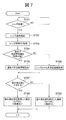
- frequency information can not always be obtained directly by communication. Therefore, in the second embodiment of the present invention, control is divided depending on whether or not frequency information can be directly obtained by communication. This embodiment will be described using FIG. 7 instead of FIG. 2 with respect to the first embodiment.
- FIG. 7 is a flowchart of the function control process.
- the start condition of the process of this flowchart is the same as the process of FIG.
- the system control unit 120 executes the same processing as steps S201 to S203 of FIG.
- the lens information acquired in step S703 includes information indicating whether or not the drive frequency of the lens drive unit 204 can be acquired by communication.
- step S704 the system control unit 120 determines, based on the acquired lens information, whether the drive frequency of the lens driving unit 204 of the mounted lens unit 200 can be acquired by communication. Then, if the system control unit 120 determines that the drive frequency can be acquired by communication, the process proceeds to step S705, and if it is determined that the drive frequency can not be acquired, the process proceeds to step S706. In step S705, the system control unit 120 acquires frequency information through communication by the same processing as step S204 in FIG. Thereafter, the processing proceeds to step S 707.
- step S706 the system control unit 120 acquires frequency information from the imaging apparatus 100 based on the lens ID of the lens information. Specifically, frequency information associated with the lens ID is stored in advance in a storage unit, for example, the non-volatile memory 128. The system control unit 120 acquires, among the frequency information stored in the non-volatile memory 128, one corresponding to the acquired lens ID as frequency information of the lens driving unit 204 of the lens unit 200 mounted. As a result, the system control unit 120 can acquire frequency information of the lens drive unit 204 even if the lens unit 200 can not acquire frequency information by communication. Thereafter, the processing proceeds to step S 707.
- step S707 to S709 the system control unit 120 executes the same processing as in steps S205 to S207 in FIG. 2, and ends the processing in FIG.
- the first embodiment relates to avoiding improper execution of the function using the detection result of the shake detection unit 151 due to the frequency information on the lens unit 200. Similar effects can be achieved.
- the lens unit 200 is mounted such that frequency information can not be obtained by communication, the frequency information can be obtained. Therefore, it is possible to determine whether or not the drive frequency of the shake detection unit 151 interferes, and appropriate control of the above function is possible.
- storing frequency information in the non-volatile memory 128 enables acquisition of frequency information without communication.
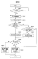
- the frequency information to be stored in the non-volatile memory 128 is limited, and it is difficult to obtain frequency information corresponding to any lens unit 200 from the non-volatile memory 128. Therefore, in the third embodiment of the present invention, when frequency information can not be obtained as a result, the function using the detection result of the shake detection unit 151 is prohibited or restricted.
- the present embodiment will be described using FIG. 8 in place of FIG. Similar to the second embodiment, the frequency information associated with the lens ID is stored in advance in, for example, the non-volatile memory 128.
- FIG. 8 is a flowchart of the function control process.
- the start conditions of the process of this flowchart are the same as the process of FIG.
- the system control unit 120 executes the same processing as steps S701 to S705 in FIG.
- the lens information acquired in step S 803 includes information indicating whether the drive frequency of the lens drive unit 204 can be acquired by communication.
- step S806 the system control unit 120 determines whether frequency information can be acquired from the imaging apparatus 100 based on the lens ID in the lens information.
- the system control unit 120 determines that the frequency information stored in the non-volatile memory 128 can be obtained if it corresponds to the acquired lens ID, and advances the process to step S807.
- the system control unit 120 determines that acquisition is not possible, and advances the process to step S809.
- step S807 the system control unit 120 executes the same process as step S706 in FIG. 7 and advances the process to step S808.
- steps S808 to S810 the system control unit 120 executes the same processing as steps S707 to S709 in FIG. 7 and ends the processing in FIG.
- step S806 the function restriction is also applied to the lens unit 200 in which the frequency information of the lens driving unit 204 is not stored in the non-volatile memory 128.
- the lens unit 200 which can not specify the frequency information is attached, it is unclear whether the drive frequency of the lens drive unit 204 interferes with the drive frequency of the shake detection unit 151. Therefore, it is because it is appropriate to prevent or limit the function uniformly in order to avoid the erroneous correction or the overcorrection.
- the first embodiment relates to avoiding improper execution of the function using the detection result of the shake detection unit 151 due to the frequency information on the lens unit 200. Similar effects can be achieved. In addition, when the frequency information can not be obtained, by prohibiting or restricting the above-mentioned function, it is not necessary to execute an inappropriate correction.
- a value obtained by inverting the output of the shake detection unit 151 is used as the correction amount, but the calculation method of the correction is not limited to the example.
- the frequency information corresponding to the lens ID is acquired from the non-volatile memory 128 in step S706 of FIG. 7 and step S807 of FIG.
- the determination in steps S707 and S808 may be performed based on the lens ID itself.
- the shake detection unit 151 which is an angular velocity sensor, is illustrated as a detection unit that detects shake of the imaging device 100.
- the detection unit is not limited to this.
- the shake may be detected from a motion vector acquired from a captured image.
- the image shake correction function and the follow shot imaging function are illustrated as the functions using the detection result of the shake detection unit 151, the functions are not limited to these.
- a drive frequency may be a target irrespective of a continuous drive frequency or an intermittent drive frequency.
- the lens unit 200 is illustrated as an accessory to be attached to and detached from the imaging apparatus 100, the accessory is not limited to this, and an accessory having a drive unit (for example, an outside having a zoom mechanism using a drive unit or a rotation mechanism Can be targeted if it is
- the present invention is also realized by performing the following processing. That is, software (program) for realizing the functions of the above-described embodiment is supplied to a system or apparatus via a network or various storage media, and a computer (or CPU, MPU or the like) of the system or apparatus reads out a program code. It is a process to execute. In this case, the program and the storage medium storing the program constitute the present invention.
Abstract
Provided is an imaging device in which an accessory such as a replacement lens can be detached, and which executes a function based on shaking. To avoid inappropriate execution of a function using the result of shake detection, which originates in frequency information pertaining to an accessory. When a lens unit 200 is mounted, a system control unit 120 acquires, through communication, frequency information indicating the drive frequency of a lens drive unit 204, and discerns whether there is interference between the drive frequency of the lens drive unit 204 indicated by the frequency information and the drive frequency of a shake detection unit 151 inside an imaging device 100. When there is no interference between the two drive frequencies, the system control unit 120 performs control in a normal manner without imposing an inhibition or a restriction on a function in which the shake detection unit 151 is used, e.g., an image shake correction function or a panning photograph function. When there is interference between the two drive frequencies, the system control unit 120 imposes an inhibition or a restriction on a function in which the shake detection unit 151 is used.
Description
本発明は、交換レンズ等のアクセサリを着脱可能であり、振れに基づく機能を実行する撮像装置等に関する。
The present invention relates to an imaging apparatus and the like that can be attached and detached with an accessory such as an interchangeable lens and that performs a function based on shake.
従来、交換レンズ等のアクセサリを着脱可能な撮像装置において、撮像装置本体の振れを検出し、検出した振れに基づいて像振れ補正等の機能を実行するカメラ等の撮像装置が知られている。例えば、手振れによる像振れの補正機能をもつ典型的な撮像装置では、手振れ量の検出に角速度センサ等の振れ検出センサが用いられている。検出した振れに基づいて、撮影光学系の一部或いは全部を駆動して結像面上の像振れ補正を行う。
2. Description of the Related Art Conventionally, among imaging devices in which accessories such as interchangeable lenses are removable, imaging devices such as cameras that detect shake of the imaging device body and execute functions such as image shake correction based on the detected shake are known. For example, in a typical imaging apparatus having a function of correcting image shake due to camera shake, a shake detection sensor such as an angular velocity sensor is used to detect the amount of camera shake. Based on the detected shake, a part or all of the photographing optical system is driven to perform image shake correction on the image forming surface.
しかし、撮像装置は、例えば、ミラーやシャッタ駆動部、レンズのピント制御を行う超音波モータやステッピングモータ等、様々な振動源を有している。振れ検出センサの感度は非常に敏感であるため、振れ検出センサの駆動周波数と近い周期で振動源による振動が発生した場合、振れ検出センサは振動の干渉を受けてしまう。すると、振れ検出センサの出力には、干渉によって発生するノイズ成分が重畳されてしまうため、適切な像振れ補正を行なえないという問題がある。そこで、特許文献1では、撮像装置が撮像部の読み出し周波数や駆動部の駆動周波数を変更したとき、振れ検出センサの駆動周波数を変更することで、撮像装置内で発生する振動やノイズによってセンサが干渉を受けることを回避している。
However, the imaging apparatus has various vibration sources such as, for example, a mirror and a shutter drive unit, an ultrasonic motor that performs focus control of a lens, and a stepping motor. Since the sensitivity of the shake detection sensor is very sensitive, the shake detection sensor is subject to vibration interference when vibration due to the vibration source occurs at a cycle close to the drive frequency of the shake detection sensor. Then, since the noise component generated by the interference is superimposed on the output of the shake detection sensor, there is a problem that appropriate image shake correction can not be performed. Therefore, in Patent Document 1, when the imaging device changes the reading frequency of the imaging unit or the driving frequency of the driving unit, the driving frequency of the shake detection sensor is changed to cause the sensor to generate vibration or noise in the imaging device. It avoids receiving interference.
しかしながら、交換レンズや外付けストロボなどのアクセサリを撮像装置に装着した場合、これらアクセサリにおける駆動部は、撮像装置から制御できない固有の駆動周波数で駆動される。そのため、装着したアクセサリで生じた振動によって、撮像装置内の振れ検出センサが干渉を受けてしまう場合がある。すなわち、アクセサリにおける駆動部の駆動周波数と振れ検出センサの駆動周波数とが干渉すると、適切な補正を行えず、誤補正や過補正となるおそれがある。また、アクセサリにおける駆動部の駆動周波数が撮像装置側で不明であるまま、振れ検出センサの出力に基づき振れ補正等の機能を実行した場合も、干渉により機能が適切に実行されないおそれがある。
However, when an accessory such as an interchangeable lens or an external flash is attached to the imaging device, the drive unit in these accessories is driven at a unique driving frequency that can not be controlled by the imaging device. Therefore, the shake detection sensor in the imaging device may be interfered by the vibration generated by the attached accessory. That is, when the drive frequency of the drive unit in the accessory and the drive frequency of the shake detection sensor interfere with each other, appropriate correction can not be performed, which may result in erroneous correction or over correction. In addition, even when a function such as shake correction is performed based on the output of the shake detection sensor while the drive frequency of the drive unit in the accessory is unknown on the imaging device side, the function may not be properly performed due to interference.
本発明は、アクセサリに関する周波数情報に起因して、振れ検出の結果を用いる機能が不適切に実行されることを回避することを目的とする。
An object of the present invention is to prevent inappropriate execution of a function using a result of shake detection due to frequency information on an accessory.
上記目的を達成するために、本発明は、撮像装置の振れを検出する検出手段と、前記撮像装置に装着されたアクセサリに関する周波数情報を取得する取得手段と、前記検出手段の検出結果を用いた機能を制御する制御手段と、を有し、前記制御手段は、前記取得手段により取得された周波数情報に基づいて、前記機能を制御することを特徴とする。
In order to achieve the above object, the present invention uses a detection unit that detects a shake of an imaging device, an acquisition unit that acquires frequency information on an accessory attached to the imaging device, and a detection result of the detection unit. And control means for controlling a function, wherein the control means controls the function based on frequency information acquired by the acquisition means.
本発明によれば、アクセサリに関する周波数情報に起因して、振れ検出の結果を用いる機能が不適切に実行されることを回避することができる。
According to the present invention, due to the frequency information on the accessory, it is possible to avoid that the function using the result of shake detection is performed improperly.
[図1]撮像装置を含むカメラシステムのブロック図である。
[図2]機能制御処理のフローチャートである。
[図3]像振れ補正における補正方向を説明する図である。
[図4A及び図4B]検出した振動量、像振れを補正するための補正量を示す図である。
[図5]駆動周波数の干渉の有無による像振れ補正機能の制御の態様を示す図である。
[図6]駆動周波数の干渉の有無による流し撮り撮影機能の制御の態様を示す図である。
[図7]機能制御処理のフローチャートである。
[図8]機能制御処理のフローチャートである。 FIG. 1 is a block diagram of a camera system including an imaging device.
FIG. 2 is a flowchart of function control processing.
FIG. 3 is a diagram for explaining a correction direction in image shake correction.
[FIG. 4A and FIG. 4B] It is a figure which shows the detected vibration amount and the correction amount for correct | amending image blurring.
FIG. 5 is a view showing an aspect of control of an image shake correction function according to the presence or absence of interference of a drive frequency.
FIG. 6 is a diagram showing an aspect of control of a follow shot photographing function according to the presence or absence of interference of a drive frequency.
FIG. 7 is a flowchart of function control processing.
FIG. 8 is a flowchart of function control processing.
以下、図面を参照して本発明の実施の形態を説明する。
Hereinafter, embodiments of the present invention will be described with reference to the drawings.
[第1の実施の形態]
図1は、本発明の第1の実施の形態に係る撮像装置を含むカメラシステムのブロック図である。このカメラシステムは、撮像装置100に、着脱可能な交換レンズであるレンズユニット200が装着されて構成される。 First Embodiment
FIG. 1 is a block diagram of a camera system including an imaging device according to a first embodiment of the present invention. This camera system is configured by mounting thelens unit 200, which is a removable interchangeable lens, on the imaging device 100.
図1は、本発明の第1の実施の形態に係る撮像装置を含むカメラシステムのブロック図である。このカメラシステムは、撮像装置100に、着脱可能な交換レンズであるレンズユニット200が装着されて構成される。 First Embodiment
FIG. 1 is a block diagram of a camera system including an imaging device according to a first embodiment of the present invention. This camera system is configured by mounting the
撮像装置100において、撮像素子121には、レンズ210、絞り211、レンズマウント102、202、シャッタ144を介して不図示の被写体の光学像が結像し、その光学像が電気信号に変換される。A/D変換部122は、撮像素子121の出力であるアナログ信号をデジタル信号に変換する。A/D変換部122でA/D変換されたデジタル信号は、メモリ制御部124及びシステム制御部120により制御され、メモリ127に格納される。
In the imaging device 100, an optical image of an object (not shown) is formed on the imaging element 121 via the lens 210, the aperture stop 211, the lens mounts 102 and 202, and the shutter 144, and the optical image is converted into an electrical signal. . The A / D converter 122 converts an analog signal output from the image sensor 121 into a digital signal. The digital signal A / D converted by the A / D conversion unit 122 is controlled by the memory control unit 124 and the system control unit 120, and is stored in the memory 127.
画像処理部123は、A/D変換部122でA/D変換されたデジタル信号のデータに対して所定の画素補間処理や色変換処理を行う。画像処理部123は、適応離散コサイン変換(ADCT)等により画像データを圧縮伸長する圧縮・伸長回路も備える。画像処理部123は、メモリ127に格納された画像を読み込んで圧縮処理或いは伸長処理を行い、処理を終えたデータをメモリ127に書き込むことも可能である。画像演算部129は、撮像画像のコントラスト値を算出し、コントラスト値から撮影画像の合焦状態を測定することができ、メモリ127に格納された画像データと現在の撮像画像の相関値を算出し、最も相関の高い領域を探索することも可能である。
The image processing unit 123 performs predetermined pixel interpolation processing and color conversion processing on the digital signal data A / D converted by the A / D conversion unit 122. The image processing unit 123 also includes a compression / decompression circuit that compresses / decompresses image data by adaptive discrete cosine transform (ADCT) or the like. The image processing unit 123 can also read an image stored in the memory 127, perform compression processing or decompression processing, and write the processed data to the memory 127. The image operation unit 129 can calculate the contrast value of the captured image, measure the in-focus state of the captured image from the contrast value, and calculate the correlation value between the image data stored in the memory 127 and the current captured image. It is also possible to search for the area with the highest correlation.
メモリ制御部124は、A/D変換部122、画像処理部123、表示装置110及び外部着脱メモリ部130とメモリ127との間のデータの送受を制御する。A/D変換部122のデータが画像処理部123を介して、メモリ127に書き込まれる。表示装置110は、不図示の液晶パネル表示部、バックライト照明部により構成され、撮像素子121から得られた撮像データを逐次リアルタイムにスルー画像表示することでライブビュー撮影を可能とする。ライブビュー撮影中は、AF対象の被写体の位置を操作者が認識できるよう、表示装置110に、AF領域を示すAF枠が画像に重畳して表示可能である。
The memory control unit 124 controls transmission and reception of data between the A / D conversion unit 122, the image processing unit 123, the display device 110, the external removable memory unit 130, and the memory 127. The data of the A / D conversion unit 122 is written to the memory 127 via the image processing unit 123. The display device 110 includes a liquid crystal panel display unit and a backlight illumination unit (not shown), and enables live view shooting by sequentially displaying live image data of imaging data obtained from the imaging device 121 in real time. During live view shooting, an AF frame indicating an AF area can be superimposed on an image and displayed on the display device 110 so that the operator can recognize the position of a subject to be subjected to AF.
システム制御部120は撮像装置100全体を制御し、インターフェース101、201を介してレンズ制御部203を制御することでレンズユニット200を制御することも可能である。メモリ127は、撮影された静止画像及び動画像、再生用表示のための画像のデータを格納できる。なお、メモリ127には、システム制御部120のプログラムスタック領域、ステータス記憶領域、演算用領域、ワーク用領域、画像表示データ用領域が確保されている。各種の演算は、メモリ127の演算用領域を利用し、システム制御部120により実行される。
The system control unit 120 can control the entire imaging apparatus 100 and can control the lens unit 200 by controlling the lens control unit 203 via the interfaces 101 and 201. The memory 127 can store data of photographed still images and moving images, and images for display for reproduction. In the memory 127, a program stack area, a status storage area, an operation area, a work area, and an image display data area of the system control unit 120 are secured. Various operations are performed by the system control unit 120 using the operation area of the memory 127.
不揮発性メモリ128は電気的に消去・記録可能なメモリで、例えばフラッシュメモリやEEPROM等が用いられる。不揮発性メモリ128には、撮影状態を示す情報や、撮像装置100を制御するプログラム等が格納されている。外部着脱メモリ部130は、コンパクトフラッシュ(登録商標)やSDカードといった記録媒体に対して画像ファイル記録や読出を行う。電源部131は、電池、電池検出回路、DC−DCコンバータ、通電するブロックを切り替えるスイッチ回路等により構成され、電池の装着の有無、電池の種類、電池残量を検出する。また、電源部131は、検出結果及びシステム制御部120の指示に基づいてDC−DCコンバータを制御し、必要な電圧を必要な期間、各ブロック部へ供給する。
The non-volatile memory 128 is an electrically erasable / recordable memory, and for example, a flash memory or an EEPROM is used. The non-volatile memory 128 stores information indicating a photographing state, a program for controlling the imaging device 100, and the like. The external removable memory unit 130 performs image file recording and reading on a recording medium such as a Compact Flash (registered trademark) or an SD card. The power supply unit 131 includes a battery, a battery detection circuit, a DC-DC converter, a switch circuit for switching a block to be energized, and the like, and detects the presence or absence of a battery, the type of battery, and the battery remaining amount. Further, the power supply unit 131 controls the DC-DC converter based on the detection result and the instruction of the system control unit 120, and supplies the necessary voltage to each block for a necessary period.
シャッタ制御部141は、測光部142からの測光情報に基づいて、絞り211を制御するレンズ制御部203と連携しながらシャッタ144を制御する。測光部142はAE(自動露出)処理を行う。レンズ210に入射した光線が、絞り211、レンズマウント202、102、さらには不図示の測光用レンズを介して測光部142に入射することにより、光学像として結像された画像の露出状態が測定可能となる。また、測光部142は、ストロボユニット300と連携することによりEF(フラッシュ調光)処理機能も備える。また、ストロボユニット300は、AF補助光の投光機能、フラッシュ調光機能も備える。
The shutter control unit 141 controls the shutter 144 in cooperation with the lens control unit 203 that controls the diaphragm 211 based on the photometric information from the photometric unit 142. A photometry unit 142 performs an AE (automatic exposure) process. The light beam incident on the lens 210 is incident on the photometric unit 142 through the aperture stop 211, the lens mounts 202 and 102, and the photometric lens (not shown), whereby the exposure state of the image formed as an optical image is measured. It becomes possible. The photometry unit 142 also has an EF (flash light control) processing function by cooperating with the flash unit 300. The flash unit 300 also has a light emission function of AF auxiliary light and a flash light control function.
測距部143はAF処理を行う。レンズ210に入射した光線が、絞り211、レンズマウント202、102、さらには不図示の測距用ミラーを介して測距部143に入射することにより、光学像として結像された画像の合焦状態が測定可能となる。尚、測距部143は、ライブビュー撮影中は、画像演算部129より出力された画像データから求められたコントラスト値に応じて、撮影画像の合焦状態を測定することも可能である。シャッタ144は、非撮影時には撮像素子121を遮光し、撮影時には開いて撮像素子121へ光線を導く。操作部132は、システム制御部120の各種の動作指示を入力するための操作部である。操作部132は、スイッチやダイヤル、視線検知によるポインティング、音声認識装置等の単数或いは複数の組み合わせで構成される。振れ検出部151は、例えば角速度センサなどで構成され、撮像装置100の内部の振動量を検出する検出手段である。振れ検出部151は、図3に示すように、Pitch方向、Yaw方向、Roll方向の3軸方向の振動を検出できる。
The distance measuring unit 143 performs an AF process. A light beam incident on the lens 210 is incident on the distance measuring unit 143 via the aperture stop 211, the lens mounts 202 and 102, and a distance measuring mirror (not shown) to focus the image formed as an optical image. The state can be measured. During live view shooting, the distance measuring unit 143 can also measure the in-focus state of the shot image according to the contrast value obtained from the image data output from the image calculation unit 129. The shutter 144 shields the imaging element 121 from light when not photographing, and opens to guide a light beam to the imaging element 121 during photographing. The operation unit 132 is an operation unit for inputting various operation instructions of the system control unit 120. The operation unit 132 is configured of a single switch or a combination of a switch, a dial, pointing by sight detection, a voice recognition device, and the like. The shake detection unit 151 is, for example, an angular velocity sensor, and is a detection unit that detects an amount of vibration inside the imaging device 100. The shake detecting unit 151 can detect vibrations in three axial directions, that is, the pitch direction, the yaw direction, and the roll direction, as shown in FIG.
レンズマウント102及びレンズマウント202は、撮像装置100をレンズユニット200と接続するための機械的な保持機構である。レンズマウント102、202は、撮像装置100をレンズユニット200と電気的に接続する接続端子を有し、システム制御部120は接続端子を介してレンズ制御部203と通信を行う。アクセサリシュー111、301は、撮像装置100にストロボユニット300を接続するためのインターフェースである。レンズユニット200は、不図示の被写体の光学像を、レンズ210から絞り211、レンズマウント202、102及びシャッタ144を介して導き、撮像素子121上に結像させることができる。
The lens mount 102 and the lens mount 202 are mechanical holding mechanisms for connecting the imaging device 100 to the lens unit 200. The lens mounts 102 and 202 have connection terminals for electrically connecting the imaging device 100 to the lens unit 200, and the system control unit 120 communicates with the lens control unit 203 via the connection terminals. The accessory shoes 111 and 301 are interfaces for connecting the flash unit 300 to the imaging device 100. The lens unit 200 can guide an optical image of an object (not shown) from the lens 210 through the aperture stop 211, the lens mounts 202 and 102, and the shutter 144, and form an image on the imaging device 121.
レンズ制御部203はレンズユニット200全体を制御する。レンズ制御部203は不揮発メモリの機能も備える。この不揮発メモリには、動作用の定数、変数、プログラム等を記憶するメモリやレンズユニット200固有の番号等の識別情報(レンズID)、管理情報、開放絞り値や最小絞り値、焦点距離等の機能情報、現在や過去の各設定値が記憶される。さらに、レンズ制御部203の不揮発メモリには、レンズ駆動部204の駆動周波数等を示す「周波数情報」が保持される。レンズ制御部203は、測距部143或いは画像処理部123より測定された画像の合焦状態に応じて、レンズ210のフォーカシングを制御し、撮像素子121に入射する被写体像の結像位置を変更することでAF動作を行える。また、レンズ制御部203は絞り211の制御や、レンズ210のズーミングを制御する機能も兼ね備える。
The lens control unit 203 controls the entire lens unit 200. The lens control unit 203 also has a non-volatile memory function. In this non-volatile memory, memory for storing operation constants, variables, programs etc., identification information (lens ID) such as number unique to the lens unit 200, management information, open aperture value, minimum aperture value, focal distance etc. Function information and current and past setting values are stored. Further, “non-volatile memory” of the lens control unit 203 holds “frequency information” indicating a drive frequency of the lens drive unit 204 and the like. The lens control unit 203 controls focusing of the lens 210 according to the focusing state of the image measured by the distance measuring unit 143 or the image processing unit 123, and changes the imaging position of the subject image incident on the imaging element 121. The AF operation can be performed by doing this. The lens control unit 203 also has a function of controlling the diaphragm 211 and controlling the zooming of the lens 210.
レンズ駆動部204はレンズ210及び絞り211を駆動する。レンズ駆動部204は、レンズ制御部203からのフォーカシング制御信号、ズーミング制御信号、像振れ補正制御信号を受けてレンズ210を駆動する。さらに、レンズ駆動部204は、絞り制御信号を受けて絞り211を駆動する。レンズ駆動部204は上記のフォーカシング制御機構、ズーミング制御機構、像ぶれ補正制御機構、絞り制御機構をそれぞれ備えている。振れ検出部205は、例えばジャイロセンサなどで構成され、レンズユニット200の内部の振動量を検出する。振れ検出部205は、Pitch方向、Yaw方向、Roll方向のうち、Pitch方向とYaw方向の2軸方向の振動を検出できる。
The lens drive unit 204 drives the lens 210 and the aperture 211. The lens driving unit 204 receives the focusing control signal, the zooming control signal, and the image blur correction control signal from the lens control unit 203, and drives the lens 210. Further, the lens drive unit 204 receives the diaphragm control signal to drive the diaphragm 211. The lens drive unit 204 includes the focusing control mechanism, the zooming control mechanism, the image blur correction control mechanism, and the aperture control mechanism described above. The shake detection unit 205 includes, for example, a gyro sensor, and detects an amount of vibration inside the lens unit 200. The shake detection unit 205 can detect vibration in two axial directions, the Pitch direction and the Yaw direction, among the Pitch direction, the Yaw direction, and the Roll direction.
ストロボユニット300は、アクセサリシュー111に接続可能である。インターフェース301は、アクセサリシュー111内において、ストロボユニット300と撮像装置100と電気的に接続する。ストロボ発光制御部302はストロボユニット300全体を制御し、不図示のキセノン管等の発光部に対し、測光部142からの情報に基づいて発光量や発光タイミングを制御する。
The strobe unit 300 can be connected to the accessory shoe 111. The interface 301 electrically connects the flash unit 300 and the imaging apparatus 100 in the accessory shoe 111. The flash control unit 302 controls the entire flash unit 300, and controls the amount and timing of light emission based on the information from the light measuring unit 142 with respect to a light emitting unit such as a xenon tube (not shown).
振れ検出部151の検出結果を用いてシステム制御部120が実現する機能として、本実施の形態では像振れ補正及び流し撮り撮影機能を例示する。流し撮り撮影機能は、移動する被写体の動きに追従しながら撮影する機能であり、像振れ補正機能を応用することで被写体のぶれを抑え、背景を流した撮影を可能にする。図2~図6で詳細に説明するように、システム制御部120は、レンズユニット200の周波数情報を取得し、取得された周波数情報に基づいて、上記機能を制御する。具体的には、装着されたレンズユニット200の周波数情報によって撮像装置100の像ぶれ補正の制御の態様を変更する。
As a function realized by the system control unit 120 using the detection result of the shake detection unit 151, an image shake correction function and a follow shot photographing function are illustrated in the present embodiment. The follow shot shooting function is a function of shooting while following the movement of a moving subject, and by applying the image blur correction function, it is possible to suppress the shake of the subject and enable shooting with a background. As described in detail with reference to FIGS. 2 to 6, the system control unit 120 acquires frequency information of the lens unit 200, and controls the above-described function based on the acquired frequency information. Specifically, the control mode of the image blurring correction of the imaging device 100 is changed according to the frequency information of the lens unit 200 mounted.
図2は、機能制御処理のフローチャートである。このフローチャートの処理は、不揮発性メモリ128に格納されたプログラムをシステム制御部120がメモリ127に展開して実行することにより実現される。この処理は、撮像装置100の電源がオンとなったとき、またはオンの状態で操作部132が操作されると開始される。この処理において、システム制御部120は、本発明における制御手段、取得手段に該当する。
FIG. 2 is a flowchart of the function control process. The processing of this flowchart is realized by the system control unit 120 developing the program stored in the non-volatile memory 128 in the memory 127 and executing the program. This process is started when the power of the imaging apparatus 100 is turned on or when the operation unit 132 is operated in the on state. In this process, the system control unit 120 corresponds to control means and acquisition means in the present invention.
まず、ステップS201では、システム制御部120は、レンズマウント202、102を介してレンズユニット200が撮像装置100に装着されているか否かを判別し、装着されるまで判別を継続する。そして、レンズユニット200が装着されると、ステップS202で、システム制御部120は、装着されたレンズユニット200のレンズ制御部203との通信を開始する。ステップS203で、システム制御部120は、装着されたレンズユニット200を特定するためのレンズ情報をレンズ制御部203から通信にて取得する。このレンズ情報には例えば、レンズIDやレンズによる固有の光学的補正値情報等が含まれる。ステップS204では、システム制御部120は、レンズ駆動部204の駆動周波数を示す周波数情報を通信にて取得する。
First, in step S201, the system control unit 120 determines whether the lens unit 200 is attached to the imaging apparatus 100 via the lens mounts 202 and 102, and continues the determination until the lens unit 200 is attached. When the lens unit 200 is attached, the system control unit 120 starts communication with the lens control unit 203 of the attached lens unit 200 in step S202. In step S203, the system control unit 120 acquires lens information for specifying the attached lens unit 200 from the lens control unit 203 by communication. The lens information includes, for example, a lens ID and optical correction value information unique to the lens. In step S204, the system control unit 120 acquires frequency information indicating the drive frequency of the lens drive unit 204 by communication.
ステップS205では、システム制御部120は、ステップS204で取得した周波数情報が示すレンズ駆動部204の駆動周波数と、撮像装置100の内部の振れ検出部151の駆動周波数とが干渉するか否かを判別する。例えば、両者の比または差が所定以内であるとき、干渉すると判別される。その判別の結果、レンズ駆動部204と振れ検出部151の両者間で駆動周波数の干渉が無い場合は、ステップS207へ進み、両者間で駆動周波数の干渉が有る場合は、ステップS206へ進む。ステップS206、S207の後、図2の処理は終了する。
In step S205, the system control unit 120 determines whether the drive frequency of the lens drive unit 204 indicated by the frequency information acquired in step S204 interferes with the drive frequency of the shake detection unit 151 in the imaging device 100. Do. For example, when the ratio or difference between the two is within a predetermined range, it is determined that interference occurs. As a result of the determination, if there is no interference of the drive frequency between both the lens drive unit 204 and the shake detection unit 151, the process proceeds to step S207. If there is interference of the drive frequency between the both, the process proceeds to step S206. After steps S206 and S207, the process of FIG. 2 ends.
ステップS207では、システム制御部120が振れ検出部151を用いた機能、例えば像振れ補正機能や流し撮り撮影機能に対して禁止や制限をかけずに通常通りに制御する。一方、ステップS206では、システム制御部120は、振れ検出部151を用いた機能に対して禁止等の制限をかける。
In step S207, the system control unit 120 normally controls the function using the shake detection unit 151, for example, the image shake correction function and the follow shot photographing function without prohibiting or restricting. On the other hand, in step S206, the system control unit 120 restricts the function using the shake detection unit 151 such as prohibition.
ここで、振れ検出部151を用いた機能のうち像振れ補正機能に対する処理について説明する。図3は、撮像装置100の像振れ補正における補正方向を説明する図である。振れ検出部151により検出される手振れ等の振動方向は、撮像装置100について、Pitch方向、Yaw方向、Roll方向の、互いに直交する3軸方向からなる。Roll方向は、撮影光軸回り(撮像面が光軸に垂直な面内で回転する方向)である。Pitch方向は水平面に対する傾動方向(チルティング方向)である。Yaw方向は鉛直面に対する傾動方向(パンニング方向)である。これらは互いに直交する。
Here, among the functions using the shake detection unit 151, processing for the image shake correction function will be described. FIG. 3 is a diagram for explaining a correction direction in image shake correction of the imaging device 100. The vibration directions of camera shake or the like detected by the shake detection unit 151 are three axial directions orthogonal to each other in the pitch direction, the Yaw direction, and the Roll direction. The Roll direction is around the photographing optical axis (the direction in which the imaging surface rotates in a plane perpendicular to the optical axis). The Pitch direction is the tilting direction (tilting direction) with respect to the horizontal plane. The yaw direction is the tilting direction (panning direction) with respect to the vertical plane. These are orthogonal to one another.
像振れ補正機能には、レンズ防振(光学補正)、センサ防振(光学補正)、電子防振(読み出し範囲移動)が採用され得る。例えば、検出された上記各方向の振動に応じた、レンズ制御部203が行う光学的な補正や、撮像素子121で読みだした撮影画像に対してシステム制御部120が行う電子的な補正によって、撮像装置100の像振れ補正機能は実現される。レンズ制御部203による光学的な補正はPitch方向とYaw方向について行える。システム制御部120が行う電子的な補正は通常、Roll方向について行われる。なお、レンズユニット200には光学的な補正をする仕組みがないものもある。そのようなレンズユニット200が装着された場合は、システム制御部120はRoll方向だけでなくPitch方向及びYaw方向についての補正も電子的に行う。
Lens image stabilization (optical correction), sensor image stabilization (optical correction), and electronic image stabilization (reading range movement) may be adopted as the image shake correction function. For example, optical correction performed by the lens control unit 203 according to the detected vibration in each direction, or electronic correction performed by the system control unit 120 on a captured image read by the imaging device 121 The image blur correction function of the imaging device 100 is realized. Optical correction by the lens control unit 203 can be performed in the Pitch direction and the Yaw direction. The electronic correction performed by the system control unit 120 is usually performed in the Roll direction. Some lens units 200 do not have an optical correction mechanism. When such a lens unit 200 is attached, the system control unit 120 electronically performs correction not only in the Roll direction but also in the Pitch direction and the Yaw direction.
図4Aは、検出した振動量を示す図である。図4Bは、振動量に対応して像振れを補正するための補正量を示す図である。図4Aに示す振動量は、撮像装置100の振れ検出部151の出力、レンズユニット200の振れ検出部205の出力のいずれであってもよいが、ここでは振れ検出部151の出力として説明する。また、振れ補正を行う主体はシステム制御部120、レンズ制御部203のいずれでもよいが、ここではシステム制御部120として説明する。
FIG. 4A is a diagram showing the detected amount of vibration. FIG. 4B is a diagram showing a correction amount for correcting the image blur in accordance with the vibration amount. The vibration amount shown in FIG. 4A may be either the output of the shake detection unit 151 of the imaging device 100 or the output of the shake detection unit 205 of the lens unit 200, but here, the output is the shake detection unit 151. Further, although the main body of performing the shake correction may be either the system control unit 120 or the lens control unit 203, the system control unit 120 will be described here.
振れ検出部151が振動を検出し、その検出結果である振動量をシステム制御部120にアナログ信号もしくはデジタルデータとして送信する。システム制御部120は、受信した振動量のデータから補正量を算出する。例えば、像振れ補正機能を制限せずに、単純に振動を打ち消すための演算をするのであれば、システム制御部120は、図4Bに実線で示すように、図4Aの振動量を反転させた通常時の補正量を算出し、像振れ補正機能を制御する。また、像振れ補正機能を制限する場合は、システム制御部120は、図4Bに点線で示すように、通常時の補正量を半減させた制限時の補正量を算出し、像振れ補正機能を制御する。
The shake detecting unit 151 detects a vibration, and transmits a vibration amount as a detection result to the system control unit 120 as an analog signal or digital data. The system control unit 120 calculates the correction amount from the received data of the vibration amount. For example, if calculation is simply performed to cancel the vibration without limiting the image blur correction function, the system control unit 120 inverts the vibration amount of FIG. 4A as shown by a solid line in FIG. 4B. The correction amount at the normal time is calculated, and the image blur correction function is controlled. In addition, when limiting the image blur correction function, the system control unit 120 calculates the correction amount at the time of limitation by halving the correction amount at the normal time, as shown by a dotted line in FIG. Control.
像振れ補正機能の制御に関し、図2のステップS207では、システム制御部120は、例えば図3に示す3つ全ての方向で補正を許可する。ステップS206における機能の制限では、例えば図4Bに点線で示すように補正量を減少させる(例えば、半減)。あるいは、補正量を零とするかまたは、像振れ補正機能それ自体を行わない(禁止する)。
Regarding control of the image shake correction function, in step S207 of FIG. 2, the system control unit 120 permits correction in all three directions shown in FIG. 3, for example. In the function limitation in step S206, for example, the correction amount is reduced (for example, halved) as indicated by a dotted line in FIG. 4B. Alternatively, the correction amount is set to zero or the image blur correction function itself is not performed (prohibited).
図5は、レンズ駆動部204と振れ検出部151の両者間での駆動周波数の干渉の有無による像振れ補正機能の制御の態様を示す図である。振れ検出部151の駆動周波数と干渉するレンズ駆動部204を有する「干渉するレンズ」と、そうでない「干渉しないレンズ」とで、像振れ補正機能の許否の態様が異なる。また、レンズユニット200が像振れ補正機能を有しているか(IS対応レンズか)否か、さらには振れの方向によっても像振れ補正機能の許否の態様が異なる。
FIG. 5 is a diagram showing an aspect of control of the image shake correction function based on the presence or absence of the interference of the drive frequency between both the lens drive unit 204 and the shake detection unit 151. As shown in FIG. The mode of permission of the image blur correction function differs between the “interfering lens” having the lens driving unit 204 that interferes with the drive frequency of the shake detection unit 151 and the “non-interference lens” that does not. In addition, whether or not the lens unit 200 has an image blur correction function (is an IS compatible lens), and also the manner of permission or rejection of the image blur correction function differs depending on the direction of the shake.
具体的には、干渉しないレンズについては、従来と同様に、システム制御部120は、撮像装置100による3方向についての像振れ補正機能を禁止や制限することなく許可する。また、システム制御部120は、干渉しないレンズであって像振れ補正機能を有するレンズユニット200に対しては、レンズ制御部203によるPitch方向及びYaw方向の補正を許可する。一方、干渉するレンズについては、システム制御部120は、撮像装置100による3方向についての像振れ補正機能を禁止または制限する。ここで、振れ検出部205の検出結果に基づきレンズ制御部203が行うPitch方向及びYaw方向の補正については、上記干渉による影響を受けない。そこで、システム制御部120は、干渉するレンズであって像振れ補正機能を有するレンズユニット200に対しては、レンズ制御部203によるPitch方向及びYaw方向の振れ補正を許可する。従って、レンズ制御部203がPitch方向とYaw方向に対して行う光学的な補正は制限されることなく許可されることになる。
Specifically, with respect to lenses that do not interfere, the system control unit 120 permits the image blur correction function in three directions by the imaging device 100 without prohibiting or restricting the same as in the related art. Further, the system control unit 120 permits the lens control unit 203 to perform correction in the Pitch direction and the Yaw direction with respect to the lens unit 200 that does not interfere and has an image blur correction function. On the other hand, with respect to the interfering lenses, the system control unit 120 prohibits or restricts the image blur correction function in three directions by the imaging device 100. Here, the correction in the Pitch direction and the Yaw direction performed by the lens control unit 203 based on the detection result of the shake detection unit 205 is not affected by the interference. Therefore, the system control unit 120 permits the lens control unit 203 to perform shake correction in the Pitch direction and the Yaw direction with respect to the lens unit 200 that is an interfering lens and has an image shake correction function. Therefore, the optical correction that the lens control unit 203 performs in the Pitch direction and the Yaw direction is permitted without limitation.
また、流し撮り撮影機能の制御については次のようになる。図6は、駆動周波数の干渉の有無による流し撮り撮影機能の制御の態様を示す図である。干渉するレンズと干渉しないレンズとで、流し撮り撮影機能の許否の態様が異なる。流し撮り撮影においては、振れ検出部151が検出した撮像装置100のパンニング角速度と撮影画像からシステム制御部120が取得した被写体の角速度との差分量に基づいて像振れが補正される。システム制御部120は、パンニング角速度と被写体の移動量とから、背景の流れ度合いに応じてシャッタスピードを制御することで、適切な背景流れを実現できる。通常、背景の流れ度合いは、例えば、ユーザの好みに応じて図6に示すように3段階で設定可能である。すなわち、背景の流れ度合いが「大」、「標準:中」、「小」と、適用可能なモード数が3つ存在する。表示装置110に設定画面を表示することでユーザが背景の流れ度合いを設定することもできる。
Also, the control of the panning photography function is as follows. FIG. 6 is a diagram showing an aspect of control of the follow shot photographing function according to the presence or absence of interference of the drive frequency. The mode of permission of the follow shot photographing function differs depending on the interfering lens and the non-interfering lens. In the follow shot shooting, the image shake is corrected based on the difference between the panning angular velocity of the imaging device 100 detected by the shake detection unit 151 and the angular velocity of the subject acquired by the system control unit 120 from the photographed image. The system control unit 120 can realize an appropriate background flow by controlling the shutter speed in accordance with the flow degree of the background from the panning angular velocity and the movement amount of the subject. Usually, the background flow degree can be set, for example, in three stages as shown in FIG. 6 according to the preference of the user. That is, there are three possible modes with the background flow degree being "large", "standard: medium", and "small". By displaying the setting screen on the display device 110, the user can also set the background flow degree.
流し撮り撮影機能の制御に関し、システム制御部120は、干渉しないレンズの場合、3つのモード全てについて、禁止や制限することなく適用可能と(許可)する。従って、背景の流れ度合いの設定は3段階で対応することができる。一方、干渉するレンズの場合は、システム制御部120は、流し撮り撮影機能の背景の流れ度合いは標準設定しか対応しないように制限を加える。このように適用可能なモード数を削減するのは、期待した流れ効果が得られなかったり、逆に流れ効果が大き過ぎたりすることを回避するためである。
In the case of a non-interfering lens, the system control unit 120 applies (permits) all three modes without prohibiting or restricting the control of the follow shot imaging function. Therefore, setting of the background flow degree can be handled in three steps. On the other hand, in the case of an interfering lens, the system control unit 120 limits the flow degree of the background of the follow shot photographing function so as to correspond to only the standard setting. The reason for reducing the number of applicable modes in this way is to prevent the expected flow effect from being obtained or the flow effect from becoming too large.
なお、撮像装置100が起動している状態でレンズユニット200が交換された場合、図2の処理が再び開始されることで、新たなレンズユニット200に応じて、機能が制限されたり制限が解除されたりする。
In addition, when the lens unit 200 is replaced in a state where the imaging device 100 is activated, the processing in FIG. 2 is started again, whereby the function is restricted or the restriction is released according to the new lens unit 200. Be done.
このように、システム制御部120は、レンズ駆動部204の駆動周波数が振れ検出部151の駆動周波数と干渉する場合に、振れ検出部151の検出結果を使用した機能を禁止したり制限をかけたりする。これにより、レンズユニット200から受ける振動によるノイズの影響を抑えることができる。
As described above, when the drive frequency of the lens drive unit 204 interferes with the drive frequency of the shake detection unit 151, the system control unit 120 prohibits or limits the function using the detection result of the shake detection unit 151. Do. Thereby, the influence of the noise due to the vibration received from the lens unit 200 can be suppressed.
本実施の形態によれば、装着されたレンズユニット200から取得された周波数情報に基づいて、振れ検出部151の検出結果を用いる機能が制御される。これにより、レンズユニット200に関する周波数情報に起因して上記機能が不適切に実行されることを回避することができる。特に、レンズ駆動部204の駆動周波数と振れ検出部151の駆動周波数との干渉が有る場合は上記機能が禁止または制限されるので、誤補正や過補正を回避できる。一方、上記干渉が無い場合は、上記機能が禁止または制限されることなく許可されるので、本来の制御により上記機能が十分に果たされる。
According to the present embodiment, the function of using the detection result of the shake detection unit 151 is controlled based on the frequency information acquired from the mounted lens unit 200. Thereby, it can be avoided that the above function is improperly executed due to the frequency information on the lens unit 200. In particular, when there is interference between the drive frequency of the lens drive unit 204 and the drive frequency of the shake detection unit 151, the above function is prohibited or limited, so that erroneous correction or overcorrection can be avoided. On the other hand, when the interference does not occur, the function is permitted without being prohibited or restricted, so that the function is sufficiently performed by the original control.
また、像振れ補正機能を制限する場合に、通常時に比べ補正量を半減させるので、誤補正や過補正となる場合であってもその程度を緩和することができる。なおこの観点からは、上記干渉が無い場合の制御に比べて補正の度合いを小さくすればよく、半減に限定されない。また、流し撮り撮影機能を制限する場合に、対応する背景の流れ度合いの設定段階を1段階とするので、誤補正や過補正を回避できる。なおこの観点からは、上記機能を制限する場合に、上記干渉が無い場合の制御に比べて、適用するモード数を少なくするようにしてもよい。
In addition, when the image blur correction function is limited, the correction amount is reduced by half as compared to that in the normal case, so that the degree can be mitigated even in the case of erroneous correction or over correction. From this point of view, the degree of correction may be made smaller than the control in the case where there is no interference, and it is not limited to half. In addition, since the setting step of the corresponding background flow degree is set to one step when restricting the follow shot photographing function, erroneous correction and over correction can be avoided. From this point of view, when limiting the function, the number of modes to be applied may be reduced as compared with the control in the absence of the interference.
また、撮像装置100での像振れ補正機能が制限される場合であっても、レンズユニット200が有する振れ検出部205の検出結果を用いて像振れ補正機能がレンズユニット200により制御されることは許可される。これにより、レンズユニット200による機能制御を無駄にすることがない。
Further, even when the image blur correction function in the imaging apparatus 100 is limited, the image blur correction function is controlled by the lens unit 200 using the detection result of the blur detection unit 205 of the lens unit 200. Permitted. Thereby, the function control by the lens unit 200 is not wasted.
[第2の実施の形態]
上記第1の実施の形態では、システム制御部120は、周波数情報を通信にて直接取得した。しかし、常に周波数情報を通信にて直接取得できるとは限らない。そこで、本発明の第2の実施の形態では、周波数情報を通信にて直接取得できたか否かによって制御を分ける。第1の実施の形態に対して、図2に代えて図7を用いて本実施の形態を説明する。 Second Embodiment
In the first embodiment, the system control unit 120 directly acquires frequency information by communication. However, frequency information can not always be obtained directly by communication. Therefore, in the second embodiment of the present invention, control is divided depending on whether or not frequency information can be directly obtained by communication. This embodiment will be described using FIG. 7 instead of FIG. 2 with respect to the first embodiment.
図7は、機能制御処理のフローチャートである。このフローチャートの処理の開始条件は図2の処理と同様である。システム制御部120は、ステップS701~S703では、図2のステップS201~S203と同様の処理を実行する。ただし、ステップS703で取得されるレンズ情報には、レンズ駆動部204の駆動周波数を通信で取得できるかどうかを示す情報が含まれるとする。
FIG. 7 is a flowchart of the function control process. The start condition of the process of this flowchart is the same as the process of FIG. At steps S701 to S703, the system control unit 120 executes the same processing as steps S201 to S203 of FIG. However, it is assumed that the lens information acquired in step S703 includes information indicating whether or not the drive frequency of the lens drive unit 204 can be acquired by communication.
ステップS704では、システム制御部120は、取得したレンズ情報に基づき、装着されたレンズユニット200のレンズ駆動部204の駆動周波数を通信にて取得できるか否かを判別する。そしてシステム制御部120は、駆動周波数を通信にて取得できると判別した場合は処理をステップS705へ進め、取得できないと判別した場合は処理をステップS706へ進める。システム制御部120は、ステップS705では、図2のステップS204と同様の処理により周波数情報を通信にて取得する。その後、処理はステップS707へ進む。
In step S704, the system control unit 120 determines, based on the acquired lens information, whether the drive frequency of the lens driving unit 204 of the mounted lens unit 200 can be acquired by communication. Then, if the system control unit 120 determines that the drive frequency can be acquired by communication, the process proceeds to step S705, and if it is determined that the drive frequency can not be acquired, the process proceeds to step S706. In step S705, the system control unit 120 acquires frequency information through communication by the same processing as step S204 in FIG. Thereafter, the processing proceeds to step S 707.
ステップS706では、システム制御部120は、レンズ情報のレンズIDに基づいて周波数情報を撮像装置100から取得する。具体的には、予め、レンズIDに関連付けした周波数情報を、記憶部、例えば不揮発性メモリ128に記憶させておく。システム制御部120は、不揮発性メモリ128に記憶された周波数情報のうち、取得したレンズIDに対応するものを、装着されているレンズユニット200のレンズ駆動部204の周波数情報として取得する。これにより、システム制御部120は、周波数情報を通信にて取得できないレンズユニット200であっても、レンズ駆動部204の周波数情報の取得が可能となる。その後、処理はステップS707へ進む。
In step S706, the system control unit 120 acquires frequency information from the imaging apparatus 100 based on the lens ID of the lens information. Specifically, frequency information associated with the lens ID is stored in advance in a storage unit, for example, the non-volatile memory 128. The system control unit 120 acquires, among the frequency information stored in the non-volatile memory 128, one corresponding to the acquired lens ID as frequency information of the lens driving unit 204 of the lens unit 200 mounted. As a result, the system control unit 120 can acquire frequency information of the lens drive unit 204 even if the lens unit 200 can not acquire frequency information by communication. Thereafter, the processing proceeds to step S 707.
ステップS707~S709では、システム制御部120は、図2のステップS205~S207と同様の処理を実行し、図7の処理を終了させる。
In steps S707 to S709, the system control unit 120 executes the same processing as in steps S205 to S207 in FIG. 2, and ends the processing in FIG.
本実施の形態によれば、レンズユニット200に関する周波数情報に起因して、振れ検出部151の検出結果を用いる機能が不適切に実行されることを回避することに関し、第1の実施の形態と同様の効果を奏することができる。
According to the present embodiment, the first embodiment relates to avoiding improper execution of the function using the detection result of the shake detection unit 151 due to the frequency information on the lens unit 200. Similar effects can be achieved.
また、通信によって周波数情報を取得できないようなレンズユニット200が装着された場合であっても、その周波数情報を取得できる。従って、振れ検出部151の駆動周波数と干渉するかどうかの判別が可能となり、上記機能の適切な制御が可能となる。
Further, even when the lens unit 200 is mounted such that frequency information can not be obtained by communication, the frequency information can be obtained. Therefore, it is possible to determine whether or not the drive frequency of the shake detection unit 151 interferes, and appropriate control of the above function is possible.
[第3の実施の形態]
上記第2の実施の形態では、周波数情報を不揮発性メモリ128に記憶しておくことで、通信によらずに周波数情報を取得できた。しかし、不揮発性メモリ128に記憶させておく周波数情報は有限であり、あらゆるレンズユニット200に対応する周波数情報を不揮発性メモリ128から取得することは困難である。そこで、本発明の第3の実施の形態では、周波数情報を結果として取得できなかった場合は、振れ検出部151の検出結果を用いる機能が禁止または制限されるようにする。第2の実施の形態に対して、図7に代えて図8を用いて本実施の形態を説明する。予め、レンズIDに関連付けした周波数情報を、例えば不揮発性メモリ128に記憶させておく点は第2の実施の形態と同様である。 Third Embodiment
In the second embodiment, storing frequency information in thenon-volatile memory 128 enables acquisition of frequency information without communication. However, the frequency information to be stored in the non-volatile memory 128 is limited, and it is difficult to obtain frequency information corresponding to any lens unit 200 from the non-volatile memory 128. Therefore, in the third embodiment of the present invention, when frequency information can not be obtained as a result, the function using the detection result of the shake detection unit 151 is prohibited or restricted. With respect to the second embodiment, the present embodiment will be described using FIG. 8 in place of FIG. Similar to the second embodiment, the frequency information associated with the lens ID is stored in advance in, for example, the non-volatile memory 128.
上記第2の実施の形態では、周波数情報を不揮発性メモリ128に記憶しておくことで、通信によらずに周波数情報を取得できた。しかし、不揮発性メモリ128に記憶させておく周波数情報は有限であり、あらゆるレンズユニット200に対応する周波数情報を不揮発性メモリ128から取得することは困難である。そこで、本発明の第3の実施の形態では、周波数情報を結果として取得できなかった場合は、振れ検出部151の検出結果を用いる機能が禁止または制限されるようにする。第2の実施の形態に対して、図7に代えて図8を用いて本実施の形態を説明する。予め、レンズIDに関連付けした周波数情報を、例えば不揮発性メモリ128に記憶させておく点は第2の実施の形態と同様である。 Third Embodiment
In the second embodiment, storing frequency information in the
図8は、機能制御処理のフローチャートである。このフローチャートの処理の開始条件は図7の処理と同様である。システム制御部120は、ステップS801~S805では、図7のステップS701~S705と同様の処理を実行する。ステップS803で取得されるレンズ情報には、レンズ駆動部204の駆動周波数を通信で取得できるかどうかを示す情報が含まれるとする。
FIG. 8 is a flowchart of the function control process. The start conditions of the process of this flowchart are the same as the process of FIG. In steps S801 to S805, the system control unit 120 executes the same processing as steps S701 to S705 in FIG. The lens information acquired in step S 803 includes information indicating whether the drive frequency of the lens drive unit 204 can be acquired by communication.
ステップS804の判別の結果、システム制御部120は、駆動周波数を通信にて取得できないと判別した場合は処理をステップS806へ進める。ステップS806では、システム制御部120は、レンズ情報中のレンズIDに基づいて、周波数情報を撮像装置100から取得可能か否かを判別する。システム制御部120は、不揮発性メモリ128に記憶された周波数情報のうち、取得したレンズIDに対応するものがあれば取得可能と判別して、処理をステップS807へ進める。しかしシステム制御部120は、不揮発性メモリ128に記憶された周波数情報のうち、取得したレンズIDに対応するものがなければ取得不可能と判別し、処理をステップS809へ進める。
If the system control unit 120 determines that the drive frequency can not be acquired by communication as a result of the determination in step S804, the process proceeds to step S806. In step S806, the system control unit 120 determines whether frequency information can be acquired from the imaging apparatus 100 based on the lens ID in the lens information. The system control unit 120 determines that the frequency information stored in the non-volatile memory 128 can be obtained if it corresponds to the acquired lens ID, and advances the process to step S807. However, if there is nothing corresponding to the acquired lens ID among the frequency information stored in the non-volatile memory 128, the system control unit 120 determines that acquisition is not possible, and advances the process to step S809.
ステップS807では、システム制御部120は、図7のステップS706と同様の処理を実行して、処理をステップS808へ進める。システム制御部120は、ステップS808~S810では図7のステップS707~S709と同様の処理を実行して、図8の処理を終了させる。
In step S807, the system control unit 120 executes the same process as step S706 in FIG. 7 and advances the process to step S808. In steps S808 to S810, the system control unit 120 executes the same processing as steps S707 to S709 in FIG. 7 and ends the processing in FIG.
ステップS806からステップS809に進んだ場合、レンズ駆動部204の周波数情報が不揮発性メモリ128に記憶されていないレンズユニット200に対しても機能制限をかけることになる。周波数情報を特定できないレンズユニット200が装着された場合、レンズ駆動部204の駆動周波数が振れ検出部151の駆動周波数と干渉するかどうかが不明である。そのため、一律に機能を禁止または制限することが、誤補正や過補正を回避する上で適切だからである。
When the process proceeds from step S806 to step S809, the function restriction is also applied to the lens unit 200 in which the frequency information of the lens driving unit 204 is not stored in the non-volatile memory 128. When the lens unit 200 which can not specify the frequency information is attached, it is unclear whether the drive frequency of the lens drive unit 204 interferes with the drive frequency of the shake detection unit 151. Therefore, it is because it is appropriate to prevent or limit the function uniformly in order to avoid the erroneous correction or the overcorrection.
本実施の形態によれば、レンズユニット200に関する周波数情報に起因して、振れ検出部151の検出結果を用いる機能が不適切に実行されることを回避することに関し、第1の実施の形態と同様の効果を奏することができる。また、周波数情報を取得できなかった場合に、上記機能を禁止または制限することで、不適切な補正を実行しないで済む。
According to the present embodiment, the first embodiment relates to avoiding improper execution of the function using the detection result of the shake detection unit 151 due to the frequency information on the lens unit 200. Similar effects can be achieved. In addition, when the frequency information can not be obtained, by prohibiting or restricting the above-mentioned function, it is not necessary to execute an inappropriate correction.
なお、図4Bの例では、補正の手法として、振れ検出部151の出力を反転させた値を補正量としたが、補正の演算手法については例示に限定されない。
In the example of FIG. 4B, as the correction method, a value obtained by inverting the output of the shake detection unit 151 is used as the correction amount, but the calculation method of the correction is not limited to the example.
なお、第2、第3の実施の形態では、図7のステップS706、図8のステップS807において、レンズIDに対応する周波数情報を不揮発性メモリ128から取得した。しかし、レンズID自体に基づきステップS707、S808の判別を行うようにしてもよい。
In the second and third embodiments, the frequency information corresponding to the lens ID is acquired from the non-volatile memory 128 in step S706 of FIG. 7 and step S807 of FIG. However, the determination in steps S707 and S808 may be performed based on the lens ID itself.
なお、上記各実施の形態において、撮像装置100の振れを検出する検出手段として角速度センサである振れ検出部151を例示したが、検出手段についてはこれに限定されない。例えば、撮像画像から取得される動きベクトルから振れを検出する構成であってもよい。また、振れ検出部151の検出結果を用いた機能として像振れ補正機能及び流し撮り撮影機能を例示したが、機能についてはこれらに限定されない。
In each of the above-described embodiments, the shake detection unit 151, which is an angular velocity sensor, is illustrated as a detection unit that detects shake of the imaging device 100. However, the detection unit is not limited to this. For example, the shake may be detected from a motion vector acquired from a captured image. Further, although the image shake correction function and the follow shot imaging function are illustrated as the functions using the detection result of the shake detection unit 151, the functions are not limited to these.
なお、干渉有無の比較対象として、レンズ駆動部204の駆動周波数としたが、駆動周波数については連続的な駆動周波数や間欠的な駆動周波数を問わず対象になり得る。また、撮像装置100に着脱されるアクセサリとしてレンズユニット200を例示したが、アクセサリについてはこれに限定されず、駆動部を有するアクセサリ(例えば、駆動部を用いたズーム機構や回動機構を有する外付けストロボ)であれば対象となり得る。
In addition, although it was set as the drive frequency of the lens drive part 204 as comparison object of interference presence or absence, a drive frequency may be a target irrespective of a continuous drive frequency or an intermittent drive frequency. Although the lens unit 200 is illustrated as an accessory to be attached to and detached from the imaging apparatus 100, the accessory is not limited to this, and an accessory having a drive unit (for example, an outside having a zoom mechanism using a drive unit or a rotation mechanism Can be targeted if it is
[他の実施形態]
本発明は、以下の処理を実行することによっても実現される。即ち、上述した実施形態の機能を実現するソフトウェア(プログラム)をネットワーク又は各種記憶媒体を介してシステム或いは装置に供給し、そのシステム或いは装置のコンピュータ(又はCPUやMPU等)がプログラムコードを読み出して実行する処理である。この場合、そのプログラム、及び該プログラムを記憶した記憶媒体は本発明を構成することになる。 [Other embodiments]
The present invention is also realized by performing the following processing. That is, software (program) for realizing the functions of the above-described embodiment is supplied to a system or apparatus via a network or various storage media, and a computer (or CPU, MPU or the like) of the system or apparatus reads out a program code. It is a process to execute. In this case, the program and the storage medium storing the program constitute the present invention.
以上、本発明をその好適な実施形態に基づいて詳述してきたが、本発明はこれら特定の実施形態に限られるものではなく、この発明の要旨を逸脱しない範囲の様々な形態も本発明に含まれる。上述の実施形態の一部を適宜組み合わせてもよい。
Although the present invention has been described in detail based on its preferred embodiments, the present invention is not limited to these specific embodiments, and various embodiments within the scope of the present invention are also included in the present invention. included. Some of the embodiments described above may be combined as appropriate.
100 撮像装置
120 システム制御部
151 振れ検出部
200 レンズユニット 100 imaging device 120system control unit 151 shake detection unit 200 lens unit
120 システム制御部
151 振れ検出部
200 レンズユニット 100 imaging device 120
Claims (15)
- 撮像装置の振れを検出する検出手段と、
前記撮像装置に装着されたアクセサリに関する周波数情報を取得する取得手段と、
前記検出手段の検出結果を用いた機能を制御する制御手段と、を有し、
前記制御手段は、前記取得手段により取得された周波数情報に基づいて、前記機能を制御することを特徴とする撮像装置。 Detection means for detecting shake of the imaging device;
Acquisition means for acquiring frequency information on an accessory attached to the imaging device;
Control means for controlling a function using the detection result of the detection means;
An imaging device characterized in that the control means controls the function based on frequency information acquired by the acquisition means. - 前記制御手段は、前記取得された周波数情報と前記検出手段の駆動周波数との干渉の有無を判別し、両者の干渉が有る場合は、前記機能を禁止または制限することを特徴とする請求項1に記載の撮像装置。 The control means determines presence or absence of interference between the acquired frequency information and a drive frequency of the detection means, and when there is interference between the two, prohibits or restricts the function. The imaging device according to.
- 前記制御手段は、前記取得された周波数情報と前記検出手段の駆動周波数との干渉が無い場合は、前記機能を禁止または制限することなく許可することを特徴とする請求項2に記載の撮像装置。 The imaging apparatus according to claim 2, wherein the control unit permits the function without prohibiting or restricting the function when there is no interference between the acquired frequency information and a driving frequency of the detection unit. .
- 前記制御手段は、前記取得手段が前記周波数情報を取得できなかった場合は、前記機能を禁止または制限することを特徴とする請求項1に記載の撮像装置。 The imaging apparatus according to claim 1, wherein the control unit prohibits or restricts the function when the acquisition unit can not acquire the frequency information.
- 前記制御手段は、前記機能を制限する場合は、前記取得された周波数情報と前記検出手段の駆動周波数との干渉が無い場合の制御に比べて、前記検出手段の検出結果に応じた補正の度合いを小さくすることを特徴とする請求項2に記載の撮像装置。 When the control means limits the function, the degree of correction according to the detection result of the detection means as compared to the control in the case where there is no interference between the acquired frequency information and the drive frequency of the detection means. The image pickup apparatus according to claim 2, wherein
- 前記制御手段は、前記機能を制限する場合は、前取得された記周波数情報と前記検出手段の駆動周波数との干渉が無い場合の制御に比べて、適用するモード数を少なくすることを特徴とする請求項2に記載の撮像装置。 When limiting the function, the control means reduces the number of modes to be applied compared to control in the case where there is no interference between the previously acquired frequency information and the drive frequency of the detection means. The imaging device according to claim 2.
- 前記制御手段は、前記撮像装置での前記機能を禁止または制限する場合であっても、前記アクセサリが有する前記アクセサリの振れを検出する検出手段の検出結果を用いて前記機能が前記アクセサリにより制御されることを許可することを特徴とする請求項2に記載の撮像装置。 Even when the control unit prohibits or restricts the function in the imaging device, the function is controlled by the accessory using a detection result of the detection unit that detects a shake of the accessory included in the accessory. The imaging apparatus according to claim 2, wherein:
- 前記取得手段は、装着された前記アクセサリから通信によって前記周波数情報を取得することを特徴とする請求項1に記載の撮像装置。 The imaging device according to claim 1, wherein the acquisition unit acquires the frequency information from the attached accessory by communication.
- 少なくとも1つの周波数情報を記憶する記憶部を有し、
前記取得手段は、装着された前記アクセサリから前記アクセサリを特定する識別情報を取得し、前記記憶部に記憶された周波数情報のうち前記取得した識別情報に対応するものを前記アクセサリに関する周波数情報として取得することを特徴とする請求項1に記載の撮像装置。 A storage unit for storing at least one frequency information;
The acquisition means acquires identification information for specifying the accessory from the attached accessory, and acquires frequency information stored in the storage unit that corresponds to the acquired identification information as frequency information on the accessory. The imaging device according to claim 1, wherein: - 前記アクセサリに関する周波数情報は、前記アクセサリが有する駆動部の駆動周波数を示すことを特徴とする請求項1に記載の撮像装置。 The imaging apparatus according to claim 1, wherein the frequency information related to the accessory indicates a drive frequency of a drive unit included in the accessory.
- 前記機能には、像振れ補正が含まれることを特徴とする請求項1に記載の撮像装置。 The image pickup apparatus according to claim 1, wherein the function includes image blur correction.
- 前記機能には、移動する被写体の動きに追従しながら撮影する流し撮影が含まれることを特徴とする請求項1に記載の撮像装置。 The imaging apparatus according to claim 1, wherein the function includes flash photography for shooting while following the movement of a moving subject.
- 前記アクセサリは交換レンズであることを特徴とする請求項1に記載の撮像装置。 The imaging device according to claim 1, wherein the accessory is an interchangeable lens.
- 撮像装置の振れを検出する検出ステップと、
前記撮像装置に装着されたアクセサリに関する周波数情報を取得する取得ステップと、
前記検出ステップでの検出結果を用いた機能を制御する制御ステップと、を有し、
前記制御ステップは、前記取得ステップにより取得された周波数情報に基づいて、前記機能を制御することを特徴とする撮像装置の制御方法。 A detection step of detecting a shake of the imaging device;
An acquisition step of acquiring frequency information on an accessory attached to the imaging device;
Controlling the function using the detection result in the detection step;
A control method of an image pickup apparatus, wherein the control step controls the function based on frequency information acquired by the acquisition step. - 請求項14に記載の撮像装置の制御方法をコンピュータに実行させることを特徴とするプログラム。 A program causing a computer to execute the control method of an imaging apparatus according to claim 14.
Priority Applications (2)
| Application Number | Priority Date | Filing Date | Title |
|---|---|---|---|
| CN201780077819.XA CN110088677B (en) | 2016-12-16 | 2017-10-12 | Image pickup apparatus, control method thereof, and storage medium |
| US16/432,335 US10845613B2 (en) | 2016-12-16 | 2019-06-05 | Image pickup apparatus executing function based on shake, control method for same, and storage medium storing control program therefor |
Applications Claiming Priority (2)
| Application Number | Priority Date | Filing Date | Title |
|---|---|---|---|
| JP2016-244319 | 2016-12-16 | ||
| JP2016244319A JP6720070B2 (en) | 2016-12-16 | 2016-12-16 | Imaging device, control method thereof, and program |
Related Child Applications (1)
| Application Number | Title | Priority Date | Filing Date |
|---|---|---|---|
| US16/432,335 Continuation US10845613B2 (en) | 2016-12-16 | 2019-06-05 | Image pickup apparatus executing function based on shake, control method for same, and storage medium storing control program therefor |
Publications (1)
| Publication Number | Publication Date |
|---|---|
| WO2018110076A1 true WO2018110076A1 (en) | 2018-06-21 |
Family
ID=62558272
Family Applications (1)
| Application Number | Title | Priority Date | Filing Date |
|---|---|---|---|
| PCT/JP2017/037769 WO2018110076A1 (en) | 2016-12-16 | 2017-10-12 | Imaging device, method for controlling same, and program |
Country Status (4)
| Country | Link |
|---|---|
| US (1) | US10845613B2 (en) |
| JP (1) | JP6720070B2 (en) |
| CN (1) | CN110088677B (en) |
| WO (1) | WO2018110076A1 (en) |
Families Citing this family (3)
| Publication number | Priority date | Publication date | Assignee | Title |
|---|---|---|---|---|
| JP7099108B2 (en) * | 2018-07-13 | 2022-07-12 | 株式会社ニコン | Interchangeable lens and camera body |
| WO2021102878A1 (en) * | 2019-11-29 | 2021-06-03 | 深圳市大疆创新科技有限公司 | Method and device for configuring photographing device |
| JP2021107874A (en) * | 2019-12-27 | 2021-07-29 | キヤノン株式会社 | Imaging apparatus and method for controlling the same, program, and storage medium |
Citations (4)
| Publication number | Priority date | Publication date | Assignee | Title |
|---|---|---|---|---|
| JPH07159833A (en) * | 1993-12-06 | 1995-06-23 | Nikon Corp | Image blur correcting photographing device |
| JPH0980549A (en) * | 1995-09-13 | 1997-03-28 | Nikon Corp | Optical device provided with shake correction mechanism |
| JP2007304456A (en) * | 2006-05-15 | 2007-11-22 | Canon Inc | Image blurring correcting device and camera |
| JP2010273335A (en) * | 2009-04-23 | 2010-12-02 | Panasonic Corp | Shake correcting apparatus and imaging apparatus having the same |
Family Cites Families (9)
| Publication number | Priority date | Publication date | Assignee | Title |
|---|---|---|---|---|
| JPH10177195A (en) * | 1996-12-17 | 1998-06-30 | Nikon Corp | Shake correcting device, and lens device |
| JP4769553B2 (en) * | 2005-11-16 | 2011-09-07 | キヤノン株式会社 | Imaging device |
| JP2007251656A (en) * | 2006-03-16 | 2007-09-27 | Canon Inc | Image sensing device, its control method and program |
| JP5188138B2 (en) * | 2007-10-15 | 2013-04-24 | キヤノン株式会社 | Optical apparatus having image blur correction device |
| US8228389B2 (en) * | 2007-12-20 | 2012-07-24 | Panasonic Corporation | Image pickup apparatus, interchangeable lens unit, camera body, and ultrasonic motor driving apparatus |
| JP5612917B2 (en) * | 2010-06-22 | 2014-10-22 | キヤノン株式会社 | Optical apparatus and control method thereof |
| JP2016048289A (en) | 2014-08-27 | 2016-04-07 | キヤノン株式会社 | Imaging apparatus, method for controlling imaging apparatus, and computer program |
| US9715162B2 (en) * | 2015-08-19 | 2017-07-25 | Canon Kabushiki Kaisha | Vibration motor controller, and lens apparatus and image pickup apparatus that include the same |
| JP2019146037A (en) * | 2018-02-21 | 2019-08-29 | キヤノン株式会社 | Image processing apparatus and method for controlling the same, and program |
-
2016
- 2016-12-16 JP JP2016244319A patent/JP6720070B2/en active Active
-
2017
- 2017-10-12 CN CN201780077819.XA patent/CN110088677B/en active Active
- 2017-10-12 WO PCT/JP2017/037769 patent/WO2018110076A1/en active Application Filing
-
2019
- 2019-06-05 US US16/432,335 patent/US10845613B2/en active Active
Patent Citations (4)
| Publication number | Priority date | Publication date | Assignee | Title |
|---|---|---|---|---|
| JPH07159833A (en) * | 1993-12-06 | 1995-06-23 | Nikon Corp | Image blur correcting photographing device |
| JPH0980549A (en) * | 1995-09-13 | 1997-03-28 | Nikon Corp | Optical device provided with shake correction mechanism |
| JP2007304456A (en) * | 2006-05-15 | 2007-11-22 | Canon Inc | Image blurring correcting device and camera |
| JP2010273335A (en) * | 2009-04-23 | 2010-12-02 | Panasonic Corp | Shake correcting apparatus and imaging apparatus having the same |
Also Published As
| Publication number | Publication date |
|---|---|
| US10845613B2 (en) | 2020-11-24 |
| JP6720070B2 (en) | 2020-07-08 |
| JP2018097301A (en) | 2018-06-21 |
| US20190285908A1 (en) | 2019-09-19 |
| CN110088677A (en) | 2019-08-02 |
| CN110088677B (en) | 2021-07-16 |
Similar Documents
| Publication | Publication Date | Title |
|---|---|---|
| JP6700872B2 (en) | Image blur correction apparatus and control method thereof, image pickup apparatus, program, storage medium | |
| JP6472176B2 (en) | Imaging apparatus, image shake correction apparatus, image pickup apparatus control method, and image shake correction method | |
| JP4671705B2 (en) | Imaging device | |
| JP2017211487A (en) | Imaging apparatus and automatic focus adjustment method | |
| JP6543946B2 (en) | Shake correction device, camera and electronic device | |
| US10845613B2 (en) | Image pickup apparatus executing function based on shake, control method for same, and storage medium storing control program therefor | |
| WO2020044803A1 (en) | Imaging device, imaging method, and program | |
| US10511784B2 (en) | Imaging apparatus and control method therefor, and external device | |
| JP6432038B2 (en) | Imaging device | |
| JPWO2018186176A1 (en) | Imaging device, imaging control method, and program | |
| US11350036B2 (en) | Image pickup apparatus and lens device that have image blur correction function | |
| JP2003098567A (en) | Camera | |
| JP2009075254A (en) | Focus-detecting device and photographing device | |
| JP2007199182A (en) | Camera with vibration-proof function | |
| JP2002267924A (en) | Optical instrument system | |
| US20220264010A1 (en) | Lens apparatus, image pickup system, control method of lens apparatus, and storage medium | |
| US10477109B2 (en) | Imaging apparatus and control method therefor | |
| JP5110799B2 (en) | Camera with anti-vibration function | |
| US11956538B2 (en) | Image capturing apparatus that performs blur correction and method of controlling same | |
| JP2014035536A (en) | Imaging device and rotary driving control method of rotary optical element | |
| US11924558B2 (en) | Image pickup apparatus that performs optical image blur correction and alignment composition of plurality of still images shot in time continuous manner, control method thereof, and storage medium | |
| JP7451152B2 (en) | Imaging device, control method and computer program | |
| JP2021099452A (en) | Optical apparatus, imaging device, and method for control | |
| JP2023070454A (en) | Image processing device and method, and imaging apparatus | |
| JP2006033578A (en) | Optical instrument compensation device and system |
Legal Events
| Date | Code | Title | Description |
|---|---|---|---|
| 121 | Ep: the epo has been informed by wipo that ep was designated in this application |
Ref document number: 17881630 Country of ref document: EP Kind code of ref document: A1 |
|
| NENP | Non-entry into the national phase |
Ref country code: DE |
|
| 122 | Ep: pct application non-entry in european phase |
Ref document number: 17881630 Country of ref document: EP Kind code of ref document: A1 |