WO2018105458A1 - 無線センサシステム、無線センサ端末及びデータ収集方法 - Google Patents
無線センサシステム、無線センサ端末及びデータ収集方法 Download PDFInfo
- Publication number
- WO2018105458A1 WO2018105458A1 PCT/JP2017/042759 JP2017042759W WO2018105458A1 WO 2018105458 A1 WO2018105458 A1 WO 2018105458A1 JP 2017042759 W JP2017042759 W JP 2017042759W WO 2018105458 A1 WO2018105458 A1 WO 2018105458A1
- Authority
- WO
- WIPO (PCT)
- Prior art keywords
- wireless sensor
- data
- packet
- sense value
- receiver
- Prior art date
- Legal status (The legal status is an assumption and is not a legal conclusion. Google has not performed a legal analysis and makes no representation as to the accuracy of the status listed.)
- Ceased
Links
Images







Classifications
-
- H—ELECTRICITY
- H04—ELECTRIC COMMUNICATION TECHNIQUE
- H04W—WIRELESS COMMUNICATION NETWORKS
- H04W4/00—Services specially adapted for wireless communication networks; Facilities therefor
- H04W4/06—Selective distribution of broadcast services, e.g. multimedia broadcast multicast service [MBMS]; Services to user groups; One-way selective calling services
-
- H—ELECTRICITY
- H04—ELECTRIC COMMUNICATION TECHNIQUE
- H04W—WIRELESS COMMUNICATION NETWORKS
- H04W4/00—Services specially adapted for wireless communication networks; Facilities therefor
- H04W4/30—Services specially adapted for particular environments, situations or purposes
- H04W4/38—Services specially adapted for particular environments, situations or purposes for collecting sensor information
Definitions
- the present invention relates to a wireless sensor terminal that is attached to a moving body and wirelessly transmits data including a sense value detected by a sensor, a wireless sensor system including the wireless sensor terminal, and a data collection method using the wireless sensor system. .
- the frequency of data transmission is set according to the degree to which communication data is lost, and the frequency of data received by the receiver is made uniform so that the number of data received from the sensor varies. This prevents the weighting and update frequency from becoming unstable.
- Patent Document 1 since the technique of Patent Document 1 is premised on connection-type communication, overhead associated with establishing a connection occurs, and the operation time (particularly, reception time) of the wireless sensor terminal increases with reception confirmation. Or the operation time of the wireless sensor terminal becomes longer due to retransmission control. As a result, there is a problem in that the power consumption increases and when the wireless sensor terminal attached to the moving body is driven by a battery, the operating life of the wireless sensor terminal is remarkably shortened.
- connection type communication it is conceivable to adopt broadcast type (connectionless type) communication that does not require a reception response.
- broadcast-type communication it is necessary to repeatedly transmit the same data in order to cope with the lack of communication data.
- the wireless sensor terminal that transmits data cannot receive feedback from the receiver, an appropriate number of retransmissions cannot be determined, and there is no choice but to leave room for the number of retransmissions.
- An object is to provide a wireless sensor system, a wireless sensor terminal, and a data collection method.
- a wireless sensor system is a wireless sensor that is attached to a moving body, includes a sensor, and wirelessly transmits data including a sense value detected by the sensor as a packet.
- the wireless sensor terminal detects a new sense value by the sensor. Each time it is detected, data including the detected sense value and a unique data ID corresponding to the detection is broadcast and transmitted as the packet.
- the packet including the sense value is transmitted by the broadcast type with less overhead, it is possible to suppress the power consumption of the wireless sensor terminal from being increased compared to the connection type communication.
- the packet since the packet includes not only the sense value but also a unique data ID corresponding to the detection of the sense value, the host receiving the packet determines the data ID included in the packet, It is possible to know which detection (for example, what number of detections) the sensor includes, or whether there has been a missed reception. Therefore, it is suppressed that the power consumption of the wireless sensor terminal is increased by repeatedly transmitting packets including the same sense value in vain.
- the processing is complicated by receiving the same data repeatedly, or the weighting of the data is wrong because the number of receptions varies depending on the situation of radio wave propagation. Is suppressed, the data reception process is surely and easily performed, and is simplified.
- the wireless sensor terminal repeats transmission of the packet a predetermined number of times at a predetermined time interval, and the host receives the received from the receiver.
- the number of packets that include the same data ID is counted, a reception rate that is a ratio of the counted number to the predetermined number of times is calculated, and a plurality of the packets that include the same data ID, Keep only one packet.
- the wireless sensor terminal transmits the packet after including a transmission ID corresponding to the number of transmissions among the predetermined number of times in each of the packets in the repetition. To do.
- the host can know that a reception has been missed not only for each data ID but also for each transmission ID in the same data ID by determining the transmission ID included in the received packet.
- the time series change of the reception state is detected with higher accuracy.
- the wireless sensor terminal each time a new sense value is detected by the sensor, the wireless sensor terminal further includes the sense value previously detected by the sensor in the packet, and then transmits the packet.
- the wireless sensor terminal further includes a data ID corresponding to the sense value detected in the past in the packet, and then adds the packet. You may send it.
- the host receiving such a packet can use the past sense value and the data ID included in the packet in pairs.
- the data ID of the sense value that has already been received can be verified by collation or the sense value and data ID that could not be received can be complemented, making data processing at the host more reliable and easy. .
- a wireless sensor terminal is a wireless sensor terminal in the wireless sensor system.
- the packet including the sense value is transmitted by the broadcast type with less overhead, it is possible to suppress the power consumption of the wireless sensor terminal from being increased compared to the connection type communication.
- the packet since the packet includes not only the sense value but also a unique data ID corresponding to the detection of the sense value, the host receiving the packet determines the data ID included in the packet, It is possible to know which detection (for example, what number of detections) the sensor includes, or whether there has been a missed reception. Therefore, in the host that receives data, the data reception process is surely and easily performed, and is simplified.
- a data collection method is a data collection method using a wireless sensor system including a wireless sensor terminal attached to a mobile body, a receiver, and a host.
- the wireless sensor terminal wirelessly transmits data including a sense value detected by a sensor included in the wireless sensor terminal as a packet; and the receiver transmits the packet transmitted from the wireless sensor terminal.
- the wireless sensor terminal newly detects a sense value by the sensor Each time, the detected sense value, a unique data ID corresponding to the detected value, and a previously detected data Wireless transmission of data including the packet value as the packet is repeated a predetermined number of times at predetermined time intervals, and in the repetition, each of the packets corresponds to the number of transmissions out of the predetermined number of times.
- the host counts the number of packets including the same data ID from the packets received from the receiver, and the predetermined number of times of the counted number
- a reception rate which is a ratio to the above is calculated, and only the data in one packet is held for a plurality of the packets including the same data ID.
- the packet including the sense value is transmitted by the broadcast type with less overhead, it is possible to suppress the power consumption of the wireless sensor terminal from being increased compared to the connection type communication.
- the packet since the packet includes not only the sense value but also a unique data ID corresponding to the detection of the sense value, the host receiving the packet determines the data ID included in the packet, It is possible to know which detection (for example, what number of detections) the sensor includes, or whether there has been a missed reception. Therefore, in the host that receives data, the data reception process is surely and easily performed, and is simplified.
- a wireless sensor system capable of reliably and easily performing data reception processing while suppressing an increase in power consumption of a wireless sensor terminal that transmits data.
- FIG. 1 is a block diagram illustrating a configuration of a wireless sensor system according to the first embodiment.
- FIG. 2 is a block diagram showing a configuration of the wireless sensor terminal in FIG.
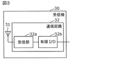
- FIG. 3 is a block diagram showing a configuration of the receiver in FIG.
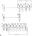
- FIG. 4 is a flowchart showing the operation of the wireless sensor system according to the first embodiment.
- FIG. 5 is a diagram illustrating an example of a data structure of a packet generated by the wireless sensor terminal.
- FIG. 6 is a timing chart showing the operation of the wireless sensor terminal.
- FIG. 7 is a diagram illustrating another example of a data structure of a packet transmitted by the wireless sensor terminal.
- FIG. 8 is a block diagram illustrating a configuration of the wireless sensor system according to the second embodiment.
- FIG. 5 is a diagram illustrating an example of a data structure of a packet generated by the wireless sensor terminal.
- FIG. 6 is a timing chart showing the operation of the wireless sensor terminal.
- FIG. 7 is a diagram illustrating
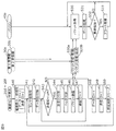
- FIG. 9 is a flowchart showing the operation of the wireless sensor system according to the second embodiment.
- FIG. 10 is a diagram illustrating an example of a data structure of a packet generated by the wireless sensor terminal.
- FIG. 11 is a timing chart showing the operation of the wireless sensor terminal.
- FIG. 12 is a block diagram illustrating a configuration of the wireless sensor system according to the third embodiment.
- FIG. 13 is a block diagram showing the configuration of the first gateway and the second gateway in FIG.
- FIG. 14 is a flowchart showing the operation of the wireless sensor system according to the third embodiment.
- FIG. 15 is a diagram illustrating an example of a data structure of a packet generated by the wireless sensor terminal.
- FIG. 1 is a block diagram showing a configuration of a wireless sensor system 10 according to the first embodiment.
- the wireless sensor system 10 is a system that collects sense values detected by a sensor attached to a moving body, and includes a plurality of wireless sensor terminals 20a to 20c attached to each moving body (not shown), a receiver 30, A personal computer (personal computer) 40 is provided.
- Each of the wireless sensor terminals 20a to 20c is a portable terminal that is attached to each moving body, includes a sensor, and wirelessly transmits data including a sense value detected by the sensor as a packet. It is attached to a person and transmits biological information such as the body temperature of the person. Each time a sense value is newly detected by the sensor, the wireless sensor terminals 20a to 20c wirelessly transmit the data including the detected sense value and a unique data ID corresponding to the detection as a packet (connectionless) Type transmission).
- the broadcast transmission here is a one-way transmission that does not require confirmation of reception of ACK or the like.
- the data ID is a sequential numerical value in the present embodiment, and specifically, an integer that is incremented by 1 each time a sense value is newly detected by the sensor.
- the receiver 30 is a communication interface that functions as a receiving base station that wirelessly receives packets transmitted from the wireless sensor terminals 20a to 20c and transfers them to the personal computer 40.
- the receiver 30 is connected to the personal computer 40 via a network and operates by receiving power supply from the personal computer 40.
- the personal computer 40 is an example of a host that receives packets from the receiver 30, and includes a CPU, a ROM, a RAM, a hard disk for storing programs and data, a personal computer main body including an input / output port connected to the receiver 30, a display, and a keyboard. And an input device such as a mouse.
- the personal computer 40 extracts the data ID and the sense value from the packet received from the receiver 30, and stores the extracted data ID and the sense value in association with each other.
- FIG. 2 is a block diagram showing the configuration of the wireless sensor terminals 20a to 20c in FIG.
- Each of the wireless sensor terminals 20a to 20c has the same configuration, and includes an antenna 21, a wireless communication / control circuit 22, a measurement circuit 23, and a battery 24.
- the antenna 21 is an antenna suitable for the frequency band used for the wireless sensor terminals 20a to 20c to transmit packets wirelessly.
- the wireless communication / control circuit 22 is a circuit that performs wireless communication and control in the wireless sensor terminals 20a to 20c, and includes a transmission unit 22a, a RAM 22b, a CPU 22c, and a ROM 22d.
- the transmission unit 22a is a transmission circuit that modulates and amplifies the packet output from the CPU 22c into a high-frequency signal in a predetermined frequency band, and supplies the modulated signal to the antenna 21.
- the transmission unit 22a transmits, for example, according to a Bluetooth (registered trademark) communication method.
- the RAM 22b is a memory that temporarily stores data.
- the ROM 22d is a read-only memory that holds programs and data.
- the CPU 22c executes a program held in the ROM 22d while using the RAM 22b, thereby performing control in the wireless sensor terminals 20a to 20c such as outputting the data obtained by the measurement circuit 23 as a packet to the transmission unit 22a.
- the measurement circuit 23 includes a sensor 23a and an ADC 23b, and generates a sense value by converting an analog signal detected by the sensor 23a into a digital signal by the ADC 23b, and outputs the sense value to the CPU 22c.
- the sensor 23a is, for example, a thermistor for measuring temperature.
- the battery 24 is a power source that supplies power to the wireless communication / control circuit 22 and the measurement circuit 23.
- the battery 24 may include not only a battery but also a constant voltage circuit that obtains power from the battery and converts it into a predetermined voltage. Good.
- FIG. 3 is a block diagram showing a configuration of the receiver 30 in FIG.
- the receiver 30 includes an antenna 31 and a communication circuit 32.
- the antenna 31 is an antenna suitable for a frequency band used for receiving packets transmitted wirelessly from the wireless sensor terminals 20a to 20c.
- the communication circuit 32 is a circuit that wirelessly receives a packet received via the antenna 31 and transfers the packet to the personal computer 40, and includes a receiving unit 32a and a wired I / O 32b.
- the receiving unit 32a is a circuit that extracts a data body (payload) by removing a header depending on a communication method after filtering and demodulating a high frequency signal received via the antenna 31 and restoring the packet.
- the receiving unit 32a receives, for example, according to a Bluetooth (registered trademark) communication method.
- the wired I / O 32b transfers the data body extracted by the receiving unit 32a (hereinafter, the data body from which the header depending on the communication method is removed is also referred to as “packet”) to the personal computer 40 connected via the wire. Communication interface.
- FIG. 4 is a flowchart showing the operation of the wireless sensor system 10 according to the first embodiment. Here, the operations of the wireless sensor terminals 20a to 20c, the receiver 30, and the personal computer 40 and the exchange of data with each other are shown.
- the wireless communication / control circuit 22 (more specifically, the CPU 22c) is activated and initialized when the battery 24 is attached (S10).
- the data ID is set to 1 as initialization. Note that the initial value of the data ID is not limited to 1, and may be any other value.
- the wireless communication / control circuit 22 acquires a sense value generated by converting the analog signal detected by the sensor 23a into a digital signal by the ADC 23b from the measurement circuit 23 (S11).
- the wireless communication / control circuit 22 adds the data ID generated immediately before (the data ID initialized in step S10 for the first time and the data ID incremented in step S15 for the second time or later) to the acquired sense value ( S12).
- FIG. 5 is a diagram illustrating an example of a data structure of a packet generated by the wireless sensor terminals 20a to 20c. A data structure is shown in which a data ID is added to the sense value and a header is added.
- the identification information (transmission source address or the like) of the wireless sensor terminals 20a to 20c may be included in the header, or in addition to or instead of the data body (payload).
- the wireless communication / control circuit 22 broadcasts the generated packet via the antenna 21 (transmission step S14).
- the wireless communication / control circuit 22 increments the data ID by 1 (S15) and enters a sleep state for a predetermined time (S16). In the sleep state, the wireless communication / control circuit 22 performs only minimum operations such as monitoring the passage of a predetermined time, and the power consumption of the wireless sensor terminals 20a to 20c is minute.
- the wireless communication / control circuit 22 again repeats the processing from the acquisition of the sense value (S11) to the sleep state (S16).
- FIG. 6 is a timing chart showing the operation of the wireless sensor terminals 20a to 20c.
- FIG. 6A shows the overall operation of the wireless sensor terminals 20a to 20c (timing for operating in a normal state other than the sleep state).
- FIG. 6B shows the operation of the measurement circuit 23 in the wireless sensor terminals 20a to 20c.
- FIG. 6C shows the wireless transmission operation of the wireless sensor terminals 20a to 20c.
- FIG. 6D shows details of wireless transmission of the wireless sensor terminals 20a to 20c (expanded timing of FIG. 6C).
- the wireless sensor terminals 20a to 20c are operated for a certain period of time ("operation time” in the figure) and then enter the sleep state after a certain period ("startup” in the figure). Repeat at intervals ").
- the predetermined time for entering the sleep state corresponds to a time obtained by subtracting “operation time” from “start-up time”. For example, the activation time is 1 hour and the operation time is 2 seconds.
- the data ID is incremented by one.
- the data ID is set so as to match the number of times of measurement (“measurement No.” in the figure).
- one operation time is a time during which the wireless sensor terminals 20a to 20c return to the normal state from the sleep state to obtain a sense value (the time of “start-up process” in the figure). ) And the time (“transmission interval”, “transmission time” in the figure) for transmitting the obtained sense value as a packet.
- the communication circuit 32 when the communication circuit 32 wirelessly receives the packet transmitted from the wireless sensor terminals 20a to 20c, the communication circuit 32 removes the header depending on the communication method. The data is transferred to the personal computer 40 (reception step S20).
- the personal computer 40 receives and manages the packets transferred from the receiver 30 (management steps S30 to S33).
- the personal computer 40 acquires the packet transferred from the receiver 30 (S30), it extracts the data ID and the sense value from the acquired packet, and associates the extracted data ID with the sense value. Data storage processing is performed (S31).
- the personal computer 40 determines whether or not there is a missing data ID (that is, reception omission) by checking the continuity between the data ID just received and the data ID just received, or It is determined whether or not an abnormality has been detected by determining whether or not the sense value just received is within the reference range (S32). As a result, if it is determined that an abnormality has been detected (YES in S32), the personal computer 40 issues an alert by displaying on the display, outputting an alarm, sending an e-mail to a predetermined destination, etc. (S33). .
- the above-described processing (S30 to S33) in the personal computer 40 is based on the wireless sensor terminal identification information included in the packet header or data body (payload) transmitted from the wireless sensor terminals 20a to 20c. This is performed for each of the sensor terminals 20a to 20c.
- the data ID used in the wireless sensor system 10 is a value that is updated each time a new measurement is performed, that is, a sense value is newly detected (an ID assigned in the application layer).
- an ID assigned in the application layer it is different from the packet ID (for example, a sequence number in TCP (Transmission Control Protocol)) that may be assigned as a standard in a communication layer lower than the application layer. Since the packet ID given as standard in the communication layer below the application layer is set to a different value when it is separated into different packets even if it is data constituting the same sense value, it is measured once. It cannot be used for management in units of (that is, one sense value).
- the wireless sensor system 10 is attached to a moving body, has a sensor 23a, and wirelessly transmits data including a sense value detected by the sensor 23a as a packet.
- 20a to 20c a receiver 30 that wirelessly receives packets transmitted from the wireless sensor terminals 20a to 20c, and a personal computer 40 that is a host that receives packets from the receiver 30.
- the wireless sensor terminals 20a to 20c broadcast and transmit data including the detected sense value and a unique data ID corresponding to the detection as a packet.
- the personal computer 40 extracts the data ID and the sense value from the packet received from the receiver 30, and stores the extracted data ID and the sense value in association with each other.
- the data collection method by the wireless sensor system 10 is a data collection method by the wireless sensor system 10 including the wireless sensor terminals 20a to 20c, the receiver 30, and the personal computer 40 as a host.
- the wireless sensor terminals 20a to 20c wirelessly transmit data including a sense value detected by the sensor 23a attached to the moving body as a packet, and the receiver 30 receives the wireless sensor terminals 20a to 20c from the wireless sensor terminals 20a to 20c.
- the receiving step S20 for receiving the transmitted packet wirelessly and the management steps S30 to S33 for the personal computer 40 to receive and manage the packet from the receiver 30 are included.
- the wireless sensor terminals 20a to 20c wirelessly use data including the detected sense value and a unique data ID corresponding to the detection as a packet.
- the personal computer 40 extracts the data ID and the sense value from the packet received from the receiver 30, and stores the extracted data ID and the sense value in association with each other.
- the personal computer 40 that has received the packet determines the data ID contained in the packet, thereby It is possible to know which detection (for example, what number of detections) the sensor 23a has, or that the reception has been missed. Therefore, it is suppressed that the power consumption of the wireless sensor terminals 20a to 20c is increased by repeatedly transmitting packets including the same sense value in vain.
- the processing is complicated by receiving the same data repeatedly, or the weight of the data is wrong due to the variation in the number of receptions depending on the situation of radio wave propagation. The data reception process is surely and easily performed and simplified.
- RSSI Receiveived Signal Strength Indicator; received signal strength
- BER Bit Error Rate
- SN ratio signal-noise ratio
- the packet transmitted by the wireless sensor terminals 20a to 20c includes the data ID and the latest sense value, but may include the past sense value. Good.
- FIG. 7 is a diagram showing another example of a data structure of a packet transmitted by the wireless sensor terminals 20a to 20c.
- the packet in addition to the data ID and the latest sense value (“latest sense value”), the past sense value (here, the “previous sense value” obtained in the previous measurement). ) Is stored. That is, in this example, every time a sense value is newly detected by the sensor 23a, the wireless sensor terminals 20a to 20c further detect a sense value previously detected by the sensor 23a (here, the previous sense value).
- the packet is transmitted after being included in the packet.
- the personal computer 40 that has received a packet that includes not only a new sense value but also a past sense value uses the past sense value included in the packet to check against the already received sense value. And the sense value that could not be received can be complemented, and data processing in the personal computer 40 can be performed reliably and easily.
- a past sense value (here, “previous sense value”) and its past are included in the packet.
- a data ID corresponding to the sense value (here, “previous data ID”) is stored.
- the wireless sensor terminals 20a to 20c add to the sense value previously detected by the sensor 23a (here, the previous sense value).
- the packet is transmitted after the data ID (here, the previous data ID) corresponding to the sense value detected in the past is included in the packet.
- the personal computer 40 since the data ID corresponding to the past sense value is included in the packet, the personal computer 40 that has received such a packet uses the past sense value included in the packet and its data ID in pairs. Therefore, the data ID of the sense value that has already been received can also be checked and confirmed, or the sense value and data ID that could not be received can be complemented, and the data processing in the personal computer 40 is more reliable and easy. become.
- FIG. 8 is a block diagram showing a configuration of the wireless sensor system 10a according to the second embodiment.
- the wireless sensor system 10a is a system that collects sense values detected by a sensor attached to a moving body, and includes a plurality of wireless sensor terminals 20d to 20f and a plurality of receivers attached to each moving body (not shown). (The 1st receiver 30a and the 2nd receiver 30b) and the personal computer 40a are provided.
- the wireless sensor terminals 20d to 20f have the basic configuration shown in FIG. 2 and have at least the same functions as the wireless sensor terminals 20d to 20f of the first embodiment, but in addition, the same It has a function of repeatedly transmitting packets. More specifically, each time a sense value is newly detected by the sensor 23a, the wireless sensor terminals 20d to 20f transmit a packet including the same data ID and sense value at a predetermined time interval (M times). repeat. At this time, when the wireless sensor terminals 20d to 20f repeat the transmission of the packet, each of the packets in the repetition includes a transmission ID corresponding to the number of transmissions out of a predetermined number (M times). Send the packet.
- the data ID is a value indicating the number of transmission repetitions.
- Both the first receiver 30a and the second receiver 30b are provided with the basic configuration shown in FIG. 3 as in the first embodiment, and have the same functions as the receiver 30 in the first embodiment. That is, each of the first receiver 30a and the second receiver 30b functions as a receiving base station that wirelessly receives packets transmitted from the wireless sensor terminals 20d to 20f and transfers them to the personal computer 40a. However, the first receiver 30a and the second receiver 30b are installed in different locations in advance so as not to miss packets transmitted wirelessly from the wireless sensor terminals 20d to 20f that are attached to the moving body and move. Installed.
- the personal computer 40a performs processing associated with repeatedly receiving the same packet. That is, in the present embodiment, the personal computer 40a counts the number of packets that include the same data ID (and have different transmission IDs) among the packets received from the first receiver 30a and the second receiver 30b. Then, a reception rate that is a ratio of the counted number to the predetermined number of times (M times) is calculated. The personal computer 40a stores only the data in one packet for a plurality of packets including the same data ID. For the predetermined number of times (M times), the personal computer 40a is shared with the wireless sensor terminals 20d to 20f.
- the personal computer 40a sometimes receives duplicate packets including the same data ID and the same transmission ID from the first receiver 30a and the second receiver 30b.
- the two packets may be stored after distinguishing them, or only one of them may be stored.
- FIG. 9 is a flowchart showing the operation of the wireless sensor system 10a according to the second embodiment.
- the operations of the wireless sensor terminals 20d to 20f, the receivers (the first receiver 30a and the second receiver 30b), the personal computer 40a, and the mutual exchange of data are shown.
- the wireless communication / control circuit 22 (more specifically, the CPU 22c) is activated and initialized when the battery 24 is attached (S40).
- the data ID is set to 1 and the transmission ID is set to 1.
- the initial values of the data ID and the transmission ID are not limited to 1, and may be other arbitrary values.
- the wireless communication / control circuit 22 acquires from the measurement circuit 23 a sense value generated by converting the analog signal detected by the sensor 23a into a digital signal by the ADC 23b (S41).
- the wireless communication / control circuit 22 adds the data ID generated immediately before (the data ID initialized in step S40 for the first time and the data ID incremented in step S48 for the second time or later) to the acquired sense value ( S42).
- the radio communication / control circuit 22 determines that the transmission ID generated immediately before (the transmission ID initialized in step S40 for the first time and the transmission ID incremented in step S47 for the first time) is a predetermined value M (the predetermined number of times described above). It is determined whether or not the value is equal to or smaller than (S43).
- the predetermined value M is a value set in advance as the number of repeated transmissions of packets including the same data ID, and is 720, for example.
- FIG. 10 is a diagram illustrating an example of a data structure of a packet generated by the wireless sensor terminals 20d to 20f. A data structure is shown in which a data ID and a transmission ID are added to the sense value, and a header is further added.
- the wireless communication / control circuit 22 broadcasts the generated packet via the antenna 21 (transmission step S46).
- the wireless communication / control circuit 22 increments the transmission ID by 1 (S47), and repeats the determination in step S43 and the subsequent processing again.
- step S43 If it is determined in step S43 that the transmission ID is not less than or equal to the predetermined value M (NO in step S43), the wireless communication / control circuit 22 increments the data ID by 1 (S48) and initializes the transmission ID ( Here, after being set to 1 (S49), the sleep state is entered for a predetermined time (S50).
- the wireless communication / control circuit 22 repeats the processing from the acquisition of the sense value (S41) to the sleep state (S50) again.
- FIG. 11 is a timing chart showing the operation of the wireless sensor terminals 20d to 20f.
- FIG. 11A shows the overall operation of the wireless sensor terminals 20d to 20f (timing for operating in a normal state other than the sleep state).
- FIG. 11B shows the operation of the measurement circuit 23 in the wireless sensor terminals 20d to 20f.
- FIG. 11C shows the wireless transmission operation of the wireless sensor terminals 20d to 20f.
- FIG. 11D shows the details of wireless transmission of the wireless sensor terminals 20d to 20f (expanded timing of FIG. 11C).
- the wireless sensor terminals 20d to 20f perform an operation in which the wireless sensor terminals 20d to 20f enter a sleep state after operating for a certain period of time (“operation time” in the figure). Repeatedly ("Startup interval" in the figure).
- the wireless sensor terminals 20d to 20f repeat the process of transmitting a packet including the same data ID m times and going to the sleep state M / m times, thereby repeating the packet including the same data ID M times in total.
- Such a total of M repeated transmissions are repeated at the illustrated measurement intervals.
- the activation interval is 5 minutes
- the operation time is 1 minute
- the measurement interval is 1 hour
- the M repeated transmissions are divided into a plurality of groups and dispersed in time, so that the possibility of normal reception even when the wireless sensor terminals 20d to 20f move is increased, and a plurality of sleeps are performed. Power consumption is suppressed depending on the state.
- the communication circuit 32 when the communication circuit 32 wirelessly receives the packet transmitted from the wireless sensor terminals 20d to 20f, the communication circuit 32 removes the header depending on the communication method. Then, the data is transferred to the personal computer 40a (reception steps S20a and S20b).
- the personal computer 40a receives and manages the packets transferred from the first receiver 30a and the second receiver 30b (management steps S30 to S33). That is, when the personal computer 40a acquires the packets transferred from the first receiver 30a and the second receiver 30b as in the first embodiment (S30), the data processing (as in the first embodiment) is performed. S31), abnormality detection determination (S32), and alerting (S33).
- the personal computer 40a performs the same data processing (S31) among the packets received from the first receiver 30a and the second receiver 30b.
- the number of packets including data IDs (and different transmission IDs) is counted, a reception rate that is a ratio of the counted number to the predetermined number of times (M times) is calculated, and a plurality of packets including the same data ID is included. Only the data in one packet is stored. Furthermore, if the personal computer 40a determines that the calculated reception rate is lower than the reference value (YES in step S32), it issues an alert (S33).
- the wireless sensor terminals 20d to 20f have the sense values newly detected by the sensor 23a.
- the personal computer 40a counts the number of packets including the same data ID among the packets received from the first receiver 30a and the second receiver 30b, and the reception is a ratio of the counted number to a predetermined number of times. Calculate the rate. For a plurality of packets including the same data ID, only the data in one packet is held.
- the wireless sensor terminals 20d to 20f repeat the transmission of the packet
- the wireless sensor terminals 20d to 20f transmit the packet after including the transmission ID corresponding to the transmission number of the predetermined number in each of the repeated packets.
- the personal computer 40a can determine that the reception has been missed not only for each data ID but also for each transmission ID in the same data ID by determining the transmission ID included in the received packet. Therefore, the time series change of the reception state is detected with higher accuracy.
- the wireless sensor terminals 20d to 20f are grouped into m ( ⁇ M) transmissions in order to repeatedly transmit packets including the same data ID M times. Such grouping is not always necessary. As long as the transmissions are distributed in time as much as possible, the M repeated transmissions may be transmitted at equal time intervals or non-uniform time intervals without being grouped.
- FIG. 12 is a block diagram illustrating a configuration of the wireless sensor system 10b according to the third embodiment.
- the wireless sensor system 10b is a system that collects sense values detected by a sensor attached to a moving body, and includes a plurality of wireless sensor terminals 20d to 20f and a plurality of gateways (attached to each moving body (not shown)).
- a plurality of gateways first gateway 50 a and second gateway 50 b
- a server 62 a server 62
- the Internet 60 which is a communication network connecting the mobile terminals 64, are also illustrated.
- Wireless sensor terminals 20d to 20f are the same as those in the second embodiment.
- the first gateway 50a and the second gateway 50b have a function of uploading various management information to the server 62 in addition to the functions of the first receiver 30a and the second receiver 30b and the personal computer 40a in the second embodiment. That is, the first gateway 50a and the second gateway 50b receive, as receivers, wirelessly packets transmitted from the wireless sensor terminals 20d to 20f, perform data processing and abnormality detection on the received packets as hosts, and The management information obtained by data processing and abnormality detection is uploaded to the server 62 via the Internet 60.
- the server 62 is a device that holds the management information uploaded from the first gateway 50a and the second gateway 50b and provides the management information to the mobile terminal 64 via the Internet 60.
- the CPU 62, the ROM, the RAM, the program, and the data A computer main body having a communication interface connected to the first gateway 50a and the second gateway 50b via the Internet 60, an input device such as a display, a keyboard and a mouse.
- the portable terminal 64 accesses the server 62 via the Internet 60, thereby browsing the management information held in the server 62 and notifying an abnormality (alert) detected by the first gateway 50a and the second gateway 50b. Is received via the server 62, for example, a smartphone or a tablet terminal.
- FIG. 13 is a block diagram showing the configuration of the first gateway 50a and the second gateway 50b in FIG.
- the first gateway 50 a and the second gateway 50 b both have the same configuration and include an antenna 51 and a communication / control circuit 52.
- the antenna 51 is an antenna suitable for a frequency band used for receiving packets transmitted wirelessly from the wireless sensor terminals 20d to 20f.
- the communication / control circuit 52 is a circuit that controls wireless communication with the wireless sensor terminals 20d to 20f, data processing and abnormality detection of packets acquired through wireless communication, and inter-network communication with the server 62 via the Internet 60. Yes, it comprises a receiving unit 52a, a RAM 52b, a CPU 52c, a ROM 52d, and a wired I / O 52e.
- the receiving unit 52a is a circuit that extracts a data body (payload) by removing a header depending on a communication method after filtering and demodulating a high-frequency signal received via the antenna 51 and restoring the packet, for example, , According to the communication method of Bluetooth (registered trademark).
- the RAM 52b is a memory that temporarily stores data.
- the ROM 52d is a read-only memory that holds programs and data.
- the CPU 52c executes a program stored in the ROM 52d while using the RAM 52b, thereby controlling the packet obtained by the receiving unit 52a to be transferred to the server 62 via the wired I / O 52e.
- the wired I / O 52 e is a communication interface that communicates with the server 62 via the Internet 60.
- FIG. 14 is a flowchart showing the operation of the wireless sensor system 10b according to the third embodiment.
- the operations of the wireless sensor terminals 20d to 20f, the plurality of gateways (the first gateway 50a and the second gateway 50b), the server 62, and the portable terminal 64, and the mutual exchange of data are shown.
- the operation of the wireless sensor terminals 20d to 20f is the same as that of the second embodiment (S40 to S50). That is, also in the present embodiment, the wireless sensor terminals 20d to 20f have the same data ID and sense value at a predetermined time interval (M times) every time a sense value is newly detected by the sensor 23a. Repeated transmission of packets containing. At this time, when the wireless sensor terminals 20d to 20f repeat the transmission of the packet, each of the packets in the repetition includes a transmission ID corresponding to the number of transmissions out of a predetermined number (M times). Send the packet. However, in the present embodiment, not only the latest sense value (the “latest sense value” in the figure) but also the past sense is included in the transmitted packet as in the packet data structure example shown in FIG. Value ("previous sense value" in the figure).
- first gateway 50a and the second gateway 50b perform the same processing as the first receiver 30a and the second receiver 30b and the personal computer 40a in the second embodiment (S30a to S33a, S30b to S33b).
- the first gateway 50a and the second gateway 50b perform data processing (S31a, S31b) in the data processing (transmission ID, data ID, latest sense value). And the previous sense value), the reception rate, the presence or absence of reception failure, and the like are uploaded to the server 62 via the Internet 60 as management information. Further, the first gateway 50a and the second gateway 50b issue an alert to the server 62 via the Internet 60 in alert notification (S33a, S33b).
- the server 62 receives data (management information) uploaded from the first gateway 50a and the second gateway 50b via the Internet 60 (S60), and after processing the data, accumulates it in the storage unit 62a it possesses. (S61).
- the server 62 when the server 62 receives an alert from the first gateway 50a and the second gateway 50b via the Internet 60, the server 62 transmits the alert to the portable terminal 64 via the Internet 60 (that is, issues an alert) (S62). ).
- the mobile terminal 64 accesses the server 62 via the Internet 60 according to the user's instruction, thereby browsing the management information held in the storage unit 62a of the server 62 (S70), the first gateway 50a, A notification (alert) of an abnormality detected by the second gateway 50b is received via the server 62 (S71).
- the first gateway 50a and the second gateway 50b have not only functions as receivers but also data processing by the CPU 52c. And also has an abnormality detection function. That is, the first gateway 50a and the second gateway 50b separate the data ID, transmission ID, sense value, and the like from the received packet, and extract only one sense value corresponding to the specific data ID. The reception status is determined from the ID, and the extracted sense value and data ID, the determined reception status, and the like are transmitted to the server 62. Thereby, even when the number of wireless sensor terminals becomes very large, the amount of data communicated between the first gateway 50a and the second gateway 50b and the server 62 is greatly reduced, and the communication load and the server 62 Processing load is reduced.
- the user can collect from the wireless sensor terminals 20d to 20f using the portable terminal 64 at hand from anywhere as long as the user can be connected to the Internet 60. It is convenient that the user can browse the sensed value, browse management information such as the reception rate and missed reception, and receive alerts.
- the wireless sensor system, the wireless sensor terminal, and the data collection method according to the present invention have been described based on the first to third embodiments, but the present invention is not limited to these embodiments. Unless it deviates from the main point of this invention, what made the various deformation
- the wireless sensor terminals 20a to 20f measure the temperature using the thermistor.
- the temperature sensor terminal 20a to 20f is not limited to such a measurement.
- a physical property value may be measured, a plurality of sensors may be provided to measure a plurality of physical property values, or different physical property values may be measured depending on the wireless sensor terminal. This makes it possible to collect and manage data according to various purposes.
- the wireless sensor terminals 20a to 20f are attached to a person as a moving body.
- the attached moving body is not limited to a person, and can be an animal, a car, or a movable equipment. It may be attached to other mobile bodies such as, or may be attached to different types of mobile bodies depending on the wireless sensor terminal.
- the wireless sensor terminals 20a to 20f transmit a packet including a data ID and a sense value.
- the information included in the packet is not limited to these, and includes time information, wireless information, and the like. Identification information of the sensor terminal, information indicating the remaining amount of the battery 24, and the like may be included.
- the host that has acquired such a packet can manage other information together with the sense value.
- the wireless sensor terminals 20a to 20f include the “previous sense value” obtained in the previous measurement as the past sense value included in the packet.
- the sense value is not limited to the previous sense value.
- the packet may also include sense values obtained by a plurality of previous measurements, an average value of a predetermined number of past sense values, a data ID corresponding to the plurality of sense values, and the like. As a result, the host that has acquired such a packet can make a more detailed determination about missed reception and restore a past sense value that missed reception.
- the data ID is a sequential value starting from 1.
- the data ID is not limited to this, and any ID may be used as long as it is unique each time a sense value is newly detected by the sensor. It may be a numerical value starting from a numerical value and increasing or decreasing by an arbitrary value.
- the present invention relates to a wireless sensor terminal that is attached to a moving body and wirelessly transmits data including a sense value detected by a sensor, a wireless sensor system including the wireless sensor terminal, and a data collection method using the wireless sensor system For example, it can be used as a system for collecting biological information of a person from a wireless sensor terminal attached to the person.
Landscapes
- Engineering & Computer Science (AREA)
- Computer Networks & Wireless Communication (AREA)
- Signal Processing (AREA)
- Multimedia (AREA)
- Mobile Radio Communication Systems (AREA)
- Detection And Prevention Of Errors In Transmission (AREA)
- Selective Calling Equipment (AREA)
- Arrangements For Transmission Of Measured Signals (AREA)
Abstract
無線センサシステム(10)は、移動体に取り付けられ、センサ(23a)で検知されたセンス値を含むデータをパケットとして無線で送信する無線センサ端末(20a~20c)と、送信されたパケットを無線で受け取る受信機(30)と、受信機(30)からパケットを受け取るパソコン(40)とを備える。無線センサ端末(20a~20c)は、センサ(23a)によってセンス値が新たに検知される度に、検知されたセンス値と当該検知に対応するユニークなデータIDと過去に検知されたセンス値とを含むデータをパケットとして無線でブロードキャスト送信することを、所定の時間間隔で所定の回数繰り返し、繰り返しにおいては、パケットのそれぞれに、所定の回数のうちの送信回数に対応する送信IDを含ませる。
Description
本発明は、移動体に取り付けられ、センサで検知されたセンス値を含むデータを無線で送信する無線センサ端末、その無線センサ端末を備える無線センサシステム、及び、その無線センサシステムによるデータ収集方法に関する。
移動体に取り付けられたセンサで得られたデータ(センス値)を無線で収集する無線センサシステムでは、移動体の位置によっては、遮蔽物や周辺反射物による電波伝搬の状況が悪化し、通信データの欠落が生じ得る。そのために、従来、無線センサシステムにおける通信データの欠落に対処する技術として様々なものが提案されている(例えば、特許文献1参照)。
特許文献1では、通信データの欠落が発生する程度に応じてデータ送信の頻度を設定することで、受信機で受信されるデータの頻度を均一化することで、センサから届くデータの個数が変動することによって重み付けや更新頻度が不安定になってしまうことを防止している。
しかしながら、特許文献1の技術では、コネクション型の通信を前提としているために、コネクションの確立に伴うオーバーヘッドが発生したり、受信確認に伴って無線センサ端末の動作時間(特に受信時間)が長くなってしまったり、再送制御に伴って無線センサ端末の動作時間が長くなってしまったりする。その結果、消費電力が大きくなり、移動体に取り付けられる無線センサ端末を電池で駆動しようとすると、無線センサ端末の動作寿命が著しく短くなってしまうという問題がある。
ここで、このようなコネクション型の通信に伴う問題を解消するために、受信応答を必要としないブロードキャスト型(コネクションレス型)の通信を採用することが考えられる。しかしながら、ブロードキャスト型の通信では、通信データの欠落に対処するために、同一のデータを繰り返し送信することが必要となる。このとき、データを送信する無線センサ端末では、受信機からのフィードバックを受け取れないために、適正な再送回数を決めることができず、再送回数に余裕を持たせざるを得なくなる。そのために、結局、データを送信する無線センサ端末の消費電力が大きくなったり、データを受信する受信側では、同一のデータを重複して受信することによって処理が煩雑化したり、電波伝搬の状況に依存して受信回数がばらつくことでデータの重み付けを誤ってしまうという問題が生じる。
そこで、本発明は、このような問題を解決するためになされたものであり、データを送信する無線センサ端末の消費電力が大きくなることを抑制しつつ、データの受信処理を確実かつ容易にできる無線センサシステム、無線センサ端末及びデータ収集方法を提供することを目的とする。
上記目的を達成するために、本発明の一形態に係る無線センサシステムは、移動体に取り付けられ、センサを有し、前記センサで検知されたセンス値を含むデータをパケットとして無線で送信する無線センサ端末と、前記無線センサ端末から送信された前記パケットを無線で受け取る受信機と、前記受信機から前記パケットを受け取るホストとを備え、前記無線センサ端末は、前記センサによって新たなセンス値が検知される度に、検知された前記センス値と当該検知に対応するユニークなデータIDとを含むデータを前記パケットとして無線でブロードキャスト送信する。
これにより、センス値を含むパケットはオーバーヘッドの少ないブロードキャスト型で送信されるので、コネクション型の通信に比べて、無線センサ端末の消費電力が大きくなることが抑制される。また、パケットには、センス値だけでなく、そのセンス値の検知に対応するユニークなデータIDが含まれるので、パケットを受信したホストは、パケットに含まれるデータIDを判別することで、パケットに含まれるセンス値がセンサによるどの検知(例えば、何回目の検知)によるデータなのか、あるいは、受信の取りこぼしがあったこと等を知ることができる。よって、同一のセンス値を含むパケットを無駄に繰り返し送信することによって無線センサ端末の消費電力が大きくなってしまうことが抑制される。そして、データを受信するホストでは、同一のデータを重複して受信することによって処理が煩雑化したり、電波伝搬の状況に依存して受信回数がばらつくことでデータの重み付けを誤ってしまったりすることが抑制され、データの受信処理が確実かつ容易になり、簡素化される。
また、受信の取りこぼしを評価することで、受信機の設置位置及び設置台数に依存した無線センサシステムの設置設定及び動作状態の評価が可能になり、受信機の設置位置及び設置台数の最適化が可能になる。
ここで、前記無線センサ端末は、前記センサによって新たなセンス値が検知される度に、所定の時間間隔で所定の回数、前記パケットの送信を繰り返し、前記ホストは、前記受信機から受け取った前記パケットのうち、同一のデータIDが含まれるパケットの個数を計数し、計数した前記個数の前記所定の回数に対する比率である受信率を算出し、同一のデータIDが含まれる複数の前記パケットについて、一つのパケットだけを保持する。
これにより、同じセンス値とデータIDとが含まれるパケットの送信が繰り返されるので、電波状況が悪化した場合であっても、受信の取りこぼしが抑制される。さらに、運用中にリアルタイムで受信率が算出されるので、受信機の設置位置及び設置台数の最適化が容易になる。また、ホストでは、同一のデータIDが含まれる複数のパケットのうちの一つだけが保持されるので、同一のパケットが複数回送信されることによるホストでの記憶容量の圧迫は回避される。
また、前記無線センサ端末は、前記パケットの送信を繰り返す際に、繰り返しにおける前記パケットのそれぞれに、前記所定の回数のうちの送信回数に対応する送信IDを含ませたうえで、前記パケットを送信する。
これにより、ホストは、受信したパケットに含まれる送信IDを判別することで、データIDごとだけでなく、同一のデータIDにおける送信IDごとに受信の取りこぼしがあったこと等を知ることができるので、受信状態の時系列変化がより高い精度で検知される。
また、前記無線センサ端末は、前記センサによって新たなセンス値が検知される度に、さらに、前記センサによって過去に検知されたセンス値を前記パケットに含ませたうえで、前記パケットを送信する。
これにより、新たなセンス値だけでなく過去のセンス値が含まれたパケットを受信したホストは、パケットに含まれる過去のセンス値を活用することで、既に受信しているセンス値と照合して確認したり、受信できなかったセンス値を補完したりすることができ、ホストでのデータ処理が確実かつ容易になる。
また、前記無線センサ端末は、前記センサによって新たなセンス値が検知される度に、さらに、過去に検知された前記センス値に対応するデータIDを前記パケットに含ませたうえで、前記パケットを送信してもよい。
これにより、パケットには、過去のセンス値に対応するデータIDが含まれるので、このようなパケットを受信したホストでは、パケットに含まれる過去のセンス値及びそのデータIDを対で活用することで、既に受信しているセンス値のデータIDについても照合して確認したり、受信できなかったセンス値及びデータIDを補完したりすることができ、ホストでのデータ処理がより確実かつ容易になる。
また、上記目的を達成するために、本発明の一形態に係る無線センサ端末は、上記無線センサシステムにおける無線センサ端末である。
これにより、センス値を含むパケットはオーバーヘッドの少ないブロードキャスト型で送信されるので、コネクション型の通信に比べて、無線センサ端末の消費電力が大きくなることが抑制される。また、パケットには、センス値だけでなく、そのセンス値の検知に対応するユニークなデータIDが含まれるので、パケットを受信したホストは、パケットに含まれるデータIDを判別することで、パケットに含まれるセンス値がセンサによるどの検知(例えば、何回目の検知)によるデータなのか、あるいは、受信の取りこぼしがあったこと等を知ることができる。よって、データを受信するホストでは、データの受信処理が確実かつ容易になり、簡素化される。
また、上記目的を達成するために、本発明の一形態に係るデータ収集方法は、移動体に取り付けられる無線センサ端末と受信機とホストとで構成される無線センサシステムによるデータ収集方法であって、前記無線センサ端末が、前記無線センサ端末が有するセンサで検知されたセンス値を含むデータをパケットとして無線で送信する送信ステップと、前記受信機が、前記無線センサ端末から送信された前記パケットを無線で受け取る受信ステップと、前記ホストが、前記受信機から前記パケットを受け取って管理する管理ステップとを含み、前記送信ステップでは、前記無線センサ端末は、前記センサによってセンス値が新たに検知される度に、検知された前記センス値と当該検知に対応するユニークなデータIDと過去に検知されたセンス値とを含むデータを前記パケットとして無線でブロードキャスト送信することを、所定の時間間隔で所定の回数繰り返し、前記繰り返しにおいては、前記パケットのそれぞれに、前記所定の回数のうちの送信回数に対応する送信IDを含ませ、前記管理ステップでは、前記ホストは、前記受信機から受け取った前記パケットのうち、同一のデータIDが含まれるパケットの個数を計数し、計数した前記個数の前記所定の回数に対する比率である受信率を算出し、同一のデータIDが含まれる複数の前記パケットについて、一つのパケット内のデータだけを保持する。
これにより、センス値を含むパケットはオーバーヘッドの少ないブロードキャスト型で送信されるので、コネクション型の通信に比べて、無線センサ端末の消費電力が大きくなることが抑制される。また、パケットには、センス値だけでなく、そのセンス値の検知に対応するユニークなデータIDが含まれるので、パケットを受信したホストは、パケットに含まれるデータIDを判別することで、パケットに含まれるセンス値がセンサによるどの検知(例えば、何回目の検知)によるデータなのか、あるいは、受信の取りこぼしがあったこと等を知ることができる。よって、データを受信するホストでは、データの受信処理が確実かつ容易になり、簡素化される。
本発明により、データを送信する無線センサ端末の消費電力が大きくなることを抑制しつつ、データの受信処理を確実かつ容易にできる無線センサシステム、無線センサ端末及びデータ収集方法が提供される。
以下、本発明の実施の形態について、図面を用いて詳細に説明する。なお、以下で説明する実施の形態は、いずれも本発明の一具体例を示すものである。以下の実施の形態で示される数値、材料、通信方式、データ構造、構成要素、構成要素の配置位置及び接続形態、ステップ、ステップの順序等は、一例であり、本発明を限定する主旨ではない。また、以下の実施の形態における構成要素のうち、本発明の最上位概念を示す独立請求項に記載されていない構成要素については、任意の構成要素として説明される。また、各図は、必ずしも厳密に図示したものではない。各図において、実質的に同一の構成については同一の符号を付し、重複する説明は省略又は簡略化する。
(実施の形態1)
まず、実施の形態1に係る無線センサシステムを説明する。
まず、実施の形態1に係る無線センサシステムを説明する。
図1は、実施の形態1に係る無線センサシステム10の構成を示すブロック図である。
無線センサシステム10は、移動体に取り付けられたセンサで検知されたセンス値を収集するシステムであり、移動体(図示せず)ごとに取り付けられる複数の無線センサ端末20a~20c、受信機30、及び、パソコン(パーソナルコンピュータ)40を備える。
無線センサ端末20a~20cは、移動体ごとに取り付けられ、センサを有し、センサで検知されたセンス値を含むデータをパケットとして無線で送信する携帯型の端末であり、例えば、特定のエリアにいる人に取り付けられ、人の体温等の生体情報を送信する。無線センサ端末20a~20cは、センサによってセンス値が新たに検知される度に、検知されたセンス値と当該検知に対応するユニークなデータIDとを含むデータをパケットとして無線でブロードキャスト送信(コネクションレス型送信)する。
なお、ここでのブロードキャスト送信は、ACK等の受信確認を必要としない一方向の送信である。また、データIDは、本実施の形態では、シーケンシャルな数値であり、具体的には、センサによってセンス値が新たに検知される度に1だけインクリメントされる整数である。
受信機30は、無線センサ端末20a~20cからブロードキャスト送信されたパケットを無線で受け取り、パソコン40に転送する受信基地局として機能する通信インタフェースである。受信機30は、例えば、パソコン40とネットワーク接続され、パソコン40からの電力供給を受けて動作する。
パソコン40は、受信機30からパケットを受け取るホストの一例であり、CPU、ROM、RAM、プログラムやデータを保存するハードディスク、受信機30と接続される入出力ポート等を備えるパソコン本体、ディスプレイ、キーボード及びマウス等の入力装置で構成される。パソコン40は、受信機30から受け取ったパケットからデータIDとセンス値とを取り出し、取り出したデータIDとセンス値とを対応づけて保持する。
図2は、図1における無線センサ端末20a~20cの構成を示すブロック図である。無線センサ端末20a~20cは、いずれも、同様の構成を備え、アンテナ21、無線通信・制御回路22、測定回路23、及び、電池24を備える。
アンテナ21は、無線センサ端末20a~20cが無線でパケットを送信するのに用いられる周波数帯域に適したアンテナである。
無線通信・制御回路22は、無線通信と無線センサ端末20a~20cにおける制御を行う回路であり、送信部22a、RAM22b、CPU22c及びROM22dで構成される。送信部22aは、CPU22cから出力されるパケットを所定の周波数帯域の高周波信号に変調して増幅し、アンテナ21に供給する送信回路であり、例えば、Bluetooth(登録商標)の通信方式に従って送信する。RAM22bは、一時的にデータを記憶するメモリである。ROM22dは、プログラム及びデータを保持する読み出し専用メモリである。CPU22cは、RAM22bを用いながらROM22dに保持されたプログラムを実行することで、測定回路23で得られたデータをパケットにして送信部22aに出力する等の無線センサ端末20a~20cにおける制御を行う。
測定回路23は、センサ23a及びADC23bで構成され、センサ23aで検知されたアナログ信号をADC23bでデジタル信号に変換することでセンス値を生成し、CPU22cに出力する回路である。センサ23aは、例えば、温度を測定するためのサーミスタである。
電池24は、無線通信・制御回路22及び測定回路23に電力を供給する電源であり、例えば、電池だけでなく、電池からの電力を得て所定電圧に変換する定電圧回路が含まれてもよい。
図3は、図1における受信機30の構成を示すブロック図である。受信機30は、アンテナ31、及び、通信回路32を備える。
アンテナ31は、無線センサ端末20a~20cから無線で送信されたパケットを受信するのに用いられる周波数帯域に適したアンテナである。
通信回路32は、アンテナ31を介して受信されたパケットを無線で受け取り、パソコン40に転送する回路であり、受信部32a及び有線I/O32bで構成される。受信部32aは、アンテナ31を介して受信された高周波信号をフィルタリングして復調し、パケットに復元した後に、通信方式に依存するヘッダを取り除くことでデータ本体(ペイロード)を取り出す回路である。受信部32aは、例えば、Bluetooth(登録商標)の通信方式に従って受信する。有線I/O32bは、受信部32aで取り出されたデータ本体(以下、通信方式に依存するヘッダが除去されたデータ本体も「パケット」と呼ぶ)を、有線を介して接続されたパソコン40に転送する通信インタフェースである。
次に、以上のように構成された本実施の形態における無線センサシステム10の動作(つまり、データ収集方法)について説明する。
図4は、実施の形態1に係る無線センサシステム10の動作を示すフローチャートである。ここでは、無線センサ端末20a~20c、受信機30及びパソコン40それぞれの動作と、相互のデータのやりとりが示されている。
無線センサ端末20a~20cでは、無線通信・制御回路22(より詳しくはCPU22c)は、電池24が装着されると起動し、初期化を行う(S10)。ここでは、初期化として、データIDを1に設定する。なお、データIDの初期値は1に限られず、他の任意の値であってもよい。
続いて、無線通信・制御回路22は、測定回路23から、センサ23aで検知されたアナログ信号がADC23bでデジタル信号に変換されて生成されたセンス値を取得する(S11)。
そして、無線通信・制御回路22は、取得したセンス値に、直前に生成したデータID(初回はステップS10で初期化したデータID、2回目以降はステップS15でインクリメントしたデータID)を付加する(S12)。
続いて、無線通信・制御回路22は、データIDを付加したセンス値に、通信方式(例えば、Bluetooth(登録商標))に従ったヘッダを付加することで、パケットを生成する(S13)。図5は、無線センサ端末20a~20cで生成されたパケットのデータ構造の一例を示す図である。センス値にデータIDが付加され、さらに、ヘッダが付加されたデータ構造が示されている。なお、無線センサ端末20a~20cの識別情報(送信元アドレス等)は、ヘッダに含まれてもよいし、それに加えて、あるいは、それに代えて、データ本体(ペイロード)に含まれてもよい。
そして、無線通信・制御回路22は、生成したパケットを、アンテナ21を介して、ブロードキャスト送信する(送信ステップS14)。
続いて、無線通信・制御回路22は、データIDを1だけインクリメントし(S15)、所定時間、スリープ状態となる(S16)。なお、スリープ状態では、無線通信・制御回路22は所定時間の経過を監視する等の最低限の動作だけを行い、無線センサ端末20a~20cの消費電力は微小となる。
所定時間が経過すると、無線通信・制御回路22は、再び、センス値の取得(S11)からスリープ状態になる(S16)までの処理を繰り返す。
図6は、無線センサ端末20a~20cの動作を示すタイミングチャートである。図6の(a)は無線センサ端末20a~20cの全体の動作(スリープ状態ではない通常状態で動作するタイミング)を示す。図6の(b)は無線センサ端末20a~20cにおける測定回路23の動作を示す。図6の(c)は無線センサ端末20a~20cの無線送信の動作を示す。図6の(d)は無線センサ端末20a~20cの無線送信の詳細(図6の(c)のタイミングを拡大したもの)を示す。
図6の(a)に示されるように、無線センサ端末20a~20cは、一定時間(図中の「動作時間」)だけ動作した後にスリープ状態になるという動作を一定周期(図中の「起動間隔」)で繰り返す。スリープ状態となる所定時間は、「起動時間」から「動作時間」を差し引いた時間に相当する。具体的な時間として、例えば、起動時間は1時間、動作時間は2秒である。
また、図6の(b)及び(c)に示されるように、測定回路23によって新たな測定が行われる度に、データIDが1ずつインクリメントされる。ここでは、測定回数(図中の「測定No.」)と一致するようにデータIDが設定されている。
また、図6の(d)に示されるように、1つの動作時間は、無線センサ端末20a~20cがスリープ状態から通常状態に戻ってセンス値を得る時間(図中の「起動処理」の時間)と、得たセンス値をパケットとして送信する時間(図中の「送信間隔」、「送信時間」)とからなる。
再び、図4を参照して、一方、受信機30では、通信回路32は、無線センサ端末20a~20cからブロードキャスト送信されたパケットを無線で受け取ると、通信方式に依存するヘッダを取り除いたうえで、パソコン40に転送する(受信ステップS20)。
パソコン40は、受信機30から転送されてきたパケットを受け取って管理する(管理ステップS30~S33)。
具体的には、パソコン40は、受信機30から転送されてきたパケットを取得すると(S30)、取得したパケットからデータIDとセンス値とを取り出し、取り出したデータIDとセンス値とを対応づけて保管するデータ処理を行う(S31)。
続いて、パソコン40は、直前に受信したデータIDといま受信したデータIDとの連続性を確認することによってデータIDの欠損(つまり、受信漏れ)がないか否かを判断したり、あるいは、いま受信したセンス値が基準範囲内か否かを判断したりすることで、異常を検知したか否かを判断する(S32)。その結果、異常を検知したと判断した場合には(S32でYES)、パソコン40は、ディスプレイへの表示、警報の出力、所定の宛先へのメール送信等によって、アラートを発報する(S33)。以上のパソコン40での処理(S30~S33)は、無線センサ端末20a~20cから送信されてきたパケットのヘッダ又はデータ本体(ペイロード)に含まれている無線センサ端末の識別情報に基づいて、無線センサ端末20a~20cのそれぞれごとに行われる。
なお、本実施の形態に係る無線センサシステム10で用いられたデータIDは、新たな測定の度、つまり、センス値が新たに検知される度に更新される値(アプリケーションレイヤーで付与されるID)であり、通信システムによってはアプリケーションレイヤーよりも下位の通信レイヤーにおいて標準で付与される場合があるパケットのID(例えば、TCP(Transmission Control Protocol)におけるシーケンス番号)とは異なる。アプリケーションレイヤーよりも下位の通信レイヤーにおいて標準で付与されるパケットのIDは、同一のセンス値を構成するデータであっても異なるパケットに分離されると異なる値が設定されるので、1回の測定(つまり、1個のセンス値)の単位での管理に用いることができない。
以上のように、本実施の形態に係る無線センサシステム10は、移動体に取り付けられ、センサ23aを有し、センサ23aで検知されたセンス値を含むデータをパケットとして無線で送信する無線センサ端末20a~20cと、無線センサ端末20a~20cから送信されたパケットを無線で受け取る受信機30と、受信機30からパケットを受け取るホストであるパソコン40とを備える。無線センサ端末20a~20cは、センサ23aによってセンス値が新たに検知される度に、検知されたセンス値と当該検知に対応するユニークなデータIDとを含むデータをパケットとして無線でブロードキャスト送信する。パソコン40は、受信機30から受け取ったパケットからデータIDとセンス値とを取り出し、取り出したデータIDとセンス値とを対応づけて保持する。
また、本実施の形態に係る無線センサシステム10によるデータ収集方法は、無線センサ端末20a~20cと受信機30とホストであるパソコン40とで構成される無線センサシステム10によるデータ収集方法であって、無線センサ端末20a~20cが、移動体に取り付けられたセンサ23aで検知されたセンス値を含むデータをパケットとして無線で送信する送信ステップS14と、受信機30が、無線センサ端末20a~20cから送信されたパケットを無線で受け取る受信ステップS20と、パソコン40が、受信機30からパケットを受け取って管理する管理ステップS30~S33とを含む。送信ステップS14では、無線センサ端末20a~20cは、センサ23aによってセンス値が新たに検知される度に、検知されたセンス値と当該検知に対応するユニークなデータIDとを含むデータをパケットとして無線でブロードキャスト送信し、管理ステップS30~S33では、パソコン40は、受信機30から受け取ったパケットからデータIDとセンス値とを取り出し、取り出したデータIDとセンス値とを対応づけて保持する。
これにより、センス値を含むパケットはオーバーヘッドの少ないブロードキャスト型で送信されるので、コネクション型の通信に比べて、無線センサ端末20a~20cの消費電力が大きくなることが抑制される。また、パケットには、センス値だけでなく、そのセンス値の検知に対応するユニークなデータIDが含まれるので、パケットを受信したパソコン40は、パケットに含まれるデータIDを判別することで、パケットに含まれるセンス値がセンサ23aによるどの検知(例えば、何回目の検知)によるデータなのか、あるいは、受信の取りこぼしがあったこと等を知ることができる。よって、同一のセンス値を含むパケットを無駄に繰り返し送信することによって無線センサ端末20a~20cの消費電力が大きくなってしまうことが抑制される。そして、データを受信するパソコン40では、同一のデータを重複して受信することによって処理が煩雑化したり、電波伝搬の状況に依存して受信回数がばらつくことでデータの重み付けを誤ってしまったりすることが抑制され、データの受信処理が確実かつ容易になり、簡素化される。
また、受信の取りこぼしを評価することで、受信機30の設置位置及び設置台数に依存した無線センサシステム10の設置設定及び動作状態の評価が可能になり、受信機30の設置位置及び設置台数の最適化が可能になる。
なお、パソコン40における受信状態の管理のために、受信機30で取得するRSSI(Received Signal Strength Indicator;受信信号強度)、BER(Bit Error Rate;ビット誤り率)、SN比(signal-noise ratio;信号雑音比)等の時系列変化を併用して保管してもよい。
また、本実施の形態に係る無線センサシステム10は、無線センサ端末20a~20cが送信するパケットには、データIDと最新のセンス値とが含まれたが、過去のセンス値が含まれてもよい。
図7は、無線センサ端末20a~20cが送信するパケットのデータ構造の他の一例を示す図である。図7の(a)では、パケットには、データID及び最新のセンス値(「最新センス値」)に加えて、過去のセンス値(ここでは、前回の測定で得られた「前回センス値」)が格納されている。つまり、この例では、無線センサ端末20a~20cは、センサ23aによってセンス値が新たに検知される度に、さらに、センサ23aによって過去に検知されたセンス値(ここでは、前回のセンス値)をパケットに含ませたうえで、パケットを送信する。これにより、新たなセンス値だけでなく過去のセンス値が含まれたパケットを受信したパソコン40では、パケットに含まれる過去のセンス値を活用することで、既に受信しているセンス値と照合して確認したり、受信できなかったセンス値を補完したりすることができ、パソコン40でのデータ処理が確実かつ容易になる。
また、図7の(b)では、パケットには、データID及び最新のセンス値(「最新センス値」)に加えて、過去のセンス値(ここでは、「前回センス値」)と、その過去のセンス値に対応するデータID(ここでは、「前回データID」)が格納されている。つまり、この例では、無線センサ端末20a~20cは、センサ23aによってセンス値が新たに検知される度に、センサ23aによって過去に検知されたセンス値(ここでは、前回のセンス値)に加えて、さらに、過去に検知されたセンス値に対応するデータID(ここでは、前回のデータID)をパケットに含ませたうえで、パケットを送信する。これにより、パケットには、過去のセンス値に対応するデータIDが含まれるので、このようなパケットを受信したパソコン40では、パケットに含まれる過去のセンス値及びそのデータIDを対で活用することで、既に受信しているセンス値のデータIDについても照合して確認したり、受信できなかったセンス値及びデータIDを補完したりすることができ、パソコン40でのデータ処理がより確実かつ容易になる。
(実施の形態2)
次に、実施の形態2に係る無線センサシステムを説明する。
次に、実施の形態2に係る無線センサシステムを説明する。
図8は、実施の形態2に係る無線センサシステム10aの構成を示すブロック図である。
無線センサシステム10aは、移動体に取り付けられたセンサで検知されたセンス値を収集するシステムであり、移動体(図示せず)ごとに取り付けられる複数の無線センサ端末20d~20f、複数の受信機(第1受信機30a及び第2受信機30b)、及び、パソコン40aを備える。
無線センサ端末20d~20fは、実施の形態1と同様に、図2に示される基本構成を備え、少なくとも実施の形態1の無線センサ端末20d~20fと同じ機能を有するが、それに加えて、同じパケットを繰り返し送信する機能を有する。より詳しくは、無線センサ端末20d~20fは、センサ23aによってセンス値が新たに検知される度に、所定の時間間隔で所定の回数(M回)、同じデータID及びセンス値を含むパケットの送信を繰り返す。このとき、無線センサ端末20d~20fは、パケットの送信を繰り返す際に、繰り返しにおけるパケットのそれぞれに、所定の回数(M回)のうちの送信回数に対応する送信IDを含ませたうえで、パケットを送信する。データIDは、本実施の形態では、送信の繰り返し回数を示す値である。
第1受信機30a及び第2受信機30bは、いずれも、実施の形態1と同様に、図3に示される基本構成を備え、実施の形態1の受信機30と同じ機能を有する。つまり、第1受信機30a及び第2受信機30bは、いずれも、無線センサ端末20d~20fからブロードキャスト送信されたパケットを無線で受け取り、パソコン40aに転送する受信基地局として機能する。ただし、第1受信機30a及び第2受信機30bは、移動体に取り付けられて移動する無線センサ端末20d~20fから無線で送信されるパケットをできるだけ取りこぼさないように、予め決められた異なる場所に設置される。
パソコン40aは、実施の形態1と同様の基本構成および機能に加えて、同一のパケットを繰り返し受信することに伴う処理をする。つまり、本実施の形態では、パソコン40aは、第1受信機30a及び第2受信機30bから受け取ったパケットのうち、同一のデータIDが含まれる(かつ、送信IDが異なる)パケットの個数を計数し、計数した個数の上記所定の回数(M回)に対する比率である受信率を算出する。パソコン40aは、同一のデータIDが含まれる複数のパケットについて、一つのパケット内のデータだけを記憶する。上記所定の回数(M回)については、パソコン40aは、無線センサ端末20d~20fと共有している。
なお、パソコン40aは、第1受信機30a及び第2受信機30bから、同一のデータID及び同一の送信IDが含まれるパケットを重複して受信することがあるが、この場合には、受信機を区別したうえで2つのパケットを保管してもよいし、一方のみを保管してもよい。
次に、以上のように構成された本実施の形態における無線センサシステム10aの動作(つまり、データ収集方法)について説明する。
図9は、実施の形態2に係る無線センサシステム10aの動作を示すフローチャートである。ここでは、無線センサ端末20d~20f、受信機(第1受信機30a及び第2受信機30b)及びパソコン40aそれぞれの動作と、相互のデータのやりとりが示されている。
無線センサ端末20d~20fでは、無線通信・制御回路22(より詳しくはCPU22c)は、電池24が装着されると起動し、初期化を行う(S40)。ここでは、初期化として、データIDを1に、送信IDを1に、設定する。なお、データID及び送信IDの初期値は1に限られず、他の任意の値であってもよい。
続いて、無線通信・制御回路22は、測定回路23から、センサ23aで検知されたアナログ信号がADC23bでデジタル信号に変換されて生成されたセンス値を取得する(S41)。
そして、無線通信・制御回路22は、取得したセンス値に、直前に生成したデータID(初回はステップS40で初期化したデータID、2回目以降はステップS48でインクリメントしたデータID)を付加する(S42)。
続いて、無線通信・制御回路22は、直前に生成した送信ID(初回はステップS40で初期化した送信ID、2回目以降はステップS47でインクリメントした送信ID)が所定値M(上記所定の回数を示す値)以下であるか否かを判断する(S43)。ここで、所定値Mは、同一のデータIDを含むパケットの繰り返し送信回数として予め設定された値であり、例えば、720である。
その結果、送信IDが所定値M以下である場合には(ステップS43でYES)、無線通信・制御回路22は、データIDを付加したセンス値に、送信IDを付加し(S44)、さらに、通信方式(例えば、Bluetooth(登録商標))に従ったヘッダを付加することで(S45)、パケットを生成する。図10は、無線センサ端末20d~20fで生成されたパケットのデータ構造の一例を示す図である。センス値にデータID及び送信IDが付加され、さらに、ヘッダが付加されたデータ構造が示されている。
そして、無線通信・制御回路22は、生成したパケットを、アンテナ21を介して、ブロードキャスト送信する(送信ステップS46)。
続いて、無線通信・制御回路22は、送信IDを1だけインクリメントし(S47)、再び、ステップS43の判断及びそれ以降の処理を繰り返す。
ステップS43において、送信IDが所定値M以下でないと判断した場合には(ステップS43でNO)、無線通信・制御回路22は、データIDを1だけインクリメントし(S48)、送信IDを初期化(ここでは、1に設定)した後に(S49)、所定時間、スリープ状態となる(S50)。
所定時間が経過すると、無線通信・制御回路22は、再び、センス値の取得(S41)からスリープ状態になる(S50)までの処理を繰り返す。
図11は、無線センサ端末20d~20fの動作を示すタイミングチャートである。図11の(a)は無線センサ端末20d~20fの全体の動作(スリープ状態ではない通常状態で動作するタイミング)を示す。図11の(b)は無線センサ端末20d~20fにおける測定回路23の動作を示す。図11の(c)は無線センサ端末20d~20fの無線送信の動作を示す。図11の(d)は無線センサ端末20d~20fの無線送信の詳細(図11の(c)のタイミングを拡大したもの)を示す。
図11の(a)に示されるように、本実施の形態では、無線センサ端末20d~20fは、一定時間(図中の「動作時間」)だけ動作した後にスリープ状態になるという動作を一定周期(図中の「起動間隔」)で繰り返す。
本実施の形態では、図11の(b)~(d)に示されるように、同一のデータIDを含むパケットをM回繰り返し送信するために、m(<M)回の送信にグループ化している。つまり、無線センサ端末20d~20fは、同一のデータIDを含むパケットをm回送信してスリープ状態になるという処理をM/m回繰り返すことで、同一のデータIDを含むパケットを合計M回繰り返し送信する。このような合計M回の繰り返し送信が、図示された測定間隔で繰り返される。具体的な時間として、例えば、起動間隔は5分、動作時間は1分、測定間隔は1時間、送信間隔は1秒である。よって、mは60(=動作時間1分/送信間隔1秒)であり、Mは720(=60×測定間隔1時間/起動間隔5分)である。
このように、M回の繰り返し送信を複数のグループに分割して時間的に分散させることで、無線センサ端末20d~20fが移動しても正常に受信できる可能性を高めつつ、複数回のスリープ状態によって消費電力を抑制している。
一方、図9の第1受信機30a及び第2受信機30bでは、通信回路32は、無線センサ端末20d~20fからブロードキャスト送信されたパケットを無線で受け取ると、通信方式に依存するヘッダを取り除いたうえで、パソコン40aに転送する(受信ステップS20a、S20b)。
パソコン40aは、実施の形態1と同様に、第1受信機30a及び第2受信機30bから転送されてきたパケットを受け取って管理する(管理ステップS30~S33)。つまり、パソコン40aは、実施の形態1と同様に、第1受信機30a及び第2受信機30bから転送されてきたパケットを取得すると(S30)、実施の形態1と同様にして、データ処理(S31)、異常検知の判断(S32)、及び、アラートの発報(S33)を行う。
ただし、本実施の形態では、実施の形態1での処理に加えて、パソコン40aは、データ処理(S31)として、第1受信機30a及び第2受信機30bから受け取ったパケットのうち、同一のデータIDが含まれる(かつ、送信IDが異なる)パケットの個数を計数し、計数した個数の上記所定の回数(M回)に対する比率である受信率を算出し、同一のデータIDが含まれる複数のパケットについて、一つのパケット内のデータだけを記憶する。さらに、パソコン40aは、算出した受信率が基準値よりも低いと判断した場合には(ステップS32でYES)、アラートを発報する(S33)。
以上のように、本実施の形態に係る無線センサシステム10aでは、実施の形態1における無線センサシステム10の機能に加えて、無線センサ端末20d~20fは、センサ23aによってセンス値が新たに検知される度に、所定の時間間隔で所定の回数、パケットの送信を繰り返す。そして、パソコン40aは、第1受信機30a及び第2受信機30bから受け取ったパケットのうち、同一のデータIDが含まれるパケットの個数を計数し、計数した個数の所定の回数に対する比率である受信率を算出する。同一のデータIDが含まれる複数のパケットについて、一つのパケット内のデータだけを保持する。
これにより、同じセンス値とデータIDとが含まれるパケットの送信が繰り返されるので、電波状況が悪化した場合であっても、受信の取りこぼしが抑制される。さらに、運用中にリアルタイムで受信率が算出されるので、第1受信機30a及び第2受信機30bの設置位置及び設置台数の最適化が容易になる。また、パソコン40aでは、同一のデータIDが含まれる複数のパケットのうちの一つのパケット内のデータだけが保持されるので、同一のデータIDが含まれるデータが重複して記録されることによる、パソコン40aでの記憶容量の圧迫は回避される。
また、無線センサ端末20d~20fは、パケットの送信を繰り返す際に、繰り返しにおけるパケットのそれぞれに、所定の回数のうちの送信回数に対応する送信IDを含ませたうえで、パケットを送信する。
これにより、パソコン40aは、受信したパケットに含まれる送信IDを判別することで、データIDごとだけでなく、同一のデータIDにおける送信IDごとに受信の取りこぼしがあったこと等を知ることができるので、受信状態の時系列変化がより高い精度で検知される。
なお、本実施の形態では、無線センサ端末20d~20fは、同一のデータIDを含むパケットをM回繰り返し送信するために、m(<M)回の送信にグループ化して送信したが、このようなグループ化は必ずしも必要ではない。できるだけ時間的に分散させて送信する限り、M回の繰り返し送信は、グループ化されないで、等時間間隔で、あるいは、不均一な時間間隔で送信されてもよい。
(実施の形態3)
次に、実施の形態3に係る無線センサシステムを説明する。
次に、実施の形態3に係る無線センサシステムを説明する。
図12は、実施の形態3に係る無線センサシステム10bの構成を示すブロック図である。
無線センサシステム10bは、移動体に取り付けられたセンサで検知されたセンス値を収集するシステムであり、移動体(図示せず)ごとに取り付けられる複数の無線センサ端末20d~20f、複数のゲートウェイ(第1ゲートウェイ50a及び第2ゲートウェイ50b)、サーバ62、及び、携帯端末64を備える。本図には、複数のゲートウェイ(第1ゲートウェイ50a及び第2ゲートウェイ50b)、サーバ62、及び、携帯端末64を接続する通信網であるインターネット60も併せて図示されている。
無線センサ端末20d~20fは、実施の形態2におけるものと同一である。
第1ゲートウェイ50a及び第2ゲートウェイ50bは、実施の形態2における第1受信機30a及び第2受信機30b並びにパソコン40aの機能に加えて、各種管理情報をサーバ62にアップロードする機能を有する。つまり、第1ゲートウェイ50a及び第2ゲートウェイ50bは、受信機として、無線センサ端末20d~20fからブロードキャスト送信されたパケットを無線で受け取り、ホストとして、受け取ったパケットに対するデータ処理及び異常検知を行い、さらに、データ処理及び異常検知で得た管理情報を、インターネット60を介してサーバ62にアップロードする。
サーバ62は、第1ゲートウェイ50a及び第2ゲートウェイ50bからアップロードされた管理情報を保持し、インターネット60を介して携帯端末64に管理情報を提供する装置であり、CPU、ROM、RAM、プログラムやデータを保存するハードディスク、インターネット60を介して第1ゲートウェイ50a及び第2ゲートウェイ50bと接続される通信インタフェース等を備えるコンピュータ本体、ディスプレイ、キーボード及びマウス等の入力装置で構成される。
携帯端末64は、インターネット60を介してサーバ62にアクセスすることで、サーバ62に保持された管理情報を閲覧したり、第1ゲートウェイ50a及び第2ゲートウェイ50bで検知された異常の通知(アラート)を、サーバ62を介して受信したりする端末であり、例えば、スマートフォンやタブレット端末等である。
図13は、図12における第1ゲートウェイ50a及び第2ゲートウェイ50bの構成を示すブロック図である。第1ゲートウェイ50a及び第2ゲートウェイ50bは、いずれも、同様の構成を備え、アンテナ51及び通信・制御回路52を備える。
アンテナ51は、無線センサ端末20d~20fから無線で送信されたパケットを受信するのに用いられる周波数帯域に適したアンテナである。
通信・制御回路52は、無線センサ端末20d~20fとの無線通信、無線通信で取得したパケットのデータ処理や異常検知、及び、インターネット60を介したサーバ62とのネットワーク間通信を制御する回路であり、受信部52a、RAM52b、CPU52c、ROM52d及び有線I/O52eで構成される。
受信部52aは、アンテナ51を介して受信された高周波信号をフィルタリングして復調し、パケットに復元した後に、通信方式に依存するヘッダを取り除くことでデータ本体(ペイロード)を取り出す回路であり、例えば、Bluetooth(登録商標)の通信方式に従って受信する。RAM52bは、一時的にデータを記憶するメモリである。ROM52dは、プログラム及びデータを保持する読み出し専用メモリである。CPU52cは、RAM52bを用いながらROM52dに保持されたプログラムを実行することで、受信部52aで得られたパケットを有線I/O52eを介してサーバ62に転送する制御を行う。有線I/O52eは、インターネット60を介してサーバ62と通信する通信インタフェースである。
次に、以上のように構成された本実施の形態における無線センサシステム10bの動作(つまり、データ収集方法)について説明する。
図14は、実施の形態3に係る無線センサシステム10bの動作を示すフローチャートである。ここでは、無線センサ端末20d~20f、複数のゲートウェイ(第1ゲートウェイ50a及び第2ゲートウェイ50b)、サーバ62、及び、携帯端末64それぞれの動作と、相互のデータのやりとりが示されている。
無線センサ端末20d~20fの動作は、実施の形態2と同じである(S40~S50)。つまり、本実施の形態においても、無線センサ端末20d~20fは、センサ23aによってセンス値が新たに検知される度に、所定の時間間隔で所定の回数(M回)、同じデータID及びセンス値を含むパケットの送信を繰り返す。このとき、無線センサ端末20d~20fは、パケットの送信を繰り返す際に、繰り返しにおけるパケットのそれぞれに、所定の回数(M回)のうちの送信回数に対応する送信IDを含ませたうえで、パケットを送信する。ただし、本実施の形態では、図15に示されるパケットのデータ構造例のように、送信されるパケットには、最新のセンス値(図中の「最新センス値」)だけでなく、過去のセンス値(図中の「前回センス値」)が含まれる。
一方、第1ゲートウェイ50a及び第2ゲートウェイ50bは、実施の形態2における第1受信機30a及び第2受信機30b並びにパソコン40aと同様の処理を行う(S30a~S33a、S30b~S33b)。
ただし、実施の形態2での処理に加えて、第1ゲートウェイ50a及び第2ゲートウェイ50bは、データ処理において(S31a、S31b)、取得したパケットに含まれるデータ(送信ID、データID、最新センス値及び前回センス値)や受信率、受信の取りこぼしの有無等を、管理情報として、インターネット60を介してサーバ62にアップロードする。さらに、第1ゲートウェイ50a及び第2ゲートウェイ50bは、アラート発報において(S33a、S33b)、インターネット60を介してサーバ62にアラートを発報する。
一方、サーバ62は、第1ゲートウェイ50a及び第2ゲートウェイ50bからインターネット60を介してアップロードされてきたデータ(管理情報)を受信し(S60)、データ処理をした後に、所持する記憶部62aに蓄積する(S61)。
また、サーバ62は、第1ゲートウェイ50a及び第2ゲートウェイ50bからインターネット60を介してアラートを受信した場合には、インターネット60を介して携帯端末64にアラートを伝達(つまり、発報)する(S62)。
一方、携帯端末64は、ユーザの指示に従って、インターネット60を介してサーバ62にアクセスすることで、サーバ62の記憶部62aに保持された管理情報を閲覧したり(S70)、第1ゲートウェイ50a及び第2ゲートウェイ50bで検知された異常の通知(アラート)を、サーバ62を介して受信したりする(S71)。
以上のように、本実施の形態に係る無線センサシステム10bでは、実施の形態1及び2と異なり、第1ゲートウェイ50a及び第2ゲートウェイ50bは、受信機としての機能だけでなく、CPU52cによるデータ処理及び異常検知の機能も有する。つまり、第1ゲートウェイ50a及び第2ゲートウェイ50bは、受信したパケットから、データID、送信ID、センス値等を分離するとともに特定のデータIDに対応するセンス値をひとつだけ抽出し、送信IDとデータIDとから受信状況を判定し、抽出したセンス値とデータID及び判定した受信状況等をサーバ62に送信する。これにより、無線センサ端末の台数が非常に多くなる場合でも第1ゲートウェイ50a及び第2ゲートウェイ50bとサーバ62との間で通信されるデータの量が大幅に削減され、通信負荷とサーバ62での処理負荷とが軽減される。
また、本実施の形態に係る無線センサシステム10bによれば、ユーザは、インターネット60に接続できる環境にいる限り、何処からでも、手元の携帯端末64を用いて、無線センサ端末20d~20fから収集されたセンス値を閲覧したり、受信率や受信の取りこぼし等の管理情報を閲覧したり、アラートを受信したりすることができ、便利である。
以上、本発明に係る無線センサシステム、無線センサ端末及びデータ収集方法について、実施の形態1~3に基づいて説明したが、本発明は、これらの実施の形態に限定されるものではない。本発明の主旨を逸脱しない限り、当業者が思いつく各種変形を実施の形態に施したものや、実施の形態における一部の構成要素を組み合わせて構築される別の形態も、本発明の範囲内に含まれる。
例えば、上記実施の形態1~3では、無線センサ端末20a~20fは、サーミスタを用いて温度を測定したが、このような測定に限定されず、湿度、血圧、気圧、心拍数等の他の物性値を測定してもよいし、複数のセンサを備えて複数の物性値を測定してもよいし、無線センサ端末によって異なる物性値を測定してもよい。これによって、多様な目的に沿ったデータ収集及び管理が可能になる。
また、上記実施の形態1~3では、無線センサ端末20a~20fは、移動体として、人に取り付けられたが、取り付けられる移動体としては人に限定されず、動物、車、移動可能な設備等の他の移動体に取り付けられてもよいし、無線センサ端末によって異なる種類の移動体に取り付けられてもよい。
また、上記実施の形態1~3では、無線センサ端末20a~20fは、データID及びセンス値等を含むパケットを送信したが、パケットに含ませる情報としては、これらに限られず、時刻情報、無線センサ端末の識別情報、電池24の残量を示す情報等を含ませてもよい。これによって、このようなパケットを取得したホストは、センス値とともに他の情報を管理できる。
また、上記実施の形態1及び3では、無線センサ端末20a~20fは、パケットに含ませる過去のセンス値として、前回の測定で得られた「前回センス値」をパケットに含ませたが、過去のセンス値としては、前回のセンス値に限られない。直前の複数回の測定で得られたセンス値や、過去の所定個数のセンス値の平均値や、それら複数のセンス値に対応するデータID等もパケットに含ませてもよい。これによって、このようなパケットを取得したホストは、より詳細に受信の取りこぼしについての判定や、受信を取りこぼした過去のセンス値の復元が可能になる。
また、上記実施の形態1~3では、データIDは、1から始まるシーケンシャルな値であったが、これに限られず、センサによってセンス値が新たに検知される度にユニークであれば、任意の数値から始まって任意の値だけ増加又は減少する数値であってもよい。
本発明は、移動体に取り付けられ、センサで検知されたセンス値を含むデータを無線で送信する無線センサ端末、その無線センサ端末を備える無線センサシステム、及び、その無線センサシステムによるデータ収集方法として、例えば、人に取り付けられた無線センサ端末から人の生体情報を収集するシステムとして、利用できる。
10、10a、10b 無線センサシステム
20a~20f 無線センサ端末
21 アンテナ
22 無線通信・制御回路
22a 送信部
22b RAM
22c CPU
22d ROM
23 測定回路
23a センサ
23b ADC
24 電池
30 受信機
30a 第1受信機
30b 第2受信機
31 アンテナ
32 通信回路
32a 受信部
32b 有線I/O
40、40a パソコン(パーソナルコンピュータ)
50a 第1ゲートウェイ
50b 第2ゲートウェイ
51 アンテナ
52 通信・制御回路
52a 受信部
52b RAM
52c CPU
52d ROM
52e 有線I/O
60 インターネット
62 サーバ
64 携帯端末
20a~20f 無線センサ端末
21 アンテナ
22 無線通信・制御回路
22a 送信部
22b RAM
22c CPU
22d ROM
23 測定回路
23a センサ
23b ADC
24 電池
30 受信機
30a 第1受信機
30b 第2受信機
31 アンテナ
32 通信回路
32a 受信部
32b 有線I/O
40、40a パソコン(パーソナルコンピュータ)
50a 第1ゲートウェイ
50b 第2ゲートウェイ
51 アンテナ
52 通信・制御回路
52a 受信部
52b RAM
52c CPU
52d ROM
52e 有線I/O
60 インターネット
62 サーバ
64 携帯端末
Claims (4)
- 移動体に取り付けられ、センサを有し、前記センサで検知されたセンス値を含むデータをパケットとして無線で送信する無線センサ端末と、
前記無線センサ端末から送信された前記パケットを無線で受け取る受信機と、
前記受信機から前記パケットを受け取るホストとを備え、
前記無線センサ端末は、前記センサによってセンス値が新たに検知される度に、検知された前記センス値と当該検知に対応するユニークなデータIDと過去に検知されたセンス値とを含むデータを前記パケットとして無線でブロードキャスト送信することを、所定の時間間隔で所定の回数繰り返し、前記繰り返しにおいては、前記パケットのそれぞれに、前記所定の回数のうちの送信回数に対応する送信IDを含ませ、
前記ホストは、前記受信機から受け取った前記パケットのうち、同一のデータIDが含まれるパケットの個数を計数し、計数した前記個数の前記所定の回数に対する比率である受信率を算出し、同一のデータIDが含まれる複数の前記パケットについて、一つのパケット内のデータだけを保持する
無線センサシステム。 - 前記無線センサ端末は、前記センサによってセンス値が新たに検知される度に、さらに、過去に検知された前記センス値に対応するデータIDを前記パケットに含ませたうえで、前記パケットを送信する
請求項1記載の無線センサシステム。 - 請求項1又は2記載の無線センサシステムにおける無線センサ端末。
- 移動体に取り付けられる無線センサ端末と受信機とホストとで構成される無線センサシステムによるデータ収集方法であって、
前記無線センサ端末が、前記無線センサ端末が有するセンサで検知されたセンス値を含むデータをパケットとして無線で送信する送信ステップと、
前記受信機が、前記無線センサ端末から送信された前記パケットを無線で受け取る受信ステップと、
前記ホストが、前記受信機から前記パケットを受け取って管理する管理ステップとを含み、
前記送信ステップでは、前記無線センサ端末は、前記センサによってセンス値が新たに検知される度に、検知された前記センス値と当該検知に対応するユニークなデータIDと過去に検知されたセンス値とを含むデータを前記パケットとして無線でブロードキャスト送信することを、所定の時間間隔で所定の回数繰り返し、前記繰り返しにおいては、前記パケットのそれぞれに、前記所定の回数のうちの送信回数に対応する送信IDを含ませ、
前記管理ステップでは、前記ホストは、前記受信機から受け取った前記パケットのうち、同一のデータIDが含まれるパケットの個数を計数し、計数した前記個数の前記所定の回数に対する比率である受信率を算出し、同一のデータIDが含まれる複数の前記パケットについて、一つのパケット内のデータだけを保持する
データ収集方法。
Priority Applications (1)
| Application Number | Priority Date | Filing Date | Title |
|---|---|---|---|
| JP2018554947A JP6551616B2 (ja) | 2016-12-05 | 2017-11-29 | 無線センサシステム、無線センサ端末及びデータ収集方法 |
Applications Claiming Priority (2)
| Application Number | Priority Date | Filing Date | Title |
|---|---|---|---|
| JP2016236029 | 2016-12-05 | ||
| JP2016-236029 | 2016-12-05 |
Publications (1)
| Publication Number | Publication Date |
|---|---|
| WO2018105458A1 true WO2018105458A1 (ja) | 2018-06-14 |
Family
ID=62491084
Family Applications (1)
| Application Number | Title | Priority Date | Filing Date |
|---|---|---|---|
| PCT/JP2017/042759 Ceased WO2018105458A1 (ja) | 2016-12-05 | 2017-11-29 | 無線センサシステム、無線センサ端末及びデータ収集方法 |
Country Status (2)
| Country | Link |
|---|---|
| JP (1) | JP6551616B2 (ja) |
| WO (1) | WO2018105458A1 (ja) |
Cited By (4)
| Publication number | Priority date | Publication date | Assignee | Title |
|---|---|---|---|---|
| JP2020005137A (ja) * | 2018-06-28 | 2020-01-09 | ラピスセミコンダクタ株式会社 | 通信システム、通信端末及び中継装置 |
| JP2020188456A (ja) * | 2019-03-29 | 2020-11-19 | 華廣生技股▲ふん▼有限公司Bionime Corporation | センサー装置と電子装置との間でデータを送信する方法及びシステム |
| JP2022050874A (ja) * | 2020-09-18 | 2022-03-31 | 日本ユニシス株式会社 | 環境情報提供システム、センサ装置、ゲートウェイ装置、センサ装置の制御方法、及びセンサ装置のプログラム |
| WO2024162482A1 (ja) * | 2023-01-31 | 2024-08-08 | 株式会社Kmc | 無線制御システム、無線機及び無線制御盤 |
Citations (4)
| Publication number | Priority date | Publication date | Assignee | Title |
|---|---|---|---|---|
| WO2012105062A1 (ja) * | 2011-02-01 | 2012-08-09 | オムロン株式会社 | 情報処理装置、センサシステム、設定方法、プログラムおよび記録媒体 |
| WO2015111377A1 (ja) * | 2014-01-21 | 2015-07-30 | 日本電気株式会社 | メータリング装置、及び遠隔検針のための方法 |
| WO2016027722A1 (ja) * | 2014-08-21 | 2016-02-25 | アプリックスIpホールディングス株式会社 | センサシステム及びセンサシステムの制御方法 |
| JP2016181812A (ja) * | 2015-03-24 | 2016-10-13 | 学校法人 関西大学 | 情報収集装置、センサーノードおよびそれらを備えた情報収集システム |
-
2017
- 2017-11-29 WO PCT/JP2017/042759 patent/WO2018105458A1/ja not_active Ceased
- 2017-11-29 JP JP2018554947A patent/JP6551616B2/ja active Active
Patent Citations (4)
| Publication number | Priority date | Publication date | Assignee | Title |
|---|---|---|---|---|
| WO2012105062A1 (ja) * | 2011-02-01 | 2012-08-09 | オムロン株式会社 | 情報処理装置、センサシステム、設定方法、プログラムおよび記録媒体 |
| WO2015111377A1 (ja) * | 2014-01-21 | 2015-07-30 | 日本電気株式会社 | メータリング装置、及び遠隔検針のための方法 |
| WO2016027722A1 (ja) * | 2014-08-21 | 2016-02-25 | アプリックスIpホールディングス株式会社 | センサシステム及びセンサシステムの制御方法 |
| JP2016181812A (ja) * | 2015-03-24 | 2016-10-13 | 学校法人 関西大学 | 情報収集装置、センサーノードおよびそれらを備えた情報収集システム |
Cited By (5)
| Publication number | Priority date | Publication date | Assignee | Title |
|---|---|---|---|---|
| JP2020005137A (ja) * | 2018-06-28 | 2020-01-09 | ラピスセミコンダクタ株式会社 | 通信システム、通信端末及び中継装置 |
| JP7262936B2 (ja) | 2018-06-28 | 2023-04-24 | ラピスセミコンダクタ株式会社 | 通信システム、通信端末及び中継装置 |
| JP2020188456A (ja) * | 2019-03-29 | 2020-11-19 | 華廣生技股▲ふん▼有限公司Bionime Corporation | センサー装置と電子装置との間でデータを送信する方法及びシステム |
| JP2022050874A (ja) * | 2020-09-18 | 2022-03-31 | 日本ユニシス株式会社 | 環境情報提供システム、センサ装置、ゲートウェイ装置、センサ装置の制御方法、及びセンサ装置のプログラム |
| WO2024162482A1 (ja) * | 2023-01-31 | 2024-08-08 | 株式会社Kmc | 無線制御システム、無線機及び無線制御盤 |
Also Published As
| Publication number | Publication date |
|---|---|
| JPWO2018105458A1 (ja) | 2019-10-24 |
| JP6551616B2 (ja) | 2019-07-31 |
Similar Documents
| Publication | Publication Date | Title |
|---|---|---|
| US11510170B2 (en) | Collaborating sensor array and method therefor | |
| JP6551616B2 (ja) | 無線センサシステム、無線センサ端末及びデータ収集方法 | |
| JP5953371B2 (ja) | 無線センサーネットワーク | |
| JP5469161B2 (ja) | 無線防災ノード及び無線防災システム | |
| EP2710891A1 (en) | Wireless notification system and method for electronic rodent traps | |
| US10548780B1 (en) | Apparatus for informing excretions and control method thereof | |
| JP3785137B2 (ja) | 計測情報送信装置及び多点計測情報収集システム | |
| US20120020237A1 (en) | Wireless communication system and parent node search method | |
| Sommer et al. | Low-power wide-area networks for industrial sensing applications | |
| JP2018528668A (ja) | ネットワークデバイスの状態の決定 | |
| JP5312205B2 (ja) | センサネットワークシステム | |
| US20100265098A1 (en) | Architecture, system and method for modular environmental conditions and object sensing | |
| JP2015014986A (ja) | 警報器及び警報システム | |
| US9843947B2 (en) | Visual signal strength indication for a wireless device | |
| CN112076025B (zh) | 一种纸尿裤报警装置与系统 | |
| KR102295589B1 (ko) | 화재 감지 시스템 | |
| JP2017188008A5 (ja) | ||
| GB2503467A (en) | Wireless sensor network | |
| EP3499928A1 (en) | Determining signal quality in a low-power wide-area network | |
| CN110823284A (zh) | 一种智能环境监测设备及监测方法 | |
| JP2008158794A (ja) | 監視システム | |
| JP2016192047A (ja) | 自動火災報知システムの子機、およびそれを用いた自動火災報知システム | |
| JP2016201605A (ja) | 無線通信端末、無線通信システム | |
| JP2020170946A (ja) | データ収集状況監視装置、データ収集状況監視プログラム、データ収集状況監視方法、及びデータ収集状況監視システム | |
| JP5760175B2 (ja) | 無線通信システム、中継装置及び中継装置のプログラム、無線端末及び無線端末のプログラム |
Legal Events
| Date | Code | Title | Description |
|---|---|---|---|
| 121 | Ep: the epo has been informed by wipo that ep was designated in this application |
Ref document number: 17879525 Country of ref document: EP Kind code of ref document: A1 |
|
| ENP | Entry into the national phase |
Ref document number: 2018554947 Country of ref document: JP Kind code of ref document: A |
|
| NENP | Non-entry into the national phase |
Ref country code: DE |
|
| 122 | Ep: pct application non-entry in european phase |
Ref document number: 17879525 Country of ref document: EP Kind code of ref document: A1 |