WO2018105288A1 - 制御装置 - Google Patents
制御装置 Download PDFInfo
- Publication number
- WO2018105288A1 WO2018105288A1 PCT/JP2017/040009 JP2017040009W WO2018105288A1 WO 2018105288 A1 WO2018105288 A1 WO 2018105288A1 JP 2017040009 W JP2017040009 W JP 2017040009W WO 2018105288 A1 WO2018105288 A1 WO 2018105288A1
- Authority
- WO
- WIPO (PCT)
- Prior art keywords
- ecu
- signal
- starter
- supplied
- diode
- Prior art date
- Legal status (The legal status is an assumption and is not a legal conclusion. Google has not performed a legal analysis and makes no representation as to the accuracy of the status listed.)
- Ceased
Links
Images



Classifications
-
- F—MECHANICAL ENGINEERING; LIGHTING; HEATING; WEAPONS; BLASTING
- F02—COMBUSTION ENGINES; HOT-GAS OR COMBUSTION-PRODUCT ENGINE PLANTS
- F02N—STARTING OF COMBUSTION ENGINES; STARTING AIDS FOR SUCH ENGINES, NOT OTHERWISE PROVIDED FOR
- F02N11/00—Starting of engines by means of electric motors
-
- F—MECHANICAL ENGINEERING; LIGHTING; HEATING; WEAPONS; BLASTING
- F02—COMBUSTION ENGINES; HOT-GAS OR COMBUSTION-PRODUCT ENGINE PLANTS
- F02N—STARTING OF COMBUSTION ENGINES; STARTING AIDS FOR SUCH ENGINES, NOT OTHERWISE PROVIDED FOR
- F02N11/00—Starting of engines by means of electric motors
- F02N11/08—Circuits specially adapted for starting of engines
Definitions
- the present invention relates to a control device.
- an internal combustion engine of an automobile is difficult to start alone, for example, it may be started using a starter.
- a starter for example, a starter provided with an electrically driven starter motor is generally known.
- the starter motor is connected to a power source via a starter relay configured as a so-called meshing relay.
- a drive signal is supplied to the starter relay, power is supplied from the power source to the starter, and the starter motor is driven to start the internal combustion engine.
- ECUs electronice control units
- the ECU for controlling the start of the internal combustion engine uses a control signal from another unit (for example, another ECU) that performs the main control.
- the starter may be driven by operating in a dependent manner.
- Patent Document 1 discloses an example of a configuration for starting an internal combustion engine by controlling the operation of a drive circuit for driving a starter relay by a control unit such as a microcomputer.
- the present invention has been made in view of the above problems, and an object of the present invention is to control the operation of a starter that starts an internal combustion engine by using a control signal supplied from another unit. It is an object of the present invention to provide a control device capable of realizing control in a more preferable manner.
- a drive circuit (110) from an input terminal (P11) to which a first signal is supplied from another unit, a drive circuit (110), and the input terminal (P11) A diode (D21) connected so that the first signal is supplied toward an input side of the drive circuit (110), and the drive circuit (110) receives the first input
- a control device is provided that drives the starter relay by supplying a second signal to the starter relay (210) based on the signal.
- a control device capable of realizing the control of the operation of the starter for starting the internal combustion engine in a more preferable mode based on the control signal supplied from another unit.
- ECU according to comparative example> As an example of a configuration in which a plurality of ECUs operate in cooperation, an ECU for controlling the start of the internal combustion engine is dependent on a control signal from another unit (for example, another ECU) that performs main control.
- Another unit for example, another ECU
- moving to is mentioned.
- FIG. 1 is an explanatory diagram for explaining an example of a schematic configuration of an ECU according to a comparative example, and is supplied from another unit even when some abnormality occurs in the control unit of the ECU.
- An example of a configuration for enabling the starter to be driven based on a control signal is shown.
- the ECU 500 controls the supply of power from the power source (BAT) to the starter 230.
- the ECU 500 controls the starter relay by controlling whether or not a drive signal is supplied to a relay coil of a starter relay 210 provided to be interposed between the power source and the starter 230.
- the relay contact (switch) 210 is switched between a conductive state and a non-conductive state. Based on such a configuration, when the relay contact of the starter relay 210 is controlled to be in a conductive state, power is supplied from the power source to the starter 230. In addition, when the relay contact of starter relay 210 is controlled to be in a non-conductive state, the supply of power from the power source to starter 230 is interrupted.
- ECU 500 includes ECU pins P ⁇ b> 11 and P ⁇ b> 12, CPU 130, and high side driver 110.
- the ECU pin P11 is an input terminal for inputting a control signal from another unit (for example, another ECU) different from the ECU 500 to the ECU 500.
- a control signal from another unit (for example, another ECU) different from the ECU 500 to the ECU 500.
- an instruction signal (Starter switch signal) related to an instruction to drive the starter 230 supplied from another ECU is input to the ECU pin P11.
- the potential of the ECU pin P11 is determined by a resistor R11 provided so as to be interposed between the ECU pin P11 and a reference potential (ground) GND.
- the input terminal (Digital input) of CPU130 is electrically connected to ECU pin P11 via resistance R12. Further, the output terminal (Digital output) of the CPU 130 is electrically connected to the input terminal IN of the high side driver 110.
- the potential of the output terminal of the CPU 130 is determined by a resistor R13 provided so as to be interposed between the output terminal and the reference potential GND.
- the output terminal OUT of the high side driver 110 is electrically connected to the ECU pin P12 via the diode D12.
- the potential of the output terminal of the high-side driver 110 is determined by a resistor R14 provided so as to be interposed between the output terminal and the reference potential GND.
- the diode D12 is connected such that a signal is supplied from the output terminal of the high side driver 110 toward the ECU pin P12. Accordingly, even if a signal output from the high side driver 110 is output to the outside of the ECU 500 via the ECU pin P12 and a reverse current is generated from the ECU pin P12 toward the high side driver 110, the reverse current is It is shielded by the diode D12.
- a part of the signal output from the high-side driver 110 is demultiplexed by a splitter or the like, and the demultiplexed signal is input to the feedback terminal (DIAG) of the CPU 130 via the resistor R15.
- the CPU 130 can monitor a signal output from the output terminal of the high-side driver 110 and control the supply of the signal to the input terminal of the high-side driver 110 based on the monitoring result. It becomes.
- the node n11 located between the ECU pin P11 and the resistor R12 and the node n13 located between the diode D12 and the ECU pin P12 are electrically connected via the diode D11. That is, the node n11 and the node n13 are bypassed via the diode D11.
- the diode D11 is connected so that a signal is supplied from the node n11 to the node n13.
- the ECU pin P12 is electrically connected to one terminal of the relay contact of the starter relay 210.
- the other terminal of the relay contact is connected to a ground point (earth) via a clutch switch (Clutch SW).
- ECU 500 may be provided with at least one of ECU pins P13 and P14 as shown in FIG.
- the ECU pin P13 demultiplexes a part of the signal (power) supplied from the power source (BAT) to the starter 230 via the relay contact of the starter relay 210 by a splitter or the like, and inputs the part of the signal to the ECU 500.
- This is an input terminal for performing (that is, feeding back).
- the CPU 130 can monitor the state of power supply to the starter 230 based on a signal input from the ECU pin P13.
- the ECU pin P14 is an input terminal for demultiplexing a part of the signal supplied to the relay coil of the starter relay 210 and inputting (that is, feeding back) the part of the signal to the ECU 500.
- the CPU 130 can monitor the state of signal supply to the relay coil of the starter relay 210 based on the signal input from the ECU pin P14.
- an instruction signal (Starter switch signal) related to an instruction to drive the starter 230 is supplied from an external ECU to the ECU pin P11 and the clutch switch is controlled to be in a conductive state.
- the instruction signal input to the ECU pin P11 is demultiplexed at the node n11.
- a part of the demultiplexed instruction signal is bypassed toward the node n13 via the diode D11, output from the ECU pin P12 to the outside of the ECU 500, and supplied to the relay coil of the starter relay 210.
- the drive signal is supplied to the relay coil of the starter relay 210 via the path indicated by reference numeral C11.
- the relay contact of the starter relay 210 is controlled to be in a conductive state at timing t11, and power is supplied from the power source (BAT) to the starter 230, so that the starter 230 is driven.
- the CPU 130 can recognize an instruction related to driving of the starter 230 from an external ECU, and can execute various controls related to driving of the starter 230.
- the CPU 130 may drive the high side driver 110 by supplying a drive signal to the high side driver 110 based on an instruction from an external ECU.
- a drive signal is supplied to the relay coil of the starter relay 210 via the path indicated by reference numeral C12.
- the CPU 130 monitors the driving state of the starter 230 and the starter relay 210 based on each signal fed back to the ECU pins P13 and P14, and drives the high-side driver 110 according to the monitoring result. Good.
- FIG. 2 is a timing chart showing an example of the drive timing of starter relay 210 when ECU 500 according to the comparative example is interposed.
- the horizontal axis indicates time.
- the timing chart shown in the upper part of FIG. 2 shows the timing of signal supply from the external ECU to the ECU pin P11.
- the timing chart shown in the middle section shows the supply timing of the drive signal output from the high side driver 110 based on the control by the CPU 130.
- the timing chart shown in the lower part shows the supply timing of the signal output from the ECU pin P12 and supplied to the relay coil of the starter relay 210.
- the timing chart shown in the lower part shows the timing at which the relay contact of the starter relay 210 is switched between the conductive state and the non-conductive state. Note that the relay contact of the starter relay 210 is controlled to be in a conductive state when the level of a signal supplied to the relay coil of the starter relay 210 indicates a high level.
- an instruction signal is supplied from the external ECU to the ECU pin P11 during a period indicated by reference numerals t11 to t13. That is, during the period, a part of the instruction signal is supplied from the ECU pin P11 via the path C11 to the relay coil of the starter relay 210, and the other part of the instruction signal is supplied to the CPU 130.
- the CPU 130 drives the high-side driver 110 before the supply of the instruction signal stops.
- supply of a drive signal from the high side driver 110 to the starter relay 210 is started at the timing indicated by the reference symbol t12.
- the internal combustion engine is started at the timing indicated by reference numeral t14, and the supply of the drive signal from the high side driver 110 to the starter relay 210 is performed at the timing indicated by reference numeral t15. Has been stopped at.
- the ECU 500 uses the instruction signal supplied from the external ECU to the ECU pin P11 for driving the starter relay 210 during the period indicated by the timings t11 to t13. Therefore, for example, even when some abnormality occurs in the CPU 130 and it is difficult for the CPU 130 to operate, the internal combustion engine can be started by an instruction signal from an external ECU.
- the ECU 500 it is difficult for the ECU 500 to control the signal indicated by reference numeral S101 in FIG. 2, that is, the instruction signal supplied from the external ECU to the ECU pin P11.
- the internal combustion engine may not start only with an instruction signal supplied from an external ECU.
- the CPU 130 controls the supply of the drive signal from the high side driver 110 to the starter relay 210 based on the instruction signal supplied from the external ECU to the ECU pin P11. Therefore, for example, even when the internal combustion engine cannot be started only by an instruction signal supplied from an external ECU as in the example shown in FIG. Can be started.
- the instruction signal input to the ECU pin P11 is output from the ECU pin P12 to the outside of the ECU 500 via the bypass path provided with the diode D11. Is done.
- a voltage Von corresponding to the potential of the ECU pin P11 is set.
- An overcurrent may flow through the diode D11 when applied to the diode D11. Therefore, for example, it can be assumed that the diode D11 is damaged by the inflow of the overcurrent.
- a measure for preventing the diode D11 from being damaged by an overcurrent can be considered.
- the elements employed as the diode D11 tend to have a higher internal voltage and a more complicated internal configuration and a larger size. Therefore, for example, when a high-breakdown-voltage element is applied as the diode D11, it is difficult to place the diode D11 in the casing of the existing ECU 500, and thus the ECU 500 may be forced to be enlarged.
- the ECU provided in the automobile has a limited installation space, it is not desirable to increase the size of the apparatus.
- diode D11 If a large diode is applied as the diode D11, it is difficult to install the ECU 500 in the automobile. A situation can be envisaged.
- the element employed as the diode D11 tends to be more expensive as the withstand voltage increases. Therefore, an increase in cost for realizing ECU 500 can be assumed by applying a high-breakdown-voltage element as diode D11.
- a resistor is connected in series with the diode D11, thereby limiting the current flowing through the diode D11, so that the diode D11 has a low withstand voltage element (that is, of a size). Measures using small elements are also conceivable.
- a resistor is connected in series to the diode D11, a voltage drop occurs due to the resistor, and a control signal supplied through the diode D11 (that is, an instruction signal supplied from another ECU) It may be difficult to drive the starter relay 210.
- the present invention proposes a mechanism that can realize an ECU that can use a control signal supplied from another ECU to drive the starter relay 210 in a small and inexpensive manner.
- Embodiment >> The technical features of the ECU according to the embodiment of the present invention will be summarized below.
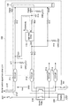
- FIG. 3 is an explanatory diagram for explaining an example of a schematic configuration of the ECU according to the present embodiment.
- the ECU 100 according to the present embodiment shows that a diode D21 is provided instead of the diode D11 and a resistor R21 may be provided. 1 is different from the ECU 500 according to the comparative example described with reference to FIG.
- the diode D21 is provided so as to electrically connect the node n11 and the node n21 located on the input side of the high-side driver 110. That is, the node n11 and the node n21 are bypassed via the diode D21.
- the diode D21 is connected so that a signal is supplied from the node n11 toward the node n21. That is, even if a reverse current is generated from the node n21 toward the node n11, the reverse current is shielded by the diode D21.
- a resistor R21 may be provided between the node n21 and the input terminal IN of the high side driver 110.
- the high side driver 110 corresponds to an example of a “drive circuit” that drives the starter relay.
- an instruction signal (Starter switch signal) relating to an instruction to drive the starter 230 is supplied from an external ECU to the ECU pin P11, and the clutch switch is controlled to be in a conductive state.
- the instruction signal input to the ECU pin P11 is demultiplexed at the node n11.
- a part of the demultiplexed instruction signal is bypassed toward the node n21 via the diode D21 and is input to the input terminal of the high side driver 110 via the resistor R21.
- the high side driver 110 is driven based on the instruction signal supplied to the input terminal, and a drive signal is supplied from the high side driver 110 to the relay coil of the starter relay 210 via the diode D12 and the ECU pin P12.
- the drive signal is supplied to the relay coil of the starter relay 210 through the path indicated by the reference symbol C13.
- the relay contact of the starter relay 210 is controlled to be in a conductive state, and power is supplied from the power source (BAT) to the starter 230, so that the starter 230 is driven.
- the instruction signal supplied to the input terminal IN of the high-side driver 110 via the diode D21 corresponds to an example of “first signal”.
- the drive signal supplied from the high-side driver 110 to the starter relay 210 corresponds to an example of “second signal”.
- the resistor R21 limits the current flowing through the diode D21 by configuring the resistor R21 in series with the diode D21 as necessary. Is also possible.
- a low breakdown voltage element that is, an element having a small size
- the ECU 100 is configured to drive the high-side driver 110 based on an instruction signal supplied from an external ECU, and to drive the starter relay 210 using a drive signal output from the high-side driver 110. ing. That is, in the ECU 100 according to the present embodiment, it is possible to output a drive signal having a predetermined level from the high side driver 110 regardless of the level of the signal input to the high side driver 110. Therefore, for example, even if a voltage drop occurs due to the resistor R21, if the high-side driver 110 can be driven, the starter relay 210 can be driven regardless of the influence of the voltage drop.
- the CPU 130 can recognize an instruction regarding driving of the starter 230 from an external ECU, and can execute various controls regarding driving of the starter 230.
- a drive signal is supplied to the relay coil of the starter relay 210 via the path indicated by reference numeral C12.
- a signal supplied to the high side driver 110 so that the CPU 130 drives the high side driver 110 corresponds to an example of a “third signal”.
- FIG. 4 is a block diagram showing an example of a configuration of a high side driver applied in the ECU according to the present embodiment.
- the high-side driver 110 includes an ESD (Electro-Static Discharge) 111, a control unit (Logic) 112, and a charge pump level shifter rectifier (Charge pump Level shifter Rectifier) 113. And an unclamped limiting unit (Limit for unclamped ind. Loads) 114, a current limiting unit (Current Limit) 115, a gate protection unit (Gate protection) 116, a transistor 117, a temperature sensor (Temperature sensor) 119, , A voltage source 121 and an overvoltage protection unit 122.
- ESD Electro-Static Discharge
- Logic Control unit
- a charge pump level shifter rectifier Charge pump Level shifter Rectifier
- the transistor 117 is constituted by, for example, a MOSFET (Metal-Oxide-Semiconductor Field-Effect Transistor) or the like, and a feedback diode 118 is connected in antiparallel to constitute a switching circuit.
- the power supply voltage (+ Vbb) is applied to the drain terminal side, and the output terminal OUT of the high side driver 110 is electrically connected to the source terminal side. That is, when a voltage is applied to the gate terminal of the transistor 117 and the transistor 117 becomes conductive, a drive signal corresponding to the power supply voltage (+ Vbb) is output from the output terminal OUT to the outside of the high side driver 110.
- IGSW ignition switch
- the potential of the output terminal OUT is determined by a load (resistance) indicated by reference numeral 123.
- the voltage source 121 is driven based on the power supply voltage (+ Vbb) and applies a voltage V Logic for driving the control unit 112 to the control unit 112.
- the overvoltage protection unit 122 is provided to protect the voltage source 121 from overvoltage.
- the ESD 111 is configured to protect the circuits and elements inside the high-side driver 110 from electrostatic discharge.
- An input signal input to the input terminal IN of the high side driver 110 is input to the control unit 112 via the ESD 111.
- the temperature sensor 119 is configured to detect the temperature inside the high side driver 110.
- the temperature sensor 119 outputs information indicating the detection result of the temperature to the control unit 112.
- the control unit 112 drives the charge pump level shifter rectifying unit 113 located in the subsequent stage according to whether the level of the input signal input from the input terminal IN via the ESD 111 is high or low.
- the control unit 112 drives the charge pump level shifter rectifier 113 by supplying a drive signal to the charge pump level shifter rectifier 113 when the level of the input signal is high.
- control unit 112 may control driving of the charge pump level shifter rectifying unit 113 according to the temperature detection result by the temperature sensor 119.
- control unit 112 may limit the drive of the charge pump level shifter rectifying unit 113 when the temperature inside the high-side driver 110 is equal to or higher than a threshold value.
- the charge pump level shifter rectifying unit 113 boosts the supplied drive signal and supplies the boosted drive signal to the gate terminal of the transistor 117. That is, when the drive signal is supplied from the charge pump level shifter rectifier 113 to the gate terminal of the transistor 117, the transistor 117 is controlled to be in a conductive state. Note that a gate protection portion 116 is provided on the gate terminal side of the transistor 117 to protect the gate terminal when an abnormality such as a failure occurs.
- the unclamped limiting unit 114 and the current limiting unit 115 are limiters for limiting the output of the drive signal from the output terminal OUT.
- the unclamped limiting unit 114 operates as a limiter for preventing the occurrence of an abnormality associated with inductive loads without clamping the output signal.
- the current limiter 115 operates as a limiter for preventing the outflow of overcurrent from the output terminal due to a failure of the system on the output terminal OUT side or the like.
- the current limiting unit 115 limits the supply of the drive signal to the gate terminal of the transistor 117. To do. As a result, the transistor 117 is turned off and the output of the drive signal from the output terminal OUT is cut off.
- the supply of the power supply voltage (+ Vbb) to the high side driver 110 is controlled by the ignition switch. Therefore, the high-side driver 110 according to the present embodiment can stop the output of the drive signal from the output terminal OUT by the ignition switch regardless of the input state of the input signal to the input terminal IN. .
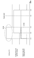
- FIG. 5 is a timing chart showing an example of the drive timing of the starter relay 210 when the ECU 100 according to the present embodiment is interposed.
- the horizontal axis represents time.
- the timing chart shown in the upper part of FIG. 5 shows the timing of signal supply from the external ECU to the ECU pin P11.
- the timing chart shown in the middle section shows the supply timing of the drive signal output from the high side driver 110 based on the control by the CPU 130.
- the timing chart shown in the lower part shows the supply timing of the signal output from the ECU pin P12 and supplied to the relay coil of the starter relay 210.
- an instruction signal (Starter switch signal) related to an instruction to drive the starter 230 is supplied from the external ECU to the ECU pin P11, and the clutch switch Is controlled to be in a conductive state.
- an instruction signal is supplied from an external ECU to the ECU pin P11 during a period indicated by reference numerals t11 to t13.
- part of the instruction signal that is input to the ECU pin P11 and demultiplexed at the node n11 is input to the input terminal of the high-side driver 110 via the diode D21 and the resistor R21. Input to IN.
- the high side driver 110 is driven, and a drive signal output from the output terminal OUT of the high side driver 110 is supplied to the relay coil of the starter relay 210. That is, in the ECU 100 according to the present embodiment, a drive signal is supplied to the relay coil of the starter relay 210 via the path C13 during the period indicated by reference numerals t11 to t13.
- the relay contact of the starter relay 210 is controlled to be in a conductive state at timing t11, and power is supplied from the power source (BAT) to the starter 230, so that the starter 230 is driven.
- the CPU 130 may drive the high side driver 110 by supplying a drive signal to the high side driver 110 based on an instruction from an external ECU.
- a drive signal is supplied to the relay coil of the starter relay 210 via the path indicated by reference numeral C12.
- the drive signal is supplied from the high-side driver 110 to the starter relay 210 based on the control from the CPU 130 at the timing indicated by the reference symbol t12. Has been started.
- the internal combustion engine is started at the timing indicated by reference numeral t14, and the supply of the drive signal from the high side driver 110 to the starter relay 210 is performed at the timing indicated by reference numeral t15. Has stopped at.
- the signal of the portion indicated by the reference symbol S103 is supplied by the high side driver 110. Therefore, for example, even when some abnormality such as a failure occurs in the period from timing t11 to t13, the supply of the drive signal to the starter relay 210 can be limited by various limiters provided in the high side driver 110. It becomes.
- the ECU 100 includes the ECU pin P11, the high side driver 110, and the diode D21.
- the ECU pin P11 is supplied with a control signal (for example, an instruction signal) from another unit (for example, another ECU).
- the diode D21 is connected so that the control signal is supplied from the ECU pin P11 toward the input terminal IN of the high-side driver 110.
- the high side driver 110 drives the starter relay 210 by supplying a drive signal to the starter relay 210 based on the input control signal. Due to the above configuration, the ECU 100 according to the present embodiment starts the internal combustion engine because the high-side driver 110 is driven based on the instruction signal from the external ECU even when the CPU 130 is difficult to operate. It is possible to make it.
- the ECU 100 according to the present embodiment can limit the current flowing through the diode D21 by the resistor R21 by configuring the resistor R21 in series with the diode D21 as necessary. is there.
- a low breakdown voltage element that is, a small-sized element
- the ECU 100 according to the present embodiment can be realized in a smaller size and at a lower cost than the ECU 500 according to the comparative example described above, for example.
- the degree of freedom in design is improved.
- the high side driver 110 is driven based on the control signal supplied from the external unit, and the starter relay 210 is driven by the drive signal output from the high side driver 110. It is configured to drive. Therefore, in this embodiment, in the ECU 100, the resistor R21 is connected in series to the diode D21, so that even if a voltage drop occurs due to the resistor R21, the starter relay is independent of the influence of the voltage drop. 210 can be driven.
- the drive signals to the starter relay 210 are provided by various limiters provided in the high side driver 110. Can be limited. Therefore, according to the ECU 100 of the present embodiment, for example, when a situation in which an overcurrent is output as a drive signal to the starter relay 210 is detected, the supply of the drive signal is restricted by the control of the ECU 100. It becomes possible to do. Further, in the ECU 100 according to the present embodiment, the output of the drive signal from the high-side driver 110 to the starter relay 210 can be stopped by the ignition switch regardless of the supply status of the control signal from other units. is there.
Landscapes
- Engineering & Computer Science (AREA)
- Chemical & Material Sciences (AREA)
- Combustion & Propulsion (AREA)
- Mechanical Engineering (AREA)
- General Engineering & Computer Science (AREA)
- Combined Controls Of Internal Combustion Engines (AREA)
Abstract
他のユニットから供給される制御信号を利用することで、内燃機関を始動させるスタータの動作の制御を、より好適な態様で実現する。 他のユニットから第1の信号が供給される入力端子(P11)と、駆動回路(110)と、前記入力端子(P11)から前記駆動回路(110)の入力側に向けて前記第1の信号が供給されるように接続されたダイオード(D21)と、を備え、前記駆動回路(110)は、入力される前記第1の信号に基づきスタータリレー(210)に対して第2の信号を供給することで当該スタータリレーを駆動する、制御装置。
Description
本発明は、制御装置に関する。
自動車の内燃機関は、単独で始動することが困難であるため、例えば、スタータを利用して始動される場合がある。スタータとしては、例えば、電気的に駆動されるスタータモータが設けられたものが一般的に知られている。具体的には、当該スタータモータは、所謂噛み合わせリレーとして構成されたスタータリレーを介して電源接続される。このような構成の基で、スタータリレーに対して駆動信号が供給されると、電源からスタータに電力が供給され、当該スタータモータが駆動して内燃機関を始動させる。
また、自動車の各種動作を制御する場合において、複数の電子制御装置(ECU:Electronic Control Unit)が連携して動作する場合も少なくない。例えば、内燃機関を始動させるための構成に着目した場合には、内燃機関の始動を制御するためのECUが、主となる制御を行う他のユニット(例えば、他のECU)からの制御信号に基づき従属的に動作することで、スタータを駆動する場合がある。
例えば、特許文献1には、スタータリレーを駆動するための駆動回路の動作をマイコン等の制御部により制御することで、内燃機関を始動させる構成の一例が開示されている。
一方で、内燃機関の始動を制御するためのECUの制御部に何らかの異常が生じ、当該制御部が動作することが困難な状況が発生した場合には、スタータを駆動することが困難となる場合が想定され得る。このような状況から、当該ECUの制御部に何らかの異常が生じた場合においても、他のユニットから供給される制御信号に基づき、スタータの駆動を可能とするための仕組みの導入が求められている。
そこで、本発明は、上記問題に鑑みてなされたものであり、本発明の目的とするところは、他のユニットから供給される制御信号を利用することで、内燃機関を始動させるスタータの動作の制御を、より好適な態様で実現することが可能な制御装置を提供することにある。
上記課題を解決するために、本発明のある観点によれば、他のユニットから第1の信号が供給される入力端子(P11)と、駆動回路(110)と、前記入力端子(P11)から前記駆動回路(110)の入力側に向けて前記第1の信号が供給されるように接続されたダイオード(D21)と、を備え、前記駆動回路(110)は、入力される前記第1の信号に基づきスタータリレー(210)に対して第2の信号を供給することで当該スタータリレーを駆動する、制御装置が提供される。
以上説明したように本発明によれば、他のユニットから供給される制御信号に基づき、内燃機関を始動させるスタータの動作の制御をより好適な態様で実現することが可能な制御装置が提供される。
以下に添付図面を参照しながら、本発明の好適な実施の形態について詳細に説明する。なお、本明細書及び図面において、実質的に同一の機能構成を有する構成要素については、同一の符号を付することにより重複説明を省略する。
<<1.はじめに>>
まず、内燃機関の始動の制御に係るECUの構成の一例と、当該ECUが介在した内燃機関の始動の制御の一例と、について比較例としてそれぞれ説明したうえで、本発明の技術的課題について整理する。
まず、内燃機関の始動の制御に係るECUの構成の一例と、当該ECUが介在した内燃機関の始動の制御の一例と、について比較例としてそれぞれ説明したうえで、本発明の技術的課題について整理する。
<1.1.比較例に係るECU>
複数のECUが連携して動作する構成の一例として、内燃機関の始動を制御するためのECUが、主となる制御を行う他のユニット(例えば、他のECU)からの制御信号に基づき従属的に動作することで、スタータを駆動する構成が挙げられる。一方で、内燃機関の始動を制御するためのECUの制御部に何らかの異常が生じ、当該制御部が動作することが困難な状況が発生した場合には、スタータを駆動することが困難となる場合が想定され得る。このような状況から、当該ECUの制御部に何らかの異常が生じた場合においても、他のユニットから供給される制御信号に基づき、スタータの駆動を可能とするための仕組みの導入が求められている。
複数のECUが連携して動作する構成の一例として、内燃機関の始動を制御するためのECUが、主となる制御を行う他のユニット(例えば、他のECU)からの制御信号に基づき従属的に動作することで、スタータを駆動する構成が挙げられる。一方で、内燃機関の始動を制御するためのECUの制御部に何らかの異常が生じ、当該制御部が動作することが困難な状況が発生した場合には、スタータを駆動することが困難となる場合が想定され得る。このような状況から、当該ECUの制御部に何らかの異常が生じた場合においても、他のユニットから供給される制御信号に基づき、スタータの駆動を可能とするための仕組みの導入が求められている。
例えば、図1は、比較例に係るECUの概略的な構成の一例について説明するための説明図であり、当該ECUの制御部に何らかの異常が生じた場合においても、他のユニットから供給される制御信号に基づき、スタータの駆動を可能とするための構成の一例を示している。
具体的には、比較例に係るECU500は、電力源(BAT)からスタータ(Starter)230への電力の供給を制御する。具体的には、ECU500は、電力源とスタータ230との間に介在するように設けられたスタータリレー(Starter Relay)210のリレーコイルに対する駆動信号の供給の有無を制御することで、当該スタータリレー210のリレー接点(スイッチ)を導通状態と非導通状態との間で切り替える。このような構成の基で、スタータリレー210のリレー接点が導通状態に制御された場合には、電力源からスタータ230に対して電力が供給される。また、スタータリレー210のリレー接点が非導通状態に制御された場合には、電力源からスタータ230への電力の供給が遮断される。
ここで、比較例に係るECU500の構成についてさらに詳しく説明する。図1に示すように、ECU500は、ECUピンP11及びP12と、CPU130と、ハイサイドドライバ110と、を含む。
ECUピンP11は、ECU500とは異なる他のユニット(例えば、他のECU)からの制御信号を、当該ECU500に入力するための入力端子である。具体的な一例として、ECUピンP11には、他のECUから供給されるスタータ230の駆動の指示に係る指示信号(Starter switch signal)が入力される。ECUピンP11の電位は、当該ECUピンP11と基準電位(グラウンド)GNDとの間に介在するように設けられた抵抗R11により決定される。
ECUピンP11には、抵抗R12を介してCPU130の入力端子(Digital input)が電気的に接続される。また、CPU130の出力端子(Digital output)は、ハイサイドドライバ110の入力端子INと電気的に接続される。CPU130の出力端子の電位は、当該出力端子と基準電位GNDとの間に介在するように設けられた抵抗R13により決定される。
ハイサイドドライバ110の出力端子OUTは、ダイオードD12を介してECUピンP12に電気的に接続される。ハイサイドドライバ110の出力端子の電位は、当該出力端子と基準電位GNDとの間に介在するように設けられた抵抗R14により決定される。また、ダイオードD12は、ハイサイドドライバ110の出力端子からECUピンP12に向けて信号が供給されるように接続される。これにより、ハイサイドドライバ110から出力される信号が、ECUピンP12を介してECU500の外部に出力され、ECUピンP12からハイサイドドライバ110に向けて逆電流が生じたとしても、当該逆電流がダイオードD12により遮蔽される。
また、ハイサイドドライバ110から出力される信号は、スプリッタ等により一部の信号が分波され、当該分波された信号は、抵抗R15を介してCPU130の帰還端子(DIAG)に入力される。このような構成により、例えば、CPU130は、ハイサイドドライバ110の出力端子から出力される信号を監視し、監視結果に基づき当該ハイサイドドライバ110の入力端子への信号の供給を制御することが可能となる。
また、ECUピンP11と抵抗R12との間に位置するノードn11と、ダイオードD12とECUピンP12との間に位置するノードn13と、の間は、ダイオードD11を介して電気的に接続される。即ち、ノードn11とノードn13との間は、ダイオードD11を介してバイパスされている。なお、ダイオードD11は、ノードn11からノードn13に向けて信号が供給されるように接続される。このような構成により、ノードn13からノードn11に向けて(即ち、ECUピンP12からECUピンP11に向けて)逆電流が生じたとしても、当該逆電流がダイオードD11により遮蔽される。
ECUピンP12は、スタータリレー210のリレー接点の一方の端子に電気的に接続されている。また、当該リレー接点の他方の端子は、クラッチスイッチ(Clutch SW)を介して接地点(アース)に接続されている。
また、ECU500には、図1に示すように、ECUピンP13及びP14のうち少なくともいずれかが設けられていてもよい。
ECUピンP13は、電力源(BAT)からスタータリレー210のリレー接点を介してスタータ230に供給される信号(電力)の一部をスプリッタ等により分波し、当該一部の信号をECU500に入力する(即ち、フィードバックする)ための入力端子である。このような構成により、例えば、CPU130は、ECUピンP13から入力された信号に基づき、スタータ230への電力供給の状態を監視することが可能となる。
また、ECUピンP14は、スタータリレー210のリレーコイルに対して供給された信号の一部を分波し、当該一部の信号をECU500に入力する(即ち、フィードバックする)ための入力端子である。このような構成により、例えば、CPU130は、ECUピンP14から入力された信号に基づき、スタータリレー210のリレーコイルに対する信号供給の状態を監視することが可能となる。
続いて、図1及び図2を参照して、比較例に係るECU500が介在した、スタータリレー210の制御の一例について説明する。
例えば、外部のECUからECUピンP11に、スタータ230の駆動の指示に係る指示信号(Starter switch signal)が供給され、クラッチスイッチが導通状態に制御されたものとする。
この場合には、図1に示すように、ECUピンP11に入力された指示信号がノードn11で分波される。分波された指示信号の一部は、ダイオードD11を介してノードn13に向けてバイパスされて、ECUピンP12からECU500の外部に出力され、スタータリレー210のリレーコイルに供給される。即ち、参照符号C11で示された経路を介して、スタータリレー210のリレーコイルに駆動信号が供給されることとなる。これにより、タイミングt11においてスタータリレー210のリレー接点が導通状態に制御され、電力源(BAT)からスタータ230に電力が供給されるため、当該スタータ230が駆動することとなる。
また、ノードn11で分波された指示信号の他の一部は、抵抗R12を介してCPU130に供給される。これにより、CPU130は、外部のECUからのスタータ230の駆動に関する指示を認識し、スタータ230の駆動に係る各種制御を実行することが可能となる。より具体的な一例として、CPU130は、外部のECUからの指示に基づき、ハイサイドドライバ110に駆動信号を供給することで、当該ハイサイドドライバ110を駆動してもよい。この場合には、参照符号C12で示された経路を介して、スタータリレー210のリレーコイルに駆動信号が供給されることとなる。これにより、ハイサイドドライバ110からスタータリレー210のリレーコイルに駆動信号が供給されるため、外部のECUからの指示信号に基づき内燃機関が始動しなかったとしても、ハイサイドドライバ110から供給される駆動信号に基づき、当該内燃機関の始動をアシストすることが可能となる。また、このときCPU130は、例えば、ECUピンP13及びP14にフィードバックされる各信号に基づき、スタータ230やスタータリレー210の駆動状態を監視し、監視結果に応じてハイサイドドライバ110を駆動してもよい。
ここで、図2を参照して、図1に示す例において、経路C11を介したスタータ230への信号の供給タイミングと、CPU130による制御に基づくハイサイドドライバ110から当該スタータ230への信号の供給タイミングと、の関係について説明する。図2は、比較例に係るECU500が介在した場合における、スタータリレー210の駆動タイミングの一例について示したタイミングチャートである。図2において、横軸は時間を示している。また、図2の上段に示したタイミングチャートは、外部のECUからECUピンP11への信号の供給タイミングを示している。また、中段に示したタイミングチャートは、CPU130による制御に基づきハイサイドドライバ110から出力される駆動信号の供給タイミングを示している。また、下段に示したタイミングチャートは、ECUピンP12から出力されスタータリレー210のリレーコイルに供給される信号の供給タイミングを示している。換言すると、下段に示したタイミングチャートは、スタータリレー210のリレー接点が導通状態と非導通状態との間で切り替わるタイミングを示している。なお、スタータリレー210のリレー接点は、当該スタータリレー210のリレーコイルに供給される信号のレベルがハイレベルを示す場合に、導通状態に制御されるものとする。
例えば、図2に示す例では、参照符号t11からt13で示された期間中に、外部のECUからECUピンP11に指示信号が供給される。即ち、当該期間中に、ECUピンP11から経路C11を介して当該指示信号の一部がスタータリレー210のリレーコイルに供給され、当該指示信号の他の一部がCPU130に供給される。CPU130は、他のECUからの指示信号が供給されると、当該指示信号の供給が停止する前に、ハイサイドドライバ110を駆動する。例えば、図2に示す例では、参照符号t12で示されたタイミングで、ハイサイドドライバ110からスタータリレー210への駆動信号の供給が開始されている。なお、図2に示す例では、参照符号t14で示されたタイミングで内燃機関が始動しており、ハイサイドドライバ110からスタータリレー210への駆動信号の供給は、参照符号t15で示されたタイミングで停止されている。
以上説明したように、比較例に係るECU500は、タイミングt11からt13で示された期間に外部のECUからECUピンP11に供給される指示信号をスタータリレー210の駆動に利用する。そのため、例えば、CPU130に何らかの異常が発生し、当該CPU130が動作することが困難な場合においても、外部のECUからの指示信号により内燃機関を始動させることが可能である。
また、図2において参照符号S101で示された部分の信号、即ち、外部のECUからECUピンP11に供給される指示信号については、ECU500による制御が困難である。一方で、外部のECUから供給される指示信号のみでは内燃機関が始動しない場合もある。より具体的な一例として、常温時において外部のECUから供給される指示信号のみで内燃機関を始動させることが可能であったとしても、寒冷地においては、当該指示信号のみでは内燃機関を始動しきれない場合も想定され得る。これに対して、比較例に係るECU500では、CPU130が、外部のECUからECUピンP11に供給される指示信号に基づき、ハイサイドドライバ110からスタータリレー210への駆動信号の供給を制御する。そのため、例えば、図2に示す例のように、外部のECUから供給される指示信号のみでは内燃機関が始動しきれない場合においても、ハイサイドドライバ110から駆動信号を供給することで、内燃機関の始動をアシストすることが可能となる。
以上、図1及び図2を参照して、比較例に係るECU500の構成の一例と、当該ECU500が介在したスタータリレー210の制御の一例と、についてそれぞれ説明した。
<1.2.技術的課題>
続いて、本発明の技術的課題として、特に、図1及び図2を参照して説明した比較例に係るECU500における技術的課題について以下に説明する。
続いて、本発明の技術的課題として、特に、図1及び図2を参照して説明した比較例に係るECU500における技術的課題について以下に説明する。
図1を参照して説明したように、比較例に係るECU500では、ECUピンP11に入力された指示信号が、ダイオードD11が設けられたバイパス経路を介してECUピンP12から当該ECU500の外部に出力される。このような構成の基で、例えば、ECUピンP12が何らかの故障によりグラウンドショートした状態において、外部のECUからECUピンP11に指示信号が供給されると、ECUピンP11の電位に相当する電圧VonがダイオードD11に印加され、当該ダイオードD11に過電流が流れる場合がある。そのため、例えば、当該過電流の流入によりダイオードD11が破損する場合も想定され得る。
このような状況を鑑み、ダイオードD11として高耐圧の素子を使用することで、過電流による当該ダイオードD11の破損を防止する対策が考えられる。しかしながら、ダイオードD11として採用される素子は、高耐圧のものほど内部の構成が複雑化し、サイズもより大きくなる傾向にある。そのため、例えば、ダイオードD11として高耐圧の素子を適用すると、当該ダイオードD11を既存のECU500の筐体内におさめることが困難となり、ひいてはECU500を大型化せざるを得なくなる場合もある。これに対して、自動車の内部に設けられるECUは、設置スペースが限られているため装置の大型化が望ましくなく、ダイオードD11として大型のものを適用すると、ECU500を自動車内に設置することが困難となる状況も想定され得る。また、ダイオードD11として採用される素子は、高耐圧のものほどより高価になる傾向にある。そのため、ダイオードD11として高耐圧の素子を適用することで、ECU500を実現するためのコストの増加も想定され得る。
また、過電流の流入を想定して、ダイオードD11に対して直列に抵抗を接続することで、当該ダイオードD11に流れる電流を制限することにより、当該ダイオードD11として低耐圧の素子(即ち、サイズの小さい素子)を使用する対策も考えられる。しかしながら、ダイオードD11に対して直列に抵抗が接続されると、当該抵抗により電圧降下が生じ、当該ダイオードD11を介して供給される制御信号(即ち、他のECUから供給される指示信号)により、スタータリレー210を駆動することが困難となる場合がある。
このような状況を鑑み、本発明では、他のECUから供給される制御信号をスタータリレー210の駆動に利用可能なECUを、小型かつ安価に実現可能とする仕組みについて提案する。
<<2.実施形態>>
以下に、本発明の実施形態に係るECUの技術的特徴についてまとめる。
以下に、本発明の実施形態に係るECUの技術的特徴についてまとめる。
<2.1.ECUの構成>
まず、図3を参照して、本実施形態に係るECUの構成の一例について説明する。図3は、本実施形態に係るECUの概略的な構成の一例について説明するための説明図である。なお、図3と図1とを比較するとわかるように、本実施形態に係るECU100は、ダイオードD11に替えてダイオードD21が設けられている点と、抵抗R21が設けられてもよい点が、図1を参照して説明した比較例に係るECU500と異なる。そこで、本説明では、本実施形態に係るECU100の構成の一例について、前述した比較例に係るECU500と異なる部分に着目して説明し、当該ECU500と実質的に同様の部分については詳細な説明は省略する。
まず、図3を参照して、本実施形態に係るECUの構成の一例について説明する。図3は、本実施形態に係るECUの概略的な構成の一例について説明するための説明図である。なお、図3と図1とを比較するとわかるように、本実施形態に係るECU100は、ダイオードD11に替えてダイオードD21が設けられている点と、抵抗R21が設けられてもよい点が、図1を参照して説明した比較例に係るECU500と異なる。そこで、本説明では、本実施形態に係るECU100の構成の一例について、前述した比較例に係るECU500と異なる部分に着目して説明し、当該ECU500と実質的に同様の部分については詳細な説明は省略する。
図3に示すように、ダイオードD21は、ノードn11と、ハイサイドドライバ110の入力側に位置するノードn21と、の間を電気的に接続するように設けられる。即ち、ノードn11とノードn21との間は、ダイオードD21を介してバイパスされている。なお、ダイオードD21は、ノードn11からノードn21に向けて信号が供給されるように接続される。即ち、ノードn21からノードn11に向けて逆電流が生じたとしても、当該逆電流がダイオードD21により遮蔽される。また、ノードn21と、ハイサイドドライバ110の入力端子INと、の間には、抵抗R21が設けられてもよい。なお、ハイサイドドライバ110が、スタータリレーを駆動する「駆動回路」の一例に相当する。
ここで、外部のECUからECUピンP11に、スタータ230の駆動の指示に係る指示信号(Starter switch signal)が供給され、クラッチスイッチが導通状態に制御されたものとする。
この場合には、まず、前述した比較例に係るECU500と同様に、ECUピンP11に入力された当該指示信号がノードn11で分波される。一方で、本実施形態に係るECU100においては、分波された指示信号の一部は、ダイオードD21を介してノードn21に向けてバイパスされて、抵抗R21を介してハイサイドドライバ110の入力端子に供給される。次いで、入力端子に供給された指示信号に基づきハイサイドドライバ110が駆動し、当該ハイサイドドライバ110からダイオードD12及びECUピンP12を介して、スタータリレー210のリレーコイルに駆動信号が供給される。即ち、参照符号C13で示された経路を介して、スタータリレー210のリレーコイルに駆動信号が供給されることとなる。これにより、スタータリレー210のリレー接点が導通状態に制御され、電力源(BAT)からスタータ230に電力が供給されるため、当該スタータ230が駆動することとなる。なお、ダイオードD21を介してハイサイドドライバ110の入力端子INに供給される指示信号が「第1の信号」の一例に相当する。また、ハイサイドドライバ110からスタータリレー210に供給される駆動信号が「第2の信号」の一例に相当する。
ここで、経路C13に着目すると、ダイオードD21には、外部のECUから供給される駆動信号、即ち、ECU100による制御が困難な信号が直接流入する構成となっている。これに対して、本実施形態に係るECU100では、必要に応じて、ダイオードD21に対して抵抗R21が直列に接続される構成とすることで、当該ダイオードD21に流れる電流を抵抗R21により制限することも可能である。これにより、本実施形態に係るECU100に依れば、当該ダイオードD21として低耐圧の素子(即ち、サイズの小さい素子)を使用することが可能となるため、例えば、ECU100の大型化を抑制することが可能となり、設計の自由度も向上する。また、本実施形態に係るECU100では、外部のECUから供給される指示信号に基づきハイサイドドライバ110を駆動し、当該ハイサイドドライバ110から出力される駆動信号によりスタータリレー210を駆動する構成となっている。即ち、本実施形態に係るECU100においては、ハイサイドドライバ110に入力される信号のレベルに関わらず、当該ハイサイドドライバ110から所定のレベルの駆動信号を出力することが可能である。そのため、例えば、抵抗R21により電圧降下が生じたとしても、ハイサイドドライバ110を駆動することが可能であれば、当該電圧降下の影響に関わらずスタータリレー210を駆動することが可能となる。
また、ノードn11で分波された指示信号の他の一部は、抵抗R12を介してCPU130に供給される。これにより、前述した比較例に係るECU500と同様に、CPU130は、外部のECUからのスタータ230の駆動に関する指示を認識し、スタータ230の駆動に係る各種制御を実行することが可能となる。なお、この場合には、参照符号C12で示された経路を介して、スタータリレー210のリレーコイルに駆動信号が供給されることとなる。また、CPU130がハイサイドドライバ110を駆動するために、当該ハイサイドドライバ110に供給する信号が「第3の信号」の一例に相当する。
以上、図3を参照して、本実施形態に係るECUの構成の一例について説明した。
<2.2.ハイサイドドライバの構成>
続いて、図4を参照して、本実施形態に係るECUにおいて適用されるハイサイドドライバの構成の一例について説明する。図4は、本実施形態に係るECUにおいて適用されるハイサイドドライバの構成の一例を示したブロック図である。
続いて、図4を参照して、本実施形態に係るECUにおいて適用されるハイサイドドライバの構成の一例について説明する。図4は、本実施形態に係るECUにおいて適用されるハイサイドドライバの構成の一例を示したブロック図である。
図4に示すように、本実施形態に係るハイサイドドライバ110は、ESD(Electro-Static Discharge)111と、制御部(Logic)112と、チャージポンプレベルシフター整流部(Charge pump Level shifter Rectifier)113と、アンクランプド制限部(Limit for unclamped ind. loads)114と、電流制限部(Current Limit)115と、ゲート保護部(Gate protection)116と、トランジスタ117と、温度センサ(Temperature sensor)119と、電圧源(Voltage source)121と、過電圧保護部(Overvoltage protection)122と、を含む。
トランジスタ117は、例えば、MOSFET(Metal-Oxide-Semiconductor Field-Effect Transistor)等により構成され、帰還ダイオード118が逆並列に接続されてスイッチング回路を構成している。トランジスタ117は、ドレイン端子側には電源電圧(+Vbb)が印加され、ソース端子側にはハイサイドドライバ110の出力端子OUTが電気的に接続されている。即ち、トランジスタ117のゲート端子に電圧が印加され当該トランジスタ117が導通状態となると、電源電圧(+Vbb)に応じた駆動信号が、当該出力端子OUTからハイサイドドライバ110の外部に出力される。なお、電源電圧(+Vbb)の印加の有無は、イグニッションスイッチ(IGSW)により選択的に制御される。なお、当該出力端子OUTの電位は、参照符号123で示された負荷(抵抗)により決定される。
電圧源121は、電源電圧(+Vbb)に基づき駆動し、制御部112が駆動するための電圧VLogicを当該制御部112に印加する。また、過電圧保護部122は、電圧源121を過電圧から保護するために設けられている。
ESD111は、静電気放電からハイサイドドライバ110の内部の回路や素子を保護するための構成である。ハイサイドドライバ110の入力端子INに入力された入力信号は、ESD111を介して制御部112に入力される。
温度センサ119は、ハイサイドドライバ110の内部の温度を検出するための構成である。温度センサ119は、当該温度の検出結果を示す情報を制御部112に出力する。
制御部112は、入力端子INからESD111を介して入力される入力信号のレベルがハイ及びローのいずれかに応じて、後段に位置するチャージポンプレベルシフター整流部113を駆動する。具体的な一例として、制御部112は、入力信号のレベルがハイの場合に、チャージポンプレベルシフター整流部113に駆動信号を供給することで、当該チャージポンプレベルシフター整流部113を駆動する。
また、制御部112は、温度センサ119による温度の検出結果に応じて、チャージポンプレベルシフター整流部113の駆動を制御してもよい。具体的な一例として、制御部112は、ハイサイドドライバ110の内部の温度が閾値以上の場合には、チャージポンプレベルシフター整流部113の駆動を制限してもよい。
チャージポンプレベルシフター整流部113は、制御部112から駆動信号が供給されると、供給された駆動信号を昇圧し、昇圧された駆動信号をトランジスタ117のゲート端子に供給する。即ち、チャージポンプレベルシフター整流部113からトランジスタ117のゲート端子に駆動信号が供給されることで、当該トランジスタ117が導通状態に制御される。なお、トランジスタ117のゲート端子側には、故障等の異常が発生した場合に、当該ゲート端子を保護するゲート保護部116が設けられている。
また、アンクランプド制限部114及び電流制限部115は、出力端子OUTからの駆動信号の出力を制限するためのリミッタである。具体的には、アンクランプド制限部114は、誘導性負荷(inductive loads)に伴う異常の発生を、出力信号をクランプさせずに防止するためのリミッタとして動作する。また、電流制限部115は、出力端子OUT側の系の故障等に伴い、当該出力端子からの過電流の流出を防止するためのリミッタとして動作する。具体的な一例として、負荷123等の破損に伴い出力端子OUTから過電流が出力されるような状況が検出されると、電流制限部115がトランジスタ117のゲート端子への駆動信号の供給を制限する。これにより、トランジスタ117が非導通状態となり、出力端子OUTからの駆動信号の出力が遮断される。
また、前述したように、ハイサイドドライバ110への電源電圧(+Vbb)の供給はイグニッションスイッチにより制御される。そのため、本実施形態に係るハイサイドドライバ110は、入力端子INへの入力信号の入力状況に関わらず、イグニッションスイッチにより、出力端子OUTからの駆動信号の出力を停止することが可能となっている。
以上、図4を参照して、本実施形態に係るECUにおいて適用されるハイサイドドライバの構成の一例について説明した。
<2.3.ECUによる制御>
続いて、図3及び図5を参照して、本実施形態に係るECU100が介在した、スタータリレー210の制御の一例について説明する。図5は、本実施形態に係るECU100が介在した場合における、スタータリレー210の駆動タイミングの一例について示したタイミングチャートである。図5において、横軸は時間を示している。また、図5の上段に示したタイミングチャートは、外部のECUからECUピンP11への信号の供給タイミングを示している。また、中段に示したタイミングチャートは、CPU130による制御に基づきハイサイドドライバ110から出力される駆動信号の供給タイミングを示している。また、下段に示したタイミングチャートは、ECUピンP12から出力されスタータリレー210のリレーコイルに供給される信号の供給タイミングを示している。
続いて、図3及び図5を参照して、本実施形態に係るECU100が介在した、スタータリレー210の制御の一例について説明する。図5は、本実施形態に係るECU100が介在した場合における、スタータリレー210の駆動タイミングの一例について示したタイミングチャートである。図5において、横軸は時間を示している。また、図5の上段に示したタイミングチャートは、外部のECUからECUピンP11への信号の供給タイミングを示している。また、中段に示したタイミングチャートは、CPU130による制御に基づきハイサイドドライバ110から出力される駆動信号の供給タイミングを示している。また、下段に示したタイミングチャートは、ECUピンP12から出力されスタータリレー210のリレーコイルに供給される信号の供給タイミングを示している。
なお、本説明では、図2を参照して説明した比較例と同様に、外部のECUからECUピンP11に、スタータ230の駆動の指示に係る指示信号(Starter switch signal)が供給され、クラッチスイッチが導通状態に制御されたものとする。具体的には、図2に示す例と同様に、参照符号t11からt13で示された期間中に、外部のECUからECUピンP11に指示信号が供給される。
前述したように、本実施形態に係るECU100では、ECUピンP11に入力されてノードn11で分波された指示信号の一部は、ダイオードD21及び抵抗R21を介して、ハイサイドドライバ110の入力端子INに入力される。これにより、ハイサイドドライバ110が駆動し、当該ハイサイドドライバ110の出力端子OUTから出力される駆動信号が、スタータリレー210のリレーコイルに供給される。即ち、本実施形態に係るECU100では、参照符号t11からt13で示された期間中においては、経路C13を介して、スタータリレー210のリレーコイルに駆動信号が供給される。これにより、タイミングt11においてスタータリレー210のリレー接点が導通状態に制御され、電力源(BAT)からスタータ230に電力が供給されるため、当該スタータ230が駆動することとなる。
また、図2を参照して説明した比較例に係るECU500と同様に、ノードn11で分波された指示信号の他の一部は、抵抗R12を介してCPU130に供給される。即ち、CPU130は、外部のECUからの指示に基づき、ハイサイドドライバ110に駆動信号を供給することで、当該ハイサイドドライバ110を駆動してもよい。この場合には、参照符号C12で示された経路を介して、スタータリレー210のリレーコイルに駆動信号が供給されることとなる。例えば、図5に示す例では、図2に示す例と同様に、参照符号t12で示されたタイミングで、CPU130からの制御に基づき、ハイサイドドライバ110からスタータリレー210への駆動信号の供給が開始されている。なお、図5に示す例では、参照符号t14で示されたタイミングで内燃機関が始動しており、ハイサイドドライバ110からスタータリレー210への駆動信号の供給は、参照符号t15で示されたタイミングで停止している。
ここで、タイミングt11からt13の期間に着目する。図2を参照して前述した例と同様に、参照符号S101で示された部分の信号、即ち、外部のECUからECUピンP11に供給される指示信号については、ECU100による制御が困難である。そのため、比較例に係るECU500では、参照符号S103で示された部分の信号の供給、即ち、タイミングt11からt13の期間におけるスタータリレー210への信号の供給を、ECU500自身が制御することが困難であった。
これに対して、本実施形態に係るECU100では、前述したように、参照符号S103で示された部分の信号の供給がハイサイドドライバ110により行われる。そのため、例えば、タイミングt11からt13の期間において故障等の何らかの異常が発生した場合においても、ハイサイドドライバ110に設けられた各種リミッタにより、スタータリレー210への駆動信号の供給を制限することが可能となる。
以上、図3及び図5を参照して、本実施形態に係るECU100が介在した、スタータリレー210の制御の一例について説明した。
<<3.むすび>>
以上、説明したように、本開示の一実施形態に係るECU100は、ECUピンP11と、ハイサイドドライバ110と、ダイオードD21とを備える。ECUピンP11には、他のユニット(例えば、他のECU)から制御信号(例えば、指示信号)が供給される。また、ダイオードD21は、ECUピンP11からハイサイドドライバ110の入力端子IN側に向けて、上記制御信号供給されるように接続される。また、ハイサイドドライバ110は、入力された当該制御信号に基づきスタータリレー210に対して駆動信号を供給することで当該スタータリレー210を駆動する。以上のような構成のため、本実施形態に係るECU100は、CPU130が動作することが困難な場合においても、外部のECUからの指示信号に基づきハイサイドドライバ110が駆動するため、内燃機関を始動させることが可能である。
以上、説明したように、本開示の一実施形態に係るECU100は、ECUピンP11と、ハイサイドドライバ110と、ダイオードD21とを備える。ECUピンP11には、他のユニット(例えば、他のECU)から制御信号(例えば、指示信号)が供給される。また、ダイオードD21は、ECUピンP11からハイサイドドライバ110の入力端子IN側に向けて、上記制御信号供給されるように接続される。また、ハイサイドドライバ110は、入力された当該制御信号に基づきスタータリレー210に対して駆動信号を供給することで当該スタータリレー210を駆動する。以上のような構成のため、本実施形態に係るECU100は、CPU130が動作することが困難な場合においても、外部のECUからの指示信号に基づきハイサイドドライバ110が駆動するため、内燃機関を始動させることが可能である。
また、本実施形態に係るECU100は、必要に応じて、ダイオードD21に対して抵抗R21が直列に接続される構成とすることで、当該ダイオードD21に流れる電流を抵抗R21により制限することも可能である。これにより、当該ダイオードD21として低耐圧の素子(即ち、サイズの小さい素子)を使用することも可能となる。そのため、本実施形態に係るECU100は、例えば、前述した比較例に係るECU500に比べて小型かつ安価に実現することが可能である。また、ダイオードD21として小型のものを使用することが可能なため、設計の自由度も向上する。
また、本実施形態に係るECU100においては、上述の通り、外部のユニットから供給される制御信号に基づきハイサイドドライバ110を駆動し、当該ハイサイドドライバ110から出力される駆動信号によりスタータリレー210を駆動する構成となっている。そのため、本実施形態にECU100においては、ダイオードD21に対して抵抗R21を直列に接続する構成とすることで、当該抵抗R21により電圧降下が生じたとしても、当該電圧降下の影響に関わらずスタータリレー210を駆動することが可能である。
また、本実施形態に係るECU100においては、他のユニットからの制御信号の供給を制御することが困難な場合においても、ハイサイドドライバ110に設けられた各種リミッタにより、スタータリレー210への駆動信号の供給を制限することが可能である。そのため、本実施形態のECU100に依れば、例えば、スタータリレー210への駆動信号として過電流が出力されるような状況が検出された場合に、当該駆動信号の供給を当該ECU100の制御により制限することが可能となる。また、本実施形態に係るECU100においては、他のユニットからの制御信号の供給状況に関わらず、イグニッションスイッチにより、ハイサイドドライバ110からスタータリレー210への駆動信号の出力を停止することも可能である。
以上、添付図面を参照しながら本発明の好適な実施形態について詳細に説明したが、本発明はかかる例に限定されない。本発明の属する技術の分野における通常の知識を有する者であれば、特許請求の範囲に記載された技術的思想の範疇内において、各種の変更例または修正例に想到し得ることは明らかであり、これらについても、当然に本発明の技術的範囲に属するものと了解される。
100 ECU
110 ハイサイドドライバ
112 制御部
113 チャージポンプレベルシフター整流部
114 アンクランプド制限部
115 電流制限部
116 ゲート保護部
117 トランジスタ
118 帰還ダイオード
119 温度センサ
121 電圧源
122 過電圧保護部
123 負荷
130 CPU
210 スタータリレー
230 スタータ
110 ハイサイドドライバ
112 制御部
113 チャージポンプレベルシフター整流部
114 アンクランプド制限部
115 電流制限部
116 ゲート保護部
117 トランジスタ
118 帰還ダイオード
119 温度センサ
121 電圧源
122 過電圧保護部
123 負荷
130 CPU
210 スタータリレー
230 スタータ
Claims (7)
- 他のユニットから第1の信号が供給される入力端子(P11)と、
駆動回路(110)と、
前記入力端子(P11)から前記駆動回路(110)の入力側に向けて前記第1の信号が供給されるように接続されたダイオード(D21)と、
を備え、
前記駆動回路(110)は、入力される前記第1の信号に基づきスタータリレー(210)に対して第2の信号を供給することで当該スタータリレーを駆動する、
制御装置。 - 前記ダイオード(D21)と前記駆動回路(110)の入力側との間に、当該ダイオード(D21)に流れる電流を制限する抵抗(R21)を備える、請求項1に記載の制御装置。
- 前記第1の信号に基づき前記駆動回路(110)の入力側に対して前記抵抗(R21)を介して第3の信号を供給する制御部(130)を備え、
前記駆動回路(110)は、入力される前記第3の信号に基づき、前記スタータリレー(210)に対して第2の信号を供給する、
請求項2に記載の制御装置。 - 前記駆動回路(110)は、前記スタータリレー(210)に対して、前記第1の信号に基づき前記第2の信号の供給を開始した後に、前記第3の信号に基づき前記第2の信号の供給を開始する、請求項3に記載の制御装置。
- 前記制御部(130)は、前記駆動回路(110)から出力される前記第2の信号に基づき、当該駆動回路(110)への前記第3の信号の供給を制御する、請求項3または4に記載の制御装置。
- 前記駆動回路(110)は、所定の条件に基づき前記第2の信号の出力を制限するリミッタ(115)を備える、請求項1~5のいずれか一項に記載の制御装置。
- 前記駆動回路(110)による前記スタータリレーへの前記第2の信号の供給は、イグニッションスイッチ(IGSW)により制御される、請求項1~6のいずれか一項に記載の制御装置。
Priority Applications (1)
| Application Number | Priority Date | Filing Date | Title |
|---|---|---|---|
| JP2018554869A JP6731494B2 (ja) | 2016-12-06 | 2017-11-07 | 制御装置 |
Applications Claiming Priority (2)
| Application Number | Priority Date | Filing Date | Title |
|---|---|---|---|
| JP2016-237043 | 2016-12-06 | ||
| JP2016237043 | 2016-12-06 |
Publications (1)
| Publication Number | Publication Date |
|---|---|
| WO2018105288A1 true WO2018105288A1 (ja) | 2018-06-14 |
Family
ID=62491504
Family Applications (1)
| Application Number | Title | Priority Date | Filing Date |
|---|---|---|---|
| PCT/JP2017/040009 Ceased WO2018105288A1 (ja) | 2016-12-06 | 2017-11-07 | 制御装置 |
Country Status (2)
| Country | Link |
|---|---|
| JP (1) | JP6731494B2 (ja) |
| WO (1) | WO2018105288A1 (ja) |
Citations (2)
| Publication number | Priority date | Publication date | Assignee | Title |
|---|---|---|---|---|
| JP2007051646A (ja) * | 2006-10-03 | 2007-03-01 | Fujitsu Ten Ltd | 車両用遠隔始動装置 |
| JP2012225332A (ja) * | 2011-04-22 | 2012-11-15 | Denso Corp | スタータ制御装置の異常検出装置 |
-
2017
- 2017-11-07 JP JP2018554869A patent/JP6731494B2/ja active Active
- 2017-11-07 WO PCT/JP2017/040009 patent/WO2018105288A1/ja not_active Ceased
Patent Citations (2)
| Publication number | Priority date | Publication date | Assignee | Title |
|---|---|---|---|---|
| JP2007051646A (ja) * | 2006-10-03 | 2007-03-01 | Fujitsu Ten Ltd | 車両用遠隔始動装置 |
| JP2012225332A (ja) * | 2011-04-22 | 2012-11-15 | Denso Corp | スタータ制御装置の異常検出装置 |
Also Published As
| Publication number | Publication date |
|---|---|
| JPWO2018105288A1 (ja) | 2019-10-24 |
| JP6731494B2 (ja) | 2020-07-29 |
Similar Documents
| Publication | Publication Date | Title |
|---|---|---|
| JP7443679B2 (ja) | 半導体装置 | |
| JP2017192113A (ja) | 駆動装置および誘導性負荷駆動装置 | |
| JP2015008611A (ja) | Dc−dcコンバータ | |
| JP5611420B1 (ja) | Dc−dcコンバータ | |
| US10103539B2 (en) | Semiconductor device and current limiting method | |
| CN106664010A (zh) | 内部电源电路及半导体装置 | |
| EP3104527A2 (en) | Semiconductor device | |
| US20070064370A1 (en) | Semiconductor integrated circuit device, power supply apparatus, and electric appliance | |
| JP5880494B2 (ja) | スイッチング制御回路 | |
| CN111357200B (zh) | 负载驱动电路 | |
| JP3966099B2 (ja) | 電気負荷駆動装置 | |
| WO2018069123A1 (en) | A circuit protection arrangement | |
| JP6731494B2 (ja) | 制御装置 | |
| JP6326921B2 (ja) | 過電圧保護回路 | |
| US10079596B2 (en) | Semiconductor device, charge pump circuit, semiconductor system, vehicle, and control method of semiconductor device | |
| WO2015104921A1 (ja) | 車載用電子制御装置 | |
| JP7600933B2 (ja) | 電力供給装置 | |
| JP7052517B2 (ja) | 負荷駆動装置 | |
| JP7151613B2 (ja) | 制御装置 | |
| CN111279569B (zh) | 电源保护电路 | |
| JP2007027465A (ja) | リニアソレノイドの駆動回路 | |
| JP5733237B2 (ja) | 制御回路 | |
| JP6753348B2 (ja) | スイッチング素子の駆動回路 | |
| JP7610402B2 (ja) | 負荷駆動装置 | |
| JP2020022068A (ja) | 負荷駆動装置 |
Legal Events
| Date | Code | Title | Description |
|---|---|---|---|
| 121 | Ep: the epo has been informed by wipo that ep was designated in this application |
Ref document number: 17878140 Country of ref document: EP Kind code of ref document: A1 |
|
| ENP | Entry into the national phase |
Ref document number: 2018554869 Country of ref document: JP Kind code of ref document: A |
|
| NENP | Non-entry into the national phase |
Ref country code: DE |
|
| 122 | Ep: pct application non-entry in european phase |
Ref document number: 17878140 Country of ref document: EP Kind code of ref document: A1 |