WO2018101055A1 - 画像補正装置および画像補正方法 - Google Patents
画像補正装置および画像補正方法 Download PDFInfo
- Publication number
- WO2018101055A1 WO2018101055A1 PCT/JP2017/041206 JP2017041206W WO2018101055A1 WO 2018101055 A1 WO2018101055 A1 WO 2018101055A1 JP 2017041206 W JP2017041206 W JP 2017041206W WO 2018101055 A1 WO2018101055 A1 WO 2018101055A1
- Authority
- WO
- WIPO (PCT)
- Prior art keywords
- image
- blur
- pair
- captured
- camera
- Prior art date
- Legal status (The legal status is an assumption and is not a legal conclusion. Google has not performed a legal analysis and makes no representation as to the accuracy of the status listed.)
- Ceased
Links
Images


Classifications
-
- H—ELECTRICITY
- H04—ELECTRIC COMMUNICATION TECHNIQUE
- H04N—PICTORIAL COMMUNICATION, e.g. TELEVISION
- H04N23/00—Cameras or camera modules comprising electronic image sensors; Control thereof
- H04N23/60—Control of cameras or camera modules
Definitions
- the present invention relates to an image correction apparatus and an image correction method for correcting an image captured by a camera.
- Patent Document 1 Japanese Patent Application Laid-Open No. 2005-318568 discloses a camera that continuously captures the front of a vehicle and each image that is continuously captured by the camera.
- a movement vector calculation means for calculating a movement vector in the image of each object based on the position of the object in the image, and using the movement vector calculated by the movement vector calculation means, the image of the image captured by the camera
- An image correction apparatus including a shake correction unit that corrects a shake is disclosed.
- Examples of recognition targets based on images from in-vehicle camera devices include traffic signs (road signs), and driving support such as acceleration / deceleration of self-driving cars that link the recognition results of traffic signs with map information has been studied. ing.
- evaluation items related to SAS are also established in the EuroNCAP (European New Car Assessment) (European New Car Assessment Program (2016-2020 Update)), which is an evaluation index for advanced driver assistance systems. The importance of traffic sign recognition is increasing.
- Such sign recognition technology requires reading of a fine pattern of signs, regardless of the daylight or night light requirements, and therefore blurs the sign part of the image obtained by the in-vehicle camera device. Need to be corrected.
- the exposure time is set based on the vehicle behavior and the optical flow is calculated for the blurring of the object caused by the driver's driving operation (brake, accelerator, etc.) and the long exposure time.
- Image blurring is corrected based on the result. For this reason, for example, when driving on rough roads with many irregularities such as cobblestones, vertical fluctuations that are not directly related to the driving operation of the driver occur in the in-vehicle camera in a short time, and based on the calculation result of the optical flow Therefore, it has been difficult to cope with the conventional technique for correcting image blur.
- the present invention has been made in view of the above, and an object thereof is to provide an image correction apparatus and an image correction method capable of correcting an image from a camera with higher accuracy.
- the present invention provides a pair of imaging units capable of simultaneously imaging the same object, a first image captured by one of the pair of imaging units, and the pair of imaging units. Based on an image picked up by the other image pick-up part and picked up with a longer exposure time than the first image, picked up by the pair of image pick-up parts It is assumed that a blur correction unit that corrects the blur of the second image is provided.
- the image from the camera can be corrected with higher accuracy, and the recognition accuracy of the detection target in the image can be improved.
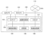
- FIG. 1 is a diagram schematically showing an overall configuration of an in-vehicle camera device according to the present embodiment. It is a functional block diagram which shows roughly the processing content in the object recognition process in a vehicle-mounted camera apparatus, and a blurring correction process. It is a figure which shows the flow of the object recognition process in a vehicle-mounted camera apparatus, and a blurring correction process. It is a flowchart which shows the image processing of the vehicle-mounted camera apparatus in this Embodiment. It is a figure which shows typically an example of the short time exposure image at the time of imaging the traffic sign which is an example of the recognition object in a vehicle-mounted camera apparatus.
- FIG. 1 is a diagram schematically showing an overall configuration of an in-vehicle camera device according to the present embodiment.
- an in-vehicle camera device 100 is schematically composed of a pair of cameras 101 and 102, a camera interface 103, an image processing unit 104, an arithmetic processing unit 105, a storage unit 108, a control processing unit 106, a CAN interface 107, a bus 109, and the like. It is configured.
- the camera interface 103, the image processing unit 104, the arithmetic processing unit 105, the storage unit 108, the control processing unit 106, and the CAN interface 107 are connected by a bus 109, and exchange various information with each other through the bus 109.
- CAN Controller Area Network
- the own vehicle a vehicle in which the in-vehicle camera device 100 is mounted
- Various information is exchanged with other control systems.
- the pair of cameras 101 and 102 (the left camera 101 and the right camera 102) is an imaging unit for capturing an image of a shooting target region and acquiring an image, and images the same direction so that the optical axes are parallel to each other.
- the left camera 101 and the right camera 102 are connected to the bus 109 via a camera interface 103 for transferring images taken by the left camera 101 and the right camera 102 and control signals to the left camera 101 and the right camera 102.
- the left camera 101 and the right camera 102 can adjust the shutter time (exposure time) based on a control signal input via the camera interface 103 and perform imaging to acquire images having different shutter times. It is configured.
- the image processing unit 104 corrects images obtained from the image sensors of the cameras 101 and 102, calculates parallax information using these images, and the like. As a correction process, the image processing unit 104 compares an image (first image) obtained from the image sensor of the camera 101 with an image (second image) obtained from the image sensor of the camera 102, and determines each image. Correction processing that corrects device-specific deviation caused by the image sensor (image processing such as correction to absorb inherent wrinkles of the image sensor), image correction processing such as noise interpolation processing, and blur correction parameters The calculation process (described later) is performed, and these images are stored in the storage unit 108. Further, the image processing unit 104 performs a parallax information calculation process based on a mutually corresponding portion between the first and second images, and stores the calculation result (parallax information) in the storage unit 108.
- the arithmetic processing unit 105 uses the image stored in the storage unit 108 and parallax information (distance information from the in-vehicle camera device 100 (or the own vehicle) with respect to each point (each object) on the image), and the environment around the vehicle Recognition processing (object recognition processing) of various objects necessary for perceiving the image.
- the various objects include, for example, people, cars, other obstacles, traffic lights, signs, car tail lamps, headlights, and the like.
- Some of these recognition results and intermediate calculation results are stored in the storage unit 108.
- the arithmetic processing unit 105 calculates the control policy of the host vehicle using the recognition results. A part of the vehicle control policy and the result of the object recognition processing obtained as a result of the calculation are transmitted to the CAN 110 through the CAN interface 107, and vehicle control (vehicle control processing) is performed using these pieces of information.
- the control processing unit 106 controls the overall operation of the in-vehicle camera device 100, and each processing unit of the in-vehicle camera device 100 does not cause an abnormal operation or when information is transmitted (during data transfer). It monitors whether or not an error has occurred, and is designed to prevent abnormal operation.
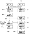
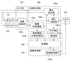
- FIG. 2 is a functional block diagram schematically showing the processing contents in the object recognition processing and blur correction processing in the in-vehicle camera device.
- FIG. 3 is a diagram showing a flow of object recognition processing and blur correction processing in the in-vehicle camera device.
- the images captured by the left camera 101 and the right camera 102 obtained through the image acquisition unit 103 a of the camera interface 103 are the image preprocessing unit 104 a of the image processing unit 104 and the parallax information calculation process.
- the stereo image processing 201, the three-dimensional object detection processing 202, and the left and right monocular image processing 301 are executed and stored in the storage unit 108.
- an image obtained from the image sensor of the camera 101 is compared with an image obtained from the image sensor of the camera 102 (second image).
- Deviation correction processing image processing such as correction to absorb the inherent wrinkles of the image sensor
- image correction processing such as noise interpolation processing for each image to correct the device-specific deviation caused by the image sensor I do.
- a parallax information calculation process is performed in which a parallax information calculation process is performed based on a mutually corresponding portion between the first and second images. Note that in the left and right monocular image processing 301, image processing such as deviation correction processing and noise interpolation processing is performed on the first image and the second image obtained by varying the exposure time between the camera 101 and the camera 102.
- a three-dimensional object is detected in a stereo image composed of a first image and a second image that are gradation images, a predetermined range including the three-dimensional object is cut out, and object recognition described later is performed.
- an image process for processing an edge image or the like is performed.
- the image that has been subjected to the three-dimensional object detection process 202 is read from the storage unit 108, and the object recognition process 203 is performed in the recognition processing unit 105 a of the arithmetic processing unit 105.
- an object in the image is identified using an object dictionary 108a (a data obtained by preliminarily creating an image of an object to be subjected to the object recognition process) stored in the storage unit 108.
- a process for determining what the object is (which recognition object is the object) is performed.
- the object recognition result 108b obtained by the object recognition process 203 is stored in the storage unit 108.
- Recognition objects that can become the object recognition result 108b include signs, people, vehicles, other three-dimensional objects, traffic lights, tail lamps, and the like.
- the object recognition result 108b is used by the arithmetic processing unit 105 to calculate the control policy of the host vehicle.
- the control policy of the host vehicle is calculated in consideration of the object recognition result 108b and the state (speed, rudder angle, etc.) of the host vehicle, is transmitted to the CAN 110 via the CAN interface 107, and is used for a vehicle control process or the like. It is done.
- a warning to the occupant by voice or warning light control of braking of the own vehicle, steering angle adjustment, or the like, or Performs avoidance control of the object.
- the correction determination unit 104c of the image processing unit 104 includes whether or not to execute blur correction parameter calculation processing (that is, blur correction parameter calculation processing, image blur correction processing using the blur correction parameter, and the like). Whether or not to start the blur correction process.
- blur correction parameter calculation processing that is, blur correction parameter calculation processing, image blur correction processing using the blur correction parameter, and the like.
- the surrounding environment (brightness) of the subject vehicle to be imaged based on images obtained by the cameras 101 and 102 or information from other devices obtained via the CAN interface 107.
- the blur correction parameter calculation process is determined to be executed when darker than a predetermined reference, and is determined not to be executed in other cases.
- the determination method in the correction determination unit 104c is not limited to the above, and may be determined as appropriate based on other information.
- the exposure setting unit 104d controls the exposure times of the cameras 101 and 102 and acquires images having different exposure times.
- the cameras 101 and 102 start imaging at the same time and change the timing of ending the imaging, whereby the first image (short-time exposure image) captured by one camera (for example, the camera 101) and the other camera ( For example, two images having different exposure times can be obtained by acquiring a second image (long-time exposure image) captured by a camera 102) and having an exposure time longer than that of the first image. Get an image.
- the exposure time (exposure time difference) set for each camera 101, 102 is initially adjusted in advance, and is adjusted (re-adjusted) appropriately based on a calculation result in an exposure time calculation process 304 described later. Set).
- the cameras 101 and 102 do not need to capture images with different exposure times. For example, an image captured with the exposure times of the cameras 101 and 102 set to be the same as an image captured with different exposure times set. Can be obtained alternately.
- the correction determination unit 104c determines that the blur correction parameter calculation process is to be performed, the blur estimation calculation process 302 and the exposure time calculation process 304 in the blur correction parameter acquisition unit 104e of the image processing unit 104, and an arithmetic processing unit A blur correction calculation process 303 in the recognition processing unit 105a of 105 is executed.
- the blur estimation calculation process 302 a plurality of the same detected objects (for example, signs) are detected using the calculation result of the parallax information calculation process in the stereo image process 201 and the detection result of the three-dimensional object in the three-dimensional object detection process 202.
- Blur estimation is performed from images captured at different exposure times, and a blur amount (blur correction parameter) is calculated.
- a vague calculation such as the amount of blur of the entire image, but also a more accurate estimation of the amount of blur according to the distance to the object and the movement of the host vehicle (vehicle speed) is possible.
- the blur correction calculation process 303 based on the blur amount calculated in the blur estimation calculation process 302, a process of correcting the blur of the image referred to in the object recognition process 203 is executed.
- the object recognition process 203 the object recognition process is performed based on a clearer image that has been subjected to the blur correction calculation process 303, so that the detection target in the image can be recognized with higher accuracy.
- the exposure time calculation process 304 a more suitable exposure time in each of the cameras 101 and 102 based on the calculation result in the blur correction calculation process 303 (such as the clarity of the image after the blur correction calculation process 303 compensated for blur). The difference in exposure time) is calculated.
- the exposure time calculation result (exposure time calculation result 108c) in the exposure time calculation process 304 is sent to the exposure setting unit 104d, and the exposure time of the cameras 101 and 102 is adjusted.
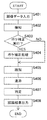
- FIG. 4 is a flowchart showing image processing of the in-vehicle camera device according to the present embodiment.
- the in-vehicle camera apparatus 100 receives image data of images obtained by the cameras 101 and 102 (step S401), and detects a three-dimensional object (for example, a sign) in the image (step S402). Next, whether or not it is necessary to analyze the image at the position where the three-dimensional object is detected and perform blur correction processing (such as blur correction parameter calculation processing or blur correction processing of the image using the blur correction parameter) (Step S403), if the determination result is YES, blur correction processing is executed (step S404), and the process proceeds to identification processing (step S405). If the determination result in step S403 is NO, the process directly proceeds to the identification process (step S405).
- blur correction processing such as blur correction parameter calculation processing or blur correction processing of the image using the blur correction parameter
- step S405 what is the object in the image (which identification target object) is identified (step S405), and the identified object is displayed on the image so as not to be interrupted in the time-series image.
- the identification is repeated while tracking the transition position (step S406), and based on the identification result performed over a plurality of frames, the identification object is finally determined (step S407). ),
- the determination result (identification result) is output as the recognition result (step S408), and the process ends.
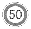
- 5 to 7 are diagrams schematically showing an example of an image when a traffic sign, which is an example of a recognition target in the in-vehicle camera device, is imaged.
- the point spread function representing the process (degradation process) is h (x, y)
- the function representing the original image is f (x, y)
- the function representing the blurred image is g (x, y).
- the blurred image is expressed by the following (Equation 1) using convolution (superposition) of the original image and the point spread function.
- the images captured by the pair of cameras 101 and 102 of the in-vehicle camera device 100 can be considered to be blurred images in which the original image has deteriorated
- the images are captured by one camera (for example, the camera 101).
- the first image short-time exposure image: equivalent to FIG. 5
- the second image captured by the other camera (for example, camera 102) with an exposure time longer than that of the first image.
- the following (Equation 2) and (Equation 3) also hold in the image (long exposure image: equivalent to FIG. 6).
- gs (x, y) is the first image (short-time exposure image)
- fs (x, y) is the image corresponding to the original image of the first image
- hs (x, y) y) is a point spread function representing the degradation process of the first image.
- gl (x, y) is a second image (long exposure image)
- fl (x, y) is an image corresponding to the original image of the second image
- hl (x, y) ) Is a point spread function representing the degradation process of the second image.
- the first image gs (x, y) and the second image gl (x, y) are captured at the same timing and image acquisition is performed.
- these images are acquired in one frame. Since the first image is captured with a short exposure time (compared to the second image), the image becomes dark and recognition of the recognition target becomes difficult, but blur due to movement is small. In other words, if the exposure time is sufficiently short, the darkness of the image can be ignored when considering only the degree of blur, so the first image gs (x, y) is changed to the second image gl (x , Y) can be treated as the original image fl (x, y). Therefore, by substituting gs (x, y) for fl (x, y) in the above (Expression 3), the following (Expression 4) is obtained.
- Equation 4 gl (x, y) and gs (x, y) are known, so that hl (x, y), which is a point spread function representing the degradation process of the second image, is obtained. Can do. Obtaining this function hl (x, y) corresponds to calculating a blur amount (blur correction parameter) by the image processing unit 104.
- the second image is captured with a long exposure time (compared to the first image), the second image is an image having sufficient brightness but a large degree of blur. Therefore, the second image is an image that can detect the object but is not suitable for identifying the object as it is.
- hl (x, y) which is a point spread function representing the deterioration process, is obtained by the above (Equation 4), and therefore gl (x, y) in the above (Equation 3).
- hl (x, y) become known, and the original image gl (x, y) of the second image can be obtained.
- an image having sufficient brightness and no blur that is, an image corresponding to the original image can be estimated (in other words, the original image can be restored in a pseudo manner).
- obtaining the original image gl (x, y) from the known gl (x, y) and hl (x, y) using the above (Equation 3) uses the blur correction parameter in the arithmetic processing unit 105. This corresponds to executing image correction processing.
- the point spread function hl (x, y) related to the degradation process is estimated from the second image (long-time exposure image), and obtained.
- An image corresponding to the original image fl (x, y) can be obtained by performing inverse convolution on the second image gl (x, y) using the obtained point spread function (blur correction parameter). It becomes possible.
- blur correction processing (blur amount calculation and blur correction of an image using the blur amount) is performed not according to the entire image but according to the position and distance of the detected object, so that more accurate estimation can be performed. It becomes possible. That is, for example, by correcting the function hl (x, y) obtained by the calculation processing in the image processing unit 104 based on the vehicle speed and the amount of calculation blur estimated from the target object, Since the function hl (x, y) with high accuracy can be obtained, the original image fl (x, y) can be estimated with higher accuracy using the function hl (x, y).
- an in-vehicle camera device having a pair of cameras can simultaneously measure visual information based on an image and distance information to an object, so various objects (people) around a car , Cars, solid objects, white lines / road surfaces, signs, etc.), and is a device that is expected to contribute to improvements in driving safety and driving support accuracy.
- Examples of recognition targets based on images from in-vehicle camera devices include traffic signs (road signs), and driving support such as acceleration / deceleration of self-driving cars that link the recognition results of traffic signs with map information has been studied. ing.
- evaluation items related to SAS are also established in the EuroNCAP (European New Car Assessment) (European New Car Assessment Program (2016-2020 Update)), which is an evaluation index for advanced driver assistance systems. The importance of traffic sign recognition is increasing.
- Such sign recognition technology requires reading of a fine pattern of signs, regardless of the daylight or night light requirements, and therefore blurs the sign part of the image obtained by the in-vehicle camera device. Need to be corrected.
- the exposure time is set based on the vehicle behavior against the blurring of the object caused by the driver's driving operation (brake, accelerator, etc.) and the long exposure time, and the optical flow calculation result
- the image blur is corrected based on the above. For this reason, for example, when driving on rough roads with many irregularities such as cobblestones, vertical fluctuations that are not directly related to the driving operation of the driver occur in the in-vehicle camera in a short time, and based on the calculation result of the optical flow Therefore, it has been difficult to cope with the conventional technique for correcting image blur.
- the exposure times of the pair of imaging units are individually set, and the first image captured by one imaging unit of the pair of imaging units and the pair of imaging units Of the second image captured by the pair of image capturing units, the second image captured by the other image capturing unit and captured by the exposure time longer than that of the first image. Since the blur is corrected, the image from the camera can be corrected with higher accuracy, and the recognition accuracy of the detection target in the image can be improved.
- this invention is not limited to each above-mentioned embodiment, Various modifications are included.
- the above-described embodiment has been described in detail for easy understanding of the present invention, and is not necessarily limited to one having all the configurations described.
- Each of the above-described configurations, functions, and the like may be realized by software by interpreting and executing a program that realizes each function by the processor.
- DESCRIPTION OF SYMBOLS 100 Car-mounted camera apparatus 101 Left camera 102 Right camera 103 Camera interface 103a Image acquisition part 104 Image processing part 104a Image pre-processing part 104b Disparity information calculation processing part 104c Correction judgment part 104d Exposure setting part 104e Blur correction parameter acquisition part 105 Operation processing part 105a recognition processing unit 106 control processing unit 107 CAN interface 108 storage unit 108a object dictionary 108b object recognition result 108c exposure time calculation result 109 bus 110 CAN (Controller Area Network) 201 Stereo image processing 202 Three-dimensional object detection processing 203 Object recognition processing 301 Left and right monocular image processing 302 Blur estimation calculation processing 303 Blur correction calculation processing 304 Exposure time calculation processing
Landscapes
- Engineering & Computer Science (AREA)
- Multimedia (AREA)
- Signal Processing (AREA)
- Studio Devices (AREA)
- Image Processing (AREA)
Abstract
本発明は、カメラからの画像をより精度良く補正することができる画像補正装置および画像補正方法を提供する。本発明は、同じ対象物を同時に撮像可能な一対のカメラ101,102と、一対のカメラ101,102のうち一方の撮像部で撮像された第1の画像と、一対の撮像部カメラ101,102のうち他方の撮像部で撮像された画像であって第1の画像よりも露光時間を長くして撮像された第2の画像とに基づいて、一対の撮像部で撮像された第2の画像のボケを補正する画像処理部104及び演算処理部105とを備える。
Description
本発明は、カメラにより撮像された画像の補正を行う画像補正装置および画像補正方法に関する。
安全運転や自動運転に向けた技術の社会的認知度の向上に伴って車載カメラ装置による画像に基づいた各種物体認識や距離測定への要求内容は高度化しており、例えば、夜間やトンネル内のように外光の少ない状態において、シャッタ時間(露光時間)を長く設定することにより画像の撮像に十分な露光を確保しようとした場合に、自車の走行による移動等により画像に生じるボケを補正する技術の向上などが望まれている。
このような画像の補正に関する技術として、例えば、特許文献1(特開2005-318568号公報)には、車両の前方を連続して撮像するカメラと、前記カメラにより連続して撮像された各画像におけるオブジェクトの位置に基づいて、各オブジェクトの画像内における移動ベクトルを算出する移動ベクトル算出手段と、前記移動ベクトル算出手段により算出された前記移動ベクトルを用いて、前記カメラにより撮像された前記画像のぶれを補正するぶれ補正手段と、を備えた画像補正装置が開示されている。
車載カメラ装置の画像に基づく認識対象には、例えば、交通標識(道路標識)などがあり、交通標識の認識結果と地図情報とを連携した自動運転車の加速・減速などの運転支援が研究されている。また、先進運転支援システムの評価指標であるEuroNCAP(European New Car Assessment Program:ヨーロッパ新車アセスメントプログラム(2016年~2020年アップデート))においても、SAS(Speed Assistance Systems:速度支援システム)に関する評価項目が設けられており、交通標識の認識について重要度が増している。
このような標識認識に関する技術では、昼・夜などの外光要件を問わず、かつ、標識の細かな模様の読み取りを必要とするため、車載カメラ装置で得られた画像の特に標識部分のボケを補正する必要がある。
しかしながら、上記従来技術においては、ドライバーの運転操作(ブレーキ、アクセルなど)と長い露光時間に起因して生じる対象物のブレに対して、車両挙動に基づいて露光時間を設定し、オプティカルフローの算出結果に基づいて画像のぶれを補正している。このため、例えば石畳のような凹凸の多い悪路上を走行した場合には、ドライバーの運転操作に直接関係しない上下変動が短時間のうちに車載カメラに生じてしまい、オプティカルフローの算出結果に基づいて画像のぶれを補正する従来技術では対応することが難しかった。
本発明は上記に鑑みてなされたものであり、カメラからの画像をより精度良く補正することができる画像補正装置および画像補正方法を提供することを目的とする。
上記目的を達成するために、本発明は、同じ対象物を同時に撮像可能な一対の撮像部と、前記一対の撮像部のうち一方の撮像部で撮像された第1の画像と、前記一対の撮像部のうち他方の撮像部で撮像された画像であって前記第1の画像よりも露光時間を長くして撮像された第2の画像とに基づいて、前記一対の撮像部で撮像された第2の画像のボケを補正するボケ補正部とを備えたものとする。
本発明によれば、カメラからの画像をより精度良く補正することができ、画像中における検知対象物の認識精度を向上することができる。
以下、本発明の実施の形態を図面を参照しつつ説明する。
図1は、本実施の形態に係る車載カメラ装置の全体構成を概略的に示す図である。
図1において、車載カメラ装置100は、一対のカメラ101,102、カメラインタフェース103、画像処理部104、演算処理部105、記憶部108、制御処理部106、CANインタフェース107、およびバス109などにより概略構成されている。カメラインタフェース103、画像処理部104、演算処理部105、記憶部108、制御処理部106、及びCANインタフェース107は、バス109により接続されており、このバス109を介して互いに種々の情報の授受を行うことができるほか、CANインタフェース107を介して外部の車載ネットワークであるCAN(Controller Area Network)110に接続されており、CAN110を介して自車両(車載カメラ装置100が搭載されている車両)の他の制御システムとの間で種々の情報の授受を行う。
一対のカメラ101,102(左カメラ101、右カメラ102)は、撮影対象領域を撮像して画像を取得するための撮像部であり、光軸が並行になるように、かつ、同じ方向を撮像するように車載カメラ装置100に左右に配置されている。左カメラ101および右カメラ102は、左カメラ101および右カメラ102で撮像した画像や、左カメラ101および右カメラ102への制御信号の授受を行うためのカメラインタフェース103を介してバス109に接続されている。左カメラ101および右カメラ102は、カメラインタフェース103を介して入力される制御信号に基づいてシャッタ時間(露光時間)を調整して撮像を行い、それぞれシャッタ時間の異なる画像を取得することができるように構成されている。
画像処理部104は、カメラ101,102の撮像素子から得られた画像の補正や、それらの画像を用いた視差情報の算出処理などを行う。画像処理部104は補正処理として、カメラ101の撮像素子から得られる画像(第1の画像)と、カメラ102の撮像素子から得られる画像(第2の画像)とを比較して、それぞれの画像に対して撮像素子に起因するデバイス固有の偏差を補正する補正処理(撮像素子が持つ固有の癖を吸収するための補正などの画像処理)や、ノイズ補間処理などの画像補正処理、ボケ補正パラメータ(後述)の計算処理などを行い、これらの画像を記憶部108に記憶する。また、画像処理部104は、第1及び第2の画像の間の相互に対応する箇所に基づいて視差情報の計算処理を行い、その計算結果(視差情報)を記憶部108に記憶する。
演算処理部105は、記憶部108に記憶された画像および視差情報(画像上の各点(各対象物)に対する車載カメラ装置100(或いは自車両)からの距離情報)を使い、車両周辺の環境を知覚するために必要な、各種物体の認識処理(物体認識処理)を行う。ここで、各種物体とは、例えば、人、車、その他の障害物、信号機、標識、車のテールランプやヘッドライトなどである。これら認識結果や中間的な計算結果の一部は記憶部108に記憶される。また、演算処理部105は、撮像した画像に対して行った物体認識処理後に、それらの認識結果を用いて自車両の制御方針を計算する。計算の結果として得られた車両の制御方針や物体認識処理の結果の一部はCANインタフェース107を通してCAN110に送信され、これらの情報を用いて車両の制御(車両制御処理)が行われる。
制御処理部106は、車載カメラ装置100の全体の動作を制御するものであり、車載カメラ装置100の各処理部が異常動作を起こしていないか、或いは、情報の送信時(データ転送時)にエラーが発生していないかどうかなどを監視しており、異常動作を防ぐ仕掛けとなっている。
図2は、車載カメラ装置における物体認識処理やボケ補正処理における処理内容を概略的に示す機能ブロック図である。また、図3は、車載カメラ装置における物体認識処理やボケ補正処理の流れを示す図である。
図2及び図3において、カメラインタフェース103の画像取得部103aを介して得られた左カメラ101及び右カメラ102で撮像された画像は、画像処理部104の画像前処理部104a及び視差情報計算処理部104bに送られてステレオ画像処理201や立体物検知処理202、左右単眼画像処理301が実行され、記憶部108に記憶される。
ステレオ画像処理201及び左右単眼画像処理301では、カメラ101の撮像素子から得られる画像(第1の画像)と、カメラ102の撮像素子から得られる画像(第2の画像)とを比較して、それぞれの画像に対して撮像素子に起因するデバイス固有の偏差を補正する偏差補正処理(撮像素子が持つ固有の癖を吸収するための補正などの画像処理)や、ノイズ補間処理などの画像補正処理を行う。また、ステレオ画像処理201では、さらに、第1及び第2の画像の間の相互に対応する箇所に基づいて視差情報の計算処理を行う視差情報計算処理を行う。なお、左右単眼画像処理301では、カメラ101とカメラ102で露光時間を異ならせて得られる第1の画像と第2の画像について偏差補正処理やノイズ補間処理などの画像処理を行う。
また、立体物検知処理202では、階調画像である第1の画像と第2の画像で構成されるステレオ画像において立体物を検知し、立体物を含む所定の範囲を切出し、後述する物体認識処理203用にエッジ画像などに加工する画像処理を行う。
立体物検知処理202を実施された画像は、記憶部108から読み出され、演算処理部105の認識処理部105aにおいて、物体認識処理203を実施される。物体認識処理203では、記憶部108に予め記憶された物体辞書108a(物体認識処理の対象となる物体の画像等を予めデータ化したもの)を用いて画像中の物体を識別し、その物体が何であるか(何れの認識対象物であるか)を判定する処理を行う。物体認識処理203による物体認識結果108bは、記憶部108に記憶される。物体認識結果108bとなりうる認識対象物としては、標識や,人、車両,その他の立体物、信号機、テールランプなどがある。
物体認識結果108bは、演算処理部105において自車両の制御方針の計算に用いられる。自車両の制御方針は、物体認識結果108bと、自車両の状態(速度、舵角など)とを勘案して計算され、CANインタフェース107を介してCAN110に送信されて、車両制御処理などに用いられる。車両制御処理では、演算処理部105で計算された制御方針に基づき、例えば、音声や警告灯などによる乗員への警告の発報や、自車両のブレーキング、舵角調整などの制御、或いは、対象物の回避制御を行う。
画像処理部104の補正判断部104cは、ボケ補正パラメータの計算処理を実行するかどうか(すなわち、ボケ補正パラメータの計算処理や、そのボケ補正パラメータを用いた画像のボケの補正処理などにより構成されるボケ補正処理を開始するかどうか)を判断する。補正判断部104cでは、例えば、カメラ101,102で得られた画像、或いは、CANインタフェース107を介して得られる他のデバイスからの情報に基づいて撮像対象となる自車の周辺環境(明るさ)に係る情報を取得し、予め定めた基準よりも暗い場合にボケ補正パラメータの計算処理を実行するよう判断し、その他の場合は実行しないように判断する。また、CANインタフェース107を介して得られる自車の走行速度に基づいて、予め定めた基準よりも速い場合にボケ補正パラメータの計算処理を実行するよう判断し、その他の場合は実行しないように判断するよう構成しても良い。なお、補正判断部104cにおける判断方法は上記に限られず、他の情報に基づいて適宜判断するように構成しても良い。
補正判断部104cでボケ補正パラメータの計算処理の実行が判断されると、露光設定部104dは、カメラ101,102の露光時間を制御し、露光時間の異なる画像を取得する。カメラ101,102では、同時に撮像を開始し、撮像終了のタイミングを異ならせることにより、一方のカメラ(例えばカメラ101)で撮像された第1の画像(短時間露光画像)と、他方のカメラ(例えばカメラ102)で撮像された画像であって第1の画像よりも露光時間を長くして撮像された第2の画像(長時間露光画像)とを取得することにより、露光時間の異なる2つの画像を取得する。なお、各カメラ101,102に設定する露光時間(露光時間の差)は、初めは予め定めておいた初期値を用い、後述する露光時間計算処理304での計算結果に基づいて適宜調整(再設定)する。また、カメラ101,102は露光時間が異なる状態で撮像する必要はなく、例えば、カメラ101,102の露光時間を同じに設定して撮像した画像と、露光時間を異なる設定にして撮像した画像とを交互に取得するように構成することができる。
また、補正判断部104cでボケ補正パラメータの計算処理の実行が判断されると、画像処理部104のボケ補正パラメータ取得部104eでのボケ推定計算処理302及び露光時間計算処理304と、演算処理部105の認識処理部105aでのボケ補正計算処理303とが実行される。
ボケ推定計算処理302では、ステレオ画像処理201での視差情報計算処理の計算結果や、立体物検知処理202での立体物の検知結果を用いて、同一の検知物体(例えば標識など)に対する複数の異なる露光時間で撮像された画像からボケ推定を行い、ボケ量(ボケ補正パラメータ)を計算する。これにより、画像全体のボケ量といった漠然とした計算だけでなく、対象物との距離や自車の移動(自車速度)に応じたボケ量のより正確な推定が可能となる。
ボケ補正計算処理303では、ボケ推定計算処理302で計算されたボケ量に基づいて、物体認識処理203で参照する画像のボケを補正する処理を実行する。物体認識処理203では、ボケ補正計算処理303を実行された、より鮮明な画像に基づいて物体認識処理を行うので、より高い精度で画像中の検知対象物を認識することが可能となる。
露光時間計算処理304では、ボケ補正計算処理303での計算結果(ボケを補したボケ補正計算処理303後の画像の明確さなど)に基づいて、各カメラ101,102におけるより適した露光時間(露光時間の差)が計算される。露光時間計算処理304における露光時間の計算結果(露光時間計算結果108c)は、露光設定部104dに送られ、カメラ101,102の露光時間の調整が行われる。
図4は、本実施の形態における車載カメラ装置の画像処理を示すフローチャートである。
図4において、車載カメラ装置100には、カメラ101,102で得られた画像の画像データが入力され(ステップS401)、画像中における立体物(例えば標識)が検知される(ステップS402)。次に、立体物を検知した位置の画像を解析して、ボケ補正処理(ボケ補正パラメータの計算処理や、ボケ補正パラメータを用いた画像のボケの補正処理など)を実行する必要があるかどうかを判定し(ステップS403)、判定結果がYESの場合には、ボケ補正処理を実行し(ステップS404)、識別の処理(ステップS405)に進む。また、ステップS403での判定結果がNOの場合には、そのまま識別の処理(ステップS405)に進む。識別の処理では、画像中の物体が何であるのか(何れの識別対象物であるのか)を識別し(ステップS405)、識別された物体を時系列で得られた画像において途切れないよう画像上の遷移位置を追跡しつつ識別を繰り返し(ステップS406)、複数フレームに渡って行われた識別結果に基づいて、識別された物体が何れの識別対象物であるのかを最終的に判定し(ステップS407)、判定結果(識別結果)を認識結果として出力し(ステップS408)、処理を終了する。
ここで、本実施の形態における画像のボケを補正する処理の原理について説明する。
図5~図7は、車載カメラ装置における認識対象の一例である交通標識を撮像した場合の画像の一例を模式的に示す図である。
例えば、図7に示すようなボケの無い合焦点の画像(原画像)と、図6のように原画像に対してボケのある画像(ボケ画像)とが有る場合、原画像からボケ画像になる過程(劣化過程)を表す点拡がり関数(PSF:Point Spread Function)をh(x,y)、原画像を表す関数をf(x,y)、ボケ画像を表す関数をg(x,y)とすると、ボケ画像は、原画像と点拡がり関数とのコンボリューション(重畳)を用いて以下の(式1)で表される。

ここで、車載カメラ装置100の一対のカメラ101,102において撮像される画像は、それぞれ、原画像が劣化したボケ画像であると考えることができるので、一方のカメラ(例えばカメラ101)で撮像された第1の画像(短時間露光画像:図5相当)と、他方のカメラ(例えばカメラ102)で撮像された画像であって第1の画像よりも露光時間を長くして撮像された第2の画像(長時間露光画像:図6相当)とにおいても、以下の(式2)及び(式3)が成り立つ。


ここで、(式2)において、gs(x,y)は第1の画像(短時間露光画像)、fs(x,y)は第1の画像の原画像に相当する画像、hs(x,y)は第1の画像の劣化過程を表す点拡がり関数である。また、(式3)において、gl(x,y)は第2の画像(長時間露光画像)、fl(x,y)は第2の画像の原画像に相当する画像、hl(x,y)は第2の画像の劣化過程を表す点拡がり関数である。
第1の画像gs(x,y)と第2の画像gl(x,y)は、同じタイミングで撮像開始されて画像取得される。車載カメラ装置100のステレオカメラ(一対のカメラ101,102)においては、これらの画像を1フレームで取得する。第1の画像は(第2の画像と比較して)短い露光時間で撮像するため画像が暗くなり、認識対象物の認識は難しくなるが、動きによるボケは小さい。つまり、露光時間が十分に短い場合は、ボケの程度のみを考える場合には画像の暗さを無視することができるので、第1の画像gs(x,y)を第2の画像gl(x,y)における原画像fl(x,y)として扱うことができる。したがって、gs(x,y)を上記(式3)のfl(x,y)に代入することにより下記(式4)が得られる。

上記(式4)においては、gl(x,y)及びgs(x,y)が既知であるため、第2の画像の劣化過程を表す点拡がり関数であるhl(x,y)を求めることができる。この関数hl(x,y)を求めることは、画像処理部104でボケ量(ボケ補正パラメータ)を計算することに相当する。
一方、第2の画像は(第1の画像と比較して)長い露光時間で撮像するため、十分な明るさがあるがボケの程度が大きい画像となる。したがって、第2の画像は、そのままでは、物体の検知はできるが物体の識別には適さない画像ということになる。ここで、第2の画像については、上記(式4)により劣化過程を表す点拡がり関数であるhl(x,y)が得られているため、上記(式3)においてgl(x,y)及びhl(x,y)が既知となり、第2の画像の原画像gl(x,y)を求めることができる。つまり、明るさが十分にあり、かつ、ボケの無い画像、すなわち、原画像相当の画像を推定する(言い換えると、擬似的に原画像を復元する)ことができる。ここで、既知のgl(x,y)及びhl(x,y)から上記(式3)を用いて原画像gl(x,y)を得ることは、演算処理部105においてボケ補正パラメータを用いて画像の補正処理を実行することに相当する。
このように、第1の画像(短時間露光画像)を原画像と仮定して第2の画像(長時間露光画像)から劣化過程に係る点拡がり関数hl(x,y)を推定し、得られた点拡がり関数(ボケ補正パラメータ)を使い、第2の画像gl(x,y)に対して逆コンボリューションを掛けることで、原画像fl(x,y)に相当する画像を得ることが可能となる。
なお、ボケ補正処理(ボケ量の計算やボケ量を用いた画像のボケの補正処理)を画像全体では無く、検知した対象物の位置や距離に応じて行う事で、さらに高精度な推定が可能となる。すなわち、例えば、自車速度や対象物から予測される計算上のボケ量に基づいて、画像処理部104での計算処理により得られた関数hl(x,y)の補正を行うことにより、さらに精度の良い関数hl(x,y)を得ることができるので、この関数hl(x,y)を用いてさらに精度良く原画像fl(x,y)を推定することができる。
以上のように構成した本実施の形態の効果を説明する。
例えば一対のカメラを有する車載カメラ装置(ステレオカメラ装置)は、画像による視覚的な情報と、対象物への距離情報とを同時に計測することが可能なため、自動車周辺の様々な対象物(人、車、立体物、白線・路面、標識など)を詳細に把握できるという特徴を有しており、運転時の安全性の向上や運転支援の精度向上への寄与が期待されるデバイスである。
車載カメラ装置の画像に基づく認識対象には、例えば、交通標識(道路標識)などがあり、交通標識の認識結果と地図情報とを連携した自動運転車の加速・減速などの運転支援が研究されている。また、先進運転支援システムの評価指標であるEuroNCAP(European New Car Assessment Program:ヨーロッパ新車アセスメントプログラム(2016年~2020年アップデート))においても、SAS(Speed Assistance Systems:速度支援システム)に関する評価項目が設けられており、交通標識の認識について重要度が増している。
このような標識認識に関する技術では、昼・夜などの外光要件を問わず、かつ、標識の細かな模様の読み取りを必要とするため、車載カメラ装置で得られた画像の特に標識部分のボケを補正する必要がある。
しかしながら、従来技術においては、ドライバーの運転操作(ブレーキ、アクセルなど)と長い露光時間に起因して生じる対象物のブレに対して、車両挙動に基づいて露光時間を設定し、オプティカルフローの算出結果に基づいて画像のぶれを補正している。このため、例えば石畳のような凹凸の多い悪路上を走行した場合には、ドライバーの運転操作に直接関係しない上下変動が短時間のうちに車載カメラに生じてしまい、オプティカルフローの算出結果に基づいて画像のぶれを補正する従来技術では対応することが難しかった。
これに対して本実施の形態においては、一対の撮像部の露光時間をそれぞれ個別に設定し、一対の撮像部のうち一方の撮像部で撮像された第1の画像と、一対の撮像部のうち他方の撮像部で撮像された画像であって第1の画像よりも露光時間を長くして撮像された第2の画像とに基づいて、一対の撮像部で撮像された第2の画像のボケを補正するように構成したので、カメラからの画像をより精度良く補正することができ、画像中における検知対象物の認識精度を向上することができる。
なお、本発明は上記した各実施の形態に限定されるものではなく、様々な変形例が含まれる。例えば、上記した実施の形態は本願発明を分かりやすく説明するために詳細に説明したものであり、必ずしも説明した全ての構成を備えるものに限定されるものではない。
また、上記の各構成、機能等は、それらの一部又は全部を、例えば集積回路で設計する等により実現してもよい。また、上記の各構成、機能等は、プロセッサがそれぞれの機能を実現するプログラムを解釈し、実行することによりソフトウェアで実現してもよい。
また、上記の各構成、機能等は、それらの一部又は全部を、例えば集積回路で設計する等により実現してもよい。また、上記の各構成、機能等は、プロセッサがそれぞれの機能を実現するプログラムを解釈し、実行することによりソフトウェアで実現してもよい。
100 車載カメラ装置
101 左カメラ
102 右カメラ
103 カメラインタフェース
103a 画像取得部
104 画像処理部
104a 画像前処理部
104b 視差情報計算処理部
104c 補正判断部
104d 露光設定部
104e ボケ補正パラメータ取得部
105 演算処理部
105a 認識処理部
106 制御処理部
107 CANインタフェース
108 記憶部
108a 物体辞書
108b 物体認識結果
108c 露光時間計算結果
109 バス
110 CAN(Controller Area Network)
201 ステレオ画像処理
202 立体物検知処理
203 物体認識処理
301 左右単眼画像処理
302 ボケ推定計算処理
303 ボケ補正計算処理
304 露光時間計算処理
Claims (5)
- 同じ対象物を同時に撮像可能な一対の撮像部と、
前記一対の撮像部のうち一方の撮像部で撮像された第1の画像と、前記一対の撮像部のうち他方の撮像部で撮像された画像であって前記第1の画像よりも露光時間を長くして撮像された第2の画像とに基づいて、前記一対の撮像部で撮像された第2の画像のボケを補正するボケ補正部とを備えたことを特徴とする画像補正装置。 - 請求項1記載の画像補正装置において、
前記一対の撮像部により撮像された第1及び第2の画像中から予め定めた検知対象を検知する検知部を備え、
前記ボケ補正部は、前記検知対象と前記一対の撮像部との相対的な移動に起因するボケを補正することを特徴とする画像補正装置。 - 請求項1記載の画像補正装置において、
前記一対の撮像部により撮像された画像中から予め定めた検知対象を検知する検知部を備え、
前記ボケ補正部は、前記一対の撮像部により同一のタイミングで撮像された前記画像中の検知対象のボケを補正することを特徴とする画像補正装置。 - 請求項1記載の画像補正装置において、
前記ボケ補正部は、前記第1及び第2の画像に基づいてボケ補正パラメータを生成し、前記ボケ補正パラメータを用いて前記第2の画像のボケを補正することを特徴とする画像補正装置。 - 同じ対象物を同時に撮像可能な一対の撮像部のうち一方の撮像部で第1の画像を撮像し、前記一対の撮像部のうち他方の撮像部で撮像された画像であって前記第1の画像よりも露光時間を長くして第2の画像を撮像する撮像工程と、
前記撮像工程で撮像された第1及び第2の画像に基づいて、前記一対の撮像部で撮像された第2の画像のボケを補正するボケ補正工程とを有することを特徴とする画像補正方法。
Priority Applications (1)
| Application Number | Priority Date | Filing Date | Title |
|---|---|---|---|
| JP2018553764A JP6808753B2 (ja) | 2016-11-30 | 2017-11-16 | 画像補正装置および画像補正方法 |
Applications Claiming Priority (2)
| Application Number | Priority Date | Filing Date | Title |
|---|---|---|---|
| JP2016-233495 | 2016-11-30 | ||
| JP2016233495 | 2016-11-30 |
Publications (1)
| Publication Number | Publication Date |
|---|---|
| WO2018101055A1 true WO2018101055A1 (ja) | 2018-06-07 |
Family
ID=62241297
Family Applications (1)
| Application Number | Title | Priority Date | Filing Date |
|---|---|---|---|
| PCT/JP2017/041206 Ceased WO2018101055A1 (ja) | 2016-11-30 | 2017-11-16 | 画像補正装置および画像補正方法 |
Country Status (2)
| Country | Link |
|---|---|
| JP (1) | JP6808753B2 (ja) |
| WO (1) | WO2018101055A1 (ja) |
Cited By (3)
| Publication number | Priority date | Publication date | Assignee | Title |
|---|---|---|---|---|
| JP2022038576A (ja) * | 2020-08-27 | 2022-03-10 | 株式会社ニコン | 撮像システム及び撮像方法 |
| WO2023175708A1 (ja) * | 2022-03-15 | 2023-09-21 | 日立Astemo株式会社 | 外界認識装置、および、外界認識方法 |
| WO2025000479A1 (zh) * | 2023-06-30 | 2025-01-02 | 北京小米移动软件有限公司 | 摄影系统,具备摄影系统的拍摄装置,以及具备摄影系统的智能手机 |
Citations (2)
| Publication number | Priority date | Publication date | Assignee | Title |
|---|---|---|---|---|
| JP2004312583A (ja) * | 2003-04-10 | 2004-11-04 | Minolta Co Ltd | 撮像装置 |
| JP2008123396A (ja) * | 2006-11-15 | 2008-05-29 | Sanyo Electric Co Ltd | 画像復元装置及び方法並びに撮像装置 |
-
2017
- 2017-11-16 JP JP2018553764A patent/JP6808753B2/ja active Active
- 2017-11-16 WO PCT/JP2017/041206 patent/WO2018101055A1/ja not_active Ceased
Patent Citations (2)
| Publication number | Priority date | Publication date | Assignee | Title |
|---|---|---|---|---|
| JP2004312583A (ja) * | 2003-04-10 | 2004-11-04 | Minolta Co Ltd | 撮像装置 |
| JP2008123396A (ja) * | 2006-11-15 | 2008-05-29 | Sanyo Electric Co Ltd | 画像復元装置及び方法並びに撮像装置 |
Non-Patent Citations (1)
| Title |
|---|
| HATANAKA, HARUO ET AL.: "An Image Stabilization Technology for Digital Still Camera Based on Blind Deconvolution", IEICE TRANSACTIONS ON INFORMATION AND SYSTEMS , THE INSTITUTE OF ELECTRONICS, INFORMATION AND COMMUNICATION ENGINEERS, vol. E94-D, no. 5, 11 May 2011 (2011-05-11), pages 1082 - 1089, XP031467015 * |
Cited By (9)
| Publication number | Priority date | Publication date | Assignee | Title |
|---|---|---|---|---|
| JP2022038576A (ja) * | 2020-08-27 | 2022-03-10 | 株式会社ニコン | 撮像システム及び撮像方法 |
| JP7604809B2 (ja) | 2020-08-27 | 2024-12-24 | 株式会社ニコン | 撮像システム及び撮像方法 |
| WO2023175708A1 (ja) * | 2022-03-15 | 2023-09-21 | 日立Astemo株式会社 | 外界認識装置、および、外界認識方法 |
| JPWO2023175708A1 (ja) * | 2022-03-15 | 2023-09-21 | ||
| JP7769779B2 (ja) | 2022-03-15 | 2025-11-13 | Astemo株式会社 | 外界認識装置、および、外界認識方法 |
| WO2025000479A1 (zh) * | 2023-06-30 | 2025-01-02 | 北京小米移动软件有限公司 | 摄影系统,具备摄影系统的拍摄装置,以及具备摄影系统的智能手机 |
| CN119547451A (zh) * | 2023-06-30 | 2025-02-28 | 北京小米移动软件有限公司 | 摄影系统,具备摄影系统的拍摄装置,以及具备摄影系统的智能手机 |
| JP2025524250A (ja) * | 2023-06-30 | 2025-07-28 | 北京小米移動軟件有限公司 | 撮影システム、撮影システムを備えた撮像装置、及び撮影システムを備えたスマートフォン |
| JP7869221B2 (ja) | 2023-06-30 | 2026-06-02 | 北京小米移動軟件有限公司 | 撮影システム、撮影システムを備えた撮像装置、及び撮影システムを備えたスマートフォン |
Also Published As
| Publication number | Publication date |
|---|---|
| JP6808753B2 (ja) | 2021-01-06 |
| JPWO2018101055A1 (ja) | 2019-08-08 |
Similar Documents
| Publication | Publication Date | Title |
|---|---|---|
| US10620000B2 (en) | Calibration apparatus, calibration method, and calibration program | |
| JP6950170B2 (ja) | 情報処理装置、撮像装置、機器制御システム、情報処理方法、及びプログラム | |
| WO2012121107A1 (ja) | 車戴カメラ及び車載カメラシステム | |
| US10247551B2 (en) | Vehicle image processing device for environment recognition | |
| US10595003B2 (en) | Stereo camera apparatus and vehicle comprising the same | |
| WO2017134982A1 (ja) | 撮像装置 | |
| KR20190095567A (ko) | 객체를 인식하는 방법 및 장치 | |
| JP7183729B2 (ja) | 撮影異常診断装置 | |
| JP2014187496A (ja) | 故障検出装置 | |
| JP6808753B2 (ja) | 画像補正装置および画像補正方法 | |
| JP2019125894A (ja) | 車載画像処理装置 | |
| JPWO2019082628A1 (ja) | 画像処理装置、撮像装置、運転支援装置、移動体、および画像処理方法 | |
| JP6763080B2 (ja) | 自動車用ビジョンシステム及び方法 | |
| US20120128211A1 (en) | Distance calculation device for vehicle | |
| JP7122394B2 (ja) | 撮像部制御装置 | |
| JP2007293672A (ja) | 車両用撮影装置、車両用撮影装置の汚れ検出方法 | |
| US11727590B2 (en) | Vision system and method for a motor vehicle | |
| CN112544066A (zh) | 图像处理装置 | |
| KR20200071178A (ko) | 능동 섀시 제어 시스템용 스테레오 영상 시스템 | |
| JP2018113622A (ja) | 画像処理装置、画像処理システム、及び、画像処理方法 | |
| US20210217146A1 (en) | Image processing apparatus and image processing method | |
| JP7769779B2 (ja) | 外界認識装置、および、外界認識方法 | |
| JP2008042759A (ja) | 画像処理装置 | |
| JP6206334B2 (ja) | 検出装置 | |
| JP6379991B2 (ja) | 警報装置 |
Legal Events
| Date | Code | Title | Description |
|---|---|---|---|
| 121 | Ep: the epo has been informed by wipo that ep was designated in this application |
Ref document number: 17876958 Country of ref document: EP Kind code of ref document: A1 |
|
| ENP | Entry into the national phase |
Ref document number: 2018553764 Country of ref document: JP Kind code of ref document: A |
|
| NENP | Non-entry into the national phase |
Ref country code: DE |
|
| 122 | Ep: pct application non-entry in european phase |
Ref document number: 17876958 Country of ref document: EP Kind code of ref document: A1 |