WO2018100973A1 - 産業用ロボット - Google Patents
産業用ロボット Download PDFInfo
- Publication number
- WO2018100973A1 WO2018100973A1 PCT/JP2017/039850 JP2017039850W WO2018100973A1 WO 2018100973 A1 WO2018100973 A1 WO 2018100973A1 JP 2017039850 W JP2017039850 W JP 2017039850W WO 2018100973 A1 WO2018100973 A1 WO 2018100973A1
- Authority
- WO
- WIPO (PCT)
- Prior art keywords
- housing
- fixed
- casing
- arm
- end side
- Prior art date
- Legal status (The legal status is an assumption and is not a legal conclusion. Google has not performed a legal analysis and makes no representation as to the accuracy of the status listed.)
- Ceased
Links
Images



Classifications
-
- H—ELECTRICITY
- H10—SEMICONDUCTOR DEVICES; ELECTRIC SOLID-STATE DEVICES NOT OTHERWISE PROVIDED FOR
- H10P—GENERIC PROCESSES OR APPARATUS FOR THE MANUFACTURE OR TREATMENT OF DEVICES COVERED BY CLASS H10
- H10P72/00—Handling or holding of wafers, substrates or devices during manufacture or treatment thereof
- H10P72/30—Handling or holding of wafers, substrates or devices during manufacture or treatment thereof for conveying, e.g. between different workstations
- H10P72/34—Handling or holding of wafers, substrates or devices during manufacture or treatment thereof for conveying, e.g. between different workstations the wafers being stored in a carrier, involving loading and unloading
- H10P72/3402—Mechanical parts of transfer devices
-
- B—PERFORMING OPERATIONS; TRANSPORTING
- B25—HAND TOOLS; PORTABLE POWER-DRIVEN TOOLS; MANIPULATORS
- B25J—MANIPULATORS; CHAMBERS PROVIDED WITH MANIPULATION DEVICES
- B25J9/00—Program-controlled manipulators
- B25J9/02—Program-controlled manipulators characterised by movement of the arms, e.g. cartesian coordinate type
-
- B—PERFORMING OPERATIONS; TRANSPORTING
- B25—HAND TOOLS; PORTABLE POWER-DRIVEN TOOLS; MANIPULATORS
- B25J—MANIPULATORS; CHAMBERS PROVIDED WITH MANIPULATION DEVICES
- B25J11/00—Manipulators not otherwise provided for
- B25J11/0095—Manipulators transporting wafers
-
- B—PERFORMING OPERATIONS; TRANSPORTING
- B25—HAND TOOLS; PORTABLE POWER-DRIVEN TOOLS; MANIPULATORS
- B25J—MANIPULATORS; CHAMBERS PROVIDED WITH MANIPULATION DEVICES
- B25J18/00—Arms
- B25J18/02—Arms extensible
- B25J18/04—Arms extensible rotatable
-
- B—PERFORMING OPERATIONS; TRANSPORTING
- B25—HAND TOOLS; PORTABLE POWER-DRIVEN TOOLS; MANIPULATORS
- B25J—MANIPULATORS; CHAMBERS PROVIDED WITH MANIPULATION DEVICES
- B25J9/00—Program-controlled manipulators
- B25J9/02—Program-controlled manipulators characterised by movement of the arms, e.g. cartesian coordinate type
- B25J9/04—Program-controlled manipulators characterised by movement of the arms, e.g. cartesian coordinate type by rotating at least one arm, excluding the head movement itself, e.g. cylindrical coordinate type or polar coordinate type
- B25J9/041—Cylindrical coordinate type
- B25J9/042—Cylindrical coordinate type comprising an articulated arm
-
- B—PERFORMING OPERATIONS; TRANSPORTING
- B25—HAND TOOLS; PORTABLE POWER-DRIVEN TOOLS; MANIPULATORS
- B25J—MANIPULATORS; CHAMBERS PROVIDED WITH MANIPULATION DEVICES
- B25J9/00—Program-controlled manipulators
- B25J9/06—Program-controlled manipulators characterised by multi-articulated arms
-
- B—PERFORMING OPERATIONS; TRANSPORTING
- B65—CONVEYING; PACKING; STORING; HANDLING THIN OR FILAMENTARY MATERIAL
- B65G—TRANSPORT OR STORAGE DEVICES, e.g. CONVEYORS FOR LOADING OR TIPPING, SHOP CONVEYOR SYSTEMS OR PNEUMATIC TUBE CONVEYORS
- B65G49/00—Conveying systems characterised by their application for specified purposes not otherwise provided for
- B65G49/05—Conveying systems characterised by their application for specified purposes not otherwise provided for for fragile or damageable materials or articles
- B65G49/07—Conveying systems characterised by their application for specified purposes not otherwise provided for for fragile or damageable materials or articles for semiconductor wafers Not used, see H10P72/00
-
- H—ELECTRICITY
- H10—SEMICONDUCTOR DEVICES; ELECTRIC SOLID-STATE DEVICES NOT OTHERWISE PROVIDED FOR
- H10P—GENERIC PROCESSES OR APPARATUS FOR THE MANUFACTURE OR TREATMENT OF DEVICES COVERED BY CLASS H10
- H10P72/00—Handling or holding of wafers, substrates or devices during manufacture or treatment thereof
- H10P72/30—Handling or holding of wafers, substrates or devices during manufacture or treatment thereof for conveying, e.g. between different workstations
Definitions
- the present invention relates to an industrial robot for transporting a transport object such as a semiconductor wafer.
- a horizontal articulated robot that transports a semiconductor wafer between a FOUP (Front Open Unified Pod) and a semiconductor wafer processing apparatus is known (for example, see Patent Document 1).
- the horizontal articulated robot described in Patent Document 1 constitutes a part of EFEM (Equipment Front End Module), and is disposed inside the EFEM casing.
- the EFEM is disposed on the front side of the semiconductor wafer processing apparatus, and the FOUP is disposed on the front side of the EFEM.
- the EFEM housing is formed in an elongated rectangular parallelepiped box shape in which the front-rear direction is a short direction and the left-right direction is a long direction.
- the horizontal articulated robot described in Patent Document 1 includes two hands on which a semiconductor wafer is mounted, an arm in which the two hands are rotatably connected to the distal end side, and a base end side of the arm that rotates. And a main body part that is movably connected.
- the main body includes a columnar member whose upper end is pivotally connected to the upper end, a casing that holds the columnar member so as to be movable up and down, and a lifting mechanism that lifts and lowers the columnar member.
- the columnar member at the time of lowering is accommodated in the housing.
- the lifting mechanism is housed in the housing.
- the horizontal articulated robot described in Patent Document 1 is disposed inside the EFEM casing.
- Various pipes and wiring may be routed inside the EFEM housing.
- the main body of the horizontal articulated robot is preferably thin in the front-rear direction.
- an object of the present invention is to provide an industrial robot capable of reducing the thickness of a main body portion to which a base end side of an arm is rotatably connected.
- the industrial robot of the present invention has a hand on which an object to be transported is mounted, an arm to which the hand is pivotably connected to the distal end side, and a base end side of the arm that is pivotable.
- the main body includes a main body to be connected and an installation member for installing the main body on the floor surface.
- the main body includes a lift body that is pivotally connected to the upper surface side of the base end of the arm, and lifts the lift body.
- a housing that can be held and accommodates at least a part of the lower end side of the lifting body and a lifting mechanism that lifts and lowers the lifting body, and the lifting mechanism overlaps with the lifting body when viewed from above and below. It is housed in a housing.
- the casing is formed so that the shape when viewed from the up-down direction is a substantially rectangular shape with the left-right direction as the longitudinal direction and the front-rear direction as the short direction, and the lifting body is A frame portion is formed so that the shape when viewed is a substantially rectangular shape with the left-right direction as the longitudinal direction and the front-rear direction as the short direction, and is housed in the housing when the elevating body is lowered.
- the main body includes a lifting body in which the base end side of the arm is pivotally connected to the upper surface side, a housing that accommodates at least a part of the lower end side of the lifting body, and the lifting body.
- the lifting / lowering mechanism is provided in the housing so as to overlap with the lifting / lowering body when viewed from above and below.
- the housing is formed so that the shape when viewed from the up-down direction is a substantially rectangular shape with the left-right direction as the longitudinal direction and the front-rear direction as the short direction, Compared with the case where the housing is housed in the housing in a state shifted from the lifting body in the front-rear direction, the width of the housing in the front-rear direction can be reduced. That is, in the present invention, for example, it is possible to reduce the width of the main body portion in the front-rear direction compared to the case where the elevating mechanism is accommodated in the housing in a state shifted from the elevating body in the front-rear direction, As a result, the main body can be thinned.
- the industrial robot of the present invention includes an installation member for installing the main body on the floor surface. Therefore, in the present invention, even when the main body is thinned, it is possible to stabilize the installation state of the main body with respect to the floor surface, and as a result, it is possible to stabilize the installation state of the industrial robot on the floor surface. become.
- a housing is fixed to the installation member.
- the housing is formed so that the shape when viewed from the top and bottom is a substantially rectangular shape with the left-right direction as the longitudinal direction and the front-rear direction as the short direction.
- the housing fixing portion is disposed on one side of the casing in the front-rear direction. It is connected to the lower end side of the housing fixing portion, and one of the two fixed portions is arranged on one side of the housing in the left-right direction, and the other fixed portion is arranged in the left-right direction. Arranged on the other side of the housing.
- the main body portion includes a wiring box fixed to one side surface of the casing in the left-right direction, and the wiring box is fixed to the upper end side of the casing. In this case, it is possible to prevent interference between the fixed portion disposed on the outside of the housing in the left-right direction and the wiring box.
- the industrial robot may include an elevating unit that elevates and lowers the main body, and a second housing that is a housing of the elevating unit may be fixed to the installation member.
- the lifting unit is thinned in addition to the main body, it is possible to stabilize the installation state of the main body and the lifting unit with respect to the floor surface. It becomes possible to stabilize the state.
- the industrial robot of the present invention it is possible to reduce the thickness of the main body portion to which the base end side of the arm is rotatably connected.
- FIG. 2 is a schematic plan view of a semiconductor manufacturing system in which the industrial robot shown in FIG. 1 is used. It is a side view of the industrial robot shown in FIG.
- FIG. 5 is a cross-sectional view for explaining the configuration of the EE cross section of FIG. 4.
- FIG. (A) is a perspective view of the industrial robot concerning other embodiment of this invention
- (B) is the state of the raising / lowering body and the housing of the industrial robot shown to (A) rising. It is a perspective view.
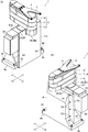
- FIG. 1 is a perspective view of an industrial robot 1 according to an embodiment of the present invention, in which (A) shows the industrial robot 1 from the front side, and (B) shows the industrial robot 1 from the back side.
- FIG. FIG. 2 is a perspective view of the industrial robot 1 shown in FIG. 1 in a state where the lifting body 20 is raised.
- FIG. 3 is a schematic plan view of a semiconductor manufacturing system 9 in which the industrial robot 1 shown in FIG. 1 is used.
- the industrial robot 1 (hereinafter referred to as “robot 1”) of the present embodiment is a horizontal multi-portion for transporting a semiconductor wafer 2 (see FIG. 3, hereinafter referred to as “wafer 2”), which is an object to be transferred. It is a joint robot.
- the robot 1 includes two hands 4 and 5 on which a wafer 2 is mounted, an arm 6 in which the hands 4 and 5 are pivotally connected to the distal end side and move in a horizontal direction, and a base end of the arm 6 And a main body portion 7 whose sides are rotatably connected.
- the robot 1 also includes an installation member 8 for installing the main body 7 on the floor surface (specifically, a floor surface 14b of a casing 14 described later).
- one horizontal direction is defined as the left-right direction
- the direction orthogonal to the up-down direction (vertical direction) and the left-right direction is defined as the front-rear direction.
- the X1 direction side in FIG. 1 or the like which is one side in the left-right direction is the “right” side
- the X2 direction side in FIG. is the “front” side
- the opposite Y2 direction side in FIG. 1 and the like is the “rear” side.
- the robot 1 is used by being incorporated in a semiconductor manufacturing system 9.
- the semiconductor manufacturing system 9 includes an EFEM 10 and a semiconductor wafer processing apparatus 11 that performs predetermined processing on the wafer 2.
- the EFEM 10 is disposed on the front side of the semiconductor wafer processing apparatus 11.
- the robot 1 constitutes a part of the EFEM 10.
- the EFEM 10 includes a plurality of load ports 13 that open and close the FOUP 12 and a housing 14 in which the robot 1 is accommodated.
- the housing 14 is formed in a rectangular parallelepiped box shape in the left-right direction.
- the load port 13 is disposed, for example, on the front side of the housing 14.
- the robot 1 is arranged inside the housing 14 so that the base end side of the arm 6 is adjacent to the front side surface 14 a inside the housing 14. Further, the robot 1 carries the wafer 2 between the FOUP 12 and the semiconductor wafer processing apparatus 11.
- the robot 1 may be disposed inside the housing 14 such that the proximal end side of the arm 6 is adjacent to the rear side surface inside the housing 14.
- the arm 6 has a first arm part 16 whose base end side is rotatably connected to the main body part 7, and a second arm part 17 whose base end side is rotatably connected to the distal end side of the first arm part 16.
- the third arm portion 18 is connected to the distal end side of the second arm portion 17 so that the proximal end side is rotatably connected.
- the first arm part 16, the second arm part 17, and the third arm part 18 are formed in a hollow shape.
- the main body part 7, the first arm part 16, the second arm part 17, and the third arm part 18 are arranged in this order from the lower side in the vertical direction.
- the hands 4 and 5 are formed so that the shape when viewed in the vertical direction is substantially Y-shaped.
- the base end side portions of the hands 4 and 5 are rotatably connected to the distal end side of the third arm portion 18.
- the hands 4 and 5 are arranged so as to overlap in the vertical direction. Specifically, the hand 4 is disposed on the upper side and the hand 5 is disposed on the lower side. Further, the hands 4 and 5 are disposed above the third arm portion 18.
- illustration of the hand 5 is abbreviate
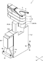
- FIG. 4 is a side view of the robot 1 shown in FIG.
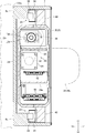
- FIG. 5 is a cross-sectional view for explaining the configuration of the EE cross section of FIG.
- illustration of the installation member 8 is abbreviate
- the main body 7 includes an elevating body 20 in which the base end side of the arm 6 is pivotally connected to the upper surface side, a housing 21 that holds the elevating body 20 so as to be movable up and down, and raises and lowers the elevating body 20 relative to the housing 21.
- An elevating mechanism 22 (see FIG. 5) and a guide mechanism 23 (see FIG. 5) for guiding the elevating body 20 in the vertical direction are provided.
- the main body 7 includes a wiring box (cable box) 24 in which wiring is accommodated. In FIGS. 4 and 5, the wiring box 24 is not shown.
- the housing 21 is formed in a flat, substantially rectangular parallelepiped box shape, and the shape of the housing 21 when viewed from above and below is a substantially rectangular shape with the left-right direction as the longitudinal direction and the front-rear direction as the short direction. Yes. Specifically, the shape of the housing 21 when viewed from above and below is a substantially rectangular shape elongated in the left and right direction.
- the front surface and the rear surface of the housing 21 are planes orthogonal to the front-rear direction, and the left and right side surfaces of the housing 21 are planes orthogonal to the left-right direction.
- the upper surface and bottom surface of the housing 21 are planes orthogonal to the vertical direction.
- the wiring box 24 is formed in a rectangular parallelepiped box shape.
- the wiring box 24 is fixed to the left side surface of the housing 21.
- the wiring box 24 is fixed to the upper end side of the housing 21.
- Various connectors (not shown) are arranged on the left side surface of the wiring box 24.
- the elevating body 20 includes a frame portion 25 formed in a flat and substantially rectangular parallelepiped shape, and an upper end side frame portion 26 fixed to the upper end side of the frame portion 25.
- the frame portion 25 and the upper end side frame portion 26 are formed separately and are fixed to each other. Specifically, the frame part 25 and the upper end side frame part 26 are fixed to each other by screws not shown.
- the frame portion 25 is formed in a box shape with an open bottom, and the shape of the frame portion 25 when viewed from the top and bottom is a substantially rectangular shape with the left-right direction as the longitudinal direction and the front-rear direction as the short direction. Yes. Specifically, the shape of the frame portion 25 when viewed from the up-down direction is a substantially rectangular shape elongated in the left-right direction.
- the front surface and the rear surface of the frame portion 25 are planes orthogonal to the front-rear direction, and the left and right side surfaces of the frame portion 25 are planes orthogonal to the left-right direction.
- the upper surface of the frame portion 25 is a plane orthogonal to the vertical direction.
- the width in the front-rear direction of the frame 25 is narrower than the width in the front-rear direction of the housing 21, and the width in the left-right direction of the frame 25 is narrower than the width in the left-right direction of the housing 21.
- the upper end side frame portion 26 is formed in a substantially rectangular parallelepiped shape.
- the upper end side frame portion 26 is formed so as to have a substantially rectangular shape when viewed in the vertical direction, with the longitudinal direction as the longitudinal direction and the lateral direction as the short direction.
- the upper end side frame part 26 is formed in the hollow shape.
- the width of the upper end side frame portion 26 in the left-right direction is narrower than the width of the frame portion 25 in the left-right direction.
- the upper end side frame portion 26 includes a fixed portion 26 a that is fixed to the frame portion 25.
- the fixed portion 26 a is accommodated in a recess formed at the center in the left-right direction on the upper end side of the frame portion 25.
- the upper end side frame part 26 is provided with the protrusion part 26b which protrudes from the front surface of the frame part 25 to the front side while connecting with the front end of the to-be-fixed part 26a.
- the base end side of the arm 6 is disposed on the upper surface side of the protruding portion 26b, and is rotatably connected to the protruding portion 26b.
- the frame portion 25 is accommodated in the housing 21. Specifically, when the elevating body 20 is lowered to the lower limit position (in the state shown in FIG. 1), the entire frame portion 25 is accommodated in the housing 21. That is, when the elevating body 20 is lowered to the lower limit position, a portion other than the protruding portion 26 b of the elevating body 20 is accommodated in the housing 21.
- the elevating body 20 when the elevating body 20 is raised from the lower limit position (in the state shown in FIG. 2), the lower end side portion of the frame portion 25 is accommodated in the housing 21. That is, when the elevating body 20 is rising from the lower limit position, the lower end side portion of the elevating body 20 is accommodated in the housing 21.
- a cutout portion 21a (see FIG. 2) in which the protruding portion 26b is disposed when the elevating body 20 is lowered is formed on the upper end side of the front surface portion of the housing 21. Note that a cutout portion through which the frame portion 25 passes when the elevating body 20 is raised and lowered is formed on the upper surface portion of the housing 21.
- the elevating mechanism 22 is accommodated in the casing 21.
- the lifting mechanism 22 includes a motor 28 and a ball screw 29.
- the ball screw 29 includes a screw shaft 30 that is rotated by the power of the motor 28 and a nut 31 that engages with the screw shaft 30.
- the motor 28 is housed in the housing 21 and is fixed to the lower end side of the housing 21. Further, the motor 28 is disposed at a substantially central position of the housing 21 in the left-right direction.
- the screw shaft 30 is disposed so that the axial direction of the screw shaft 30 and the vertical direction coincide with each other. Further, the screw shaft 30 is arranged on the right side of the motor 28.
- the screw shaft 30 is rotatably held by the housing 21.
- the nut 31 is fixed to the nut holding member 32.
- the nut holding member 32 is fixed inside the frame portion 25. That is, the nut 31 is fixed inside the frame portion 25 via the nut holding member 32.
- a pulley 33 is fixed to the output shaft of the motor 28, and a pulley 34 is fixed to the lower end side of the screw shaft 30.
- a belt 35 is stretched between the pulley 33 and the pulley 34.
- the elevating mechanism 22 is accommodated in the casing 21 so as to overlap the elevating body 20 when viewed from the vertical direction.
- the elevating mechanism 22 is accommodated in the housing 21 so as to overlap the frame portion 25 when viewed from the vertical direction.
- the guide mechanism 23 includes a guide rail 38 and a guide block 39 that engages with the guide rail 38.
- the guide rail 38 is fixed inside the housing 21 so that the longitudinal direction of the guide rail 38 coincides with the vertical direction.
- the guide rails 38 are fixed to the left and right end sides inside the housing 21.
- the guide block 39 is fixed to the block holding member 40.
- the block holding member 40 is fixed to each of the left and right side surfaces of the frame portion 25. That is, the guide block 39 is fixed to the left and right side surfaces of the frame portion 25 via the block holding member 40, and the guide rail 38 and the guide block 39 are disposed on both outer sides of the frame portion 25 in the left-right direction. Yes. Further, the guide rail 38 and the guide block 39 are accommodated in the housing 21.
- the elevating body 20 moves up and down with respect to the casing 21 while being guided by the guide mechanism 23.
- a cable bear (registered trademark) 42 is fixed inside the frame portion 25, and the other end side of the cable bear (registered trademark) 42 is fixed inside the housing 21.
- the cable bear (registered trademark) 42 is disposed on the left side of the motor 28.
- the robot 1 rotates the first arm portion 16 and the second arm portion 17 to expand and contract part of the arm 6 composed of the first arm portion 16 and the second arm portion 17 (FIG. 4).
- Reference a third arm drive mechanism (not shown) for rotating the third arm 18, a hand drive mechanism (not shown) for rotating the hand 4, and a hand drive mechanism for rotating the hand 5 (not shown). (Not shown).
- the arm unit drive mechanism 45 includes a motor 46, a speed reducer 47 that decelerates the power of the motor 46 and transmits the power to the first arm unit 16, and decelerates the power of the motor 46.
- a reduction gear 48 for transmitting to the two-arm portion 17 is provided.
- the motor 46 is fixed to the lower surface portion of the fixed portion 26 a of the upper end side frame portion 26.
- the output shaft of the motor 46 is disposed inside the fixed portion 26 a, and the main body portion of the motor 46 is disposed inside the frame portion 25.
- the speed reducer 47 constitutes a joint portion that connects the first arm portion 16 and the protruding portion 26b.
- the speed reducer 47 is a hollow speed reducer.
- the case body of the speed reducer 47 is fixed inside the protruding portion 26b.
- the upper end surface of the output shaft of the speed reducer 47 is fixed to the lower surface on the base end side of the first arm portion 16.
- the motor 46 and the speed reducer 47 are connected via a pulley 49 fixed to the output shaft of the motor 46, a pulley 50 fixed to the input shaft of the speed reducer 47, and a belt 51 spanned between the pulley 49 and the pulley 50. Are connected.
- the speed reducer 48 constitutes a joint portion that connects the first arm portion 16 and the second arm portion 17. Similar to the speed reducer 47, the speed reducer 48 is a hollow speed reducer.
- the motor 46 and the speed reducer 48 are connected via pulleys 49 and 50, a belt 51, a pulley disposed in the first arm portion 16, a belt (not shown), and the like.
- the third arm unit drive mechanism includes a motor and a speed reducer for decelerating the power of the motor and transmitting it to the third arm unit 18.
- the motor of the third arm unit driving mechanism is disposed inside the second arm unit 17, and the speed reducer of the third arm unit driving mechanism forms a joint unit that connects the second arm unit 17 and the third arm unit 18. is doing.
- the hand drive mechanism includes a motor and a speed reducer for decelerating the power of the motor and transmitting it to the hands 4 and 5.
- the motor and the speed reducer of the hand drive mechanism are disposed inside the third arm portion 18. Further, the speed reducer of the hand drive mechanism and the hands 4 and 5 are connected via a pulley and a belt (not shown).
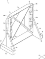
- FIG. 6 is a perspective view of the installation member 8 shown in FIG.
- the installation member 8 is a cast part made of aluminum alloy.
- the installation member 8 includes a housing fixing portion 8a to which the housing 21 is fixed. That is, in this embodiment, the casing 21 is fixed to the installation member 8.
- the installation member 8 includes two fixed portions 8b that are fixed to the floor surface 14b (see FIG. 3) of the housing 14 of the EFEM 10.
- the installation member 8 may be formed of a metal other than an aluminum alloy, or may be a cutting part or the like. Moreover, in FIG. 3, the installation member 8 is simplified and illustrated.
- the housing fixing part 8a is arranged on the rear side of the housing 14.
- the shape of the housing fixing portion 8a when viewed from the front-rear direction is substantially rectangular.
- the upper end of the housing fixing part 8 a is disposed below the upper end of the housing 21.
- the fixed portion 8b is connected to the lower end side of the housing fixing portion 8a.
- each of the two fixed portions 8b is connected to the lower end side of each of the left and right side surfaces of the housing fixing portion 8a.
- the two fixed portions 8b are arranged so as to sandwich the lower end portion of the housing 21 in the left-right direction. That is, one of the two fixed portions 8 b is fixed to the right side of the casing 21, and the other fixed portion 8 b is positioned to the left side of the casing 21.
- a contact surface 8c with which the rear surface of the housing 21 contacts is formed on the front surface side of the housing fixing portion 8a.
- the contact surface 8c is a plane orthogonal to the front-rear direction. Moreover, the contact surface 8c is formed in each of the both ends of the left-right direction of the front surface of the housing fixing
- the contact surface 8c protrudes slightly forward from the other part of the front surface of the housing fixing portion 8a.
- the front end portion of the fixed portion 8b protrudes forward from the front surface of the housing fixing portion 8a.
- Reinforcing ribs 8d that connect the front surface of the housing fixing portion 8a and the front end portion of the fixed portion 8b are formed at both ends in the left-right direction of the housing fixing portion 8a.
- the rib 8d is formed in a substantially triangular shape. Further, the two ribs 8d are disposed so as to sandwich the lower end portion of the casing 21 in the left-right direction.
- the housing 21 is fixed to the housing fixing portion 8a by a plurality of screws 54 (see FIG. 1B) with the rear surface of the housing 21 in contact with the contact surface 8c.
- the wiring box 24 is disposed above the rib 8d disposed on the left side.
- a plurality of through holes 8e through which the screws 54 are inserted are formed in a portion of the housing fixing portion 8a where the contact surface 8c is formed (see FIG. 6). The through hole 8e passes through the housing fixing portion 8a in the front-rear direction.
- the installation member 8 is fixed to the floor surface 14b by a plurality of screws 55 in a state where the lower surface of the fixed portion 8b is in contact with the floor surface 14b. That is, the robot 1 is installed on the floor surface 14b.
- the fixed portion 8b is formed with a plurality of through holes 8f through which the screws 55 are inserted (see FIG. 6). The through hole 8f penetrates the fixed portion 8b in the vertical direction.
- the lifting mechanism 22 is housed in the housing 21 so as to overlap the frame portion 25 housed in the housing 21 when viewed from the vertical direction. Therefore, in this embodiment, the width of the casing 21 in the front-rear direction can be reduced compared to the case where the elevating mechanism 22 is accommodated in the casing 21 in a state shifted from the frame portion 25 in the front-rear direction. Become. That is, in this embodiment, the width of the main body portion 7 in the front-rear direction can be reduced as compared with the case where the elevating mechanism 22 is housed in the casing 21 in a state shifted from the frame portion 25 in the front-rear direction. As a result, the main body 7 can be thinned.
- the robot 1 of this embodiment since the robot 1 of this embodiment includes the installation member 8 for installing the main body 7 on the floor surface 14b, even if the main body 7 is thinned, the installation state of the main body 7 with respect to the floor 14b. Can be stabilized. That is, in this embodiment, even if the main body 7 is thinned, the installation state of the robot 1 with respect to the floor surface 14b can be stabilized. Further, in this embodiment, since the wiring box 24 is fixed to the upper end side of the housing 21, interference between the fixed portion 8 b and the rib 8 d disposed outside the housing 21 in the left-right direction and the wiring box 24. Can be prevented.
- FIG. 7A is a perspective view of a robot 1 according to another embodiment of the present invention
- FIG. 7B is a diagram showing the lifting body 20 and the casing 21 of the robot 1 shown in FIG. It is a perspective view of the state which has risen.
- the robot 1 may include a lifting unit 60 that lifts and lowers the main body unit 7.
- the lifting / lowering unit 60 includes a lifting / lowering body (not shown) to which the casing 21 is fixed, a casing 61 as a second casing that holds the lifting / lowering body so as to be able to be lifted / lowered, and an elevating mechanism ( (Not shown), a guide mechanism (not shown) for guiding the elevating body in the up and down direction, and a wiring box 64 in which the wiring is accommodated.
- the elevating unit 60 is arranged on the front side of the housing fixing part 8 a, and the main body part 7 is arranged on the front side of the elevating unit 60.
- the casing 61 is formed in a flat, substantially rectangular parallelepiped box like the casing 21, and the shape of the casing 61 when viewed from the top and bottom is the longitudinal direction in the left-right direction and the short direction in the front-rear direction. It has a substantially rectangular shape elongated in the left-right direction.
- the front surface and the rear surface of the housing 61 are planes orthogonal to the front-rear direction, the left and right side surfaces of the housing 61 are planes orthogonal to the left-right direction, and the top surface and the bottom surface of the housing 61 are vertically aligned. It is an orthogonal plane.
- the width of the case 61 in the left-right direction is equal to the width of the case 21 in the left-right direction.
- the height of the casing 61 (the height in the vertical direction) is equal to the height of the casing 21 (the height in the vertical direction).
- the width of the casing 61 in the front-rear direction is slightly smaller than the width of the casing 21 in the front-rear direction.
- the wiring box 64 is formed in a rectangular parallelepiped box shape, and is fixed to the upper end side of the left side surface of the housing 61.
- the lifting body of the lifting unit 60 includes a fixed portion to which the lower end portion of the rear surface of the housing 21 is fixed.
- the fixed portion is disposed on the front side of the housing 61 and is disposed outside the housing 61. Further, a portion of the lifting body other than the fixed portion is accommodated in the housing 61.
- the elevating mechanism of the elevating unit 60 is configured in substantially the same manner as the elevating mechanism 22, and is disposed in the housing 61 in substantially the same manner as the elevating mechanism 22 is disposed in the housing 21.
- the guide mechanism of the elevating unit 60 is configured in the same manner as the guide mechanism 23, and is disposed inside the housing 61 in substantially the same manner as the guide mechanism 23 is disposed inside the housing 21.
- the casing 61 is fixed to the installation member 8. Specifically, the casing 61 is fixed to the casing fixing portion 8a with a plurality of screws in a state where the rear surface of the casing 61 is in contact with the contact surface 8c. In a state where the casing 61 is fixed to the installation member 8, the upper end of the casing fixing portion 8 a is disposed below the upper end of the casing 61. Further, in a state where the housing 61 is fixed to the installation member 8, the wiring box 64 is disposed on the upper side of the rib 8d disposed on the left side. Further, the fixed portion 8b and the rib 8d are disposed outside the housings 21 and 61 in the left-right direction.
- the lifting body 20 when the lifting body 20 is lowered to the lower limit position, the entire frame portion 25 is accommodated in the casing 21, but when the lifting body 20 is lowered to the lower limit position, the frame The upper end portion of the portion 25 may protrude above the upper surface of the housing 21. Moreover, in the form mentioned above, the raising / lowering body 20 does not need to be provided with the protrusion part 26b.
- the two hands 4 and 5 are attached to the distal end side of the third arm portion 18, but one hand may be attached to the distal end side of the third arm portion 18.
- the arm 6 is configured by the three arm portions of the first arm portion 16, the second arm portion 17, and the third arm portion 18, but the arm 6 is configured by the two arm portions. It may be configured by four or more arm portions.
- the robot 1 is a robot for transporting the wafer 2, but the robot 1 may be a robot for transporting other transport objects such as a glass substrate for liquid crystal.
- Robot Industrial robot
- Wafer semiconductor wafer, transfer object
- Hands Arm
- Body portion Installation member 8a Housing fixing portion 8b Fixed portion 14b Floor surface 20
- Lifting body 21 Housing 22
- Lifting mechanism 24
- Wiring box 25
- Frame portion 60
- Lifting unit 61
Landscapes
- Engineering & Computer Science (AREA)
- Robotics (AREA)
- Mechanical Engineering (AREA)
- Manipulator (AREA)
- Container, Conveyance, Adherence, Positioning, Of Wafer (AREA)
Abstract
この産業用ロボットは、搬送対象物が搭載されるハンドと、ハンドが先端側に回動可能に連結されるアームと、アームの基端側が回動可能に連結される本体部7と、本体部7を床面に設置するための設置部材8とを備えている。本体部7は、アームの基端側が上面側に回動可能に連結される昇降体20と、昇降体20を昇降可能に保持するとともに昇降体20の少なくとも下端側の一部が収容される筐体21と、昇降体20を昇降させる昇降機構22とを備えている。この産業用ロボットでは、昇降機構22は、上下方向から見たときに、昇降体20と重なるように筐体21に収容されている。
Description
本発明は、半導体ウエハ等の搬送対象物を搬送する産業用ロボットに関する。
従来、FOUP(Front Open Unified Pod)と半導体ウエハ処理装置との間で半導体ウエハを搬送する水平多関節ロボットが知られている(たとえば、特許文献1参照)。特許文献1に記載の水平多関節ロボットは、EFEM(Equipment Front End Module)の一部を構成しており、EFEMの筐体の内部に配置されている。EFEMは、半導体ウエハ処理装置の前側に配置され、FOUPは、EFEMの前側に配置されている。EFEMの筐体は、前後方向を短手方向とし左右方向を長手方向とする細長い直方体の箱状に形成されている。
また、特許文献1に記載の水平多関節ロボットは、半導体ウエハが搭載される2個のハンドと、2個のハンドが先端側に回動可能に連結されるアームと、アームの基端側が回動可能に連結される本体部とを備えている。本体部は、上端にアームの基端側が回動可能に連結される柱状部材と、柱状部材を昇降可能に保持する筐体と、柱状部材を昇降させる昇降機構とを備えている。下降時の柱状部材は、筐体に収容されている。また、昇降機構は、筐体に収容されている。
上述のように、特許文献1に記載の水平多関節ロボットは、EFEMの筐体の内部に配置されている。EFEMの筐体の内部では、各種の配管や配線が引き回されることがある。EFEMの筐体の内部で、配管や配線の引き回しスペースを確保するためには、水平多関節ロボットの本体部は、前後方向において薄くなっていることが好ましい。
そこで、本発明の課題は、アームの基端側が回動可能に連結される本体部を薄型化することが可能な産業用ロボットを提供することにある。
上記の課題を解決するため、本発明の産業用ロボットは、搬送対象物が搭載されるハンドと、ハンドが先端側に回動可能に連結されるアームと、アームの基端側が回動可能に連結される本体部と、本体部を床面に設置するための設置部材とを備え、本体部は、アームの基端側が上面側に回動可能に連結される昇降体と、昇降体を昇降可能に保持するとともに昇降体の少なくとも下端側の一部が収容される筐体と、昇降体を昇降させる昇降機構とを備え、昇降機構は、上下方向から見たときに、昇降体と重なるように筐体に収容されていることを特徴とする。
本発明において、たとえば、筐体は、上下方向から見たときの形状が左右方向を長手方向とし前後方向を短手方向とする略長方形状となるように形成され、昇降体は、上下方向から見たときの形状が左右方向を長手方向とし前後方向を短手方向とする略長方形状となるように形成され昇降体の下降時に筐体に収容されるフレーム部を備えている。
本発明の産業用ロボットでは、本体部は、アームの基端側が上面側に回動可能に連結される昇降体と、昇降体の少なくとも下端側の一部が収容される筐体と、昇降体を昇降させる昇降機構とを備えており、昇降機構は、上下方向から見たときに、昇降体と重なるように筐体に収容されている。そのため、本発明では、たとえば、上下方向から見たときの形状が左右方向を長手方向とし前後方向を短手方向とする略長方形状となるように筐体が形成されているとすると、昇降機構が前後方向において昇降体とずれた状態で筐体に収容されている場合と比較して、前後方向における筐体の幅を狭くすることが可能になる。すなわち、本発明では、たとえば、昇降機構が前後方向において昇降体とずれた状態で筐体に収容されている場合と比較して、前後方向における本体部の幅を狭くすることが可能になり、その結果、本体部を薄型化することが可能になる。
ここで、本体部が薄型化されると、産業用ロボットを床面に設置する場合に、床面に対する本体部の設置状態が不安定になって床面に対する産業用ロボットの設置状態が不安定になるおそれがある。しかしながら、本発明の産業用ロボットは、本体部を床面に設置するための設置部材を備えている。そのため、本発明では、本体部が薄型化されても、床面に対する本体部の設置状態を安定させることが可能になり、その結果、床面に対する産業用ロボットの設置状態を安定させることが可能になる。
本発明において、たとえば、設置部材には、筐体が固定されている。また、本発明において、たとえば、筐体は、上下方向から見たときの形状が左右方向を長手方向とし前後方向を短手方向とする略長方形状となるように形成され、設置部材は、筐体が固定される筐体固定部と、床面に固定される2個の被固定部とを備え、筐体固定部は、前後方向における筐体の一方側に配置され、被固定部は、筐体固定部の下端側に繋がっており、2個の被固定部のうちの一方の被固定部は、左右方向における筐体の一方側に配置され、他方の被固定部は、左右方向における筐体の他方側に配置されている。
本発明において、たとえば、本体部は、左右方向における筐体の一方の側面に固定される配線箱を備え、配線箱は、筐体の上端側に固定されている。この場合には、左右方向において筐体の外側に配置される被固定部と、配線箱との干渉を防止することが可能になる。
本発明において、産業用ロボットは、本体部を昇降させる昇降ユニットを備え、設置部材には、昇降ユニットの筐体である第2筐体が固定されていても良い。この場合には、本体部に加えて昇降ユニットが薄型化されても、床面に対する本体部および昇降ユニットの設置状態を安定させることが可能になり、その結果、床面に対する産業用ロボットの設置状態を安定させることが可能になる。
以上のように、本発明の産業用ロボットでは、アームの基端側が回動可能に連結される本体部を薄型化することが可能になる。
以下、図面を参照しながら、本発明の実施の形態を説明する。
(産業用ロボットの全体構成)
図1は、本発明の実施の形態にかかる産業用ロボット1の斜視図であり、(A)は正面側から産業用ロボット1を示す図、(B)は背面側から産業用ロボット1を示す図である。図2は、図1に示す産業用ロボット1の、昇降体20が上昇している状態の斜視図である。図3は、図1に示す産業用ロボット1が使用される半導体製造システム9の概略平面図である。
図1は、本発明の実施の形態にかかる産業用ロボット1の斜視図であり、(A)は正面側から産業用ロボット1を示す図、(B)は背面側から産業用ロボット1を示す図である。図2は、図1に示す産業用ロボット1の、昇降体20が上昇している状態の斜視図である。図3は、図1に示す産業用ロボット1が使用される半導体製造システム9の概略平面図である。
本形態の産業用ロボット1(以下、「ロボット1」とする。)は、搬送対象物である半導体ウエハ2(図3参照、以下、「ウエハ2」とする。)を搬送するための水平多関節ロボットである。このロボット1は、ウエハ2が搭載される2個のハンド4、5と、ハンド4、5が先端側に回動可能に連結されるとともに水平方向に動作するアーム6と、アーム6の基端側が回動可能に連結される本体部7とを備えている。また、ロボット1は、本体部7を床面(具体的には、後述の筺体14の床面14b)に設置するための設置部材8を備えている。
以下の説明では、水平方向の一方向を左右方向とし、上下方向(鉛直方向)と左右方向とに直交する方向を前後方向とする。また、左右方向の一方側である図1等のX1方向側を「右」側、その反対側である図1等のX2方向側を「左」側、前後方向の一方側である図1等のY1方向側を「前」側、その反対側である図1等のY2方向側を「後ろ」側とする。
図3に示すように、ロボット1は、半導体製造システム9に組み込まれて使用される。この半導体製造システム9は、EFEM10と、ウエハ2に対して所定の処理を行う半導体ウエハ処理装置11とを備えている。EFEM10は、半導体ウエハ処理装置11の前側に配置されている。ロボット1は、EFEM10の一部を構成している。また、EFEM10は、FOUP12を開閉する複数のロードポート13と、ロボット1が収容される筺体14とを備えている。
筺体14は、左右方向に細長い直方体の箱状に形成されている。ロードポート13は、たとえば、筺体14の前側に配置されている。ロボット1は、筐体14の内部の前側面14aにアーム6の基端側が隣接するように筐体14の内部に配置されている。また、ロボット1は、FOUP12と半導体ウエハ処理装置11との間でウエハ2を搬送する。なお、ロボット1は、筐体14の内部の後側面にアーム6の基端側が隣接するように筐体14の内部に配置されていても良い。
アーム6は、基端側が本体部7に回動可能に連結される第1アーム部16と、第1アーム部16の先端側に基端側が回動可能に連結される第2アーム部17と、第2アーム部17の先端側に基端側が回動可能に連結される第3アーム部18とから構成されている。第1アーム部16、第2アーム部17および第3アーム部18は、中空状に形成されている。本体部7と第1アーム部16と第2アーム部17と第3アーム部18とは、上下方向において、下側からこの順番で配置されている。
ハンド4、5は、上下方向から見たときの形状が略Y形状となるように形成されている。ハンド4、5の基端側部分は、第3アーム部18の先端側に回動可能に連結されている。また、ハンド4、5は、上下方向で重なるように配置されている。具体的には、ハンド4が上側に配置され、ハンド5が下側に配置されている。また、ハンド4、5は、第3アーム部18よりも上側に配置されている。なお、図3では、ハンド5の図示を省略している。
(本体部の構成)
図4は、図1に示すロボット1の側面図である。図5は、図4のE-E断面の構成を説明するための断面図である。なお、図4では、設置部材8の図示を省略している。
図4は、図1に示すロボット1の側面図である。図5は、図4のE-E断面の構成を説明するための断面図である。なお、図4では、設置部材8の図示を省略している。
本体部7は、アーム6の基端側が上面側に回動可能に連結される昇降体20と、昇降体20を昇降可能に保持する筺体21と、筺体21に対して昇降体20を昇降させる昇降機構22(図5参照)と、昇降体20を上下方向へ案内するガイド機構23(図5参照)とを備えている。また、本体部7は、配線が収容される配線箱(ケーブルボックス)24を備えている。なお、図4、図5では、配線箱24の図示を省略している。
筺体21は、扁平な略直方体の箱状に形成されており、上下方向から見たときの筺体21の形状は、左右方向を長手方向とし前後方向を短手方向とする略長方形状となっている。具体的には、上下方向から見たときの筺体21の形状は、左右方向に細長い略長方形状となっている。筺体21の前面および後面は、前後方向に直交する平面となっており、筺体21の左右の両側面は、左右方向に直交する平面となっている。また、筺体21の上面および底面は、上下方向に直交する平面となっている。
配線箱24は、直方体の箱状に形成されている。この配線箱24は、筺体21の左側面に固定されている。また、配線箱24は、筺体21の上端側に固定されている。配線箱24の左側面には、各種のコネクタ(図示省略)が配置されている。
昇降体20は、扁平な略直方体に形成されるフレーム部25と、フレーム部25の上端側に固定される上端側フレーム部26とを備えている。フレーム部25と上端側フレーム部26とは別体で形成され、互いに固定されている。具体的には、フレーム部25と上端側フレーム部26とは、図示を省略するネジによって互いに固定されている。
フレーム部25は、底面が開口する箱状に形成されており、上下方向から見たときのフレーム部25の形状は左右方向を長手方向とし前後方向を短手方向とする略長方形状となっている。具体的には、上下方向から見たときのフレーム部25の形状は、左右方向に細長い略長方形状となっている。フレーム部25の前面および後面は、前後方向に直交する平面となっており、フレーム部25の左右の両側面は、左右方向に直交する平面となっている。また、フレーム部25の上面は、上下方向に直交する平面となっている。フレーム25の前後方向の幅は、筺体21の前後方向の幅よりも狭くなっており、フレーム25の左右方向の幅は、筺体21の左右方向の幅よりも狭くなっている。
上端側フレーム部26は、略直方体状に形成されている。この上端側フレーム部26は、上下方向から見たときの形状が前後方向を長手方向とし左右方向を短手方向とする略長方形状となるように形成されている。また、上端側フレーム部26は、中空状に形成されている。上端側フレーム部26の左右方向の幅はフレーム部25の左右方向の幅よりも狭くなっている。
上端側フレーム部26は、フレーム部25に固定される被固定部26aを備えている。被固定部26aは、フレーム部25の上端側の左右方向の中心に形成される凹部の中に収容されている。また、上端側フレーム部26は、被固定部26aの前端に繋がるとともにフレーム部25の前面から前側へ突出する突出部26bを備えている。アーム6の基端側は、突出部26bの上面側に配置されており、突出部26bに回動可能に連結されている。
昇降体20の下降時には、フレーム部25は筐体21に収容されている。具体的には、昇降体20が下限位置まで下降しているとき(図1に示す状態のとき)には、フレーム部25の全体が筐体21に収容されている。すなわち、昇降体20が下限位置まで下降しているときには、昇降体20の、突出部26b以外の部分が筐体21に収容されている。
また、昇降体20が下限位置から上昇しているとき(図2に示す状態のとき)には、フレーム部25の下端側部分が筐体21に収容されている。すなわち、昇降体20が下限位置から上昇しているときには、昇降体20の下端側部分が筐体21に収容されている。筐体21の前面部の上端側には、昇降体20が下降しているときに突出部26bが配置される切欠き部21a(図2参照)が形成されている。なお、筐体21の上面部には、昇降体20の昇降時にフレーム部25が通過する切欠き部が形成されている。
昇降機構22は、筐体21に収容されている。この昇降機構22は、図5に示すように、モータ28とボールネジ29とを備えている。ボールネジ29は、モータ28の動力で回転するネジ軸30と、ネジ軸30に係合するナット31とを備えている。モータ28は、筐体21に収容されており、筐体21の下端側に固定されている。また、モータ28は、左右方向における筐体21の略中心位置に配置されている。ネジ軸30は、ネジ軸30の軸方向と上下方向とが一致するように配置されている。また、ネジ軸30は、モータ28よりも右側に配置されている。ネジ軸30は、筐体21に回転可能に保持されている。
ナット31は、ナット保持部材32に固定されている。ナット保持部材32は、フレーム部25の内部に固定されている。すなわち、ナット31は、ナット保持部材32を介してフレーム部25の内部に固定されている。モータ28の出力軸には、プーリ33が固定され、ネジ軸30の下端側には、プーリ34が固定されている。プーリ33とプーリ34とには、ベルト35が架け渡されている。図5に示すように、昇降機構22は、上下方向から見たときに、昇降体20と重なるように筐体21に収容されている。具体的には、昇降機構22は、上下方向から見たときに、フレーム部25と重なるように筐体21に収容されている。
ガイド機構23は、ガイドレール38と、ガイドレール38に係合するガイドブロック39とを備えている。ガイドレール38は、ガイドレール38の長手方向と上下方向とが一致するように筐体21の内部に固定されている。また、ガイドレール38は、筐体21の内部の左右の両端側に固定されている。ガイドブロック39は、ブロック保持部材40に固定されている。ブロック保持部材40は、フレーム部25の左右の両側面のそれぞれに固定されている。すなわち、ガイドブロック39は、ブロック保持部材40を介してフレーム部25の左右の両側面に固定されており、ガイドレール38およびガイドブロック39は、左右方向におけるフレーム部25の両外側に配置されている。また、ガイドレール38およびガイドブロック39は、筐体21に収容されている。
本形態では、モータ28が回転すると、昇降体20は、ガイド機構23に案内されながら筐体21に対して上下動する。なお、フレーム部25の内部には、ケーブルベア(登録商標)42の一端側が固定され、筐体21の内部には、ケーブルベア(登録商標)42の他端側が固定されている。ケーブルベア(登録商標)42は、モータ28よりも左側に配置されている。
(アームおよびハンドの駆動機構の構成)
ロボット1は、第1アーム部16および第2アーム部17を回動させて第1アーム部16と第2アーム部17とからなるアーム6の一部を伸縮させるアーム部駆動機構45(図4参照)と、第3アーム部18を回動させる第3アーム部駆動機構(図示省略)と、ハンド4を回動させるハンド駆動機構(図示省略)と、ハンド5を回動させるハンド駆動機構(図示省略)とを備えている。
ロボット1は、第1アーム部16および第2アーム部17を回動させて第1アーム部16と第2アーム部17とからなるアーム6の一部を伸縮させるアーム部駆動機構45(図4参照)と、第3アーム部18を回動させる第3アーム部駆動機構(図示省略)と、ハンド4を回動させるハンド駆動機構(図示省略)と、ハンド5を回動させるハンド駆動機構(図示省略)とを備えている。
アーム部駆動機構45は、図4に示すように、モータ46と、モータ46の動力を減速して第1アーム部16に伝達するための減速機47と、モータ46の動力を減速して第2アーム部17に伝達するための減速機48とを備えている。モータ46は、上端側フレーム部26の被固定部26aの下面部に固定されている。モータ46の出力軸は、被固定部26aの内部に配置され、モータ46の本体部は、フレーム部25の内部に配置されている。
減速機47は、第1アーム部16と突出部26bとを繋ぐ関節部を構成している。この減速機47は、中空減速機である。減速機47のケース体は、突出部26bの内部に固定されている。減速機47の出力軸の上端面は、第1アーム部16の基端側の下面に固定されている。モータ46と減速機47とは、モータ46の出力軸に固定されるプーリ49と、減速機47の入力軸に固定されるプーリ50と、プーリ49とプーリ50とに架け渡されるベルト51を介して連結されている。
減速機48は、第1アーム部16と第2アーム部17とを繋ぐ関節部を構成している。この減速機48は、減速機47と同様に、中空減速機である。モータ46と減速機48とは、プーリ49、50、ベルト51および第1アーム部16の内部に配置されるプーリ、ベルト(図示省略)等を介して連結されている。
第3アーム部駆動機構は、モータと、このモータの動力を減速して第3アーム部18に伝達するための減速機とを備えている。第3アーム部駆動機構のモータは、第2アーム部17の内部に配置され、第3アーム部駆動機構の減速機は、第2アーム部17と第3アーム部18とを繋ぐ関節部を構成している。ハンド駆動機構は、モータと、このモータの動力を減速してハンド4、5に伝達するための減速機とを備えている。ハンド駆動機構のモータおよび減速機は、第3アーム部18の内部に配置されている。また、ハンド駆動機構の減速機とハンド4、5とは、図示を省略するプーリおよびベルトを介して連結されている。
(設置部材の構成)
図6は、図1に示す設置部材8の斜視図である。
図6は、図1に示す設置部材8の斜視図である。
設置部材8は、アルミニウム合金製の鋳物部品である。この設置部材8は、筺体21が固定される筺体固定部8aを備えている。すなわち、本形態では、設置部材8に筐体21が固定されている。また、設置部材8は、EFEM10の筺体14の床面14b(図3参照)に固定される2個の被固定部8bを備えている。なお、設置部材8は、アルミニウム合金以外の金属で形成されていても良いし、切削部品等であっても良い。また、図3では、設置部材8を簡略化して図示している。
筺体固定部8aは、筺体14の後ろ側に配置されている。前後方向から見たときの筺体固定部8aの形状は、略長方形状となっている。筺体固定部8aの上端は、筺体21の上端よりも下側に配置されている。被固定部8bは、筐体固定部8aの下端側に繋がっている。具体的には、2個の被固定部8bのそれぞれは、筺体固定部8aの左右の両側面のそれぞれの下端側に繋がっている。また、2個の被固定部8bは、筺体21の下端部を左右方向で挟むように配置されている。すなわち、2個の被固定部8bのうちの一方の被固定部8bは、筐体21の右側に配置され、他方の被固定部8bは、筐体21の左側に配置されている。
筺体固定部8aの前面側には、筺体21の後面が接触する接触面8cが形成されている。接触面8cは、前後方向に直交する平面となっている。また、接触面8cは、筺体固定部8aの前面の、左右方向の両端側のそれぞれに形成されている。接触面8cは、筺体固定部8aの前面の他の部分よりもわずかに前側に突出している。被固定部8bの前端部は、筺体固定部8aの前面よりも前側に突出している。筺体固定部8aの左右方向の両端には、筺体固定部8aの前面と被固定部8bの前端部とを繋ぐ補強用のリブ8dが形成されている。リブ8dは、略三角形状に形成されている。また、2個のリブ8dは、筺体21の下端部を左右方向で挟むように配置されている。
筺体21は、図5に示すように、筺体21の後面が接触面8cに接触した状態で複数のネジ54(図1(B)参照)によって筺体固定部8aに固定されている。筺体21が設置部材8に固定された状態では、配線箱24は、左側に配置されるリブ8dの上側に配置されている。筺体固定部8aの、接触面8cが形成された部分には、ネジ54が挿通される複数の貫通穴8eが形成されている(図6参照)。貫通穴8eは、前後方向で筺体固定部8aを貫通している。
また、設置部材8は、被固定部8bの下面が床面14bに接触した状態で複数のネジ55によって床面14bに固定されている。すなわち、ロボット1は、床面14bに設置されている。被固定部8bには、ネジ55が挿通される複数の貫通穴8fが形成されている(図6参照)。貫通穴8fは、上下方向で被固定部8bを貫通している。
(本形態の主な効果)
以上説明したように、本形態では、昇降機構22は、上下方向から見たときに、筐体21に収容されるフレーム部25と重なるように筐体21に収容されている。そのため、本形態では、昇降機構22が前後方向においてフレーム部25とずれた状態で筐体21に収容されている場合と比較して、前後方向における筐体21の幅を狭くすることが可能になる。すなわち、本形態では、昇降機構22が前後方向においてフレーム部25とずれた状態で筐体21に収容されている場合と比較して、前後方向における本体部7の幅を狭くすることが可能になり、その結果、本体部7を薄型化することが可能になる。
以上説明したように、本形態では、昇降機構22は、上下方向から見たときに、筐体21に収容されるフレーム部25と重なるように筐体21に収容されている。そのため、本形態では、昇降機構22が前後方向においてフレーム部25とずれた状態で筐体21に収容されている場合と比較して、前後方向における筐体21の幅を狭くすることが可能になる。すなわち、本形態では、昇降機構22が前後方向においてフレーム部25とずれた状態で筐体21に収容されている場合と比較して、前後方向における本体部7の幅を狭くすることが可能になり、その結果、本体部7を薄型化することが可能になる。
また、本形態のロボット1は、本体部7を床面14bに設置するための設置部材8を備えているため、本体部7が薄型化されても、床面14bに対する本体部7の設置状態を安定させることが可能になる。すなわち、本形態では、本体部7が薄型化されても、床面14bに対するロボット1の設置状態を安定させることが可能になる。また、本形態では、配線箱24が筐体21の上端側に固定されているため、左右方向において筐体21の外側に配置される被固定部8bおよびリブ8dと、配線箱24との干渉を防止することが可能になる。
(ロボットの変形例)
図7(A)は、本発明の他の実施の形態にかかるロボット1の斜視図であり、図7(B)は、図7(A)に示すロボット1の、昇降体20および筺体21が上昇している状態の斜視図である。
図7(A)は、本発明の他の実施の形態にかかるロボット1の斜視図であり、図7(B)は、図7(A)に示すロボット1の、昇降体20および筺体21が上昇している状態の斜視図である。
上述した形態において、ロボット1は、本体部7を昇降させる昇降させる昇降ユニット60を備えていても良い。昇降ユニット60は、筺体21が固定される昇降体(図示省略)と、この昇降体を昇降可能に保持する第2筺体としての筺体61と、筺体61に対して昇降体を昇降させる昇降機構(図示省略)と、昇降体を上下方向へ案内するガイド機構(図示省略)と、配線が収容される配線箱64とを備えている。昇降ユニット60は、筺体固定部8aの前側に配置され、本体部7は、昇降ユニット60の前側に配置されている。
筺体61は、筺体21と同様に、扁平な略直方体の箱状に形成されており、上下方向から見たときの筺体61の形状は、左右方向を長手方向とし前後方向を短手方向とする左右方向に細長い略長方形状となっている。筺体61の前面および後面は、前後方向に直交する平面となっており、筺体61の左右の両側面は、左右方向に直交する平面となっており、筺体61の上面および底面は、上下方向に直交する平面となっている。
筺体61の左右方向の幅は、筺体21の左右方向の幅と等しくなっている。また、筺体61の高さ(上下方向の高さ)は、筺体21の高さ(上下方向の高さ)と等しくなっている。また、筺体61の前後方向の幅は、筺体21の前後方向の幅よりも若干、狭くなっている。配線箱64は、直方体の箱状に形成されており、筺体61の左側面の上端側に固定されている。
昇降ユニット60の昇降体は、筺体21の後面の下端部が固定される被固定部を備えている。被固定部は、筺体61の前側に配置されるとともに、筺体61の外部に配置されている。また、昇降体の、被固定部以外の部分は、筺体61に収容されている。昇降ユニット60の昇降機構は、昇降機構22とほぼ同様に構成されており、昇降機構22が筺体21の内部に配置されているのとほぼ同様に、筺体61の内部に配置されている。また、昇降ユニット60のガイド機構は、ガイド機構23と同様に構成されており、ガイド機構23が筺体21の内部に配置されているのとほぼ同様に、筺体61の内部に配置されている。
この変形例では、筺体61が設置部材8に固定されている。具体的には、筺体61の後面が接触面8cに接触した状態で複数のネジによって筺体固定部8aに筺体61が固定されている。筺体61が設置部材8に固定された状態では、筺体固定部8aの上端は、筺体61の上端よりも下側に配置されている。また、筺体61が設置部材8に固定された状態では、配線箱64は、左側に配置されるリブ8dの上側に配置されている。また、被固定部8bおよびリブ8dは、左右方向において、筺体21、61の外側に配置されている。
この変形例では、昇降ユニット60の筺体61が設置部材8に固定され、かつ、設置部材8が床面14bに設置されているため、本体部7に加えて昇降ユニット60が薄型化されても、床面14bに対する本体部7および昇降ユニット60の設置状態を安定させることが可能になる。すなわち、本体部7に加えて昇降ユニット60が薄型化されても、床面14bに対するロボット1の設置状態を安定させることが可能になる。
(他の実施の形態)
上述した形態は、本発明の好適な形態の一例ではあるが、これに限定されるものではなく本発明の要旨を変更しない範囲において種々変形実施が可能である。
上述した形態は、本発明の好適な形態の一例ではあるが、これに限定されるものではなく本発明の要旨を変更しない範囲において種々変形実施が可能である。
上述した形態では、昇降体20が下限位置まで下降しているときに、フレーム部25の全体が筐体21に収容されているが、昇降体20が下限位置まで下降しているときに、フレーム部25の上端側部分が筐体21の上面よりも上側へ突出していても良い。また、上述した形態において、昇降体20は、突出部26bを備えていなくても良い。また、上述した形態では、第3アーム部18の先端側に2個のハンド4、5が取り付けられているが、第3アーム部18の先端側に1個のハンドが取り付けられても良い。
上述した形態では、アーム6は、第1アーム部16、第2アーム部17および第3アーム部18の3個のアーム部によって構成されているが、アーム6は、2個のアーム部によって構成されても良いし、4個以上のアーム部によって構成されていても良い。また、上述した形態では、ロボット1は、ウエハ2を搬送するためのロボットであるが、ロボット1は、液晶用のガラス基板等の他の搬送対象物を搬送するロボットであっても良い。
1 ロボット(産業用ロボット)
2 ウエハ(半導体ウエハ、搬送対象物)
4、5 ハンド
6 アーム
7 本体部
8 設置部材
8a 筐体固定部
8b 被固定部
14b 床面
20 昇降体
21 筐体
22 昇降機構
24 配線箱
25 フレーム部
60 昇降ユニット
61 筐体(第2筐体)
2 ウエハ(半導体ウエハ、搬送対象物)
4、5 ハンド
6 アーム
7 本体部
8 設置部材
8a 筐体固定部
8b 被固定部
14b 床面
20 昇降体
21 筐体
22 昇降機構
24 配線箱
25 フレーム部
60 昇降ユニット
61 筐体(第2筐体)
Claims (6)
- 搬送対象物が搭載されるハンドと、前記ハンドが先端側に回動可能に連結されるアームと、前記アームの基端側が回動可能に連結される本体部と、前記本体部を床面に設置するための設置部材とを備え、
前記本体部は、前記アームの基端側が上面側に回動可能に連結される昇降体と、前記昇降体を昇降可能に保持するとともに前記昇降体の少なくとも下端側の一部が収容される筐体と、前記昇降体を昇降させる昇降機構とを備え、
前記昇降機構は、上下方向から見たときに、前記昇降体と重なるように前記筐体に収容されていることを特徴とする産業用ロボット。 - 前記筐体は、上下方向から見たときの形状が左右方向を長手方向とし前後方向を短手方向とする略長方形状となるように形成され、
前記昇降体は、上下方向から見たときの形状が左右方向を長手方向とし前後方向を短手方向とする略長方形状となるように形成され前記昇降体の下降時に前記筐体に収容されるフレーム部を備えることを特徴とする請求項1記載の産業用ロボット。 - 前記設置部材には、前記筐体が固定されていることを特徴とする請求項1または2記載の産業用ロボット。
- 前記筐体は、上下方向から見たときの形状が左右方向を長手方向とし前後方向を短手方向とする略長方形状となるように形成され、
前記設置部材は、前記筐体が固定される筐体固定部と、前記床面に固定される2個の被固定部とを備え、
前記筐体固定部は、前後方向における前記筐体の一方側に配置され、
前記被固定部は、前記筐体固定部の下端側に繋がっており、
2個の前記被固定部のうちの一方の前記被固定部は、左右方向における前記筐体の一方側に配置され、他方の前記被固定部は、左右方向における前記筐体の他方側に配置されていることを特徴とする請求項3記載の産業用ロボット。 - 前記本体部は、左右方向における前記筐体の一方の側面に固定される配線箱を備え、
前記配線箱は、前記筐体の上端側に固定されていることを特徴とする請求項4記載の産業用ロボット。 - 前記本体部を昇降させる昇降ユニットを備え、
前記設置部材には、前記昇降ユニットの筐体である第2筐体が固定されていることを特徴とする請求項1または2記載の産業用ロボット。
Priority Applications (3)
| Application Number | Priority Date | Filing Date | Title |
|---|---|---|---|
| CN201780071876.7A CN109982816A (zh) | 2016-12-02 | 2017-11-06 | 工业用机器人 |
| US16/466,166 US20200061807A1 (en) | 2016-12-02 | 2017-11-06 | Industrial robot |
| TW106140034A TW201822968A (zh) | 2016-12-02 | 2017-11-20 | 產業用機器人 |
Applications Claiming Priority (2)
| Application Number | Priority Date | Filing Date | Title |
|---|---|---|---|
| JP2016-234797 | 2016-12-02 | ||
| JP2016234797A JP2018089739A (ja) | 2016-12-02 | 2016-12-02 | 産業用ロボット |
Publications (1)
| Publication Number | Publication Date |
|---|---|
| WO2018100973A1 true WO2018100973A1 (ja) | 2018-06-07 |
Family
ID=62242104
Family Applications (1)
| Application Number | Title | Priority Date | Filing Date |
|---|---|---|---|
| PCT/JP2017/039850 Ceased WO2018100973A1 (ja) | 2016-12-02 | 2017-11-06 | 産業用ロボット |
Country Status (5)
| Country | Link |
|---|---|
| US (1) | US20200061807A1 (ja) |
| JP (1) | JP2018089739A (ja) |
| CN (1) | CN109982816A (ja) |
| TW (1) | TW201822968A (ja) |
| WO (1) | WO2018100973A1 (ja) |
Families Citing this family (1)
| Publication number | Priority date | Publication date | Assignee | Title |
|---|---|---|---|---|
| JP2024004686A (ja) | 2022-06-29 | 2024-01-17 | ニデックインスツルメンツ株式会社 | 産業用ロボット |
Citations (5)
| Publication number | Priority date | Publication date | Assignee | Title |
|---|---|---|---|---|
| JPH11156772A (ja) * | 1997-12-01 | 1999-06-15 | Mecs Corp | 薄型基板の搬送ロボット |
| WO2009066573A1 (ja) * | 2007-11-21 | 2009-05-28 | Kabushiki Kaisha Yaskawa Denki | 搬送ロボット、それを備えた局所クリーン化された筐体、及びそれを備えた半導体製造装置 |
| JP2014069270A (ja) * | 2012-09-28 | 2014-04-21 | Nidec Sankyo Corp | 産業用ロボット |
| JP2014108497A (ja) * | 2012-12-04 | 2014-06-12 | Iai Corp | 直交ロボット |
| JP2015036184A (ja) * | 2013-08-09 | 2015-02-23 | 日本電産サンキョー株式会社 | 産業用ロボット |
Family Cites Families (21)
| Publication number | Priority date | Publication date | Assignee | Title |
|---|---|---|---|---|
| US4424473A (en) * | 1982-02-05 | 1984-01-03 | American Robot Corporation | Drive apparatus for an industrial robot |
| US4636138A (en) * | 1982-02-05 | 1987-01-13 | American Robot Corporation | Industrial robot |
| US5178512A (en) * | 1991-04-01 | 1993-01-12 | Equipe Technologies | Precision robot apparatus |
| US5954840A (en) * | 1996-06-13 | 1999-09-21 | Genmark Automation | Universally tiltable Z axis drive arm |
| JP2000042953A (ja) * | 1998-07-29 | 2000-02-15 | Janome Sewing Mach Co Ltd | 水平多関節ロボット |
| US6494666B2 (en) * | 2001-01-26 | 2002-12-17 | Fortrend Engineering Corporation | Simplified and enhanced SCARA arm |
| JP2002338042A (ja) * | 2001-05-15 | 2002-11-27 | Dainippon Screen Mfg Co Ltd | 基板処理装置および基板搬入搬出装置 |
| US7281741B2 (en) * | 2001-07-13 | 2007-10-16 | Semitool, Inc. | End-effectors for handling microelectronic workpieces |
| US6831436B2 (en) * | 2002-04-22 | 2004-12-14 | Jose Raul Gonzalez | Modular hybrid multi-axis robot |
| DE10349452A1 (de) * | 2003-10-23 | 2005-05-25 | Bosch Rexroth Ag | Roboter vom Scara-Typ |
| JP2006167864A (ja) * | 2004-12-16 | 2006-06-29 | Seiko Epson Corp | 水平多関節型ロボット |
| US8220354B2 (en) * | 2006-06-28 | 2012-07-17 | Genmark Automation, Inc. | Belt-driven robot having extended Z-axis motion |
| KR20100044987A (ko) * | 2008-10-23 | 2010-05-03 | 주식회사 나온테크 | 기판 이송로봇 및 이를 이용한 이송방법 |
| CN102049773B (zh) * | 2009-10-29 | 2013-08-28 | 鸿富锦精密工业(深圳)有限公司 | 平面关节型机器人 |
| JP2012056033A (ja) * | 2010-09-09 | 2012-03-22 | Sinfonia Technology Co Ltd | ロボットアーム装置 |
| JP5610952B2 (ja) * | 2010-09-24 | 2014-10-22 | 日本電産サンキョー株式会社 | 産業用ロボット |
| DE202011001965U1 (de) * | 2011-01-26 | 2011-06-09 | KUKA Roboter GmbH, 86165 | Montagesystem und Positioniervorrichtung eines Montagesystems |
| JP5364769B2 (ja) * | 2011-09-26 | 2013-12-11 | 株式会社安川電機 | 搬送ロボットおよび基板処理装置 |
| JP2013158849A (ja) * | 2012-02-01 | 2013-08-19 | Yaskawa Electric Corp | ロボット |
| KR20180008742A (ko) * | 2015-05-25 | 2018-01-24 | 카와사키 주코교 카부시키 카이샤 | 수평 다관절 로봇 |
| CN206536457U (zh) * | 2017-03-14 | 2017-10-03 | 合肥鑫晟光电科技有限公司 | 一种基板搬送机器人 |
-
2016
- 2016-12-02 JP JP2016234797A patent/JP2018089739A/ja active Pending
-
2017
- 2017-11-06 CN CN201780071876.7A patent/CN109982816A/zh not_active Withdrawn
- 2017-11-06 WO PCT/JP2017/039850 patent/WO2018100973A1/ja not_active Ceased
- 2017-11-06 US US16/466,166 patent/US20200061807A1/en not_active Abandoned
- 2017-11-20 TW TW106140034A patent/TW201822968A/zh unknown
Patent Citations (5)
| Publication number | Priority date | Publication date | Assignee | Title |
|---|---|---|---|---|
| JPH11156772A (ja) * | 1997-12-01 | 1999-06-15 | Mecs Corp | 薄型基板の搬送ロボット |
| WO2009066573A1 (ja) * | 2007-11-21 | 2009-05-28 | Kabushiki Kaisha Yaskawa Denki | 搬送ロボット、それを備えた局所クリーン化された筐体、及びそれを備えた半導体製造装置 |
| JP2014069270A (ja) * | 2012-09-28 | 2014-04-21 | Nidec Sankyo Corp | 産業用ロボット |
| JP2014108497A (ja) * | 2012-12-04 | 2014-06-12 | Iai Corp | 直交ロボット |
| JP2015036184A (ja) * | 2013-08-09 | 2015-02-23 | 日本電産サンキョー株式会社 | 産業用ロボット |
Also Published As
| Publication number | Publication date |
|---|---|
| JP2018089739A (ja) | 2018-06-14 |
| TW201822968A (zh) | 2018-07-01 |
| CN109982816A (zh) | 2019-07-05 |
| US20200061807A1 (en) | 2020-02-27 |
Similar Documents
| Publication | Publication Date | Title |
|---|---|---|
| JP6509487B2 (ja) | 産業用ロボット | |
| KR102612257B1 (ko) | 수평 다관절 로봇 및 제조 시스템 | |
| TW201343344A (zh) | 機器人 | |
| KR101246127B1 (ko) | 더블암식 삼단 카세트 이송 로봇 | |
| WO2012164994A1 (ja) | 引出し装置及び保管装置 | |
| JP2017035770A (ja) | 産業用ロボット | |
| WO2018100973A1 (ja) | 産業用ロボット | |
| KR102539037B1 (ko) | 산업용 로봇 | |
| JP6630162B2 (ja) | 産業用ロボット | |
| CN108172540A (zh) | 移载机 | |
| KR102612256B1 (ko) | 제조 시스템 | |
| KR102575400B1 (ko) | 산업용 로봇 | |
| KR102824300B1 (ko) | 수평 다관절 로봇 | |
| KR102954593B1 (ko) | Oht 시스템 | |
| KR20110131837A (ko) | 선형 기판이송장치를 갖는 기판처리시스템 | |
| KR101126160B1 (ko) | 기판 처리 장치 | |
| KR20240170461A (ko) | 산업용 로봇 |
Legal Events
| Date | Code | Title | Description |
|---|---|---|---|
| 121 | Ep: the epo has been informed by wipo that ep was designated in this application |
Ref document number: 17875247 Country of ref document: EP Kind code of ref document: A1 |
|
| NENP | Non-entry into the national phase |
Ref country code: DE |
|
| 122 | Ep: pct application non-entry in european phase |
Ref document number: 17875247 Country of ref document: EP Kind code of ref document: A1 |