WO2018100760A1 - 上肢動作支援装置及び上肢動作支援システム - Google Patents
上肢動作支援装置及び上肢動作支援システム Download PDFInfo
- Publication number
- WO2018100760A1 WO2018100760A1 PCT/JP2017/014594 JP2017014594W WO2018100760A1 WO 2018100760 A1 WO2018100760 A1 WO 2018100760A1 JP 2017014594 W JP2017014594 W JP 2017014594W WO 2018100760 A1 WO2018100760 A1 WO 2018100760A1
- Authority
- WO
- WIPO (PCT)
- Prior art keywords
- upper limb
- operator
- unit
- related data
- end effector
- Prior art date
Links
Images


Classifications
-
- B—PERFORMING OPERATIONS; TRANSPORTING
- B25—HAND TOOLS; PORTABLE POWER-DRIVEN TOOLS; MANIPULATORS
- B25J—MANIPULATORS; CHAMBERS PROVIDED WITH MANIPULATION DEVICES
- B25J11/00—Manipulators not otherwise provided for
- B25J11/008—Manipulators for service tasks
-
- B—PERFORMING OPERATIONS; TRANSPORTING
- B25—HAND TOOLS; PORTABLE POWER-DRIVEN TOOLS; MANIPULATORS
- B25J—MANIPULATORS; CHAMBERS PROVIDED WITH MANIPULATION DEVICES
- B25J9/00—Programme-controlled manipulators
- B25J9/16—Programme controls
- B25J9/1656—Programme controls characterised by programming, planning systems for manipulators
- B25J9/1664—Programme controls characterised by programming, planning systems for manipulators characterised by motion, path, trajectory planning
- B25J9/1666—Avoiding collision or forbidden zones
-
- A—HUMAN NECESSITIES
- A61—MEDICAL OR VETERINARY SCIENCE; HYGIENE
- A61H—PHYSICAL THERAPY APPARATUS, e.g. DEVICES FOR LOCATING OR STIMULATING REFLEX POINTS IN THE BODY; ARTIFICIAL RESPIRATION; MASSAGE; BATHING DEVICES FOR SPECIAL THERAPEUTIC OR HYGIENIC PURPOSES OR SPECIFIC PARTS OF THE BODY
- A61H1/00—Apparatus for passive exercising; Vibrating apparatus ; Chiropractic devices, e.g. body impacting devices, external devices for briefly extending or aligning unbroken bones
- A61H1/02—Stretching or bending or torsioning apparatus for exercising
- A61H1/0274—Stretching or bending or torsioning apparatus for exercising for the upper limbs
-
- B—PERFORMING OPERATIONS; TRANSPORTING
- B25—HAND TOOLS; PORTABLE POWER-DRIVEN TOOLS; MANIPULATORS
- B25J—MANIPULATORS; CHAMBERS PROVIDED WITH MANIPULATION DEVICES
- B25J13/00—Controls for manipulators
- B25J13/003—Controls for manipulators by means of an audio-responsive input
-
- B—PERFORMING OPERATIONS; TRANSPORTING
- B25—HAND TOOLS; PORTABLE POWER-DRIVEN TOOLS; MANIPULATORS
- B25J—MANIPULATORS; CHAMBERS PROVIDED WITH MANIPULATION DEVICES
- B25J13/00—Controls for manipulators
- B25J13/08—Controls for manipulators by means of sensing devices, e.g. viewing or touching devices
- B25J13/081—Touching devices, e.g. pressure-sensitive
- B25J13/082—Grasping-force detectors
-
- B—PERFORMING OPERATIONS; TRANSPORTING
- B25—HAND TOOLS; PORTABLE POWER-DRIVEN TOOLS; MANIPULATORS
- B25J—MANIPULATORS; CHAMBERS PROVIDED WITH MANIPULATION DEVICES
- B25J13/00—Controls for manipulators
- B25J13/08—Controls for manipulators by means of sensing devices, e.g. viewing or touching devices
- B25J13/085—Force or torque sensors
-
- B—PERFORMING OPERATIONS; TRANSPORTING
- B25—HAND TOOLS; PORTABLE POWER-DRIVEN TOOLS; MANIPULATORS
- B25J—MANIPULATORS; CHAMBERS PROVIDED WITH MANIPULATION DEVICES
- B25J13/00—Controls for manipulators
- B25J13/08—Controls for manipulators by means of sensing devices, e.g. viewing or touching devices
- B25J13/087—Controls for manipulators by means of sensing devices, e.g. viewing or touching devices for sensing other physical parameters, e.g. electrical or chemical properties
-
- B—PERFORMING OPERATIONS; TRANSPORTING
- B25—HAND TOOLS; PORTABLE POWER-DRIVEN TOOLS; MANIPULATORS
- B25J—MANIPULATORS; CHAMBERS PROVIDED WITH MANIPULATION DEVICES
- B25J15/00—Gripping heads and other end effectors
- B25J15/0028—Gripping heads and other end effectors with movable, e.g. pivoting gripping jaw surfaces
-
- B—PERFORMING OPERATIONS; TRANSPORTING
- B25—HAND TOOLS; PORTABLE POWER-DRIVEN TOOLS; MANIPULATORS
- B25J—MANIPULATORS; CHAMBERS PROVIDED WITH MANIPULATION DEVICES
- B25J19/00—Accessories fitted to manipulators, e.g. for monitoring, for viewing; Safety devices combined with or specially adapted for use in connection with manipulators
- B25J19/02—Sensing devices
- B25J19/021—Optical sensing devices
- B25J19/023—Optical sensing devices including video camera means
-
- B—PERFORMING OPERATIONS; TRANSPORTING
- B25—HAND TOOLS; PORTABLE POWER-DRIVEN TOOLS; MANIPULATORS
- B25J—MANIPULATORS; CHAMBERS PROVIDED WITH MANIPULATION DEVICES
- B25J9/00—Programme-controlled manipulators
- B25J9/06—Programme-controlled manipulators characterised by multi-articulated arms
-
- B—PERFORMING OPERATIONS; TRANSPORTING
- B25—HAND TOOLS; PORTABLE POWER-DRIVEN TOOLS; MANIPULATORS
- B25J—MANIPULATORS; CHAMBERS PROVIDED WITH MANIPULATION DEVICES
- B25J9/00—Programme-controlled manipulators
- B25J9/16—Programme controls
- B25J9/1628—Programme controls characterised by the control loop
- B25J9/163—Programme controls characterised by the control loop learning, adaptive, model based, rule based expert control
-
- B—PERFORMING OPERATIONS; TRANSPORTING
- B25—HAND TOOLS; PORTABLE POWER-DRIVEN TOOLS; MANIPULATORS
- B25J—MANIPULATORS; CHAMBERS PROVIDED WITH MANIPULATION DEVICES
- B25J9/00—Programme-controlled manipulators
- B25J9/16—Programme controls
- B25J9/1628—Programme controls characterised by the control loop
- B25J9/1633—Programme controls characterised by the control loop compliant, force, torque control, e.g. combined with position control
-
- B—PERFORMING OPERATIONS; TRANSPORTING
- B25—HAND TOOLS; PORTABLE POWER-DRIVEN TOOLS; MANIPULATORS
- B25J—MANIPULATORS; CHAMBERS PROVIDED WITH MANIPULATION DEVICES
- B25J9/00—Programme-controlled manipulators
- B25J9/16—Programme controls
- B25J9/1694—Programme controls characterised by use of sensors other than normal servo-feedback from position, speed or acceleration sensors, perception control, multi-sensor controlled systems, sensor fusion
- B25J9/1697—Vision controlled systems
-
- A—HUMAN NECESSITIES
- A61—MEDICAL OR VETERINARY SCIENCE; HYGIENE
- A61H—PHYSICAL THERAPY APPARATUS, e.g. DEVICES FOR LOCATING OR STIMULATING REFLEX POINTS IN THE BODY; ARTIFICIAL RESPIRATION; MASSAGE; BATHING DEVICES FOR SPECIAL THERAPEUTIC OR HYGIENIC PURPOSES OR SPECIFIC PARTS OF THE BODY
- A61H2201/00—Characteristics of apparatus not provided for in the preceding codes
- A61H2201/16—Physical interface with patient
- A61H2201/1657—Movement of interface, i.e. force application means
- A61H2201/1659—Free spatial automatic movement of interface within a working area, e.g. Robot
-
- G—PHYSICS
- G05—CONTROLLING; REGULATING
- G05B—CONTROL OR REGULATING SYSTEMS IN GENERAL; FUNCTIONAL ELEMENTS OF SUCH SYSTEMS; MONITORING OR TESTING ARRANGEMENTS FOR SUCH SYSTEMS OR ELEMENTS
- G05B2219/00—Program-control systems
- G05B2219/30—Nc systems
- G05B2219/39—Robotics, robotics to robotics hand
- G05B2219/39498—Each finger has force torque sensor in tip of finger
-
- G—PHYSICS
- G05—CONTROLLING; REGULATING
- G05B—CONTROL OR REGULATING SYSTEMS IN GENERAL; FUNCTIONAL ELEMENTS OF SUCH SYSTEMS; MONITORING OR TESTING ARRANGEMENTS FOR SUCH SYSTEMS OR ELEMENTS
- G05B2219/00—Program-control systems
- G05B2219/30—Nc systems
- G05B2219/40—Robotics, robotics mapping to robotics vision
- G05B2219/40202—Human robot coexistence
-
- G—PHYSICS
- G05—CONTROLLING; REGULATING
- G05B—CONTROL OR REGULATING SYSTEMS IN GENERAL; FUNCTIONAL ELEMENTS OF SUCH SYSTEMS; MONITORING OR TESTING ARRANGEMENTS FOR SUCH SYSTEMS OR ELEMENTS
- G05B2219/00—Program-control systems
- G05B2219/30—Nc systems
- G05B2219/40—Robotics, robotics mapping to robotics vision
- G05B2219/40411—Robot assists human in non-industrial environment like home or office
Definitions
- the present invention is suitable for application to, for example, an upper limb motion support device and an upper limb motion support system that can be operated by a hemiplegic person while collaborating with a healthy hand on a robot arm placed on a table.
- Measures currently being implemented include attempts to improve functions through rehabilitation and use welfare equipment for hemiplegic patients.
- paralysis of the upper limbs generally tends to be harder to recover than the lower limbs, with 14% of the total recovery reported and 25% of the partial recovery reported. That is, about 60% of all hemiplegics are in a state where no recovery is seen in upper limb function.
- a robot arm that understands the intention of the hemiplegic person and supports the movement in conjunction with a healthy upper limb can be considered.
- a robot arm for cooking work support in a kitchen a work arm position and work probability are obtained, and a waiting position is minimized to reduce time loss (see Patent Document 1).
- Patent Document 2 As a robot system for supporting tableware and lower tableware, a robot system that supports tableware using a visual sensor based on recorded information has been proposed (see Patent Document 2). Further, a suspension type cooperative work robot has been proposed that recognizes a relative position with respect to a robot arm while imaging a work target and performs work based on the relative position (see Patent Document 3).
- the present invention has been made in view of the above points, and intends to propose an upper limb motion support device and an upper limb motion support system capable of greatly improving the work efficiency of the operator and the reduction of the work load. Is.
- a support unit that is detachably fixed and held on the table and supports the device body, A multi-joint arm having a multi-degree of freedom with a fixed end connected to the support and an end effector connected to the free end; an environment imaging unit provided on the support for imaging the surrounding environment of the operator; and environment imaging
- An upper limb motion recognition unit for recognizing an operator's upper limb motion included in the surrounding environment imaged by the unit, a biological signal detection unit for detecting a potential as a biological signal generated along with the operator's upper limb motion, A control unit that moves the multi-joint arm and the end effector in a three-dimensional manner according to the intention of the operator based on the biological signal acquired by the signal detection unit, and the control unit is recognized by the upper limb motion recognition unit.
- the upper limb motion support device can operate the articulated arm and the end effector in accordance with the intention of the operator and in cooperation with the healthy hand of the operator.
- the upper limb motion of the operator is classified by the behavior pattern classification unit and the behavior pattern classification unit for classifying the upper limb motion of each operator as a behavior pattern composed of a series of motion sequences corresponding to the work content.
- an action-related data generation unit that generates action-related data in which a combination of the surrounding environment imaged by the environment imaging unit and the recognition content of the upper limb motion of the operator by the upper limb motion recognition unit is connected in time series
- the controller is configured to control and adjust the articulated arm and the end effector while estimating the operator's intention of motion based on the behavior related data obtained from the behavior related data generation unit.
- the upper limb motion support device identifies the current work content from the upper limb motion of the operator and estimates the behavior pattern that is the same as or close to the behavior pattern corresponding to the work content as the operator's motion intention.
- the movements of the articulated arm and the end effector can be adjusted.
- a face imaging unit that is provided on the free end side or the end effector of the articulated arm and captures the face of the operator based on the imaging result of the environment imaging unit, and the operation from the imaging result of the face imaging unit
- a line-of-sight detecting unit that detects the line of sight of the operator at the same time, and the control unit extends the face of the operator and the line of sight of the operator at a desired switching timing.
- the articulated arm and the end effector are coordinated in conjunction with the movement of the upper limb of the operator while appropriately controlling the articulated arm and the end effector so as to alternately image the tip.
- the upper limb motion support device recognizes the object in the operator's line of sight extension in real time, and follows the operator's intention and cooperates with the operator's healthy hand to The end effector can be operated.
- the upper limb movement of the operator is classified by the behavior pattern classification section and the behavior pattern classification section for classifying the upper limb movement of each operator as a behavior pattern composed of a series of movement sequences corresponding to the work contents.
- a behavior pattern a combination of the surrounding environment imaged by the environment imaging unit, the recognition content of the upper limb motion of the operator by the upper limb motion recognition unit, and the movement history of the operator's gaze by the gaze detection unit in time series
- a behavior-related data generation unit that generates connected behavior-related data, and the control unit estimates the operator's motion intention based on the behavior-related data obtained from the behavior-related data generation unit, The arm and end effector were controlled and adjusted.
- the upper limb motion support device identifies the current work content from the upper limb motion of the operator and the object to which the line of sight is extended, and sets an action pattern that is the same as or approximates to the action pattern according to the work content. It is possible to adjust the movements of the articulated arm and the end effector while estimating the movement intention as follows.
- a sound collecting unit that collects sound of the surrounding environment of the operator
- a language analysis unit that analyzes the utterance content of the operator collected by the sound collecting unit
- the control unit includes a language Based on the utterance content of the operator analyzed by the analysis unit, the articulated arm and the end effector are cooperatively operated with the operation content corresponding to the utterance content.
- the upper limb motion support device recognizes the motion content corresponding to the utterance content of the operator in real time, follows the operator's intention, and cooperates with the hand on the healthy side of the operator, The effector can be operated.
- the upper limb movement of the operator is classified by the behavior pattern classification section and the behavior pattern classification section for classifying the upper limb movement of each operator as a behavior pattern composed of a series of movement sequences corresponding to the work contents.
- time-series connection is made between the surrounding environment imaged by the environment imaging unit, the recognition content of the upper limb motion of the operator by the upper limb motion recognition unit, and the utterance content of the operator by the language analysis unit.
- a behavior-related data generation unit that generates the behavior-related data, and the control unit estimates the operator's motion intention based on the behavior-related data obtained from the behavior-related data generation unit. And the end effector was controlled and adjusted.
- the upper limb motion support device identifies the current work content from the upper limb motion and utterance content of the operator, and estimates the behavior pattern that is the same as or close to the behavior pattern according to the work content as the motion intention of the operator
- the operation of the articulated arm and the end effector can be adjusted.
- the behavior-related data generation unit generates the behavior-related data by adding the movement history of the operator's line of sight by the line-of-sight detection unit to the combination in time series.
- the upper limb motion support device identifies the current work content from the upper limb motion of the operator, the utterance content, and the object to which the line of sight is extended, and an action pattern that is the same as or similar to the action pattern according to the work content Can be adjusted as the movement intention of the operator, and the movements of the articulated arm and the end effector can be adjusted.
- the end effector is provided on at least two or more finger parts that can move in the direction in which the fingertips approach or separate from each other and the fingertips of each finger part, and to the work object that contacts the fingertips.
- a multi-joint arm that has a joint angle detection unit that detects a joint angle for each joint that guarantees multiple degrees of freedom.
- the gripping force by the end effector becomes a desired target gripping force based on the detection result of the force sensor corresponding to each finger and the detection result of the joint angle detection unit corresponding to each joint.
- the gripping force by the end effector is maintained in an appropriate range even if the load applied to the fingertips of each finger is not uniform according to the position and orientation of the articulated arm.
- the upper limb motion support device can approach and hold the work object while maintaining the specified posture, and can realize motion control at an arbitrary position and posture in the work environment.
- control unit calculates the position of the load gravity center to each force sensor based on the friction coefficient of the surface of each finger when gripping the work object by the end effector, Based on the movement, the external force on the work object is detected.
- the upper limb motion support device can accurately measure the gripping force even when a non-uniform load is applied to the end effector based on the external force including the action of the operator on the work target. Furthermore, it becomes possible to handle work objects having different rigidity with an appropriate gripping force.
- a gripping target recognition unit for recognizing a work target to be gripped by the end effector based on the imaging results of the vicinity and proximity of the end effector by the imaging unit, and a work target by the end effector by the operator
- Teaching-related data generation for generating teaching-related data by associating the detection result of the force sensor corresponding to the pressing force of each finger of the end effector with the recognition result by the gripping target recognition unit
- a control unit that reads teaching-related data corresponding to a work object that is the same as or close to the work object imaged by the imaging unit from the teaching-related data generation unit, and ends based on the teaching-related data The gripping force of the effector was controlled.
- the upper limb movement support device when the upper limb movement support device recognizes a work object that is the same as or approximates to the work object for which the grasping operation is taught, the upper limb movement support device can grip the work object with a stored appropriate gripping force. It becomes.
- the upper limb movement of the operator is classified by the behavior pattern classification section and the behavior pattern classification section for classifying the upper limb movement of each operator as a behavior pattern composed of a series of movement sequences corresponding to the work contents.
- a behavior pattern a combination of the surrounding environment imaged by the imaging unit, the recognition content of the upper limb motion of the operator by the upper limb motion recognition unit, and the teaching related data generated by the teaching related data generation unit in time series
- a behavior-related data generation unit that generates connected behavior-related data, and the control unit estimates the operator's intention to move based on the behavior-related data obtained from the behavior-related data generation unit, And the end effector was controlled and adjusted.
- the upper limb motion support device identifies the current work content from the upper limb motion of the operator and the gripping operation on the work object, and sets an action pattern that is the same as or approximates to the action pattern according to the work content. It is possible to adjust the movements of the articulated arm and the end effector while estimating the movement intention as follows.
- the present invention further includes a stimulus applying unit that is attached to an operator's desired skin surface and applies an external stimulus to the skin surface, and the control unit holds the work object by the end effector. Based on the detection result of the force sensor corresponding to each finger, an external stimulus having a pattern and intensity corresponding to the gripping force by the end effector is applied to the operator by the stimulus applying unit.
- the operator can grasp the gripping force of the end effector in real time, and can reflect it in the upper limb movement of the operator. Further, the operator can feedback adjust the gripping operation of the end effector without teaching the gripping motion to the upper limb motion support device.
- a plurality of types of end effectors are prepared for each work content, and can be detachably attached to the free end side of the articulated arm selectively according to the work content.
- the upper limb motion support device the behavior related data provided for each behavior pattern from the behavior related data generation unit provided in the upper limb motion support device, and the articulated arm corresponding to the behavior related data
- a communication unit for transmitting control adjustment data representing the control adjustment result of the end effector, and an action-related data and control adjustment data transmitted from the communication unit provided separately from the upper limb movement support device via a communication line
- a data terminal device that receives the database and stores it in the management server.
- the upper limb motion support system stores in the management server the upper limb motion content and surrounding environment of the operator for the action pattern according to the work content, and the control adjustment results of the articulated arm and end effector corresponding to these. I can keep it.
- the data terminal device includes behavior related data representing a behavior pattern that is the same as or similar to the behavior pattern for each behavior pattern for the data group of behavior related data and control adjustment data stored in the management server.
- the control adjustment data is sequentially updated.
- the action pattern is sequentially updated and stored. Can be stored as a data group unique to a person.
- the control unit of the upper limb motion support device transmits the behavior-related data representing the behavior pattern according to the current work content and the control adjustment data to the data terminal device via the communication unit
- the data terminal device Reads out behavior related data and control adjustment data representing a behavior pattern that is the same as or similar to the behavior pattern according to the work content from the data group of behavior related data and control adjustment data stored in the management server. Then, it is transmitted to the control unit via the communication unit of the upper limb motion support device.
- the upper limb motion support system can read the operator-specific data group for the behavior pattern closest to the behavior pattern corresponding to the work content from the management server, and can perform the most suitable cooperative motion for the upper limb motion of the operator.
- the joint arm and the end effector can be operated.
- the articulated arm and the end effector are cooperatively operated in conjunction with the upper limb movement, thereby improving the operator's work efficiency and reducing the work load.
- An upper limb motion support device and an upper limb motion support system that can be significantly improved can be realized.
- FIG. 1 is an external view showing an overall configuration of a robot system according to an embodiment of the present invention. It is a basic diagram which shows the example of mounting of the robot apparatus which concerns on embodiment of the same invention. 3 is a block diagram showing a functional configuration of the robot apparatus according to the embodiment.
- FIG. It is a figure where it uses for description of the visual recognition method which concerns on the same embodiment. It is a figure which shows the visual recognition result which concerns on the same embodiment. It is an external view which shows the whole structure of the robot apparatus which concerns on another embodiment. It is a basic diagram which shows the example of mounting of the robot apparatus which concerns on embodiment of the same invention. It is a figure which shows the external appearance and outline of a force sensor.
- FIG. 1 shows a robot system (upper limb motion support system) 10 according to the present embodiment. Between a vertical articulated robot device (upper limb motion support device) 11 and the robot device 11 The data terminal device 13 and the management server 14 transmit and receive various data bidirectionally via the communication line 12.
- the robot apparatus 11 includes a support part 20 that can be detachably mounted on a table, a shoulder part 21 that is connected to the support part 20 so as to be turnable in the horizontal direction, and a connection part that is turnable in the vertical direction to the shoulder part 21.
- an end effector 25 connected to the wrist portion 24 so as to be able to be twisted and rotated.
- an articulated arm (shoulder portion 21, lower arm portion 22, upper arm portion 23, wrist portion 24) having six degrees of freedom with respect to the support portion 20 rotates each axis (A axis to F axis).
- the end effector 25 is attached to the tips of the articulated arms 21 to 24 so as to be pivotally connected as a center.
- the support portion 20 and the shoulder portion 21 are connected to be rotatable about the A axis, and the shoulder portion 21 and the lower arm portion 22 are connected to be rotatable about the B axis.
- the upper arm portion 23 are connected to be rotatable about the C axis, the upper arm portion 23 and the wrist portion 24 are connected to be rotatable about the D axis, and the wrist portion 24 itself is rotatable about the E axis.
- the wrist 24 is connected to the end effector 25 so as to be rotatable about the F axis.
- Actuators MA to MF made up of, for example, DC servo motors are provided in the joint parts of the wrist part and the wrist part 24 and the end effector 25, respectively, so as to be driven to rotate through a transmission mechanism (not shown). Has been made.
- the end effector 25 is prepared in a plurality of types for each work content of the operator, and can be selectively attached to the wrist portion 24 detachably according to the work content, and the actuator MG is provided inside. In the case of having (FIG. 3 to be described later), drive control is performed together with the articulated arms 21 to 24.
- the end effector 25 having a three-finger gripping function is configured to perform an opening operation or a closing operation by driving an actuator in conjunction with the operation of the articulated arms 21 to 24.
- the support unit 20 is electrically connected to the control unit 50, and is provided with an imaging unit 30 for photographing the surrounding environment of the operator at a predetermined part on the outer surface, and further collects sound of the surrounding environment.
- a sound collecting microphone 31 is provided.
- the imaging unit 30 and the sound collecting microphone 31 may be provided on the shoulders 21 of the multi-joint arms 21 to 24.
- the imaging unit (environmental imaging unit) 30 includes a laser range sensor, an RGB-D sensor, and a 3D distance image sensor, and monitors the movement of the hand and arm on the healthy side of the operator.
- the laser range sensor irradiates the object viewed from the installation position, receives the reflected light, and calculates the distance. By measuring the distance at a constant angular interval, fan-shaped distance information on a plane can be obtained in a range of a maximum of 30 m and an angle of 240 degrees.
- the RGB-D sensor has a depth sensor that can measure the distance from the camera to the target object in addition to the RGB color camera function, and can perform a three-dimensional scan of the target object.
- This depth sensor is composed of an infrared sensor, which captures an object in a state where a single pattern of structured light is projected onto the object, and calculates the depth of each point on the image by triangulation using the parameters.
- Kinect trade name of Microsoft Corporation
- RGB-D sensor for example, a horizontal field of view of 57 degrees, a vertical field of view of 43 degrees, and a sensor range of 1.2 m to 3.5 m can be photographed.
- the RGB image is 640 ⁇ 480
- the depth image is 320 ⁇ 240 pixels, both of which can be acquired at 30 frames / second.
- the 3D distance image sensor irradiates the LED pulse, measures the arrival time of reflected light from the object in units of pixels, and simultaneously calculates the distance information to the object in units of pixels by superimposing the acquired image information.
- This 3D distance image sensor is useful as a complementary sensor because it has a detection capability with higher accuracy than the RGB-D sensor described above and has a wider viewing angle than the laser range sensor.
- Pixel Soleil product name of Nippon Signal Co., Ltd.
- an imaging camera 32 is mounted on the wrist effector 24 of the end effector 25 or the multi-joint arms 21 to 24 so that photographing can be performed at a desired position according to the operation of the multi-joint arms 21 to 24. .
- the robot apparatus 11 can be placed on a desired position on the table in a state where the operator is sitting on the chair in front of the table as shown in FIG.
- the robot apparatus 11 can be mounted and used.
- the robot apparatus 11 can be operated cooperatively instead of the arm on the hemiplegic side if the operator is placed on the table opposite to the arm on the healthy side.
- the control unit 50 includes a control unit (CPU: Central Processing Unit) 60 that controls the entire robot device 11 and the upper limb motion of the operator.
- a biological signal detection unit 61 for detecting a potential as a biological signal generated by the robot, a drive circuit 62 for driving the actuators MA to MD of each joint of the articulated arms 21 to 24 of the robot apparatus 11, and a system program for the entire robot apparatus
- a communication unit 64 that communicates with the external data terminal device 13.
- the biological signal detection unit 61 is arranged on the body surface of the upper arm and forearm on the healthy side of the operator, detects a nerve transmission signal transmitted from the operator's brain to the upper arm and forearm as a biological signal, and controls the control unit 50. It transmits to the control part 60. Based on the biological signal output from the biological signal detection unit 61, the control unit 60 transmits the power for operating the upper limb according to the intention of the operator through the drive circuit 62 to the actuators MA ⁇ of each joint of the multi-joint arms 21-24. MF (including the actuator MG of the end effector 25 as necessary. The same applies hereinafter).
- control unit 60 can cause the articulated arms 21 to 24 and the end effector 25 to move three-dimensionally according to the intention of the operator based on the biological signal acquired by the biological signal detection unit 61.
- the control unit 50 also has a joint state detection circuit 65 for detecting the state of each joint of the multi-joint arms 21 to 24, and from the rotary encoders RA to RG provided in the actuators MA to MG of the joints. A rotation angle of each of the actuators MA to MG is detected based on the pulse signal, and a rotation speed of each of the actuators MA to MG is detected based on the number of the pulse signals per unit time.
- the rotation angles and rotation speeds of the actuators MA to MG detected by the joint state detection circuit 65 are supplied to both the control unit 60 and the drive circuit 62.
- the control unit 60 Based on the biological signal from the biological signal detection unit 61 and the behavior command data and behavior learning data transmitted from the external data terminal device 13 via the communication unit 64, the control unit 60 includes the articulated arm 21. Drive command values for the actuators MA to MG of the joints 24 to 24 and the end effector 25 are generated.
- the drive circuit 62 compares the drive command value for each of the actuators MA to MG given from the control unit 60 with the rotation angle and the rotation speed given from the joint state detection unit 65, and corresponds to the current corresponding to the deviation. Supply to actuators MA-MG.
- control unit 60 can cause the articulated arms 21 to 24 and the end effector 25 to move three-dimensionally according to the intention of the operator.
- control unit 60 recognizes the upper limb movement of the operator included in the surrounding environment based on the output from the imaging unit 30 provided on the support unit 20 of the robot apparatus 11 and refers to the recognition content.
- the articulated arms 21 to 24 and the end effector 25 are cooperatively operated in conjunction with the upper limb movement of the operator.
- control unit 60 estimates the position of the upper body including the face of the operator based on the imaging result of the imaging unit (imaging unit) 30, and the wrist unit 24 or the end effector of the articulated arms 21 to 24.
- the operator's face is imaged using the imaging camera (face imaging unit) 32 while moving the image sensor 25 three-dimensionally.
- control unit 60 detects the operator's line of sight at the same time as performing the operator's face recognition process from the imaging result of the imaging camera 32.
- a face recognition process and a line-of-sight detection method as disclosed in Japanese Patent Application Laid-Open No. 2007-265367 may be applied.
- a sub-window consisting of a frame of a set number of pixels is scanned on a captured image to generate a plurality of partial images, and among these partial images that are faces, features such as a predetermined pattern recognition method and eyes and nose There is a method of discriminating using a detection method.
- a gaze detection method a plurality of eye feature points are extracted from the eyes of the face image detected from the entire captured image, and a plurality of face feature points are extracted from a part constituting the face. Using eye feature points to generate eye feature values that indicate the direction of the eyes, and using multiple face feature points to generate face feature values that indicate the face direction, and using these eye feature values and face feature values And a method of detecting the direction of the line of sight.
- control unit 60 allows the articulated arms 21 to 24 so that the imaging camera (imaging unit) 32 alternately images the operator's face and the extension of the line of sight of the operator at a desired switching timing.
- the articulated arms 21 to 24 and the end effector 25 can be cooperatively operated in conjunction with the upper limb movement of the operator while appropriately controlling the end effector 25.
- control unit 60 performs language analysis on the utterance content of the operator based on the voice of the operator's surrounding environment collected using the sound collecting microphone 31.
- a speech recognition response technique capable of recognizing a combination of words and modifiers may be applied.
- the operation content corresponding to the utterance content is stored in the storage unit 63 in advance. Extract using the conversion table.
- control unit 60 can reflect the operation content based on the utterance content of the operator analyzed in the language in the cooperative operation of the articulated arms 21 to 24 and the end effector 25.
- the control unit 50 has a built-in battery 66 as a driving power source.
- the work content by the operator is represented as a time series of operations based on the surrounding environment of the operator and the upper limb motion of the operator.
- the behavior from the current state of the operator to the target state is autonomously planned, and the articulated arms 21 to 24 and the end effector 25 are driven to realize the desired behavior.
- the robot does not instruct the operation by describing the action command by combining the individual operations according to the situation. It is effective that the device 11 can selectively present only the operation that may be performed next from the previously taught operations to the operator in units of work context based on the current operator's situation.
- the action taken with the knife held by the operator presents a “cut with a knife” action if the food is on the cutting board, while the action on the cutting board If nothing is on the top, present the action “put the ingredients on the cutting board (after placing the knife next to it)”.
- the robot system 10 uses the state transition diagram (StateMap) with the surrounding environment of the operator and the recognized content of the upper limb motion of the operator as a state, and cooking work (food ingredients with a kitchen knife) consisting of basic motions.
- StateMap state transition diagram
- the action execution system that autonomously executes the cut work) by simply presenting the purpose is realized.
- This action execution system is realized by three parts: “recognition system”, “acquisition system”, and “generation system”.
- recognition system a series of actions of the operator including the surrounding environment are decomposed from the captured contents in a state at the breakpoints of the actions, and the actions are recognized from the visual surface.
- acquisition system actions are automatically expressed as a StateMap and acquired.
- the generation system generates a given work action by appropriately reassembling the state of the created StateMap.
- (3-1) Meta level expression method of action using “StateMap” The environment and action are recognized at the same time, and the action is decomposed into a series of actions that can be realized by the robot apparatus 11.
- the position coordinate information of the operator and the surrounding environment at the recognized switching point of the operation is set as “state”.
- the situation of the operator and the surrounding environment is related by the action, and the action is expressed as a series of actions that change from one situation to another.
- actions with different purposes in different situations can be expressed as actions with different meanings without being judged to be the same based only on motion information. For example, with respect to the operation of “pressing a button”, one is an “elevator operation” action, and the other is an “purchase product” action.
- StateMaps created by multiple people and environments can be integrated by grouping common states. Thereby, the element of action increases and action can be generated more flexibly.
- the state to be realized by the robot apparatus 11 is presented by using the StateMap, the shortest motion path from the current state to the desired state is searched, and a plurality of decomposed motions are resynthesized to perform a series of actions. Can be generated. Further, the learned action can be applied to a new work as a combination of the taught work at this time.
- the control unit 60 in the control unit 50 extracts a background image from the imaging range in the moving image from the imaging results of the imaging unit (laser range sensor, RGB-D sensor, and 3D distance image sensor) 30. That is, it is determined whether or not the background image is based on the average value of the captured images for several frames. In that case, the average of the value higher than the average value and the average of the lower value are calculated, and the average of the longer time is set as the background value (FIG. 4A).
- the control unit 60 extracts a moving object using a color difference from the moving image.
- the reason for using the RGB value difference (color difference) instead of the luminance difference is that more information can be used for the luminance difference for the color difference. Furthermore, since it is not easily affected by changes in luminance due to illumination or sunlight, there is also an advantage that it is resistant to luminance changes when continuously recognizing a series of operations.
- the color difference h (t) (0 ⁇ h (t) ⁇ 255) is expressed by the following equation (1).
- L (t) and its average value are expressed by the following equations (2) and (3), respectively.
- control unit 60 obtains the surface center of gravity of the moving object region extracted from the moving image, and detects the locus as the movement locus of the operator. This considers the case where two or more operators do not appear at the same time.
- control unit 60 separates the layer of the object area from the imaging area and detects the position of the object. That is, when an object is placed in the imaging region, the separation filter calculation shown in the following equation (4) is performed to separate the object region and detect the position (FIG. 4B).
- the control unit 60 determines the upper limb movement of the operator from the movement trajectory and the object position change. That is, the upper limb motion of the operator is disassembled based on the motion that can be realized by the robot apparatus 11. Specifically, the control unit 60 uses the Open HRP (Open Architecture Humanoid Robotics Platform) simulator to recognize the basic motions that can be realized by the articulated arms 21 to 24 and the end effector 25 of the robot apparatus 11.
- Open HRP Open Architecture Humanoid Robotics Platform
- control unit 60 extracts the center of gravity trajectory for a certain period, and stores the coordinates at the start and end of the center of gravity orbit.
- the basic motion is recognized by comparing the coordinates at the end and the coordinates at the start with a predetermined threshold on the XY plane. Then, the recognized basic motion replaces the combination portion of the basic motion in consideration of continuity.
- the control unit 60 can determine the basic operation by conditional branching on the trajectory waveform between the surface gravity center trajectories of the object extracted for a certain period of time.
- control unit 60 recognizes the upper limb movement of the operator and the surrounding environment by using the above-described visual recognition method, so that the upper limb movement of the operator and the coordinates of the object in the surrounding environment are almost accurately determined. It becomes possible to recognize.
- control unit 60 automatically describes the behavior as a StateMap from the recognized operator's upper limb motion and environmental information. As a result, how a plurality of actions in time series are related and what steps are taken, that is, meaning of actions is automatically performed. In addition, by describing it as a StateMap, new behavior can be automatically generated.
- control unit 60 generates position coordinate information of the healthy hand and arm of the operator and the object in the surrounding environment as a state at the switching point of the motion recognized by the visual recognition method.
- the position coordinates are two-dimensional coordinate information of the video obtained from the imaging unit.
- the control unit 60 can generate a reverse action by creating and connecting the reverse actions of the individual actions. Specifically, the control unit 60 creates an inverse operation according to a predetermined correspondence table for the basic operations that can be realized in the articulated arms 21 to 24 and the end effector 25 of the robot apparatus 11 using the Open HRP simulator.
- this StateMap is composed of a state database and an action database describing the contents of operations corresponding to the state connection numbers.
- the control unit 60 matches the state experienced in the past from the StateMap based on the current state, and determines the state. Search for connecting routes and generate actions. As described above, the control unit 60 uses the StateMap to search for the shortest operation path from the current state for the situation desired to be realized by the articulated arms 21 to 24 and the end effector 25, and arranges a plurality of operations. A series of actions can be acquired. At this time, the learned action can be applied to a new work as a combination of the taught work.
- the action is generated as a sequence of motion commands having two-dimensional coordinates of a person and an object as an argument, and in order to give this to the robot device 11 as a command in a three-dimensional simulator (OpenRPHRP), system conversion is performed. It is made to be done. For example, for the movement of raising and lowering the upper limbs of the operator, the height of the center of gravity of the arm before and after the movement is given as the height from the table. To determine the position of the place.
- OpenRPHRP three-dimensional simulator
- (3-5) Automatic behavior replay method using behavior database based on “StateMap” The control unit 60 predicts and presents the next behavior of the operator by using the behavior database represented by the above-described StateMap, Can be selected. Since the StateMap has already been automatically created in a database in association with the previous and subsequent relationships, the control unit 60 can select a state to be realized next, and can recognize an action procedure and automatically generate an intermediate action. Can be reproduced.
- each state is stored as position information in the three-dimensional space of the hand during cooking.
- the state to be realized is any one of “a state where the end effector presses the food”, “a state where the operator adjusts the position of the food”, and “a state where the operator starts to cut using the knife” Predictable.
- the action can be realized by searching for a state transition path to that state. For example, if the target state is “the state where the operator adjusts the position of the food” to “the state where the operator cuts all of the food using a knife”, the route search of the state transition map is performed, From the state of adjusting the position of "the state where the end effector 25 presses the food", "the state where the operator cuts the food using a knife”, and the state where the end effector 25 holds the food shifted toward the end ”Can be planned automatically to move in order.
- the control unit 60 keeps track of the current state and uses the StateMap to search for only the states that can be transitioned from the current state, and sequentially performs the motion to the target state.
- An intelligent autonomous system that can be executed and reduces the burden on the operator's operation can be realized.
- the robot apparatus 11 is detachably fixed and held on a table, and the articulated arm 21 to the upper limb movement of the operator according to the intention of the operator.
- the imaging unit (environment imaging unit) 30 causes the control unit (upper limb motion recognition unit) 60 to recognize the operator's surrounding environment and simultaneously recognize the operator's upper limb motion.
- the robot apparatus 11 can identify the current work environment (kitchen, living room, etc.) and at the same time specify (or estimate) the work contents (cooking, meals, etc.) by the operator. Then, the robot apparatus 11 cooperates with the articulated arms 21 to 24 and the end effector 25 in conjunction with the upper limb movement while referring to the recognized content of the upper limb movement of the operator.
- the robot apparatus 11 can operate the articulated arms 21 to 24 and the end effector 25 in accordance with the intention of the operator and in cooperation with the healthy hand of the operator.
- the robot apparatus classifies the upper limb movement of the operator as an action pattern composed of a time sequence of a series of actions corresponding to the work content for each work content, and the action unit is classified by the imaging unit.
- Action-related data is generated in which a combination of the captured surrounding environment of the operator and the recognition content of the upper limb motion of the operator is connected in time series.
- the robot apparatus controls and adjusts the multi-joint arms 21 to 24 and the end effector 25 while estimating the motion intention of the operator based on the behavior-related data.
- the robot device 11 identifies the current work content from the upper limb motion of the operator, and estimates the behavior pattern that is the same as or close to the behavior pattern according to the work content as the operator's intention to operate.
- the operations of the arms 21 to 24 and the end effector 25 can be adjusted.
- the robot apparatus images the operator's face using the imaging camera 32 provided on the wrist 24 or the end effector 25 of the articulated arms 21 to 24, and controls the control unit (gaze detection unit) 60 from the imaging result. Executes the face recognition process and simultaneously detects the line of sight of the operator.
- the robot apparatus 11 appropriately controls the articulated arms 21 to 24 and the end effector 25 so that the imaging camera 32 alternately captures the operator's face and the extension of the line of sight of the operator at a desired switching timing. Meanwhile, the articulated arms 21 to 24 and the end effector 25 are cooperatively operated in conjunction with the upper limb movement of the operator.
- the robot device 11 recognizes an object that is an extension of the line of sight of the operator in real time, follows the intention of the operator, and cooperates with the hand on the healthy side of the operator to 24 and the end effector 25 can be operated.
- the robot apparatus 11 classifies the upper limb movement of the operator as an action pattern including a time sequence of a series of movements corresponding to the work contents for each work content, and the imaging unit for each classified action pattern.
- Action-related data in which a combination of the surrounding environment of the operator imaged at 30, the recognized content of the upper limb motion of the operator, and the movement history of the operator's line of sight are connected in time series is generated.
- the robot apparatus 11 controls and adjusts the articulated arms 21 to 24 and the end effector 25 while estimating the operator's intention to move based on the behavior related data.
- the robot apparatus 11 identifies the current work content from the upper limb motion of the operator and the target of the extension of the line of sight, and sets an action pattern that is the same as or close to the action pattern according to the work content of the operator.
- the movements of the articulated arms 21 to 24 and the end effector 25 can be adjusted while estimating the movement intention.
- the robot apparatus 11 collects the voice of the surrounding environment of the operator using the sound collection microphone 31, analyzes the utterance content of the operator from the sound collection result, and then changes the operation content according to the utterance content.
- the articulated arms 21 to 24 and the end effector 25 are cooperatively operated.
- the robot apparatus 11 recognizes the operation content corresponding to the utterance content of the operator in real time, follows the operator's intention, and cooperates with the healthy hand of the operator to operate the multi-joint arms 21 to 24. And the end effector 25 can be operated.
- the robot apparatus 11 classifies the upper limb movement of the operator as an action pattern including a time sequence of a series of actions corresponding to the work contents for each work content, and the environment unit 30 is assigned to each classified action pattern.
- Action-related data in which the combination of the surrounding environment imaged by the above, the recognized content of the upper limb motion of the operator, and the utterance content of the operator are connected in time series is generated.
- the robot apparatus 11 controls and adjusts the articulated arms 21 to 24 and the end effector 25 while estimating the operator's intention to move based on the behavior-related data, so that the current upper-limb motion and utterance content of the operator are used.
- the operation contents of the articulated arms 21 to 24 and the end effector 25 can be adjusted while estimating the action pattern that is the same as or similar to the action pattern according to the work contents as the operation intention of the operator. it can.
- the robot apparatus 11 generates behavior-related data by adding the movement history of the operator's line of sight by the line-of-sight detection unit to the combination and connecting them in time series.
- the robot apparatus 11 identifies the current work content from the upper limb motion of the operator, the utterance content, and the target object to which the line of sight is extended, and an action pattern that is the same as or approximates the action pattern according to the work content.
- the motions of the articulated arms 21 to 24 and the end effector 25 can be adjusted while estimating the motion intention of the operator.
- the adjustment data is transmitted to the external data terminal device 13 via the communication line 12.
- the robot system 10 manages the operator's upper limb motion content and surrounding environment for the behavior pattern according to the work content, and the control adjustment results of the multi-joint arms 21 to 24 and the end effector 25 corresponding thereto. 14 can be stored.
- the data terminal device 13 includes behavior related data and control adjustments representing behavior patterns that are the same as or similar to the behavior patterns for each behavior pattern for the data group of behavior related data and control adjustment data stored in the management server 14. Update data sequentially.
- the robot system 10 sequentially updates the action pattern and stores it. Can be stored as a data group unique to a person.
- the robot apparatus 11 transmits the action related data and the control adjustment data representing the action pattern according to the current work content to the data terminal apparatus 13 via the communication line 12
- the data terminal apparatus 13 sends the data to the management server 14.
- the behavior related data and the control adjustment data representing the behavior pattern that is the same as or similar to the behavior pattern corresponding to the work content are read from the stored data group of the behavior related data and the control adjustment data. Send.
- the robot system 10 can read the operator-specific data group for the behavior pattern closest to the behavior pattern according to the work content from the management server 14, and can perform many cooperative operations optimal for the upper limb motion of the operator.
- the joint arms 21 to 24 and the end effector 25 can be operated.
- the robot apparatus 70 has substantially the same configuration as the robot apparatus 11 shown in FIG. 1 except that the configuration of the endfector 71 is different.
- the end effector 71 is provided at each of the three finger portions 71A to 71C that can move in the direction in which the fingertips approach or separate from each other and the fingertips of the respective finger portions 71A to 71C, and to the work object that contacts the fingertips.
- Force sensors 72A to 72C for detecting the pressing force.
- the control unit 50 applies the joint state detection circuit 65 shown in FIG. 3 as a joint angle detection unit that detects a joint angle for each joint that ensures multiple degrees of freedom in the multi-joint arms 21 to 24.
- the finger portions 71A to 71C of the end effector 71 are configured to be movable in the gripping direction or the opposite direction by the actuator MG, similarly to the end effector 25 of FIG.
- the control unit 60 of the control unit 50 detects the detection results of the force sensors 72A to 72C corresponding to the finger portions 71A to 71C and the joint angle detection unit corresponding to each joint. Based on this detection result, the gripping force by the end effector 71 is controlled to be a desired target gripping force.
- the workable mass of the work object by the end effector 71 is 0.3 [kg].
- ICF International Life Function Classification
- the robot apparatus 70 is assumed to be on a tabletop, and the required work area is set to 300 [mm] ⁇ 450 [mm], which is a general work sheet size. Based on such a required specification, it is desirable that the robot apparatus 70 be a compact and light weight with a reach 600 [mm] having a three-finger end effector 71 and an overall weight of about 2.5 [kg].
- force sensors 72A to 72C are incorporated at the tips of the finger portions 71A to 71C of the end effector 71, and a gel sheet having rigidity characteristics close to human skin is attached to the finger surface.
- the surface is covered with a polyurethane resin having a relatively high friction coefficient.
- a target joint angle that realizes an arbitrary position and orientation is determined by using a so-called D.L. Pieper method. Based on this, by performing angle control on each of the actuators MA to MG, the end effector 71 can be controlled to an arbitrary position and orientation (orbit control based on inverse kinematics).
- This method of DL Pieper is a 6-degree robot arm. Three consecutive joints among the six joints are all rotary joints, and the extension lines of these three rotational axes intersect at one point. In the case of such a structure, the inverse kinematics is obtained analytically.
- the non-uniform load means that the center of gravity of the load exists in a portion other than the center of the force sensors 72A to 72C.
- the force sensors 72A to 72C need to be able to measure even with non-uniform loads. In addition, it is necessary to be able to detect an external force including an operator's action on the work object. Since the force measured by the force sensors 72A to 72C is a combined force of the gripping force and the external force, if the load center of gravity of the force sensors 72A to 72C can be measured, the external force including the action of the operator can be detected.
- the maximum necessary gripping force Fmax is 1.96 [N] when the friction coefficient is the minimum value.
- capacitive force sensors are used as the force sensors 72A to 72C incorporated at the tips of the finger portions 71A to 71C of the end effector 71, respectively. As shown in FIGS. 8A to 8C, this capacitive force sensor can measure the gripping force including the non-uniform load and the load center of gravity, as shown in FIGS. 8A to 8C.
- this capacitive force sensor can measure the gripping force including the non-uniform load and the load center of gravity, as shown in FIGS. 8A to 8C.
- To support the four corners of the movable electrode (negative electrode) NE, and the fixed electrode (positive electrode) has four electrodes (ch) PE1 to PE4.
- the total capacitance C is obtained by integrating the equation (6) in the x direction as the following equation (7).
- the distance d is constant if the load is the same even if the load is non-uniform, and the amount of change in capacitance is also constant. . If the amount of change in capacitance is converted into the magnitude of force, the magnitude of the force can be measured even if the load is not uniform.
- FIG. 10 shows a cross-sectional view of the force sensors 72A to 72C when a non-uniform load is applied.
- an expression for the case of tilting in the x direction is obtained, but the same applies to the y direction.
- the forces F1 ′ and F2 ′ are calculated when it is assumed that a force is applied to the center of each channel.
- the forces applied to the rubber cylinders are expressed by equations (9) and (10), respectively.
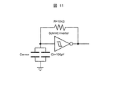
- the force sensors 72A to 72C of the present invention are incorporated in the finger portions 71A to 71C of the end effector 71, they are relatively small. Since the capacitance is proportional to the area of the electrode plate according to the equation (8), it is very small. In order to measure this minute change in capacitance, the oscillation system shown in FIG. 11 is constructed by using the four capacitors of the force sensor 72A (72B, 72C) and the Schmitt trigger inverter, and the pulses are counted at a certain time. Thus, the change in capacitance is obtained as the change in oscillation frequency.
- C sensor is the capacitance of the capacitor of the force sensor 72A (72B, 72C)
- ⁇ is the oscillation constant by the Schmitt trigger inverter
- R is the resistance
- f is the oscillation frequency
- C 0 is the oscillation frequency. It represents the capacitance for adjusting to a frequency that is easy to count.
- the load supported by each rubber cylinder can be obtained by obtaining the relational expression between the change in capacitance measured as the oscillation frequency for each electrode (ch) and the load.
- the sum of the loads supported by the respective rubber cylinders becomes the gripping force value, and the position of the center of gravity of the load is obtained by the above equation (11).
- FIG. 12 shows the fixed electrodes (positive electrode) actually manufactured (FIG. 12A showing the lower surface of the sensor) PE1 to PE4 and the movable electrodes (negative electrode) (FIG. 12B showing the upper surface of the sensor) NE.
- a rubber cylinder for each electrode was formed by a 3D printer using a rubber-like material having a Shore hardness of 27.
- a silicone-based adhesive was used for bonding each member. The longer the path (wiring) for transmitting a pulse between the oscillation system and the measurement system, the greater the change in resistance value due to external noise, wiring movement, or bending, leading to a reduction in measurement accuracy. For this reason, the measurement system for the oscillation frequency is realized with a small substrate, incorporated in the finger part of the end effector, and the A / D converted value is transmitted to the control layer to prevent noise.
- the force sensors 71A to 71C each have a movable electrode (negative electrode) supported by four rubber cylinders.
- the maximum load concentrated on one rubber cylinder is 300 [g]. Since calibration is performed by applying a load to the center of the sensor, it is placed on the weight in increments of 200 [g] from 0 to 1,200 [g], and the amount of decrease from the initial pulse number (at the time of load 0 [g]) at each load is recorded. To do. The above procedure is repeated 5 times, the average of the reduction amount of the pulse number is obtained, and a graph of the reduction amount of the load-pulse number is plotted. Then, an approximate expression for each of 4ch (4 electrodes) is obtained, and the calibration is completed. As a result of obtaining an approximate expression using a quadratic function, the coefficient of determination R 2 was 0.99979.
- the gripping force value F diff of the difference is fed back, and the gripping with the target gripping force is realized by increasing / decreasing the target angle ⁇ t + 1 next to the angle control.
- This target angle ⁇ t + 1 is expressed as the following equation (14).
- f th1 and f th2 represent threshold values
- ⁇ 1 and ⁇ 2 represent control parameters
- the operator grips the work object together so as to cover the end effector 71 as shown in FIG.
- the control unit 60 of the control unit 50 stores the gripping force measured by the force sensors 72A to 72C corresponding to the finger portions 71A to 71C. This makes it possible to teach an appropriate gripping force for each work target.
- a vertical load is applied to the center of the force sensors 72A to 72C at the nine locations shown in FIG.
- One trial is to place the weight on the load receiving tray, measure the load and the load center of gravity coordinates by the force sensors 72A to 72C, and then remove the weight once for each weight for a total of 6 times.
- five trials are performed in order to evaluate the measurement accuracy with respect to the uniform load, and one trial is performed for each of the other portions.
- the closing operation of the finger portions 71A to 71C of the end effector 71 is started at 5 [s] from the start of the experiment, and the opening operation of the finger is started at 20 [s].
- the gripping force value is recorded up to 25 [s], and the experiment is terminated.
- the shape of the work object was a cylinder used for general gripping evaluation (FIG. 13).
- the gripping force of two patterns of strength and weakness is taught to the work object.
- the work object was a sponge with relatively low rigidity among the daily necessities, and the strength of the gripping force tends to appear in the amount of deformation.
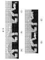
- FIGS. 15B and 16B the work object is gripped by the taught gripping force of two patterns of strength and weakness.
- the amount of movement in the y direction of the center of gravity of the load measured by 71A to 71C is measured. First, a downward force (Downward Force) is applied for 8 seconds, and then an upward force (Upward Force) is applied for 8 seconds. Evaluate by averaging the center of gravity of the load while applying upper and lower forces.
- 18A to 18E show the operation processes of the articulated arms 21 to 24 and the end effector 71 in the robot apparatus 70. It was confirmed that the articulated arms 21 to 24 and the end effector 71 of the robot apparatus 70 can approach and grasp the object while maintaining the specified posture by the trajectory control based on the inverse kinematics.
- FIGS. 19A and 19B show a relationship between values obtained by subtracting the added load from the loads measured by the force sensors 72A to 72C incorporated in the end effector 71.
- FIG. . The circle points are the sample mean of the error, and the upper and lower bars are the standard deviation of the error.
- FIG. 19A shows a measurement error including a non-uniform load
- FIG. 19B shows a measurement error result of the uniform load. From the experimental results, it was confirmed that the developed force sensors 72A to 72C have a measurement accuracy of an error sample average of -0.052 [N] and a standard deviation of 0.088 [N]. Further, regarding the uniform load, the sample average of error was -0.004 [N] and the standard deviation was 0.076 [N].
- Fig. 20 shows the measurement accuracy results of the load center of gravity.
- the error sample average -2.47 [mm] for a load of 0.81 [N] the error sample average -0.03 [mm] for a load of standard deviation 6.38 [mm] and 1.30 [N]
- the standard error of error is 0.12 [mm] for loads with standard deviations of 1.48 [mm] and 1.79 [N]
- the average of errors is -0.05 for loads with standard deviations of 1.63 [mm] and 2.28 [N].
- For a load of [mm], standard deviation 2.37 [mm], 3.77 [N], error sample average -0.14 [mm], for standard deviation 1.14 [mm], 3.26 [N] The sample average was -0.0 [mm], and the standard deviation was 1.6 [mm].
- FIG. 21 shows gripping force values measured by the force sensors 72A to 72C incorporated in the end effector 71.
- the closing operation of the finger portions 71A to 71C of the end effector 71 is started.
- the end effector 71 and the work object contacted and the gripping force increased.
- the target gripping force is followed, and the gripping force decreases with the opening operation of the finger when 20 [s] has elapsed.
- the gripping force value between 15 [s] and 20 [s] with respect to the target gripping force 1.47 [N] is an average of 1.489 [N], an error sample average of 0.019 [N], and a standard deviation of 0.050 [N].
- ⁇ Met Together with the measurement accuracy of the force sensors 72A to 72C, the accuracy of gripping force control as a whole system was 0.033 [N] for the error sample average and 0.138 [N] for the standard deviation.
- the position in the y direction of the load center of gravity during the test is shown in FIG.
- the average y position before applying force was -3.1 [mm].
- the average position in the y direction when applying a downward force was -7.0 [mm], and the average position in the y direction when applying an upward force was 2.6 [mm].
- the articulated arms 21 to 24 and the end effector 71 can be approached and grasped while maintaining the specified posture, so that the articulated arm 21 based on inverse kinematics can be used. It was confirmed that the control of the positions and postures of ⁇ 24 and the end effector 71 was realized. As a result, it can be seen that the robot apparatus 70 capable of control at an arbitrary position and posture in the work environment has been realized.
- the robot device 70 when the robot device 70 grips the work object by the end effector 71, the robot device 70 calculates the position of the load gravity center to each of the force sensors 72A to 72C based on the friction coefficient of the surface of each of the finger portions 71A to 71C.
- the robot device 70 calculates the position of the load gravity center to each of the force sensors 72A to 72C based on the friction coefficient of the surface of each of the finger portions 71A to 71C.
- the load applied to the fingertips of the finger portions 71A to 71C according to the position and orientation of the articulated arms 21 to 24 based on the detection result. Even if it is not uniform, the gripping force by the end effector 71 can be maintained in an appropriate range.
- the work object to be grasped by the end effector 71 based on the imaging results of the vicinity and proximity of the end effector 71 by the imaging unit (one or both of the imaging unit 30 and the imaging camera 32). May be recognized by the control unit (gripping target recognition unit) 60.
- the control unit 60 detects the detection results of the force sensors 72A to 72C corresponding to the pressing forces of the fingers 71A to 71C of the end effector 17. And teaching target data generated by associating the gripping target recognition result with each other and stored in the storage unit 63, and then corresponding to a work target that is the same as or similar to the work target imaged by the imaging unit The related data is read from the storage unit 63, and the gripping force of the end effector 71 is controlled based on the teaching related data.
- the robot apparatus 70 can cause the end effector 71 to perform a gripping operation with an appropriate gripping force in accordance with the work target, and can acquire a gripping force adjustment skill by teaching from the operator. .
- the end effector 25 (71) attached to the wrist 24 (free end) side of the articulated arms 21 to 24 of the robot apparatus 11 (70) is connected to the 3 as shown in FIG. 1 (FIG. 6).
- the end effector 25 (71) prepares multiple types for every work content, Accordingly, it may be selectively attached to the free ends of the multi-joint arms 21 to 24 in a detachable manner.
- the end effector 25 (71) may have a simple jig configuration, or may be configured to perform an opening operation or a closing operation by actuator driving in conjunction with the operation of the articulated arms 21 to 24 under the control of the control unit 60. Also good.
- the imaging camera 32 of the robot apparatus 11 is mounted on the free end side of the articulated arms 21 to 24 or the end effector 25 , but the present invention is not limited to this.
- the image pickup camera 32 may be separately installed at a location close to the robot apparatus 11, or may be incorporated into glasses or the like by the operator and attached to the head.
- the imaging unit 30 provided in the support unit 20 and the imaging camera 32 provided in at least one of the articulated arms 21 to 24 or the end effector 25 (71) are applied.
- the present invention is not limited to this, and various imaging is possible as long as the surrounding environment including the operator can be imaged at the time of use, such as one or a combination of the imaging unit 30 and the imaging camera 32.
- the means can be widely applied.
- an action pattern classifying unit that classifies the upper limb motion of the operator as a behavior pattern composed of a series of motion sequences corresponding to the work content for each work content, and the surrounding environment for each behavior pattern
- the behavior-related data generation unit that generates the behavior-related data in which the combination with the recognition content of the upper limb motion of the operator is connected in time series
- the control unit 60 in the control unit 50 uses the storage unit 63 as the behavior database.
- the robot device 70 further includes a stimulus applying unit (not shown) that is attached to the operator's desired skin surface and applies an external stimulus to the skin surface.
- a stimulus applying unit (not shown) that is attached to the operator's desired skin surface and applies an external stimulus to the skin surface.
- the operator can grasp the gripping force of the end effector 71 in real time, and can reflect it in his / her upper limb movement. Further, the operator can feedback adjust the gripping operation of the end effector 71 without teaching the gripping operation to the upper limb motion support device.
- the joint state detection circuit 65 is applied as the joint angle detection unit.
- the present invention is not limited thereto, and an angle sensor is incorporated together with an actuator for each joint.
- the joint angle may be directly detected from the detection result of the angle sensor.
- an acceleration sensor gyro sensor
Abstract
操作者の作業効率の向上や作業負担の軽減を大幅に改善することが可能な上肢動作支援装置及び上肢動作支援システムを提案する。 生体信号検出部により取得された生体信号に基づいて、多関節アーム及びエンドエフェクタ(25)を操作者の意思に従って三次元動作させる制御部(50)は、上肢動作認識部(30)による認識内容を参照しながら、操作者の上肢動作に連動して多関節アーム及びエンドエフェクタを協調動作させる。
Description
本発明は、例えば片麻痺者が卓上に載置したロボットアームを健常側の手に協調させながら動作可能な上肢動作支援装置及び上肢動作支援システムに適用して好適なるものである。
片麻痺者が、料理や職業動作などの卓上作業を行う際、両手による協調動作は不可能である。そのため、片手への作業負荷の集中、作業効率やその精度の低下、煩雑な作業ができないといった問題が生じる。これらは、片麻痺者のQOL(Quality of Life)の著しい低下を招き、社会参加の障害となっている。
現在行われている対応策として、リハビリテーションによる機能改善や片麻痺者用の福祉用具の利用などの試みが行われている。しかし、一般的に上肢の麻痺は下肢に比べて回復し難い傾向があり、完全回復は全体の14%、部分回復は25%と報告されている。すなわち全体の約6割の片麻痺者は上肢機能に回復が見られない状態にある。
一方、従来の福祉用具は、作業ごとに異なる用具を使用する必要があるため、生活現場で使用する際は複数の福祉用具を恒常的に携帯する必要がある。また、片麻痺者が福祉用具を利用することで作業の難易度を低下させることはできるが、結果的に全ての作業は非麻痺側で行われるため、作業負荷の集中を取り除くことはできない。このため、生活現場での支援機器としては適切でない。
ここで解決方法として、片麻痺者の動作意思を理解し、健常な上肢と連動した動作支援を行うロボットアームが考えられる。例えば、キッチン内の調理作業支援のロボットアームとして、作業の候補位置や作業確率を求め、待機位置を最小化することにより、時間ロスを低減させるものが提案されている(特許文献1参照)。
また食器の配膳や下膳を支援するロボットシステムとして、記録情報に基づき視覚センサを用いながら配膳支援を行うものが提案されている(特許文献2参照)。さらに吊下げ型協調作業ロボットとして、作業対象を撮像しながらロボットアームとの相対位置を認識して、当該相対位置に基づいて作業を行うものが提案されている(特許文献3参照)。
ところが、上述のように様々なロボットアームが開発されているが、例えば卓上スペースでの料理や職業動作における食材のカットや物の組み立て作業について、片麻痺者が健常側の手と協調動作をさせる上で、同じ環境において動作する必要がある。したがって、片麻痺者が使用するロボットアームは非麻痺側の作業領域を狭めることなく、かつ持ち運びが可能なように小型軽量である必要がある。しかしながら、本人の意思に従って実用上十分に耐えうるシステムは、現状では見当たらない。
また片麻痺者のみならず、健常者にとっても卓上作業におけるロボットアームとの協調作業ができることが望ましい。さらには操作者の意思推定を行うとともに、学習効果ももたせることができれば、操作者に特化した専用のロボットアームを実現することが期待される。
本発明は以上の点を考慮してなされたもので、操作者の作業効率の向上や作業負担の軽減を大幅に改善することが可能な上肢動作支援装置及び上肢動作支援システムを提案しようとするものである。
かかる課題を解決するために本発明においては、卓上に載置され、操作者の上肢動作を支援する上肢動作支援装置において、卓上に着脱自在に固定保持され、装置本体を支持する支持部と、支持部に固定端側が連結され、自由端側にエンドエフェクタが接続された多自由度を有する多関節アームと、支持部に設けられ、操作者の周辺環境を撮像する環境撮像部と、環境撮像部により撮像された周辺環境内に含まれる操作者の上肢動作を認識する上肢動作認識部と、操作者の上肢動作に伴って発生する生体信号としての電位を検出する生体信号検出部と、生体信号検出部により取得された生体信号に基づいて、多関節アーム及びエンドエフェクタを操作者の意思に従って三次元動作させる制御部とを備え、制御部は、上肢動作認識部による認識内容を参照しながら、操作者の上肢動作に連動して多関節アーム及びエンドエフェクタを協調動作させるようにした。
この結果、上肢動作支援装置は、操作者の意思に従うとともに当該操作者の健常側の手とを協調して多関節アーム及びエンドエフェクタを動作させることができる。
また本発明においては、操作者の上肢動作を、作業内容ごとに当該作業内容に応じた一連の動作の時間列からなる行動パターンとして分類する行動パターン分類部と、行動パターン分類部により分類された各行動パターンについて、環境撮像部により撮像された周辺環境と、上肢動作認識部による操作者の上肢動作の認識内容との組合せを時系列的に繋げた行動関連データを生成する行動関連データ生成部とを備え、制御部は、行動関連データ生成部から得られた行動関連データに基づいて、操作者の動作意思を推定しながら、多関節アーム及びエンドエフェクタを制御調整するようにした。
この結果、上肢動作支援装置は、操作者の上肢動作から現在の作業内容を特定して、その作業内容に応じた行動パターンと同一又は近似する行動パターンを操作者の動作意思として推定しながら多関節アーム及びエンドエフェクタの動作を調整することができる。
さらに本発明においては、多関節アームの自由端側又はエンドエフェクタに設けられ、環境撮像部の撮像結果に基づいて、操作者の顔を撮影する顔撮像部と、顔撮像部による撮像結果から操作者の顔認識処理を実行すると同時に、当該操作者の視線を検出する視線検出部とを備え、制御部は、所望の切替タイミングで顔撮像部が操作者の顔と当該操作者の視線の延長先とを交互に撮像するように多関節アーム及びエンドエフェクタを適宜制御しながら、操作者の上肢動作に連動して多関節アーム及びエンドエフェクタを協調動作させるようにした。
この結果、上肢動作支援装置は、操作者の視線の延長先にある対象物をリアルタイムで認識しながら、操作者の意思に従うとともに当該操作者の健常側の手との協調して多関節アーム及びエンドエフェクタを動作させることができる。
さらに本発明においては、操作者の上肢動作を、作業内容ごとに当該作業内容に応じた一連の動作の時間列からなる行動パターンとして分類する行動パターン分類部と、行動パターン分類部により分類された各行動パターンについて、環境撮像部により撮像された周辺環境と、上肢動作認識部による操作者の上肢動作の認識内容と、視線検出部による操作者の視線の移動履歴との組合せを時系列的に繋げた行動関連データを生成する行動関連データ生成部とをさらに備え、制御部は、行動関連データ生成部から得られた行動関連データに基づいて、操作者の動作意思を推定しながら、多関節アーム及びエンドエフェクタを制御調整するようにした。
この結果、上肢動作支援装置は、操作者の上肢動作及び視線の延長先の対象物から現在の作業内容を特定して、その作業内容に応じた行動パターンと同一又は近似する行動パターンを操作者の動作意思として推定しながら多関節アーム及びエンドエフェクタの動作を調整することができる。
さらに本発明においては、操作者の周辺環境の音声を集音する集音部と、集音部により集音された操作者の発話内容を解析する言語解析部とを備え、制御部は、言語解析部により解析された操作者の発話内容に基づいて、当該発話内容に応じた動作内容にて多関節アーム及びエンドエフェクタを協調動作させるようにした。
この結果、上肢動作支援装置は、操作者の発話内容に応じた動作内容をリアルタイムで認識しながら、操作者の意思に従うとともに当該操作者の健常側の手との協調して多関節アーム及びエンドエフェクタを動作させることができる。
さらに本発明においては、操作者の上肢動作を、作業内容ごとに当該作業内容に応じた一連の動作の時間列からなる行動パターンとして分類する行動パターン分類部と、行動パターン分類部により分類された各行動パターンについて、環境撮像部により撮像された周辺環境と、上肢動作認識部による操作者の上肢動作の認識内容と、言語解析部による当該操作者の発話内容との組合せを時系列的に繋げた行動関連データを生成する行動関連データ生成部とをさらに備え、制御部は、行動関連データ生成部から得られた行動関連データに基づいて、操作者の動作意思を推定しながら、多関節アーム及びエンドエフェクタを制御調整するようにした。
この結果、上肢動作支援装置は、操作者の上肢動作及び発話内容から現在の作業内容を特定して、その作業内容に応じた行動パターンと同一又は近似する行動パターンを操作者の動作意思として推定しながら多関節アーム及びエンドエフェクタの動作を調整することができる。
さらに本発明においては、行動関連データ生成部は、視線検出部による操作者の視線の移動履歴を組合せに加えて時系列的に繋げて行動関連データを生成するようにした。この結果、上肢動作支援装置は、操作者の上肢動作、発話内容及び視線の延長先の対象物から現在の作業内容を特定して、その作業内容に応じた行動パターンと同一又は近似する行動パターンを操作者の動作意思として推定しながら多関節アーム及びエンドエフェクタの動作を調整することができる。
さらに本発明においては、エンドエフェクタは、指先が互いに近接又は離反する方向に移動可能な少なくとも2本以上の指部と、各指部の指先にそれぞれ設けられ、当該指先に接触する作業対象物への押圧力を検出する力センサとを有し、多関節アームは、多自由度を担保する関節ごとにそれぞれ関節角度を検出する関節角度検出部を有し、制御部は、エンドエフェクタにより作業対象物を把持する際、各指部に対応する力センサの検出結果と、各関節に対応する関節角度検出部の検出結果とに基づいて、エンドエフェクタによる把持力を所望の目標把持力となるように制御するとともに、多関節アームの位置姿勢に応じて各指部の指先に加わる荷重が不均一であっても、エンドエフェクタによる把持力を適正な範囲に維持するようにした。
この結果、上肢動作支援装置は、指定された姿勢を維持しながら、作業対象物へのアプローチ及び把持を行うことが可能となり、作業環境における任意の位置や姿勢での動作制御を実現できる。
さらに本発明においては、制御部は、エンドエフェクタにより作業対象物を把持する際、各指部の表面の摩擦係数に基づき、各力センサへの荷重重心の位置を算出した後、当該荷重重心の移動に基づいて、作業対象物に対する外力を検出するようにした。
この結果、上肢動作支援装置は、作業対象物に対する操作者の働きかけを含めた外力に基づいて、エンドエフェクタに不均一荷重が加わった場合でも正確に把持力を計測することが可能となる。さらに剛性の異なる作業対象物を適切な把持力で扱うことが可能となる。
さらに本発明においては、撮像部によるエンドエフェクタの近傍及び近接対象の撮像結果から、当該エンドエフェクタによる把持対象となる作業対象物を認識する把持対象認識部と、操作者によってエンドエフェクタによる作業対象物の把持動作が教示されたとき、当該エンドエフェクタの各指部の押圧力に対応する力センサの検出結果と、把持対象認識部による認識結果とを関連付けて教示関連データを生成する教示関連データ生成部とを備え、制御部は、撮像部により撮像された作業対象物と同一又は近似する作業対象物に対応する教示関連データを教示関連データ生成部から読み出して、当該教示関連データに基づいてエンドエフェクタの把持力を制御するようにした。
この結果、上肢動作支援装置は、把持動作が教示された作業対象物と同一又は近似する作業対象物を認識した際、記憶された適正な把持力にて当該作業対象物を把持することが可能となる。
さらに本発明においては、操作者の上肢動作を、作業内容ごとに当該作業内容に応じた一連の動作の時間列からなる行動パターンとして分類する行動パターン分類部と、行動パターン分類部により分類された各行動パターンについて、撮像部により撮像された周辺環境と、上肢動作認識部による操作者の上肢動作の認識内容と、教示関連データ生成部により生成された教示関連データとの組合せを時系列的に繋げた行動関連データを生成する行動関連データ生成部とを備え、制御部は、行動関連データ生成部から得られた行動関連データに基づいて、操作者の動作意思を推定しながら、多関節アーム及びエンドエフェクタを制御調整するようにした。
この結果、上肢動作支援装置は、操作者の上肢動作及び作業対象物への把持動作から現在の作業内容を特定して、その作業内容に応じた行動パターンと同一又は近似する行動パターンを操作者の動作意思として推定しながら多関節アーム及びエンドエフェクタの動作を調整することができる。
さらに本発明においては、操作者の所望の皮膚表面に取り付けられ、当該皮膚表面に対して外部刺激を付与する刺激付与部をさらに備え、制御部は、エンドエフェクタにより作業対象物を把持する際、各指部に対応する力センサの検出結果に基づいて、エンドエフェクタによる把持力に応じたパターン及び強度の外部刺激を刺激付与部により操作者に付与するようにした。
この結果、操作者は、エンドエフェクタの把持力をリアルタイムで把握することができ、自己の上肢動作に反映させることが可能となる。さらに操作者は、上肢動作支援装置に対して把持動作を教示しなくても、エンドエフェクタの把持動作をフィードバック調整することも可能となる。
さらに本発明においては、エンドエフェクタは、作業内容ごとに複数の種類が用意され、当該作業内容に応じて選択的に多関節アームの自由端側に対して着脱自在に取り付け可能である。
さらに本発明においては、上肢動作支援装置と、当該上肢動作支援装置に設けられ、行動関連データ生成部から各行動パターンごとに得られた行動関連データと、当該行動関連データに対応する多関節アーム及びエンドエフェクタの制御調整結果を表す制御調整データとを送信する通信部と、上肢動作支援装置と別体に設けられ、通信部から送信される行動関連データ及び制御調整データを通信回線を介して受信してデータベース化して管理サーバに格納するデータ端末装置とを備えるようにした。
この結果、上肢動作支援システムは、作業内容に応じた行動パターンについての操作者の上肢動作内容及び周辺環境と、これらに対応する多関節アーム及びエンドエフェクタの制御調整結果とを管理サーバに格納しておくことができる。
さらに本発明においては、データ端末装置は、管理サーバに格納されている行動関連データ及び制御調整データのデータ群について、各行動パターンごとに当該行動パターンと同一又は近似する行動パターンを表す行動関連データ及び制御調整データを順次更新するようにした。
この結果、上肢動作支援システムは、管理サーバには特定の作業内容について、作業者が何度も同様の行動パターンを繰り返した場合、その行動パターンを順次更新して格納しておくことにより、操作者固有のデータ群として蓄積することができる。
さらに本発明においては、上肢動作支援装置の制御部は、現在の作業内容に応じた行動パターンを表す行動関連データ及び制御調整データを通信部を介してデータ端末装置に送信した際、データ端末装置は、管理サーバに格納されている行動関連データ及び制御調整データのデータ群の中から、当該作業内容に応じた行動パターンと同一又は近似する行動パターンを表す行動関連データ及び制御調整データを読み出して、上肢動作支援装置の通信部を介して制御部に送信するようにした。
この結果、上肢動作支援システムは、管理サーバから作業内容に応じた行動パターンに最も近い行動パターンについての操作者固有のデータ群を読み出すことができ、操作者の上肢動作に最適な協調動作を多関節アーム及びエンドエフェクタに動作させることが可能となる。
本発明によれば、操作者の上肢動作を認識しながら、当該上肢動作に連動して多関節アーム及びエンドエフェクタを協調動作させるようにして、操作者の作業効率の向上や作業負担の軽減を大幅に改善可能な上肢動作支援装置及び上肢動作支援システムを実現することができる。
以下図面について、本発明の一実施の形態を詳述する。
(1)ロボットシステムの構成
図1は本実施の形態によるロボットシステム(上肢動作支援システム)10を示し、垂直多関節型のロボット装置(上肢動作支援装置)11と、当該ロボット装置11との間で通信回線12を介して双方向に各種のデータを送受信するデータ端末装置13及び管理サーバ14とからなる。
図1は本実施の形態によるロボットシステム(上肢動作支援システム)10を示し、垂直多関節型のロボット装置(上肢動作支援装置)11と、当該ロボット装置11との間で通信回線12を介して双方向に各種のデータを送受信するデータ端末装置13及び管理サーバ14とからなる。
ロボット装置11は、卓上に着脱自在に載置可能な支持部20と、当該支持部20に水平方向に旋回可能に連結された肩部21と、当該肩部21に上下方向に旋回可能に連結された下腕部22と、当該下腕部22に上下方向に旋回可能に連結された上腕部23と、当該上腕部23に上下方向に旋回可能かつ捻り回転可能に連結された手首部24と、当該手首部24に捻り回転可能に連結されたエンドエフェクタ25とを有する。
すなわちロボット装置11は、支持部20に対して6自由度をもつ多関節アーム(肩部21、下腕部22、上腕部23、手首部24)が各軸(A軸~F軸)を回転中心として回動自在に連結され、当該多関節アーム21~24の先端にエンドエフェクタ25が取り付けられた構成からなる。
具体的には、支持部20と肩部21はA軸を中心に回動可能に連結され、肩部21と下腕部22はB軸を中心に回動可能に連結され、下腕部22と上腕部23はC軸を中心に回動可能に連結され、上腕部23と手首部24はD軸を中心に回動可能に連結され、手首部24自体はE軸を中心に回動可能であり、当該手首部24はエンドエフェクタ25との間でF軸を中心に回動可能に連結されている。
これら支持部20と肩部21の関節部位、肩部21と下腕部22の関節部位、下腕部22と上腕部23の関節部位、上腕部23と手首部24の関節部位、手首部24自体の関節部位、手首部24とエンドエフェクタ25の関節部位にはそれぞれ例えば直流サーボモータからなるアクチュエータMA~MF(後述する図3)が設けられ、図示しない伝達機構を介して回転駆動されるようになされている。
このエンドエフェクタ25は、操作者の作業内容ごとに複数の種類が用意されており、当該作業内容に応じて選択的に手首部24に対して着脱自在に取り付けることができるとともに、内部にアクチュエータMG(後述する図3)を有する場合は多関節アーム21~24とともに駆動制御されるようになされている。例えば3本指の把持機能を有するエンドエフェクタ25は、多関節アーム21~24の動作に連動したアクチュエータ駆動により開動作又は閉動作を行うようになされている。
また支持部20には、制御ユニット50が電気的に接続されるとともに、外側表面の所定部位に操作者の周辺環境を撮影するための撮像ユニット30が設けられ、さらに周辺環境の音声を集音するための集音マイク31が設けられている。なお撮像ユニット30及び集音マイク31は、多関節アーム21~24の肩部21に設けるようにしても良い。
この撮像ユニット(環境撮像部)30は、レーザレンジセンサ、RGB-Dセンサ及び3D距離画像センサからなり、操作者の健常側の手や腕の動作を監視するようになされている。
レーザレンジセンサは、設置位置から見た対象物に照射し、その反射光を受光して距離を算出する。これを一定角度間隔で距離を測定することにより、平面上に扇状の距離情報を最大30m、角度240度の範囲で得ることができる。
RGB-Dセンサは、RGBカラーカメラ機能に加えて、当該カメラから見た対象物までの距離を計測できる深度センサを有し、対象物の3次元スキャンを行うことができる。この深度センサは赤外線センサからなり、構造化光の単一のパターンを対象物に投影した状態で対象を撮影し、そのパラメータを用いて三角測量により画像上の各点のデプスを算出する。
例えばRGB-Dセンサとして、例えばKinect(マイクロソフト社の商標名)を適用した場合、水平視野57度、垂直視野43度、センサ範囲は1.2m~3.5mの範囲を撮影することが可能であり、RGB画像は640×480、Depth(深度)画像は320×240画素で共に30フレーム/秒で取得できる。
3D距離画像センサは、LEDパルスを照射し、対象物からの反射光の到達時間を画素単位で計測すると同時に取得した画像情報を重畳することにより、対象物までの距離情報を画素単位で算出する。この3D距離画像センサは、上述のRGB-Dセンサよりも高精度の検出能力を有し、かつレーザレンジセンサよりも視野角が広いことから、補完センサとして有用である。3D距離画像センサとして、例えばピクセルソレイユ(日本信号株式会社の商品名)を適用した場合、水平視野72度、垂直視野72度、センサ範囲は0.3m~4.0mの範囲を撮影することが可能である。
さらにエンドエフェクタ25又は多関節アーム21~24の手首部24には、撮像カメラ32が搭載されており、多関節アーム21~24の動作に応じて所望の位置で撮影し得るようになされている。
ロボット装置11は、支持部20が卓上に着脱自在に載置可能であることから、図2に示すように、操作者がテーブルを前に椅子に着座した状態にて、当該テーブル上の所望位置にロボット装置11を載置して使用することができる。特に操作者が片麻痺者である場合には、健常側の腕と反対側のテーブル上に載置すれば、片麻痺側の腕の代わりにロボット装置11を協調動作させることが可能となる。
(2)ロボット装置における制御ユニットのシステム構成
図3に示すように、制御ユニット50は、ロボット装置11全体の制御を司る制御部(CPU:Central Processing Unit)60と、操作者の上肢動作に伴って発生する生体信号としての電位を検出する生体信号検出部61と、ロボット装置11の多関節アーム21~24の各関節のアクチュエータMA~MDを駆動する駆動回路62と、ロボット装置全体のシステムプログラム等が記憶された記憶部63と、外部のデータ端末装置13との通信を行う通信部64とを有する。
図3に示すように、制御ユニット50は、ロボット装置11全体の制御を司る制御部(CPU:Central Processing Unit)60と、操作者の上肢動作に伴って発生する生体信号としての電位を検出する生体信号検出部61と、ロボット装置11の多関節アーム21~24の各関節のアクチュエータMA~MDを駆動する駆動回路62と、ロボット装置全体のシステムプログラム等が記憶された記憶部63と、外部のデータ端末装置13との通信を行う通信部64とを有する。
生体信号検出部61は、操作者の健常側の上腕及び前腕の体表面に配置され、操作者の脳から当該上腕及び前腕に伝達された神経伝達信号を生体信号として検出し、制御ユニット50の制御部60に送信する。制御部60は、生体信号検出部61により出力された生体信号に基づいて、操作者の意思に従った上肢を動作させる動力を駆動回路62を通じて多関節アーム21~24の各関節のアクチュエータMA~MF(必要に応じてエンドエフェクタ25のアクチュエータMGも含む。以下同じ。)にそれぞれ発生させる。
これにより制御部60は、生体信号検出部61により取得された生体信号に基づいて、多関節アーム21~24及びエンドエフェクタ25を操作者の意思に従って三次元動作させることができる。
また制御ユニット50は、多関節アーム21~24の各関節の状態を検出するための関節状態検出回路65を有し、当該各関節のアクチュエータMA~MGに設けられたロータリエンコーダRA~RGからのパルス信号に基づいて、当該各アクチュエータMA~MGの回転角度を検出するとともに、単位時間当たりの当該パルス信号数に基づいて各アクチュエータMA~MGの回転速度を検出する。
関節状態検出回路65により検出された各アクチュエータMA~MGの回転角度及び回転速度は、制御部60及び駆動回路62にともに供給される。
制御部60には、生体信号検出部61からの生体信号と、通信部64を介して外部のデータ端末装置13から送信される行動指令データや行動学習データ等とに基づいて、多関節アーム21~24及びエンドエフェクタ25の各関節のアクチュエータMA~MGに対する駆動指令値を生成する。
駆動回路62は、制御部60から与えられる各アクチュエータMA~MGへの駆動指令値と関節状態検出部65から与えられる回転角度及回転速度とを比較し、その偏差に応じた電流をそれぞれ対応するアクチュエータMA~MGに供給する。
これにより、制御部60は、多関節アーム21~24及びエンドエフェクタ25を操作者の意思に従うように三次元動作させることができる。
さらに制御部60は、ロボット装置11の支持部20に設けられた撮像ユニット30からの出力に基づいて、周辺環境内に含まれる操作者の上肢動作を認識するとともに、その認識内容を参照しながら、操作者の上肢動作に連動して多関節アーム21~24及びエンドエフェクタ25を協調動作させるようになされている。
これに加えて、制御部60は、撮像ユニット(撮像部)30の撮像結果に基づいて、操作者の顔を含む上半身の位置を推定し、多関節アーム21~24の手首部24又はエンドエフェクタ25を三次元動作させながら、撮像カメラ(顔撮像部)32を用いて当該操作者の顔を撮像する。
そして制御部60は、撮像カメラ32の撮像結果から操作者の顔認識処理を実行すると同時に、当該操作者の視線を検出するようになされている。具体的には、例えば特開2007ー265367号公報に開示されているような、顔認識処理及び視線検出方法を適用しても良い。
すなわち顔認識処理としては、撮像画像上に設定画素数の枠からなるサブウィンドウを走査させて複数の部分画像を生成し、このうち顔である該部分画像を所定のパターン認識手法や目鼻等の特徴検出手法を用いて判別する方法が挙げられる。
また視線検出方法としては、撮像した画像全体の中から検出した顔画像の目から複数の目特徴点を抽出するとともに 、顔を構成する部位から複数の顔特徴点を抽出した後、当該複数の目特徴点を用いて目の向きを示す目特徴量を生成するとともに、複数の顔特徴点を用いて顔の向きを示す顔特徴量を生成し、これら目特徴量と顔特徴量とを用いて視線の向きを検出する方法が挙げられる。
このようにして、制御部60は、所望の切替タイミングで撮像カメラ(撮像部)32が操作者の顔と当該操作者の視線の延長先とを交互に撮像するように多関節アーム21~24及びエンドエフェクタ25を適宜制御しながら、操作者の上肢動作に連動して多関節アーム21~24及びエンドエフェクタ25を協調動作させることができる。
さらに制御部60は、集音マイク31を用いて集音した操作者の周辺環境の音声に基づいて、当該操作者の発話内容を言語解析するようになされている。具体的には、例えば特開2010ー197709号公報に開示されているように、単語及び修飾語の組合せまで認識可能な音声認識応答技術を適用しても良い。本発明では、この音声認識応答技術に加えて、音声認識された言語を解析して操作者の発話内容を特定した後、当該発話内容と対応する動作内容を予め記憶部63に記憶しておいた変換テーブルを用いて抽出する。
そして制御部60は、当該言語解析した操作者の発話内容に基づく動作内容を、多関節アーム21~24及びエンドエフェクタ25の協調動作に反映させることができる。
なお、制御ユニット50には、駆動用電源としてのバッテリ66が内蔵されており、多関節アーム21~24の各関節やエンドエフェクタ25のアクチュエータMA~MGや撮像ユニット30、集音マイク31、撮影カメラ32などへの電源供給を行う。
(3)ロボットシステムによる行動実行システムの構築
本実施の形態のロボットシステム10においては、操作者の周辺環境と操作者の上肢動作とに基づいて、操作者による作業内容を一連の動作の時間列として自動的にデータベース化しておき、操作者の現在の状態から目標状態に至る行動を自律的に計画し、多関節アーム21~24及びエンドエフェクタ25を駆動して目的の行動を実現する。
本実施の形態のロボットシステム10においては、操作者の周辺環境と操作者の上肢動作とに基づいて、操作者による作業内容を一連の動作の時間列として自動的にデータベース化しておき、操作者の現在の状態から目標状態に至る行動を自律的に計画し、多関節アーム21~24及びエンドエフェクタ25を駆動して目的の行動を実現する。
実際に人間が行動を行う場合は、多くの場合「肘を曲げる」、「肩を下げる」というような「個々の運動単位」ではなく、「包丁で食材を切る」、「食べ物を口に運ぶ」というような「作業文脈単位」で行動を計画・実行している。
操作者との協調動作を直感的に実行させるロボットシステム10を構築するためには、操作者自らが状況に応じて個々の動作を組み合わせて行動命令を記述して作業を指示するよりも、ロボット装置11が現在の操作者の状況に基づいて、予め教示された動作の中から次に行われる可能性のある動作だけを操作者に作業文脈単位で選択的に提示できることが有効である。
行動の中にある個々の動作(例えば「肘を曲げる」、「肩を下げる」など)を「ベースレベル」と定義し、それらの動作を組み合わせた作業文脈の単位(例えば「食べ物を口に運ぶ」など)を「メタレベル」の行動と定義する。
メタレベルの行動を獲得するためには、操作者自身の状態のみならず、その周囲の環境情報の把握も同時に行うことが必要である。環境情報を把握することにより、操作者が現在置かれている状況を理解し、作業目標に対して現在の状態からどのように行動すべきかを決定することができるためである。
具体的には、料理作業を行う場合、操作者が包丁を持った持った状態でとる行動は、まな板の上に食材がのっていれば「包丁で切る」行動を提示する一方、まな板の上に何ものっていなければ「(包丁を横に置いてから)食材をまな板の上にのせる」行動を提示する。
本発明においては、環境情報を利用したメタレベルの行動認識として、状況を繋ぐ複数の動作の系列として行動を表現する手法のみならず、学習した行動を組み替えて新しい行動を再合成する手法も加えるようにする。
すなわち、本発明においては、行動を個々の動作に分解し、動作の区切り点における作業環境の状況を状態とすることで作業環境の状態を動作で繋いだ状態遷移図として行動を表現する手法(以下、これを「StateMap」という)を用いる。
この手法により行動間の時系列的な情報のつながりは失われるものの、それゆえ動作の因果関係に基づいた、学習したことがない行動をも自動的にデータベースに獲得することが可能になり、利用者の入力の負担を最小限に抑えられる。
行動をStateMapとして表現する事による利点は、従来のいわば「ベースレベル」の動作を取り扱う動作表現手法に対し、ベースレベルの動作の組み合わせにより構成される「作業文脈(メタレベル)」つまり直感的な目的単位で行動を取り扱うことが可能になることである。
このようにロボットシステム10においては、操作者の周辺環境と操作者の上肢動作の認識内容とを状態とした状態遷移図(StateMap)を用いて、基礎的な動作からなる料理作業(包丁による食材のカット作業)を、目的を提示するだけで自律的に実行する行動実行システムを実現する。
この行動実行システムは、「認識系」、「獲得系」、「生成系」の3つの部位によって実現される。認識系では、撮像内容から周辺環境を含む操作者の一連の行動を動作の区切り点における状態で分解し、視覚面から行動を認識する。獲得系では、行動を自動的に統合したStateMapとして表現し獲得する。生成系では、作成したStateMapの状態を適切に組み直して与えられた作業行動を生成する。
(3-1)「StateMap」を用いた行動のメタレベル表現手法
環境と行動を同時に認識し、行動をロボット装置11に実現可能な動作の系列に分解する。認識した動作の切り替わり点における操作者と周辺環境の位置座標情報を「状態」とする。操作者と周辺環境の状況は動作によって関係付けられ、行動はある状況から別の状況へと変化させて行く動作の系列として表現される。
環境と行動を同時に認識し、行動をロボット装置11に実現可能な動作の系列に分解する。認識した動作の切り替わり点における操作者と周辺環境の位置座標情報を「状態」とする。操作者と周辺環境の状況は動作によって関係付けられ、行動はある状況から別の状況へと変化させて行く動作の系列として表現される。
この結果、別々の状況における異なる目的の行動は、動作情報だけから同じと判断されることなく、意味の異なる行動として表現できる。例えば「ボタンを押す」動作に対して、一方は「エレベータの操作」行動であり、他方は「商品を購入する」行動として区別される。
行動は動作の切り替わり点で区切られているため、個々の動作の逆動作を生成することで容易に逆に向かう行動を生成することが可能である。これによって、少ない情報からでも多くの動作を獲得でき、より柔軟に行動を生成できる。
認識したすべての行動とその逆行動は同一の状態をまとめ、一つの有向グラフの形に統合して表現する。これにより、学習した行動は、時系列情報を消失し、動作と環境の因果関係を表す状態遷移図としてメタレベルで表現できる。
このような表現を用いることで、学習した行動の再現だけでなく、学習経験を利用し、新しい行動を生成することも可能となる。複数の人間、環境で作成されたStateMapは、共通する状態をまとめることで統合できる。これにより行動の要素が増加し、より柔軟に行動を生成できる。
StateMapを利用することによりロボット装置11に実現させたい状態を提示すれば、現在の状態から所望の状態までの最短動作経路を探索し、分解された複数の動作を再合成して一連の行動を生成できる。またこのとき教示した作業の組み合わせとしての新たな作業についても学習した行動を応用して実現できる。
(3-2)認識系の実現方法
ロボットシステム10において、操作者の上肢動作と周辺環境と撮像ユニット30の撮像結果から同時に認識する視覚認識方法について説明する。
ロボットシステム10において、操作者の上肢動作と周辺環境と撮像ユニット30の撮像結果から同時に認識する視覚認識方法について説明する。
制御ユニット50内の制御部60は、撮像ユニット(レーザレンジセンサ、RGB-Dセンサ及び3D距離画像センサ)30の撮像結果から、動画像における撮像範囲の中から背景画像を抽出する。すなわち数フレーム分の撮影画像の平均値から背景画像か否かを判断する。その際、当該平均値より高い値の平均と低い値の平均を算出し、時間の長い方の平均を背景値とする(図4(A))。
続いて制御部60は、動画像の中から色差を利用して動体を抽出する。輝度差ではなく、RGBの値の差(色差)を利用したのは、色の違いの方が輝度差に対してより多くの情報を利用できるからである。さらに照明や日光による輝度変化の影響を受けにくいため、一連の作業を連続的に認識する際に輝度変化に対して強いという利点もある。
色差h(t)(0≦h(t)≦255)は、次式(1)のように表される。

ここで、L(t)とその平均値は、それぞれ次式(2)及び(3)にて表される。


色差h(t)(0≦h(t)≦255)は、次式(1)のように表される。
そして制御部60は、動画像の中から抽出した動体領域の面重心を求め、その軌跡を操作者の運動軌跡として検出する。これは操作者が同時に2人以上現れない場合を考慮したものである。
その後、制御部60は、撮像領域から物体領域のレイヤーを分離して当該物体の位置を検出する。すなわち、撮像領域内に物体が置かれたとき、次式(4)に示す分離フィルタ演算を実施することによって物体の領域を分離して位置を検出する(図4(B))。

また物体が動かされたとき、分離されていた物体の領域は、次式(5)に示す結合フィルタ演算によって動体の領域に結合される(図4(C))。

なお、上述の式(4)及び(5)において、φ(k)out、φ(k)inが1以上のとき、各フィルタは有効となり、物体領域の分離、結合が行われる。
続いて制御部60は、運動軌跡と物体位置変化から操作者の上肢動作を判別する。すなわちロボット装置11に実現可能な動作を元に操作者の上肢動作を分解する。具体的には制御部60は、Open HRP(Open Architecture Humanoid Robotics Platform)シミュレータを用いてロボット装置11の多関節アーム21~24及びエンドエフェクタ25に実現可能な基本動作に置き換えて認識させる。
すなわち制御部60は、一定期間分の重心軌道を抽出して、その重心軌道の開始時の座標と終了時の座標とを保存しておく。そして終了時の座標と開始時の座標についてXY平面にて所定の閾値との大小を比較することにより基本動作を認識する。そして認識した基本動作が連続性を考慮して基本動作の組み合わせ部分を置き換える。このように制御部60は、一定時間抽出した物体の面重心軌道の間の軌道波形について条件分岐によって基本動作を判別することが可能となる。
このようにして制御部60は、上述の視覚認識方法を用いて、操作者の上肢動作及び周辺環境の認識を行うことにより、操作者の上肢動作及び周辺環境内の物体の座標をほぼ正確に認識することが可能となる。
実験結果によれば、図5(A)のようにテーブル上に2つのカップが載置されている様子を撮像しておき、上述の視覚認識方法によれば、図5(B)にて物体(カップ)ごとにレイヤーを分離して認識した後、合成すれば、図5(C)のように、2つのカップの位置を自動的に認識することができた。
(3-3)獲得系の実現方法
次に制御部60は、認識した操作者の上肢動作と環境情報から行動をStateMapとして自動的に記述する。これによって時系列上の複数の行動がどのように関係付けられ、どのような行程を踏んでいるのか、つまり行動の意味付けが自動的に行われる。また、StateMapとして記述することで、新しい行動の自動生成が可能となる。
次に制御部60は、認識した操作者の上肢動作と環境情報から行動をStateMapとして自動的に記述する。これによって時系列上の複数の行動がどのように関係付けられ、どのような行程を踏んでいるのか、つまり行動の意味付けが自動的に行われる。また、StateMapとして記述することで、新しい行動の自動生成が可能となる。
まず制御部60は、視覚認識方法によって認識した動作の切り替わり点における操作者の健常側の手や腕と周辺環境内の物体との位置座標情報を状態として生成する。この位置座標は、撮像ユニットから得られた映像の2次元座標情報である。
行動を動作と動作による環境状態の遷移として表現すると、制御部60は、個々の動作の逆動作を作成して連結することにより、逆向きの行動を生成することができる。具体的には制御部60は、Open HRPシミュレータを用いてロボット装置11の多関節アーム21~24及びエンドエフェクタ25に実現可能な基本動作について、所定の対応表に従い逆動作を作成する。
状態を構成する操作者の上肢や周辺環境内の物体の座標がほぼ同一の場合は、同一の状態としてまとめられ、2つの行動は統合することができる。このような行動の統合によってStateMapが自動的に作成される。このStateMapは、図示しないが、状態のリスト構造と、状態の接続番号に対応する動作の内容を記述した行動データベースによって構成される。
(3-4)生成系の実現方法
制御部60は、操作者の意思である目標状態が入力されると、現在の状態を基準にStateMapから過去に経験した状況とマッチングをとり、その状態を結ぶ経路を探索し、行動を生成する。このように制御部60は、StateMapを利用することにより、多関節アーム21~24及びエンドエフェクタ25に実現して欲しい状況について、現在の状態からの最短動作経路を探索し、複数の動作の並びとして一連の行動を獲得できる。またこのとき、教示した作業の組み合わせとしての新たな作業についても学習した行動を応用して実現できる。
制御部60は、操作者の意思である目標状態が入力されると、現在の状態を基準にStateMapから過去に経験した状況とマッチングをとり、その状態を結ぶ経路を探索し、行動を生成する。このように制御部60は、StateMapを利用することにより、多関節アーム21~24及びエンドエフェクタ25に実現して欲しい状況について、現在の状態からの最短動作経路を探索し、複数の動作の並びとして一連の行動を獲得できる。またこのとき、教示した作業の組み合わせとしての新たな作業についても学習した行動を応用して実現できる。
なお、行動は人と物体の二次元座標を引数として持つ動作命令の系列として生成されており、これを三次元のシミュレータ(Open HRP)においてロボット装置11に命令として与えるために、系の変換が行われるようになされている。例えば、操作者の上肢を上げ下げする動作については、動作前後の腕の重心の高さをテーブル上からの高さとして与えたり、物体の載置や離脱については、物体を認識した座標からテーブル上の置く場所の位置を判別したりする。
(3-5)「StateMap」による行動データベースを用いた行動の自動再生方法
制御部60は、上述したStateMapで表現された行動データベースを用いることにより、操作者の次の行動を予測提示し、目的の行動を選択させることが可能となる。StateMapには既に自動的に前後の関係と関連付けてデータベース化されているため、制御部60は、次に実現したい状態を選択すれば、行動手順を把握して途中の動作を自動生成しながら行動を再現することができる。
制御部60は、上述したStateMapで表現された行動データベースを用いることにより、操作者の次の行動を予測提示し、目的の行動を選択させることが可能となる。StateMapには既に自動的に前後の関係と関連付けてデータベース化されているため、制御部60は、次に実現したい状態を選択すれば、行動手順を把握して途中の動作を自動生成しながら行動を再現することができる。
具体的にStateMapによる行動データベースが行動シーケンスの自動生成がどのように実装されるかを説明する。行動データベースには、料理作業において、各状態は手先の3次元空間における位置情報として保存される。
料理作業を開始する場合、「まな板の上に食材(例えば大根)が載置されている状態」から開始し、StateMapを用いた場合、自動的に前後の関係と関連付けてデータベース化されているため、次に実現される状態は、「エンドフェクタが食材を押さえつける状態」、「操作者が食材の位置を調整する状態」、「操作者が包丁を用いてカットし始める状態」のいずれかであると予測できる。
操作者がさらに先の状態を目標として指定した場合はそこにいたる状態遷移のパスを探索し行動を実現できる。例えば「操作者が食材の位置を調整する状態」から「操作者が包丁を用いて食材を全てカットする状態」を目標状態とすると、状態遷移マップの経路検索を行って、「操作者が食材の位置を調整する状態」から「エンドエフェクタ25が食材を押さえつける状態」、「操作者が包丁を用いて食材をカットする状態」、「エンドエフェクタ25が食材を端の方にずらして保持する状態」と順に移動していくように自動的に動作を計画できる。
ある状態から次の状態に進む場合に、特定の行動とこれと異なる行動との2通り存在する場合には、選択が必要な分岐のみを操作者に追加して選択させることが解消できる。
このように上肢動作支援システムは、制御部60は、現在の状態を常に把握しており、StateMapを用いて、今の状態から遷移できる状態だけを探索しながら、目的の状態に至る動作を順次実行することができ、操作者の操作の負担をより軽減した知能的な自律システムが実現できる。
(4)本実施の形態によるロボット装置の動作
本実施の形態において、ロボット装置11を着脱自在に卓上に固定保持しておき、操作者の意思に従って当該操作者の上肢動作に多関節アーム21~24及びエンドエフェクタ25を連動させる際、撮像ユニット(環境撮像部)30により制御部(上肢動作認識部)60は操作者の周辺環境を認識すると同時に当該操作者の上肢動作を認識する。
本実施の形態において、ロボット装置11を着脱自在に卓上に固定保持しておき、操作者の意思に従って当該操作者の上肢動作に多関節アーム21~24及びエンドエフェクタ25を連動させる際、撮像ユニット(環境撮像部)30により制御部(上肢動作認識部)60は操作者の周辺環境を認識すると同時に当該操作者の上肢動作を認識する。
これによりロボット装置11は、現在の作業環境(台所やリビング等)を把握すると同時に操作者による作業内容(料理や食事等)を特定(又は推定)することができる。そしてロボット装置11は、操作者の上肢動作の認識内容を参照しながら、当該上肢動作に連動して多関節アーム21~24及びエンドエフェクタ25を協調動作させる。
この結果、ロボット装置11は、操作者の意思に従うとともに当該操作者の健常側の手とを協調して多関節アーム21~24及びエンドエフェクタ25を動作させることができる。
またロボット装置は、操作者の上肢動作を、作業内容ごとに当該作業内容に応じた一連の動作の時間列からなる行動パターンとして分類しておき、当該分類された各行動パターンについて、撮像ユニットにより撮像した操作者の周辺環境と、当該操作者の上肢動作の認識内容との組合せを時系列的に繋げた行動関連データを生成する。ロボット装置は、行動関連データに基づいて、操作者の動作意思を推定しながら、多関節アーム21~24及びエンドエフェクタ25を制御調整する。
この結果、ロボット装置11は、操作者の上肢動作から現在の作業内容を特定して、その作業内容に応じた行動パターンと同一又は近似する行動パターンを操作者の動作意思として推定しながら多関節アーム21~24及びエンドエフェクタ25の動作を調整することができる。
さらにロボット装置は、多関節アーム21~24の手首部24又はエンドエフェクタ25に設けられた撮像カメラ32を用いて操作者の顔を撮像して、当該撮像結果から制御部(視線検出部)60は顔認識処理を実行すると同時に当該操作者の視線を検出する。
続いてロボット装置11は、所望の切替タイミングで撮像カメラ32が操作者の顔と当該操作者の視線の延長先とを交互に撮像するように多関節アーム21~24及びエンドエフェクタ25を適宜制御しながら、操作者の上肢動作に連動して多関節アーム21~24及びエンドエフェクタ25を協調動作させる。
この結果、ロボット装置11は、操作者の視線の延長先にある対象物をリアルタイムで認識しながら、操作者の意思に従うとともに当該操作者の健常側の手との協調して多関節アーム21~24及びエンドエフェクタ25を動作させることができる。
さらにロボット装置11は、操作者の上肢動作を、作業内容ごとに当該作業内容に応じた一連の動作の時間列からなる行動パターンとして分類しておき、当該分類された各行動パターンについて、撮像ユニット30により撮像した操作者の周辺環境と、当該操作者の上肢動作の認識内容と、操作者の視線の移動履歴との組合せを時系列的に繋げた行動関連データを生成する。
そしてロボット装置11は、行動関連データに基づいて、操作者の動作意思を推定しながら、多関節アーム21~24及びエンドエフェクタ25を制御調整する。この結果、ロボット装置11は、操作者の上肢動作及び視線の延長先の対象物から現在の作業内容を特定して、その作業内容に応じた行動パターンと同一又は近似する行動パターンを操作者の動作意思として推定しながら多関節アーム21~24及びエンドエフェクタ25の動作を調整することができる。
さらにロボット装置11は、集音マイク31を用いて操作者の周辺環境の音声を集音して、当該集音結果から操作者の発話内容を解析した後、当該発話内容に応じた動作内容にて多関節アーム21~24及びエンドエフェクタ25を協調動作させる。この結果、ロボット装置11は、操作者の発話内容に応じた動作内容をリアルタイムで認識しながら、操作者の意思に従うとともに当該操作者の健常側の手との協調して多関節アーム21~24及びエンドエフェクタ25を動作させることができる。
さらにロボット装置11は、操作者の上肢動作を、作業内容ごとに当該作業内容に応じた一連の動作の時間列からなる行動パターンとして分類しておき、分類された各行動パターンについて、環境ユニット30により撮像された周辺環境と、当該操作者の上肢動作の認識内容と、操作者の発話内容との組合せを時系列的に繋げた行動関連データを生成する。
そしてロボット装置11は、行動関連データに基づいて、操作者の動作意思を推定しながら、多関節アーム21~24及びエンドエフェクタ25を制御調整することにより、操作者の上肢動作及び発話内容から現在の作業内容を特定して、その作業内容に応じた行動パターンと同一又は近似する行動パターンを操作者の動作意思として推定しながら多関節アーム21~24及びエンドエフェクタ25の動作を調整することができる。
これに加えてロボット装置11は、視線検出部による操作者の視線の移動履歴を組合せに加えて時系列的に繋げて行動関連データを生成するようにした。この結果、ロボット装置11は、操作者の上肢動作、発話内容及び視線の延長先の対象物から現在の作業内容を特定して、その作業内容に応じた行動パターンと同一又は近似する行動パターンを操作者の動作意思として推定しながら多関節アーム21~24及びエンドエフェクタ25の動作を調整することができる。
またロボットシステム10においては、ロボット装置11において生成した各行動パターンごとに得られた行動関連データと、当該行動関連データに対応する多関節アーム21~24及びエンドエフェクタ25の制御調整結果を表す制御調整データとを通信回線12を介して外部のデータ端末装置13に送信する。
この結果、ロボットシステム10は、作業内容に応じた行動パターンについての操作者の上肢動作内容及び周辺環境と、これらに対応する多関節アーム21~24及びエンドエフェクタ25の制御調整結果とを管理サーバ14に格納しておくことができる。
さらにデータ端末装置13は、管理サーバ14に格納されている行動関連データ及び制御調整データのデータ群について、各行動パターンごとに当該行動パターンと同一又は近似する行動パターンを表す行動関連データ及び制御調整データを順次更新する。
この結果、ロボットシステム10は、管理サーバ14には特定の作業内容について、作業者が何度も同様の行動パターンを繰り返した場合、その行動パターンを順次更新して格納しておくことにより、操作者固有のデータ群として蓄積することができる。
さらにロボット装置11は、現在の作業内容に応じた行動パターンを表す行動関連データ及び制御調整データを通信回線12を介してデータ端末装置13に送信した際、データ端末装置13は、管理サーバ14に格納されている行動関連データ及び制御調整データのデータ群の中から、当該作業内容に応じた行動パターンと同一又は近似する行動パターンを表す行動関連データ及び制御調整データを読み出して、ロボット装置11に送信する。
この結果、ロボットシステム10は、管理サーバ14から作業内容に応じた行動パターンに最も近い行動パターンについての操作者固有のデータ群を読み出すことができ、操作者の上肢動作に最適な協調動作を多関節アーム21~24及びエンドエフェクタ25に動作させることが可能となる。
(5)本実施の形態によるエンドエフェクタの把持力制御方法
本発明においては、ロボット装置11は、操作者の上肢動作に連動して多関節アーム21~24及びエンドエフェクタ25を協調動作させる際、当該エンドエフェクタ25の把持力を作業対象物に合わせて適正な範囲に維持するようになされている。
本発明においては、ロボット装置11は、操作者の上肢動作に連動して多関節アーム21~24及びエンドエフェクタ25を協調動作させる際、当該エンドエフェクタ25の把持力を作業対象物に合わせて適正な範囲に維持するようになされている。
図1との対応部分に同一符号を付して示す図6において、ロボット装置70は、エンドフェクタ71の構成が異なることを除いて、図1に示すロボット装置11とほぼ同様の構成を有する。
エンドエフェクタ71は、指先が互いに近接又は離反する方向に移動可能な3本の指部71A~71Cと、前記各指部71A~71Cの指先にそれぞれ設けられ、当該指先に接触する作業対象物への押圧力を検出する力センサ72A~72Cとを有する。
制御ユニット50は、多関節アーム21~24における多自由度を担保する関節ごとにそれぞれ関節角度を検出する関節角度検出部として、図3に示す関節状態検出回路65を適用する。また、エンドエフェクタ71の各指部71A~71Cは、図3のエンドエフェクタ25と同様にアクチュエータMGによりそれぞれ把持方向又はその逆方向に可動するようになされている。
そして制御ユニット50の制御部60は、エンドエフェクタ71により作業対象物を把持する際、各指部71A~71Cに対応する力センサ72A~72Cの検出結果と、各関節に対応する関節角度検出部の検出結果とに基づいて、エンドエフェクタ71による把持力を所望の目標把持力となるように制御する。
ロボット装置70において、エンドエフェクタ71による作業対象物の可搬質量は0.3〔kg〕とする。国際生活機能分類(ICF)を用いた日常生活の分析によると、日常生活におけるモノを持ち上げるという動作において、300〔g〕以上のモノを持ち上げるのは約10〔%〕であると報告されている。このため、300〔g〕のモノを持ち上げることができれば日常生活の90〔%〕をカバーできると考えられることを考慮したものである。
また図7に示すように、ロボット装置70については卓上での作業を想定し、必要作業領域を一般的な作業シートの大きさである300〔mm〕×450〔mm〕とする。このような要求仕様に基づき、ロボット装置70は、3指のエンドエフェクタ71を持つリーチ600〔mm〕、全体重量2.5〔kg〕程度の小型軽量となることが望ましい。
さらにエンドエフェクタ71の各指部71A~71Cの先端には、力センサ72A~72Cが組み込まれており、その指表面には、剛性特性が人肌に近いとされるゲルシートが貼り付けられ、さらにその表面を摩擦係数が比較的高いポリウレタン樹脂によって覆うようになされている。
ロボット装置70の多関節アーム21~24及びエンドエフェクタ71の制御のために、いわゆるピーパー(D.L. Pieper)の方法を用いて、任意の位置姿勢を実現する目標関節角度を求める。これに基づき、各アクチュエータMA~MGに対して角度制御を行うことにより、エンドエフェクタ71を任意の位置姿勢に制御可能(逆運動学に基づく軌道制御可能)となる。
このピーパー(D.L. Pieper)の方法とは、6由度のロボットアームについて、6つの関節のうち連続した3つの関節がすべて回転関節であり、かつ、それら3つの回転軸の延長線が一点で交わるような構造の場合、逆運動学を解析的に求める方法である。
続いてロボット装置70のエンドエフェクタ71が作業対象物を把持する際、各指部71A~71Cの表面には不均一荷重が加わる。ここで、不均一荷重とは、力センサ72A~72Cの中心以外の部分に荷重の重心位置が存在するものをいう。
作業対象物の把持状態において発生把持力を検出するために、力センサ72A~72Cは不均一荷重であっても計測可能であることが必要である。また、作業対象物に対する操作者の働きかけを含めた外力を検出できる必要がある。力センサ72A~72Cによって計測される力は、把持力と外力の合成力であるため、力センサ72A~72Cの荷重重心が計測できれば、操作者の働きかけを含めた外力が検出可能となる。
作業対象物と接するエンドエフェクタ71の指部71A~71Cの指表面の摩擦係数μは0.75~1.15であるため、300〔g〕の物体を把持するためには2μF>0.3×9.8を満たさなければならない。このため、最大必要把持力Fmaxは摩擦係数が最小値のとき1.96〔N〕となる。また、一般的に人がモノを把持する際には、必要最低限の力の1.4倍程度の力を発揮することが報告されている。従って、力センサ72A~72Cは、人の把持力における最大値までを計測範囲として、1.96×1.4〔N〕=2.744〔N〕(=280〔gf〕)までの計測を要求仕様とし、計測範囲を0~2.94〔N〕(=0~300〔gf〕)とする。
本実施の形態によるロボット装置70では、エンドエフェクタ71の各指部71A~71Cの先端に組み込まれる力センサ72A~72Cとして、それぞれ静電容量式力センサを用いる。この静電容量式力センサは、不均一荷重を含む把持力及び荷重重心を計測することが可能なように、図8(A)~(C)に示すように、4つのゴムシリンダRC1~RC4によって可動電極(負極)NEの四隅を支え、固定電極(正極)に4つの電極(ch)PE1~PE4を有する。
まず、不均一荷重の計測原理について説明する。図9に示す断面図であるxz座標系において、x方向に微小な傾きδが発生している場合を考える。ε0は真空の誘電率であり、電極板のそれぞれの辺の長さをa、bとすると、この場合の微小静電容量dCは、次の式(6)となる。

従って全体の静電容量Cは、式(6)をx方向に積分すると、次の式(7)となる。

この式(7)において、δ≪dのとき、静電容量Cは、次の式(8)と近似できる。

求められる計測荷重範囲内において、ゴムシリンダが線形バネに近似できるとすると、不均一荷重であっても荷重が同一であれば距離dは一定となるため、静電容量の変化量も一定となる。この静電容量の変化量を力の大きさに変換すれば、荷重が不均一であっても力の大きさを計測可能となる。
次に、荷重重心の計測方法について説明する。不均一荷重がかかった際の力センサ72A~72Cの断面図を図10に示す。ここではx方向に傾いた場合についての式を求めるが、y方向にも同様に適用可能である。まず、各チャンネルの中央に力がかかっていると仮定した時の力F1’とF2’を計算する。実際は左右の端にあるゴムシリンダに対して力がかかっているので、各ゴムシリンダにかかっている力はそれぞれ式(9)及び(10)となる。


従って合力Fにかかっている地点αは、次の式(11)となる。

これをx方向とy方向に対して適用することで、合力Fがかかっている地点、すなわち荷重重心の位置を算出する。
本発明の力センサ72A~72Cは、エンドエフェクタ71の指部71A~71Cに組み込むため、比較的小型に構成されている。静電容量は式(8)により電極板の面積に比例するため、非常に微小なものとなる。この微小な静電容量の変化を計測するために力センサ72A(72B、72C)がもつ4つのコンデンサとシュミットトリガインバータを用いて、図11に示す発振系を構築し、一定時間におけるパルスをカウントすることにより静電容量の変化を発振周波数の変化として求める。
静電容量と発振周波数の関係式は、次の式(12)により、静電容量の増加(減少)を発振周波数の減少(増加)として求められることがわかる。

この式(12)において、Csensorは力センサ72A(72B、72C)のもつコンデンサの静電容量、αはシュミットトリガインバータによる発振定数、Rは抵抗、fは発振周波数、C0は発振周波数をカウントしやすい周波数に調整するための静電容量を表す。
電極(ch)ごとに発振周波数として計測した静電容量の変化と荷重の関係式を求めることで、各ゴムシリンダが支える荷重が求まる。各ゴムシリンダが支える荷重の和が把持力値となり、上述の式(11)によって荷重重心の位置が求まる。
ここで図12に実際に作製した固定電極(正極)(センサ下面を表す図12(A))PE1~PE4、可動電極(負極)(センサ上面を表す図12(B))NEを示す。各電極ごとのゴムシリンダはショア硬さ27のゴムライク・マテリアルを用いて3Dプリンタによって造形した。各部材の接着はシリコーン系接着剤を用いた。発振系と計測系の間でパルスを伝達する経路(配線)が長いほど外部ノイズや配線の動きや曲がりによる抵抗値の変化が大きくなり、計測精度の低下を招く。このため、発振周波数の計測系を小型な基板にて実現し、エンドエフェクタの指部に組み込み、A/D変換した値を制御層に伝達することでノイズ対策とした。
続いて、各々の力センサ71A~71Cの中心部に垂直荷重を加えるためのキャリブレーションについて説明する。発振周波数として計測した静電容量の変化を圧力値に変換するために、荷重と静電容量の関係式をキャリブレーションによって導出・設定する必要がある。荷重の計測原理により、センサ中心部に対する垂直荷重によってキャリブレーションが可能となる。
上述の図8(A)~(C)に示したように、力センサ71A~71Cは、それぞれ4つのゴムシリンダによって可動電極(負極)が支えられている。不均一荷重において、1つのゴムシリンダに集中する最大荷重は300〔g〕となる。キャリブレーションでは荷重をセンサの中心に与えて行うため、0~1,200〔g〕まで200〔g〕ずつ分銅に乗せ、各荷重における初期パルス数(荷重0〔g〕時)からの減少量を記録する。以上の手順を5回繰り返し、パルス数の減少量の平均を求め、荷重-パルス数の減少量のグラフをプロットする。そして、4ch(4つの電極)分それぞれの近似式を求め、キャリブレーションを完了する。2次関数によって近似式を求めた結果、決定係数R2は0.99979となった。
まず、次の式(13)に示すように、目標把持力値Ftargetと現在の把持力値Fnowの差分Fdiffを求める。

この差分の把持力値Fdiffをフィードバックし、角度制御の次の目標角度θt+1を増減させることで目標把持力での把持を実現する。この目標角度θt+1は次の式(14)のように表される。

この式(14)において、fth1及びfth2は閾値を表し、Δθ1及びΔθ2は制御パラメータを表す。
ロボット装置70におけるエンドエフェクタ71による把持力を教示するため、図13に示すように、操作者は作業対象物をエンドエフェクタ71の上から覆うように一緒に把持する。その際、制御ユニット50の制御部60は、各指部71A~71Cに対応する力センサ72A~72Cが計測した把持力を記憶する。これにより作業対象物ごとに適切な把持力を教示することが可能となる。
次にロボット装置70におけるエンドエフェクタ71による把持力の計測精度を評価するための実験を行う。逆運動学に基づく多関節アーム21~24及びエンドエフェクタ71の位置及び姿勢の制御が可能であることを、座標が既知の対象物に対して指定した姿勢を維持してアプローチ及び把持を行うことで確認する。
荷重は図14に示す9箇所に、それぞれ上述したようなキャリブレーションにより力センサ72A~72Cの中心部に垂直荷重を加えるものとする。おもりは分銅に荷重の受け皿の重さを加えた82.6〔g〕、132.6〔g〕、182.6〔g〕、232.6〔g〕、282.6〔g〕、332.6〔g〕の計6種類を用いる。荷重の受け皿におもりを乗せ、力センサ72A~72Cによる荷重及び荷重重心座標の計測を行った後、おもりを取り除く作業を各おもりに対して1回ずつ計6回行うことを1試行とする。センサの中心位置に関しては、均一荷重に対する計測精度を評価するため5試行ずつ行い、その他の箇所については各1試行ずつ行う。
作業対象物の把持を行い、各力センサ72A~72Cの計測荷重値から指定された把持力に対してどの程度の精度で把持が行えたか確認する。実験開始から5〔s〕にてエンドエフェクタ71の指部71A~71Cの閉動作を開始し、20〔s〕にて指の開動作を開始する。25〔s〕まで把持力値を記録して実験を終了する。なお、作業対象物の形状は一般的な把持の評価に用いられる円柱とした(図13)。
図15(A)及び図16(A)に示すように、作業対象物に対して強弱2パターンの把持力を教示する。作業対象物は日用品の中でも比較的剛性が低く、把持力の強弱が変形量に現れやすいスポンジとした。その後、図15(B)及び図16(B)に示すように、教示した強弱2パターンの把持力による作業対象物の把持を行わせる。把持力の教示と再現動作における把持の変形を画像により確認すると、教示した把持力によって、異なる量の変形が観測された。
続いて図17に示すように、荷重重心の移動検出が可能であることを確認するために、把持した円柱の上面と底面に外力を与えた際に、エンドエフェクタ71に組み込まれた各力センサ71A~71Cによって計測される荷重重心のy方向の移動量を計測する。まず下方向への力(Downward Force)を8秒間を与え、その後上方向への力(Upward Force)を8秒間与える。上下それぞれの力を与えている間の荷重重心を平均し、評価を行う。
ロボット装置70における多関節アーム21~24及びエンドエフェクタ71の動作過程を図18(A)~(E)に示す。ロボット装置70の多関節アーム21~24及びエンドエフェクタ71は、逆運動学に基づく軌道制御によって、指定された姿勢を維持しながら対象物へのアプローチ及び把持を行い得ることを確認できた。
計測精度評価実験の結果として、図19(A)及び(B)に、エンドエフェクタ71に組み込まれた各力センサ72A~72Cによって計測された荷重から付加された荷重を差し引いた値の関係を示す。丸点はエラーの標本平均、上下バーはエラーの標準偏差である。図19(A)は不均一荷重を含む計測誤差、図19(B)は均一荷重の計測誤差の結果を示している。実験結果より、開発した力センサ72A~72Cはエラーの標本平均-0.052〔N〕、標準偏差0.088〔N〕の計測精度であることが確認された。また、均一荷重については、エラーの標本平均-0.004〔N〕、標準偏差0.076〔N〕であった。
図20に荷重重心の計測精度の結果を示す。実験結果により、0.81〔N〕の荷重に対してはエラーの標本平均-2.47〔mm〕、標準偏差6.38〔mm〕、1.30〔N〕の荷重に対してはエラーの標本平均-0.03〔mm〕、標準偏差1.48〔mm〕、1.79〔N〕の荷重に対してはエラーの標本平均0.12〔mm〕、標準偏差1.63〔mm〕、2.28〔N〕の荷重に対してはエラーの標本平均-0.05〔mm〕、標準偏差2.37〔mm〕、3.77〔N〕の荷重に対してはエラーの標本平均-0.14〔mm〕、標準偏差1.14〔mm〕、3.26〔N〕の荷重に対してはエラーの標本平均-0.0〔mm〕、標準偏差1.6〔mm〕であった。
エンドエフェクタ71に組み込まれた各力センサ72A~72Cによって計測した把持力値を図21に示す。5〔s〕経過時点においてエンドエフェクタ71の指部71A~71Cの閉動作が開始される。ある時刻t1にてエンドエフェクタ71と作業対象物とが接触し把持力が増加した。そのとき目標把持力を追従し、20〔s〕経過時において指部の開動作とともに把持力は減少している。ここで、目標把持力1.47〔N〕に対して15〔s〕から20〔s〕までの間の把持力値は平均1.489〔N〕、エラーの標本平均0.019〔N〕、標準偏差0.050〔N〕であった。力センサ72A~72Cによる計測精度と合わせて、システム全体としての把持力制御における精度はエラーの標本平均0.033〔N〕、標準偏差の0.138〔N〕となった。
試験中の荷重重心のy方向の位置を図22に示す。力を与える前のyの位置の平均は-3.1〔mm〕であった。また、下方向の力を与えているときのy方向の位置は平均は-7.0〔mm〕、上方向の力を与えているときのy方向の位置は平均2.6〔mm〕であった。
このようにロボット装置70において、多関節アーム21~24及びエンドエフェクタ71を指定された姿勢を保ちつつ作業対象物へのアプローチ及び把持を行い得たことから、逆運動学に基づく多関節アーム21~24及びエンドエフェクタ71の位置及び姿勢の制御が実現できていることが確認された。これにより作業環境における任意の位置及び姿勢での制御が可能なロボット装置70を実現できたことがわかる。
さらにロボット装置70は、エンドエフェクタ71により作業対象物を把持する際、各指部71A~71Cの表面の摩擦係数に基づき、各力センサ72A~72Cへの荷重重心の位置を算出した後、当該荷重重心の移動に基づいて、作業対象物に対する外力を検出することにより、当該検出結果に基づいて、多関節アーム21~24の位置姿勢に応じて各指部71A~71Cの指先に加わる荷重が不均一であっても、エンドエフェクタ71による把持力を適正な範囲に維持することができる。
なおロボット装置70においては、撮像部(撮像ユニット30及び撮像カメラ32のいずれか一方又は両方)によるエンドエフェクタ71の近傍及び近接対象の撮像結果から、当該エンドエフェクタ71による把持対象となる作業対象物を制御部(把持対象認識部)60が認識するようにしてもよい。
そして制御部60は、操作者によってエンドエフェクタ71による作業対象物の把持動作が教示されたとき、当該エンドエフェクタ17の各指部71A~71Cの押圧力に対応する力センサ72A~72Cの検出結果と、把持対象認識結果とを関連付けて教示関連データを生成して、記憶部63に記憶しておき、その後に撮像部により撮像された作業対象物と同一又は近似する作業対象物に対応する教示関連データを記憶部63から読み出して、当該教示関連データに基づいてエンドエフェクタ71の把持力を制御する。
このようにロボット装置70では、作業対象物に合わせて適切な把持力でエンドエフェクタ71に把持動作をさせることができるとともに、操作者からの教示による把持力調整スキルを習得させることが可能となる。この結果、生活現場に存在する剛性の異なる作業対象物を適切な把持力で扱うことも可能となる。
(6)他の実施形態
本実施の形態においては、上肢動作支援装置としてのロボット装置11(70)を、6自由度をもつ垂直多関節型のロボットアームとして適用した場合について述べたが、本発明はこれに限らず、操作者の上肢動作に協調動作させることができれば、片麻痺者のみならず健常者にとっての第三の手として、種々の構造からなるロボット装置に広く適用するようにしても良い。
本実施の形態においては、上肢動作支援装置としてのロボット装置11(70)を、6自由度をもつ垂直多関節型のロボットアームとして適用した場合について述べたが、本発明はこれに限らず、操作者の上肢動作に協調動作させることができれば、片麻痺者のみならず健常者にとっての第三の手として、種々の構造からなるロボット装置に広く適用するようにしても良い。
また本実施の形態においては、ロボット装置11(70)の多関節アーム21~24の手首部24(自由端)側に取り付けるエンドエフェクタ25(71)を、図1(図6)のような3本指の把持機能を有する構成のものを適用した場合について述べたが、本発明はこれに限らず、エンドエフェクタ25(71)を作業内容ごとに複数種類を用意しておき、当該作業内容に応じて選択的に多関節アーム21~24の自由端側に対して着脱自在に取り付けるようにしても良い。このエンドエフェクタ25(71)は、単なる治具構成にしても良く、また制御部60の制御下において多関節アーム21~24の動作に連動したアクチュエータ駆動により開動作又は閉動作を行う構成にしても良い。
さらに本実施の形態においては、ロボット装置11の撮像カメラ32を、多関節アーム21~24の自由端側又はエンドエフェクタ25に搭載するようにした場合について述べたが、本発明はこれに限らず、別途単体で撮像カメラ32をロボット装置11に近い場所に設置しておくようにしても良く、さらには操作者自身にメガネ等に組み込んで頭部に装着させるようにしても良い。
これにより制御部60は、所望の切替タイミングで操作者の顔と当該操作者の視線の延長先とを交互に撮像するように多関節アーム21~24及びエンドエフェクタ25を適宜制御する必要がなくて済み、常時、操作者の顔を撮像することによって視線検出を継続して行うことが可能となる。
また本発明による撮像部は、支持部20に設けられた撮像ユニット30と、多関節アーム21~24又はエンドエフェクタ25(71)のうち少なくともいずれかに設けられた撮像カメラ32とを適用した場合について述べたが、本発明はこれに限らず、撮像ユニット30又は撮影カメラ32のいずれか一方又はその組み合わせなど、使用時に操作者を含む周辺環境を撮像することが可能であれば、種々の撮像手段を広く適用することができる。
さらに本実施の形態においては、操作者の上肢動作を作業内容ごとに当該作業内容に応じた一連の動作の時間列からなる行動パターンとして分類する行動パターン分類部と、各行動パターンについて周辺環境と操作者の上肢動作の認識内容との組合せを時系列的に繋げた行動関連データを生成する行動関連データ生成部とを、制御ユニット50内の制御部60が記憶部63を行動データベースとして上述のStateMapを記述することにより実行するようにした場合について述べたが、本発明はこれに限らず、制御部60の制御に基づいて同様の処理を実行できれば、種々の手法を適用することができる。
さらに本実施の形態においては、ロボット装置70にて、操作者の所望の皮膚表面に取り付けられ、当該皮膚表面に対して外部刺激を付与する刺激付与部(図示せず)をさらに備え、制御部60は、エンドエフェクタ71により作業対象物を把持する際、各指部71A~71Cに対応する力センサ72A~72Cの検出結果に基づいて、エンドエフェクタ71による把持力に応じたパターン及び強度の外部刺激を刺激付与部により操作者に付与するようにしてもよい。
この結果、操作者は、エンドエフェクタ71の把持力をリアルタイムで把握することができ、自己の上肢動作に反映させることが可能となる。さらに操作者は、上肢動作支援装置に対して把持動作を教示しなくても、エンドエフェクタ71の把持動作をフィードバック調整することも可能となる。
さらに本実施の形態においては、関節角度検出部として、関節状態検出回路65を適用した場合について述べたが、本発明はこれに限らず、関節ごとにアクチュエータとともに角度センサを組み込んでおき、当該各角度センサの検出結果から直接関節角度を検出するようにしてもよい。また加速度センサ(ジャイロセンサ)を用いて各関節の位置や姿勢を検出することにより、エンドエフェクタ71が作業対象物を斜めに把持しているか否かを把握できるようにしてもよい。
10……ロボットシステム、11、70……ロボット装置、12……通信回線、13……データ端末装置、14……管理サーバ、20……支持部、21……肩部、22……下腕部、23……上腕部、24……手首部、25、71……エンドエフェクタ、30……撮像ユニット、31……集音マイク、32……撮像カメラ、50……制御ユニット、60……制御部、61……生体信号検出部、62……駆動回路、63……記憶部、64……通信部、65……関節状態検出回路、66……バッテリ、71A~71C……指部、72A~72C……力センサ、MA~MG……アクチュエータ、RA~RG……ロータリエンコーダ。
Claims (19)
- 卓上に載置され、操作者の上肢動作を支援する上肢動作支援装置において、
前記卓上に着脱自在に固定保持され、装置本体を支持する支持部と、
前記支持部に固定端側が連結され、自由端側にエンドエフェクタが接続された多自由度を有する多関節アームと、
前記支持部、前記多関節アーム又は前記エンドエフェクタのうち少なくともいずれかに設けられ、使用時に前記操作者を含む周辺環境を撮像する撮像部と、
前記撮像部により撮像された前記周辺環境に含まれる前記操作者の上肢動作を認識する上肢動作認識部と、
前記操作者の上肢動作に伴って発生する生体信号としての電位を検出する生体信号検出部と、
前記生体信号検出部により取得された生体信号に基づいて、前記多関節アーム及び前記エンドエフェクタを前記操作者の意思に従って三次元動作させる制御部とを備え、
前記制御部は、前記上肢動作認識部による認識内容を参照しながら、前記操作者の上肢動作に連動して前記多関節アーム及び前記エンドエフェクタを協調動作させる
ことを特徴とする上肢動作支援装置。 - 前記操作者の上肢動作を、作業内容ごとに当該作業内容に応じた一連の動作の時間列からなる行動パターンとして分類する行動パターン分類部と、
前記行動パターン分類部により分類された前記各行動パターンについて、前記撮像部により撮像された周辺環境と、前記上肢動作認識部による前記操作者の上肢動作の認識内容との組合せを時系列的に繋げた行動関連データを生成する行動関連データ生成部とを備え、
前記制御部は、前記行動関連データ生成部から得られた前記行動関連データに基づいて、前記操作者の動作意思を推定しながら、前記多関節アーム及び前記エンドエフェクタを制御調整する
ことを特徴とする請求項1に記載の上肢動作支援装置。 - 前記撮像部によって撮像された前記操作者の顔画像の認識処理を実行すると同時に、当該操作者の視線を検出する視線検出部をさらに備え、
前記制御部は、所望の切替タイミングで前記撮像部が前記操作者の顔と当該操作者の視線の延長先とを交互に撮像するように前記多関節アーム及び前記エンドエフェクタを適宜制御しながら、前記操作者の上肢動作に連動して前記多関節アーム及び前記エンドエフェクタを協調動作させる
ことを特徴とする請求項1に記載の上肢動作支援装置。 - 前記操作者の上肢動作を、作業内容ごとに当該作業内容に応じた一連の動作の時間列からなる行動パターンとして分類する行動パターン分類部と、
前記行動パターン分類部により分類された前記各行動パターンについて、前記撮像部により撮像された周辺環境と、前記上肢動作認識部による前記操作者の上肢動作の認識内容と、前記視線検出部による前記操作者の視線の移動履歴との組合せを時系列的に繋げた行動関連データを生成する行動関連データ生成部とをさらに備え、
前記制御部は、前記行動関連データ生成部から得られた前記行動関連データに基づいて、前記操作者の動作意思を推定しながら、前記多関節アーム及び前記エンドエフェクタを制御調整する
ことを特徴とする請求項3に記載の上肢動作支援装置。 - 前記操作者の周辺環境の音声を集音する集音部と、
前記集音部により集音された前記操作者の発話内容を解析する言語解析部とを備え、
前記制御部は、前記言語解析部により解析された前記操作者の発話内容に基づいて、当該発話内容に応じた動作内容にて前記多関節アーム及び前記エンドエフェクタを制御調整する
ことを特徴とする請求項1又は3に記載の上肢動作支援装置。 - 前記操作者の上肢動作を、作業内容ごとに当該作業内容に応じた一連の動作の時間列からなる行動パターンとして分類する行動パターン分類部と、
前記行動パターン分類部により分類された前記各行動パターンについて、前記撮像部により撮像された周辺環境と、前記上肢動作認識部による前記操作者の上肢動作の認識内容と、前記言語解析部による当該操作者の発話内容との組合せを時系列的に繋げた行動関連データを生成する行動関連データ生成部とをさらに備え、
前記制御部は、前記行動関連データ生成部から得られた前記行動関連データに基づいて、前記操作者の動作意思を推定しながら、前記多関節アーム及び前記エンドエフェクタを制御調整する
ことを特徴とする請求項5に記載の上肢動作支援装置。 - 前記行動関連データ生成部は、前記視線検出部による前記操作者の視線の移動履歴を前記組合せに加えて時系列的に繋げて前記行動関連データを生成する
ことを特徴とする請求項6に記載の上肢動作支援装置。 - 前記エンドエフェクタは、指先が互いに近接又は離反する方向に移動可能な少なくとも2本以上の指部と、前記各指部の指先にそれぞれ設けられ、当該指先に接触する作業対象物への押圧力を検出する力センサとを有し、
前記多関節アームは、前記多自由度を担保する関節ごとにそれぞれ関節角度を検出する関節角度検出部を有し、
前記制御部は、前記エンドエフェクタにより前記作業対象物を把持する際、前記各指部に対応する前記力センサの検出結果と、前記各関節に対応する前記関節角度検出部の検出結果とに基づいて、前記エンドエフェクタによる把持力を所望の目標把持力となるように制御するとともに、前記多関節アームの位置姿勢に応じて前記各指部の指先に加わる荷重が不均一であっても、前記エンドエフェクタによる把持力を適正な範囲に維持する
ことを特徴とする請求項1から7のいずれか1項に記載の上肢動作支援装置。 - 前記制御部は、前記エンドエフェクタにより前記作業対象物を把持する際、前記各指部の表面の摩擦係数に基づき、前記各力センサへの荷重重心の位置を算出した後、当該荷重重心の移動に基づいて、前記作業対象物に対する外力を検出する
ことを特徴とする請求項8に記載の上肢動作支援装置。 - 前記撮像部による前記エンドエフェクタの近傍及び近接対象の撮像結果から、当該エンドエフェクタによる把持対象となる作業対象物を認識する把持対象認識部と、
前記操作者によって前記エンドエフェクタによる前記作業対象物の把持動作が教示されたとき、当該エンドエフェクタの各指部の押圧力に対応する前記力センサの検出結果と、前記把持対象認識部による認識結果とを関連付けて教示関連データを生成する教示関連データ生成部とを備え、
前記制御部は、前記撮像部により撮像された前記作業対象物と同一又は近似する作業対象物に対応する前記教示関連データを前記教示関連データ生成部から読み出して、当該教示関連データに基づいて前記エンドエフェクタの把持力を制御する
ことを特徴とする請求項8又は9に記載の上肢動作支援装置。 - 前記操作者の上肢動作を、作業内容ごとに当該作業内容に応じた一連の動作の時間列からなる行動パターンとして分類する行動パターン分類部と、
前記行動パターン分類部により分類された前記各行動パターンについて、前記撮像部により撮像された周辺環境と、前記上肢動作認識部による前記操作者の上肢動作の認識内容と、前記教示関連データ生成部により生成された前記教示関連データとの組合せを時系列的に繋げた行動関連データを生成する行動関連データ生成部とを備え、
前記制御部は、前記行動関連データ生成部から得られた前記行動関連データに基づいて、前記操作者の動作意思を推定しながら、前記多関節アーム及び前記エンドエフェクタを制御調整する
ことを特徴とする請求項10に記載の上肢動作支援装置。 - 前記操作者の所望の皮膚表面に取り付けられ、当該皮膚表面に対して外部刺激を付与する刺激付与部をさらに備え、
前記制御部は、前記エンドエフェクタにより前記作業対象物を把持する際、前記各指部に対応する前記力センサの検出結果に基づいて、前記エンドエフェクタによる把持力に応じたパターン及び強度の外部刺激を前記刺激付与部により前記操作者に付与する
ことを特徴とする請求項1乃至11のいずれか1項に記載の上肢動作支援装置。 - 前記エンドエフェクタは、作業内容ごとに複数の種類が用意され、当該作業内容に応じて選択的に前記多関節アームの自由端側に対して着脱自在に取り付け可能である
ことを特徴とする請求項1乃至12のいずれか1項に記載の上肢動作支援装置。 - 請求項2、4、6、7又は11のいずれか1項に記載の上肢動作支援装置と、
当該上肢動作支援装置に設けられ、前記行動関連データ生成部から前記各行動パターンごとに得られた前記行動関連データと、当該行動関連データに対応する前記多関節アーム及び前記エンドエフェクタの制御調整結果を表す制御調整データとを送信する通信部と、
前記上肢動作支援装置と別体に設けられ、前記通信部から送信される前記行動関連データ及び前記制御調整データを通信回線を介して受信してデータベース化して管理サーバに格納するデータ端末装置と
を備えることを特徴とする上肢動作支援システム。 - 前記データ端末装置は、前記管理サーバに格納されている前記行動関連データ及び前記制御調整データのデータ群について、前記各行動パターンごとに当該行動パターンと同一又は近似する行動パターンを表す前記行動関連データ及び前記制御調整データを順次更新する
ことを特徴とする請求項14に記載の上肢動作支援システム。 - 前記上肢動作支援装置の前記制御部は、現在の作業内容に応じた行動パターンを表す前記行動関連データ及び前記制御調整データを前記通信部を介して前記データ端末装置に送信した際、
前記データ端末装置は、前記管理サーバに格納されている前記行動関連データ及び前記制御調整データのデータ群の中から、当該作業内容に応じた行動パターンと同一又は近似する行動パターンを表す前記行動関連データ及び前記制御調整データを読み出して、前記上肢動作支援装置の前記通信部を介して前記制御部に送信する
ことを特徴とする請求項15に記載の上肢動作支援システム。 - 請求項9に記載の上肢動作支援装置と、
当該上肢動作支援装置に設けられ、前記教示関連データ生成部から得られた前記教示関連データを送信する通信部と、
前記上肢動作支援装置と別体に設けられ、前記通信部から送信される前記教示関連データを通信回線を介して受信してデータベース化して管理サーバに格納するデータ端末装置と
を備えることを特徴とする上肢動作支援システム。 - 前記データ端末装置は、前記管理サーバに格納されている前記教示関連データについて、前記各作業対象物ごとに当該作業対象物と同一又は近似する作業対象物を表す前記教示関連データを順次更新する管理サーバに格納する
ことを特徴とする請求項17に記載の上肢動作支援システム。 - 前記上肢動作支援装置の前記制御部は、現在の前記エンドエフェクタによる把持対象となる前記作業対象物を表す前記教示関連データを前記通信部を介して前記データ端末装置に送信した際、
前記データ端末装置は、前記管理サーバに格納されている前記教示関連データの中から、当該作業対象物と同一又は近似する作業対象物を表す前記教示関連データを読み出して、前記上肢動作支援装置の前記通信部を介して前記制御部に送信する
ことを特徴とする請求項18に記載の上肢動作支援システム。
Priority Applications (3)
| Application Number | Priority Date | Filing Date | Title |
|---|---|---|---|
| JP2018553640A JP6763968B2 (ja) | 2016-12-02 | 2017-04-07 | 上肢動作支援装置及び上肢動作支援システム |
| EP17875082.4A EP3549725B1 (en) | 2016-12-02 | 2017-04-07 | Upper limb motion assisting device and upper limb motion assisting system |
| US16/465,876 US11260530B2 (en) | 2016-12-02 | 2017-04-07 | Upper limb motion support apparatus and upper limb motion support system |
Applications Claiming Priority (2)
| Application Number | Priority Date | Filing Date | Title |
|---|---|---|---|
| JP2016-235458 | 2016-12-02 | ||
| JP2016235458 | 2016-12-02 |
Publications (1)
| Publication Number | Publication Date |
|---|---|
| WO2018100760A1 true WO2018100760A1 (ja) | 2018-06-07 |
Family
ID=62241470
Family Applications (1)
| Application Number | Title | Priority Date | Filing Date |
|---|---|---|---|
| PCT/JP2017/014594 WO2018100760A1 (ja) | 2016-12-02 | 2017-04-07 | 上肢動作支援装置及び上肢動作支援システム |
Country Status (4)
| Country | Link |
|---|---|
| US (1) | US11260530B2 (ja) |
| EP (1) | EP3549725B1 (ja) |
| JP (1) | JP6763968B2 (ja) |
| WO (1) | WO2018100760A1 (ja) |
Cited By (1)
| Publication number | Priority date | Publication date | Assignee | Title |
|---|---|---|---|---|
| JP2019217103A (ja) * | 2018-06-21 | 2019-12-26 | ノーリツプレシジョン株式会社 | 介助システム、介助方法及び介助プログラム |
Families Citing this family (11)
| Publication number | Priority date | Publication date | Assignee | Title |
|---|---|---|---|---|
| JP6912415B2 (ja) * | 2018-04-10 | 2021-08-04 | ファナック株式会社 | ハンド制御装置およびハンド制御システム |
| US11833681B2 (en) * | 2018-08-24 | 2023-12-05 | Nvidia Corporation | Robotic control system |
| US11312015B2 (en) * | 2018-09-10 | 2022-04-26 | Reliabotics LLC | System and method for controlling the contact pressure applied by an articulated robotic arm to a working surface |
| US11623354B2 (en) * | 2018-09-13 | 2023-04-11 | Kinova Inc. | Robotic arm with quick-connect clamping system and docking cradle |
| JP7229095B2 (ja) * | 2019-05-16 | 2023-02-27 | Cyberdyne株式会社 | 触力覚検知装置、触力覚検知方法およびロボットアーム |
| JP7339776B2 (ja) * | 2019-05-28 | 2023-09-06 | 川崎重工業株式会社 | 制御システム、機械装置システム及び制御方法 |
| CN110652423B (zh) * | 2019-10-12 | 2021-11-12 | 东南大学 | 带有精确力控制的可穿戴式上肢康复训练机器人 |
| US11472025B2 (en) * | 2020-05-21 | 2022-10-18 | Intrinsic Innovation Llc | Robotic demonstration learning device |
| CN112511759B (zh) * | 2021-02-08 | 2021-05-11 | 常州微亿智造科技有限公司 | 飞拍控制方法和装置 |
| US20220266456A1 (en) * | 2021-02-24 | 2022-08-25 | Persimmon Technologies Corporation | Vacuum-Environment Robot with Integrated Payload Gripper |
| CN116214522B (zh) * | 2023-05-05 | 2023-08-29 | 中建科技集团有限公司 | 基于意图识别的机械臂控制方法、系统及相关设备 |
Citations (13)
| Publication number | Priority date | Publication date | Assignee | Title |
|---|---|---|---|---|
| JPH11198075A (ja) * | 1998-01-08 | 1999-07-27 | Mitsubishi Electric Corp | 行動支援装置 |
| JP2002127058A (ja) * | 2000-10-26 | 2002-05-08 | Sanyo Electric Co Ltd | 訓練ロボット、訓練ロボットシステムおよび訓練ロボットの制御方法 |
| JP2003211377A (ja) * | 2002-01-18 | 2003-07-29 | Hitachi Ltd | マニピュレーション動作支援装置及びその支援方法 |
| JP2004180817A (ja) * | 2002-12-02 | 2004-07-02 | National Institute Of Advanced Industrial & Technology | 生体信号を利用した作業支援マニピュレータシステム |
| JP2004278159A (ja) | 2003-03-17 | 2004-10-07 | Sumitomo Metal Steel Products Inc | 既設不透過型コンクリート砂防えん堤の改造構造 |
| JP2006043872A (ja) * | 2004-06-30 | 2006-02-16 | Yaskawa Electric Corp | ロボットおよびロボットの制御方法 |
| JP2007265367A (ja) | 2006-03-30 | 2007-10-11 | Fujifilm Corp | 視線検出方法および装置ならびにプログラム |
| JP2008296308A (ja) | 2007-05-30 | 2008-12-11 | Panasonic Corp | 家事支援ロボットアームの移動制御システムおよび移動制御方法および移動制御プログラム |
| JP2009066669A (ja) * | 2007-09-10 | 2009-04-02 | Gifu Univ | 動作支援装置およびその制御方法 |
| JP2009219647A (ja) * | 2008-03-14 | 2009-10-01 | Gifu Univ | 上肢動作補助装置 |
| JP2010197709A (ja) | 2009-02-25 | 2010-09-09 | Nec Corp | 音声認識応答方法、音声認識応答システム、及びそのプログラム |
| JP2011051056A (ja) | 2009-09-01 | 2011-03-17 | Kawada Kogyo Kk | 吊下げ型協調作業ロボット |
| JP2012101284A (ja) * | 2010-11-05 | 2012-05-31 | Nagoya Univ | 人の動作における意図推定装置 |
Family Cites Families (9)
| Publication number | Priority date | Publication date | Assignee | Title |
|---|---|---|---|---|
| JPH11210021A (ja) * | 1998-01-21 | 1999-08-03 | Tokyu Constr Co Ltd | 反力提示装置 |
| US7396337B2 (en) * | 2002-11-21 | 2008-07-08 | Massachusetts Institute Of Technology | Powered orthotic device |
| JP2004268159A (ja) | 2003-03-05 | 2004-09-30 | Sharp Corp | 食器の配膳下膳支援ロボットシステム、配膳下膳支援方法、配膳下膳支援プログラム及びこの配膳下膳支援プログラムを記録した記録媒体 |
| CA2555191A1 (en) * | 2004-02-05 | 2005-08-18 | Motorika Limited | Fine motor control rehabilitation |
| US7862524B2 (en) * | 2006-03-23 | 2011-01-04 | Carignan Craig R | Portable arm exoskeleton for shoulder rehabilitation |
| US20090131225A1 (en) * | 2007-08-15 | 2009-05-21 | Burdea Grigore C | Rehabilitation systems and methods |
| TWI354550B (en) * | 2008-05-09 | 2011-12-21 | Univ Nat Taiwan | Rehabilitating and training device and controlling |
| JP2013103306A (ja) * | 2011-11-15 | 2013-05-30 | Seiko Epson Corp | 把持方法 |
| JP6344084B2 (ja) * | 2014-06-20 | 2018-06-20 | オムロン株式会社 | ロボット操作用の作業者端末 |
-
2017
- 2017-04-07 US US16/465,876 patent/US11260530B2/en active Active
- 2017-04-07 JP JP2018553640A patent/JP6763968B2/ja active Active
- 2017-04-07 WO PCT/JP2017/014594 patent/WO2018100760A1/ja unknown
- 2017-04-07 EP EP17875082.4A patent/EP3549725B1/en active Active
Patent Citations (13)
| Publication number | Priority date | Publication date | Assignee | Title |
|---|---|---|---|---|
| JPH11198075A (ja) * | 1998-01-08 | 1999-07-27 | Mitsubishi Electric Corp | 行動支援装置 |
| JP2002127058A (ja) * | 2000-10-26 | 2002-05-08 | Sanyo Electric Co Ltd | 訓練ロボット、訓練ロボットシステムおよび訓練ロボットの制御方法 |
| JP2003211377A (ja) * | 2002-01-18 | 2003-07-29 | Hitachi Ltd | マニピュレーション動作支援装置及びその支援方法 |
| JP2004180817A (ja) * | 2002-12-02 | 2004-07-02 | National Institute Of Advanced Industrial & Technology | 生体信号を利用した作業支援マニピュレータシステム |
| JP2004278159A (ja) | 2003-03-17 | 2004-10-07 | Sumitomo Metal Steel Products Inc | 既設不透過型コンクリート砂防えん堤の改造構造 |
| JP2006043872A (ja) * | 2004-06-30 | 2006-02-16 | Yaskawa Electric Corp | ロボットおよびロボットの制御方法 |
| JP2007265367A (ja) | 2006-03-30 | 2007-10-11 | Fujifilm Corp | 視線検出方法および装置ならびにプログラム |
| JP2008296308A (ja) | 2007-05-30 | 2008-12-11 | Panasonic Corp | 家事支援ロボットアームの移動制御システムおよび移動制御方法および移動制御プログラム |
| JP2009066669A (ja) * | 2007-09-10 | 2009-04-02 | Gifu Univ | 動作支援装置およびその制御方法 |
| JP2009219647A (ja) * | 2008-03-14 | 2009-10-01 | Gifu Univ | 上肢動作補助装置 |
| JP2010197709A (ja) | 2009-02-25 | 2010-09-09 | Nec Corp | 音声認識応答方法、音声認識応答システム、及びそのプログラム |
| JP2011051056A (ja) | 2009-09-01 | 2011-03-17 | Kawada Kogyo Kk | 吊下げ型協調作業ロボット |
| JP2012101284A (ja) * | 2010-11-05 | 2012-05-31 | Nagoya Univ | 人の動作における意図推定装置 |
Non-Patent Citations (1)
| Title |
|---|
| See also references of EP3549725A4 |
Cited By (1)
| Publication number | Priority date | Publication date | Assignee | Title |
|---|---|---|---|---|
| JP2019217103A (ja) * | 2018-06-21 | 2019-12-26 | ノーリツプレシジョン株式会社 | 介助システム、介助方法及び介助プログラム |
Also Published As
| Publication number | Publication date |
|---|---|
| US11260530B2 (en) | 2022-03-01 |
| JPWO2018100760A1 (ja) | 2019-10-17 |
| US20200346347A1 (en) | 2020-11-05 |
| JP6763968B2 (ja) | 2020-09-30 |
| EP3549725A4 (en) | 2020-08-12 |
| EP3549725B1 (en) | 2023-06-14 |
| EP3549725A1 (en) | 2019-10-09 |
Similar Documents
| Publication | Publication Date | Title |
|---|---|---|
| WO2018100760A1 (ja) | 上肢動作支援装置及び上肢動作支援システム | |
| Kim et al. | Continuous shared control for stabilizing reaching and grasping with brain-machine interfaces | |
| Kwon et al. | Real-time upper limb motion estimation from surface electromyography and joint angular velocities using an artificial neural network for human–machine cooperation | |
| Schröer et al. | An autonomous robotic assistant for drinking | |
| Kawamura et al. | Trends in service robots for the disabled and the elderly | |
| Laghi et al. | Shared-autonomy control for intuitive bimanual tele-manipulation | |
| Luth et al. | Low level control in a semi-autonomous rehabilitation robotic system via a brain-computer interface | |
| Lin et al. | Shared autonomous interface for reducing physical effort in robot teleoperation via human motion mapping | |
| Wang et al. | Free-view, 3d gaze-guided, assistive robotic system for activities of daily living | |
| US10543111B2 (en) | Biomimetic controller for increased dexterity prosthesis | |
| Vogel et al. | EDAN: An EMG-controlled daily assistant to help people with physical disabilities | |
| Mouchoux et al. | Artificial perception and semiautonomous control in myoelectric hand prostheses increases performance and decreases effort | |
| Wu et al. | Development of smartphone-based human-robot interfaces for individuals with disabilities | |
| Ying et al. | Grasping with your brain: a brain-computer interface for fast grasp selection | |
| Lauretti et al. | Comparative performance analysis of M-IMU/EMG and voice user interfaces for assistive robots | |
| Gardner et al. | An unobtrusive vision system to reduce the cognitive burden of hand prosthesis control | |
| Peternel et al. | After a decade of teleimpedance: A survey | |
| Ishac et al. | Gesture based robotic arm control for meal time care using a wearable sensory jacket | |
| Tu et al. | Task-based human-robot collaboration control of supernumerary robotic limbs for overhead tasks | |
| Zhang et al. | Meal assistance system operated by electromyogram (EMG) signals: Movement onset detection with adaptive threshold | |
| Zhang et al. | Using the motion of the head-neck as a joystick for orientation control | |
| Kiguchi et al. | A study of a 4DOF upper-limb power-assist intelligent exoskeleton with visual information for perception-assist | |
| Schubö et al. | Movement coordination in applied human-human and human-robot interaction | |
| Baldi et al. | Exploiting intrinsic kinematic null space for supernumerary robotic limbs control | |
| JP2022187925A (ja) | 操作システム、および、操作方法 |
Legal Events
| Date | Code | Title | Description |
|---|---|---|---|
| 121 | Ep: the epo has been informed by wipo that ep was designated in this application |
Ref document number: 17875082 Country of ref document: EP Kind code of ref document: A1 |
|
| ENP | Entry into the national phase |
Ref document number: 2018553640 Country of ref document: JP Kind code of ref document: A |
|
| NENP | Non-entry into the national phase |
Ref country code: DE |
|
| ENP | Entry into the national phase |
Ref document number: 2017875082 Country of ref document: EP Effective date: 20190702 |