WO2018100696A1 - モーションキャプチャシステム、モーションキャプチャプログラム及びモーションキャプチャ方法 - Google Patents
モーションキャプチャシステム、モーションキャプチャプログラム及びモーションキャプチャ方法 Download PDFInfo
- Publication number
- WO2018100696A1 WO2018100696A1 PCT/JP2016/085627 JP2016085627W WO2018100696A1 WO 2018100696 A1 WO2018100696 A1 WO 2018100696A1 JP 2016085627 W JP2016085627 W JP 2016085627W WO 2018100696 A1 WO2018100696 A1 WO 2018100696A1
- Authority
- WO
- WIPO (PCT)
- Prior art keywords
- motion
- body motion
- periodic
- characteristic
- wearer
- Prior art date
Links
Images


Classifications
-
- A—HUMAN NECESSITIES
- A61—MEDICAL OR VETERINARY SCIENCE; HYGIENE
- A61B—DIAGNOSIS; SURGERY; IDENTIFICATION
- A61B5/00—Measuring for diagnostic purposes; Identification of persons
- A61B5/68—Arrangements of detecting, measuring or recording means, e.g. sensors, in relation to patient
- A61B5/6801—Arrangements of detecting, measuring or recording means, e.g. sensors, in relation to patient specially adapted to be attached to or worn on the body surface
- A61B5/6802—Sensor mounted on worn items
- A61B5/6804—Garments; Clothes
- A61B5/6807—Footwear
-
- A—HUMAN NECESSITIES
- A63—SPORTS; GAMES; AMUSEMENTS
- A63B—APPARATUS FOR PHYSICAL TRAINING, GYMNASTICS, SWIMMING, CLIMBING, OR FENCING; BALL GAMES; TRAINING EQUIPMENT
- A63B24/00—Electric or electronic controls for exercising apparatus of preceding groups; Controlling or monitoring of exercises, sportive games, training or athletic performances
- A63B24/0003—Analysing the course of a movement or motion sequences during an exercise or trainings sequence, e.g. swing for golf or tennis
-
- A—HUMAN NECESSITIES
- A61—MEDICAL OR VETERINARY SCIENCE; HYGIENE
- A61B—DIAGNOSIS; SURGERY; IDENTIFICATION
- A61B5/00—Measuring for diagnostic purposes; Identification of persons
- A61B5/103—Detecting, measuring or recording devices for testing the shape, pattern, colour, size or movement of the body or parts thereof, for diagnostic purposes
- A61B5/11—Measuring movement of the entire body or parts thereof, e.g. head or hand tremor, mobility of a limb
- A61B5/1113—Local tracking of patients, e.g. in a hospital or private home
- A61B5/1114—Tracking parts of the body
-
- A—HUMAN NECESSITIES
- A61—MEDICAL OR VETERINARY SCIENCE; HYGIENE
- A61B—DIAGNOSIS; SURGERY; IDENTIFICATION
- A61B5/00—Measuring for diagnostic purposes; Identification of persons
- A61B5/103—Detecting, measuring or recording devices for testing the shape, pattern, colour, size or movement of the body or parts thereof, for diagnostic purposes
- A61B5/11—Measuring movement of the entire body or parts thereof, e.g. head or hand tremor, mobility of a limb
- A61B5/1121—Determining geometric values, e.g. centre of rotation or angular range of movement
- A61B5/1122—Determining geometric values, e.g. centre of rotation or angular range of movement of movement trajectories
-
- A—HUMAN NECESSITIES
- A61—MEDICAL OR VETERINARY SCIENCE; HYGIENE
- A61B—DIAGNOSIS; SURGERY; IDENTIFICATION
- A61B5/00—Measuring for diagnostic purposes; Identification of persons
- A61B5/22—Ergometry; Measuring muscular strength or the force of a muscular blow
- A61B5/221—Ergometry, e.g. by using bicycle type apparatus
-
- A—HUMAN NECESSITIES
- A63—SPORTS; GAMES; AMUSEMENTS
- A63B—APPARATUS FOR PHYSICAL TRAINING, GYMNASTICS, SWIMMING, CLIMBING, OR FENCING; BALL GAMES; TRAINING EQUIPMENT
- A63B24/00—Electric or electronic controls for exercising apparatus of preceding groups; Controlling or monitoring of exercises, sportive games, training or athletic performances
- A63B24/0062—Monitoring athletic performances, e.g. for determining the work of a user on an exercise apparatus, the completed jogging or cycling distance
-
- G—PHYSICS
- G06—COMPUTING; CALCULATING OR COUNTING
- G06F—ELECTRIC DIGITAL DATA PROCESSING
- G06F3/00—Input arrangements for transferring data to be processed into a form capable of being handled by the computer; Output arrangements for transferring data from processing unit to output unit, e.g. interface arrangements
- G06F3/01—Input arrangements or combined input and output arrangements for interaction between user and computer
- G06F3/011—Arrangements for interaction with the human body, e.g. for user immersion in virtual reality
-
- G—PHYSICS
- G06—COMPUTING; CALCULATING OR COUNTING
- G06F—ELECTRIC DIGITAL DATA PROCESSING
- G06F3/00—Input arrangements for transferring data to be processed into a form capable of being handled by the computer; Output arrangements for transferring data from processing unit to output unit, e.g. interface arrangements
- G06F3/01—Input arrangements or combined input and output arrangements for interaction between user and computer
- G06F3/017—Gesture based interaction, e.g. based on a set of recognized hand gestures
-
- A—HUMAN NECESSITIES
- A61—MEDICAL OR VETERINARY SCIENCE; HYGIENE
- A61B—DIAGNOSIS; SURGERY; IDENTIFICATION
- A61B2503/00—Evaluating a particular growth phase or type of persons or animals
- A61B2503/10—Athletes
-
- A—HUMAN NECESSITIES
- A61—MEDICAL OR VETERINARY SCIENCE; HYGIENE
- A61B—DIAGNOSIS; SURGERY; IDENTIFICATION
- A61B5/00—Measuring for diagnostic purposes; Identification of persons
- A61B5/68—Arrangements of detecting, measuring or recording means, e.g. sensors, in relation to patient
- A61B5/6801—Arrangements of detecting, measuring or recording means, e.g. sensors, in relation to patient specially adapted to be attached to or worn on the body surface
- A61B5/683—Means for maintaining contact with the body
- A61B5/6838—Clamps or clips
Definitions
- the present invention relates to a motion capture system, a motion capture program, and a motion capture method using a so-called smartphone, wearable type, or other information terminal device.
- wearable information processing terminals called wearable terminals that can be worn on the user's body are becoming popular, and these wearable terminals are lightweight.
- wearable terminals In addition to the clock function and GPS function, it is equipped with functions such as communication with various sensors such as heart rate sensors, so it can be worn during sports training and exercise such as running, walking, biking, etc.
- a monitoring system has been developed (for example, Patent Document 1).
- an apparatus for measuring an exercise parameter is attached to a shoe sole of a user, and the exercise parameter obtained by monitoring an exerciser during exercise activity is compared with basic baseline data.
- real-time feedback at the time of athletic activity can be given to the user by changing the music to be played, depending on whether or not the comparison result is within an allowable range.
- the present invention solves the above problems, and in a system for capturing the motor activity of a user's body, a motion capture system and a motion for displaying and outputting complex body movements so that they can be instantly understood.
- An object is to provide a capture program and a motion capture method.
- the present invention provides a motion capture system for detecting a wearer's body movement, A plurality of body motion sensors that are mounted on a site where the wearer's periodic movement is performed and can measure three-dimensional displacement or acceleration of each site; A body motion recording unit for recording a detection result by the body motion sensor as body motion data; A period extractor for extracting a periodic motion of each body motion sensor based on the body motion data stored in the body motion recording unit; A characteristic analysis unit for detecting a characteristic of an angular velocity change in the periodic motion extracted by the period extraction unit; And an output device that displays or outputs the characteristic analyzed by the characteristic analysis unit in correspondence with the rotation angle of the periodic motion extracted by the period extraction unit.
- the present invention is a motion capture method for detecting body movement of a wearer,
- the body motion sensor attached to the part where the wearer performs periodic motion measures the three-dimensional displacement or acceleration of each part, and the detection result by the body motion sensor is used as the body motion data.
- Body movement recording step for recording in the recording unit; Based on the body movement data accumulated in the body movement recording unit, a period extraction unit extracts a periodic movement of each body movement sensor; and A characteristic analysis step in which a characteristic analysis unit analyzes a characteristic of angular velocity change in the periodic motion extracted in the periodic extraction step; An output step in which the output device displays or outputs the characteristic analyzed in the characteristic analysis step in correspondence with the rotation angle of the periodic motion extracted in the periodic extraction step.
- body motion is detected for a periodic motion such as riding a bicycle, and the characteristics of the periodic motion are displayed or output in correspondence with the rotation angle, thereby depressing the pedal of the bicycle.
- a periodic motion such as riding a bicycle
- the characteristics of the periodic motion are displayed or output in correspondence with the rotation angle, thereby depressing the pedal of the bicycle.
- the body motion sensor is attached to a site below both ankles of the wearer.
- a body motion sensor can be placed on footwear worn below an ankle such as sports shoes, and since the body motion sensor can be worn together with the footwear, the body motion sensor can be easily attached.
- the output device represents the periodic motion extracted by the period extraction unit in a planar circle, and the characteristics analyzed by the characteristic analysis unit are represented by the rotation angle at which each characteristic appears by the center angle of the circle. It is preferable to display.
- the output device can display the intensity of the characteristic analyzed by the body motion sensor by the distance from the origin of the circle.
- the output device may express the change in the characteristic analyzed by the body motion sensor by a symbol, a figure, or a color or size thereof.
- a periodic motion such as pedaling a bicycle can be geometrically expressed according to the rotation angle, and the characteristics of the periodic motion can be understood at a glance.
- the present invention in the system for capturing the motor activity of the user's body, it is possible to display and output the complex body motion so that it can be understood instantly, and the influence of parameters on the exercise form. Can be analyzed to properly adjust the collapse of the exercise form.
- the body motion sensor can be freely mounted in the mounting position and mounting direction, usability can be improved.
- the above-described motion capture system and motion capture method according to the present invention can be realized by executing the motion capture program according to the present invention described in a predetermined language on a computer. That is, the program of the present invention is installed in a mobile terminal device, a smart phone, a wearable terminal, a mobile PC or other information processing terminal, an IC chip or a memory device of a general-purpose computer such as a personal computer or a server computer, and executed on the CPU.
- a motion capture method can be implemented by constructing a system having each function described above.
- a package application that can be distributed through a communication line and that operates on a stand-alone computer by recording on a computer-readable recording medium.
- the recording medium can be recorded on various recording media such as a magnetic recording medium such as a flexible disk and a cassette tape, an optical disk such as a CD-ROM and a DVD-ROM, and a RAM card.
- the above-described system and method can be easily implemented using a general-purpose computer or a dedicated computer, and the program can be stored, transported, and Easy installation.
- (A) is a perspective view which shows the state which mounted
- (b) is explanatory drawing which shows the usage condition.
- FIG. 1 is an explanatory diagram showing a usage mode of a motion capture system using the information terminal device 100 according to the present embodiment
- FIG. 2 shows body motion reproduction data acquired by the motion capture system according to the present embodiment. It is an example.
- FIG. 3 is a block diagram showing an internal configuration of each apparatus.
- the motion capture system includes an information terminal device 100 worn by the wearer 1 and wirelessly attached to each part of the wearer's body with respect to the information terminal device 100. It is comprised from the body motion sensor 40 (40a, 40b) connected.
- the system can basically be constructed within a range constructed by short-range wireless communication between the information terminal device 100 and the body motion sensor 40. It is not connected during actual measurement, and the system can be operated as a so-called offline stand-alone.
- the body motion sensors 40a and 40b are a pair of sensors that are attached to a part where the wearer 1 performs a periodic motion and detect three-dimensional displacement or acceleration of each part.
- the body motion sensors 40a and 40b are attached to parts below the ankles of the wearer 1, and are attached to the right foot motion sensor 40a attached to the back of the wearer's right foot.
- a left foot motion sensor 40b attached to the back of the person's left foot.
- These body motion sensors 40a and 41b are equipped with a three-axis accelerometer that measures the acceleration of the object, a three-axis gyroscope that detects the angular velocity of the object, and a three-axis magnetic sensor that measures the magnitude and direction of the magnetic field. The movement of the shaft can be detected.
- Each body movement sensor 40 can be attached to and removed from the wearer's shoes by a member such as a clip, etc., and the wearer can attach and detach each sensor and perform measurement with a daily sense of putting on and taking off the shoes. And it is easy to perform continuous measurement without burdening the wearer.
- each body motion sensor 40a, 40b each have a radio
- This wireless communication unit has an antenna inside, and an information terminal device by a function for executing a data communication protocol for short-range wireless communication by BTLE (Bluetooth (registered trademark) Low Energy, Bluetooth (registered trademark) 4.0) or the like Communication processing with 100 is possible.
- BTLE Bluetooth (registered trademark) Low Energy, Bluetooth (registered trademark) 4.0) or the like Communication processing with 100 is possible.
- the wireless communication unit of each body motion sensor 40 employs BTLE as a protocol for low power consumption communication.
- ANT, ANT +, or the like may be employed.
- Ordinary Bluetooth registered trademark
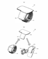
- FIGS. 9A and 9B are a perspective view and a cross-sectional view showing the entire configuration of the clip 4 for mounting the body motion sensor 40 according to the present embodiment
- FIG. 10 shows the body motion sensor 40 in the clip 4. It is a perspective view which shows the operation
- the body motion sensors 40a and 40b according to the present embodiment are fixed to a bicycle shoe with a clip or the like, and the shoe is attached with a cleat for a general bicycle clipless pedal. It is assumed that the shoes are fixed to the pedals via.
- Each body motion sensor 40 can be easily attached to the wearer's clothes, shoes, or the like via the clip 4 by being attached to the clip 4.
- the clip 4 is a device that is detachably attached to the groove portion of the body motion sensor 40, and has a gripping member 42 for attaching to the wearer's clothes and the like in a state where the body motion sensor 40 is attached.
- the gripping member 42 is a tongue-like member that protrudes toward the bottom surface side of the rectangular main body frame 44, and is integrally formed via a connecting portion 44 a that forms part of a recess 41 formed in the main body frame 44. ing.
- the gripping member 42 is held in a state parallel to the bottom surface of the main body frame 44 by the elastic force of the connecting portion 44a.
- the edge of the clothing is formed by the bottom surface of the main body frame 44 and the gripping member 42.
- the other parts can be sandwiched and gripped.
- a stopper 43 for fixing the body motion sensor 40 fitted in the recess 41 is formed at the rear end portion of the main body frame 44.
- the stopper 43 is a fixed portion that fixes the body motion sensor 40 that is fitted in and engaged with the concave portion 41.
- the stopper 43 is connected to the gripping member 42, and the body is pulled by a reaction force that the gripping member 42 grips other parts.
- the motion sensor 40 is pressed and fixed. More specifically, the stopper 43 is formed integrally with the rear end portion of the gripping member 42 and is connected to the main body frame 44 via a connecting portion 44a formed in the concave portion 41 of the main body frame 44.
- the recessed portion 41 is provided with a flange portion 41a that protrudes so that a groove portion provided on each side portion of the body motion sensor 40 is fitted. Then, as illustrated in FIG. 10, when attaching the body motion sensor 40 to the clip, the body motion sensor 40 is slid into the recess 41 in the direction of the arrow in the drawing so that the flange portion 41a is inserted into the groove portion. In this way, it is fitted and fitted.
- the stopper 43 is biased so as to press the rear end portion of the body motion sensor 40 forward, so that the flange portion 41a and the groove portion are Are firmly engaged and fixed.
- the elastic force of the connecting portion 44a is opposed.
- the gripping member 42 is pushed down away from the main body frame 44, and the stopper 43 is raised to more firmly fix the body motion sensor 40.
- the engaging force by the stopper 43 is weakened by removing the clip 4 from the other part 5 held by the holding member 42 and the bottom surface of the main body frame 44.
- the groove portion can be removed from the flange portion 41 a by pushing down the stopper 43, and the body motion sensor 40 can be easily detached from the clip 4.
- the clip 4 is provided with a locking portion for locking a binding member such as a shoelace, for example, for attachment to a part such as a shoelace of a sports shoe.
- FIG. 12 is a perspective view showing an operation when the clip 4 according to this embodiment is attached to another part.
- the gripping member 42 has cuts 42 a, 42 b, 42 b at both end portions, and as shown in FIG.
- a binding member such as a shoelace 51 inserted between the gripping member 42 and the clip member 4
- the clip 4 can be fixed to the upper surface of the sports shoe, that is, the upper part of the wearer's foot.
- the body motion sensor 40 can be easily attached to the wearer's body, and the body can be pressed by pushing down the stopper 43.
- the motion sensor 40 can be easily detached from the clip 4.
- a locking hole 44b to which a string or a strap can be attached is formed at the front end portion of the main body frame 44, and another fastening member may be locked using the locking hole 44b.
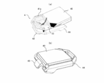
- FIGS. 4 to 6 show the overall configuration and usage of the information terminal device according to this embodiment.
- the information terminal device 100 according to the present embodiment is a wristwatch-type wearable terminal that can be worn by a user with a belt member 104, or a bicycle handle portion or the like as shown in FIG. It is configured so that it can be mounted on.
- the information terminal device 100 is configured to be selectively combined with the belt member 104 or the dock device 101b.
- the information terminal device 100 and the dock device 101b or the belt member 104 are also detachable from each other, and can be separated and combined as appropriate.
- the information terminal device 100 and the dock device 101b have many types with different additional functions and designs depending on the purpose of use, and can be appropriately selected and changed in combination according to the purpose.
- a docking device 101b to which the information terminal device 100 is combined is attached with a mounting device 101 for mounting on a handle portion of a bicycle, or a power supply device 101c. As an extension battery can be installed.
- the information terminal device 100 is worn as a wristband on the user's arm or the like using the belt member 104 as a wearing terminal, or the clamp of the mounting device 101 is connected to the handle 102 portion of the bicycle. It is possible to continue to use one (one type) information terminal device for both motorcycles and runs, and the sensors attached to the body can be used for both motorcycles and runs. And can be used seamlessly.
- the operation unit 100c provided with operation buttons, a touch panel, etc., and the display unit (100a or 100b) can be separated, and the event and measurement of the competition Depending on the purpose, the display can be replaced with a large one (large display 100b) and a small one (small display 100a). Accordingly, it is possible to appropriately select whether to give priority to the information display capability according to the area of the display or to give priority to power saving due to the small size of the apparatus.
- the same belt member 104 can be mounted regardless of which of the large display 100b and the small display 100a is selected and connected to the operation unit 100c.
- the small display 100a and the large display 100b have a liquid crystal display on the upper surface, and an engagement structure and an electrical connection connector for connecting to the operation unit 100c on the side surface.
- An engagement structure for engaging with the belt member 104 is provided on the bottom surface of the small display 100a and large display 100b and the operation unit 100c.
- the belt member 104 is a member for mounting the information terminal device 100 on the arm, and various belts can be used according to the use of the user. Various belts such as a metal belt, a rubber belt, a leather belt, and a nylon belt can be used. Is selectable.
- the small display 100a and the large display 100b are inclined and engaged with the operation unit 100c. After the engagement, the information terminal device 100 bends in the shape of a dogleg as a whole. It follows the roundness of the wearer's arm.
- the small display 100a and the large display 100b are displays for displaying messages and input characters to the user, and a touch panel is integrally formed on the upper surface thereof.
- This touch panel detects a touched position on the display by a detection method such as a pressure sensitive type, an optical type, an electrostatic type, or an electromagnetic induction type, for example, in units of dots constituting the display.
- the signal of “touch position” is output as the touch position.
- the touch position is expressed in the XY coordinate system set as the coordinate system of the detection surface of the touch panel.
- the user can perform various operation inputs by touch operations on the display using an attached touch pen, a finger, or the like.
- This waterproof touch panel detects the touched position on the display and outputs the detection signal as the touch position even on the water surface by a special capacitance detection method.
- the touch position is expressed in the XY coordinate system set as the coordinate system of the detection surface of the touch panel. Even in an environment where the water surface is attached, the user can perform various operation inputs by touch operations on the display.
- the watch body can also be operated with a mechanical button provided on the watch body.
- the small display 100a is sized to fit within the width of the belt member 104 and has a substantially trapezoidal shape.
- the large display 100b has a shape that is expanded laterally from the range of the width of the belt member 104, and the expanded shape portion protrudes in the arm direction opposite to the wrist of the wearer. It has a shape.
- the operation unit 100c is provided with a GPS antenna and a radio antenna in the exterior case.
- the GPS antenna is a satellite orbit information included in the navigation message from a 1.5 GHz band satellite signal extracted by a SAW filter (not shown), GPS An antenna for wireless communication (first antenna) that acquires satellite information such as time information or position information, and is formed of a conductive member such as stainless steel.
- the wireless antenna built in the operation unit 100c is an antenna for BTLE (Bluetooth (registered trademark) Low Energy), which is an ultra-low power short-range wireless standard, and is a small size worn on various sensors and bodies. It is for communicating with other devices. This wireless antenna is also formed of a conductive member such as stainless steel.
- the operation unit 100c is equipped with operation buttons for manual operation by the user on its side surface, and a touch panel, a status display LED, and the like are arranged on the surface of the operation unit 100c. ing. Further, in the present embodiment, the operation unit 100c has a waterproof function and also has a function of processing radio waves (radio signals) from GPS satellites to acquire and display speed information and position information. . Further, the operation unit 100c may be provided with a function as an action meter based on measurement of acceleration due to body movement by incorporating an acceleration sensor or the like.
- the docking device 101b is an information terminal device that is detachably engaged with the information terminal device 100, and is a box having a concave portion that is bent to match the outer shape of the information terminal device 100.
- the docking device 101b is formed of, for example, a synthetic resin such as cured plastic, and includes an information terminal device such as a CPU inside.
- the dock device 101b has a dock-side connection terminal (first connection terminal) 21 formed on the upper surface thereof, and the bottom of the outer case of the information terminal device 100 via the dock-side connection terminal. Is detachably engaged.
- a terminal-side connection terminal is provided at a position corresponding to the dock-side connection terminal at the bottom of the information terminal device 100, and the dock-side connection terminal comes into contact with the terminal-side connection terminal, so that the dock device 101b and the information terminal device 100 are electrically connected.
- the information terminal device 100 and the dock device 101b supply power to the information terminal device 100 from the dock device 101b or display on the small display 100a and the large display 100b via the dock side connection terminal. Data transmission / reception is performed.
- the dock device 101b is detachably mounted with a battery and has an RFID communication function capable of reading and writing data in a non-contact manner via wireless radio waves, and the dock device 101b.
- Wireless communication with an external reader / writer device is possible using a wireless antenna for wireless communication provided in the device.
- This wireless antenna is a non-contact wireless communication (NFC (Near Field Communication)) antenna that transmits and receives data using weak radio waves transmitted from an external reader / writer device.
- the docking device 101b includes a USB terminal that is electrically connected to an external device such as a personal computer.
- the USB terminal is an external terminal that is provided outside the dock device 101b and is connected to the external device via a USB cable, and is installed in a connector that protects the USB terminal disposed on the side of the dock device 101b. Has been.
- the power supply device 101c is a device that is detachably engaged with the bottom of the dock device 101b and supplies power to or charges the information terminal device 100 and the dock device 101b.
- the power supply device 101c may be an indoor installation type such as a user's house or a portable type installed in an automobile, a bicycle, or the like.
- an indoor installation type power is supplied via an outlet and a power cable
- a battery for storing power supplied from an external AC adapter device is provided. You may do it.
- the battery may incorporate a transformer, a rectifier, a stabilization circuit, or the like that converts alternating current into direct current.
- the configuration of the power supply device 101c can be changed according to the intended use. For example, when installed on a table or the like, an installation table is provided on the lower surface, and when installed on a bicycle. In addition, an attachment part for storing or fixing to the handle portion may be attached.
- the information terminal device 100 includes a wireless interface 113, a control unit 170, a memory 114, an output interface 111, and an input interface 112.
- the information terminal device 100 has a function of collecting detection results detected by each body motion sensor 40, and performs communication processing with each body motion sensor 40 by the wireless interface 113.
- the detection result can be acquired.
- the memory 114 of the information terminal device 100 functions as a body motion recording unit that records the detection result of the body motion sensor 40 as body motion data.
- the body movement data is raw data detected by various sensors, and data obtained by recording and analyzing the body movement data, extracting necessary information, and correcting the body movement data is the body movement reproduction data.
- sensor identification information for identifying each body motion sensor 40 is added to the detection result transmitted from each body motion sensor 40, and the identification information is accumulated in the memory 114 of the information terminal device 100.
- the control unit 170 can determine from which body motion sensor 40 the detection result is acquired when acquired from the wireless interface 113.
- the identification information includes mounting part information for specifying the mounting part of each sensor, and body motion reproduction data can be calculated based on the mounting part information.
- the body motion data includes time information when a detection result is acquired from each body motion sensor 40.
- the information terminal device 100 includes a wireless interface 113 as a communication function.
- the wireless interface 113 is a module that controls transmission / reception of various information via a communication network and short-range wireless communication such as wifi and Bluetooth (registered trademark), and communicates with each body motion sensor 40 by various protocols.
- data is transmitted to and received from the server device or the like by 3G communication.
- the information terminal device 100 has an output interface 111 that displays or outputs an analysis result for the body movement reproduction data, and the display information generated by the display information generation unit 170e is displayed on the display 100a or 100b through the output interface 111. Is displayed.
- the information terminal device 100 has a function of analyzing the body movement of the wearer based on the body movement data acquired from each sensor and generating body movement reproduction data.
- the information terminal device 100 includes a control unit 170, and this control unit 170 is an arithmetic processing device such as a CPU that performs various calculations necessary for controlling each unit. is there.
- Each function of the large display 100b is virtually constructed on the control unit 170 by executing the motion capture program of the present invention in the control unit 170.
- control unit 170 executes the body motion data acquisition unit 170a, the body motion calculation unit 170b, the period extraction unit 170c, the analysis unit 170d, and the display information generation unit 170e by executing the motion capture application.
- the control unit 170 executes the body motion data acquisition unit 170a, the body motion calculation unit 170b, the period extraction unit 170c, the analysis unit 170d, and the display information generation unit 170e by executing the motion capture application.
- the body motion data acquisition unit 170a is a module that acquires body motion data from each body motion sensor 40 via the wireless interface 113.
- the body motion data acquisition unit 170a performs wireless communication with each body motion sensor 40a to 41e, The body motion data as these detection results is acquired.
- the body motion data is temporarily stored in the memory 114, and then each detection result by the body motion sensor 40 is transmitted to the body motion calculation unit 170b.
- the body motion calculation unit 170b is based on the detection results by the body motion sensors 40a and 40b accumulated in the memory 114 (body motion recording unit), the displacement and rotation of each body motion sensor 40, and their accelerations. This is a module for calculating body motion as body motion reproduction data.
- each detection result by the body motion sensor 40 is a value measured by a so-called nine-axis sensor.
- the direction and magnitude of acceleration including gravitational acceleration
- the object Angular velocity magnitude, direction, center position
- magnitude / direction direction of the magnetic field.
- the calculated body motion includes an indicator of pedaling smoothness, an angular velocity ⁇ of the pedal axis of the bicycle, a temporal change in the angular velocity ⁇ , and a smoothness of the change.
- the body motion sensor 40 is attached to the left and right shoes, and the rotational motion detected by the sensors is the rotation of the shoes, but when riding a bicycle, the shoes rotate around the pedal axis. Let the angular velocity of this pedal shaft be ⁇ .
- the body motion calculation unit 170b includes a period extraction unit 170c.
- the period extracting unit 170c extracts a periodic change included in the body movement based on the body movement reproduction data stored in the memory 114.
- This periodic change includes not only a simple circular motion but also complex free circular trajectories C1 and C2 which are three-dimensional and combined with a figure 8 and a wave motion as shown in FIG.
- the orbital motion by the right foot motion sensor 40a attached to the back of the right foot of the wearer 1 is extracted as C1a
- the orbital motion by the left foot motion sensor 40b attached to the back of the wearer's left foot is extracted as C1a.
- C1a and C1b perform circular motions whose main component is a direction along the plane xy including the traveling direction x and the vertical direction y of the wearer 1 during running and cycling.
- the analysis unit 170d also has a function of analyzing the pattern of the circular motion, and by automatically extracting the characteristics of the circular motion, the event of the current competition is automatically determined and suitable for the event.
- the processing setting can be switched.
- the rotation axis is estimated from the three-axis gyro value by the following equation.
- the normalized axis is used as the rotation axis (RotationAxis) as shown in the following equation.
- the body motion calculation unit 170b uses the body motion of the wearer as body motion reproduction data based on the detection results of the body motion sensor 40 and the change characteristics of the circular motion of the body motion sensor 40. calculate. At this time, the body motion calculation unit 170b calculates, for example, a three-dimensional free-circulation locus C1 of each body motion sensor 40 as shown in FIG. Then, the body motion calculation unit 170b evaluates the disruption of the orbital movement in each of the left and right of the wearer based on the characteristic change of the calculated free orbital locus C1 (C1a and C1b). Then, the body motion reproduction data is calculated based on the free circulation locus C1 thus calculated.
- the analysis unit 170d is a module that analyzes the body movement of the wearer 1 based on the body movement reproduction data.
- the analysis unit 170d functions as a characteristic analysis unit that analyzes the characteristics of the angular velocity change in the periodic motion extracted by the period extraction unit 170c.
- the characteristics analyzed here are extracted by the period extraction unit 170c. It is displayed or output by an output device corresponding to the rotation angle of the periodic motion.
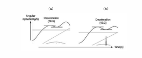
- the angular velocity ⁇ of the pedal generally shows a shape close to a sine wave as shown in FIG. 13A, and the tendency is remarkable in skilled players, As shown in FIGS. 2B and 2C, this shape tends to collapse in an amateur or in a fatigued state, so that there is no smooth sine wave.
- the difference between the maximum value and the minimum value at the local peak when the sine wave collapses indicates the degree of the characteristic of the angular velocity change in the periodic motion. Evaluate as a score. In the example shown in FIG. 14, (a) has a score of 16.5, (b) has a score of 40.2, and (b) is evaluated as having a greater collapse.
- the pedal position is estimated.
- the cause of the deceleration of the pedal angular velocity ⁇ (MainComponentGyro) occurs somewhere when the pedal crank is rotated.
- the position of the same sensor is used to indicate the position to the wearer 1 as an analysis result of the angular velocity change characteristic.
- the pedal position is estimated using the acceleration.
- Bicycle cranks typically rotate in the range of 30 to 200 rpm.
- the crank length is generally about 160 mm to 180 mm, and depending on the position where the body motion sensor 40 is mounted, it rotates at about 100 rpm in a state about 200 to 300 mm away from the center of rotation.
- the centrifugal force applied to the sensor is expressed by the following equation as an ideal value.
- a centrifugal force of 3 times or more of the gravitational acceleration is applied, and a centrifugal force of 1 time is applied even at a rotation speed of 30 rpm.
- the vector length indicated by the 3-axis accelerometer shows the minimum value when the pedal and the centrifugal force cancel each other near the top dead center, and the centrifugal force and the gravitational acceleration add near the bottom dead center. The maximum value is shown.
- the length of the vector is simply calculated by the following equation, and the pedal position can be estimated by linearly interpolating the other with the maximum value as the bottom dead center and the minimum value as the top dead center.
- this analysis part 170d based on body movement reproduction data, you may generate
- the analysis based on each user information may be performed by registering user information such as sex, height, weight, and age in advance. Then, the analysis unit 170d transmits the analysis results such as the stereoscopic image data and the improvement data to the information terminal device 100.
- the display information generation unit 170e is a module that generates display information displayed on the output interface 111, and displays or analyzes the characteristics analyzed by the analysis unit 170d in correspondence with the rotation angle of the periodic motion extracted by the period extraction unit 170c. Generate display information for output.
- the display information represents the periodic motion extracted by the period extraction unit 170c as a planar circle as shown in FIG. 8, and the rotation angle at which each characteristic of the periodic motion analyzed by the analysis unit 170d appears.
- the intensity of the periodic motion characteristic is expressed by the distance from the circular origin, and the change of the periodic motion characteristic is expressed by a symbol, a figure, or their color or size. Note that this display information includes display signals and acoustic signals and other output control signals.
- the memory 114 is a storage device that records various data, and includes identification information for identifying each information terminal device 100, wearing part information of each body motion sensor 40, and a relative position of the body motion sensor 40 attached to each part. The relationship, the above-described user information, model body motion data, and the like are accumulated.
- FIG. 7 is a sequence diagram showing a motion capture method according to this embodiment.
- coaching is performed in a bicycle competition will be described as an example.
- the wearer 1 wears the body motion sensors 40a and 40b on both feet. Further, the wearer 1 fixes the information terminal device 100 to the bicycle handle 102 via the mounting device 101 and the dock device 101b, and charges the information terminal device 100 from the dock device 101b and the power source device 101c. Perform motion capture.
- the competition event may be selected by a user operation, or the characteristics of the above-mentioned circular motion are extracted, and the competition event preset in advance is automatically discriminated from the extracted pattern, and suitable for the event.
- the processing settings can be switched. With this function, even if the sporting event is switched halfway, measurement can be continued seamlessly without requiring special scanning.
- each body motion sensor 40 detects the operation of the wearer 1. Specifically, the three-dimensional displacement or acceleration of each part is detected by the body motion sensor 40 attached to each part of the wearer's body (S102).
- each acquired detection result is transmitted to the wireless interface 113 of the information terminal device 100 by weak radio waves via the wireless communication unit of each body motion sensor 40 (S103).
- the memory 114 serving as a body motion recording unit records the detection result by the body motion sensors 40a and 41b as body motion data (S203).
- the period extraction unit 170c transmits each detection result by the body motion sensor 40 to the body motion calculation unit 170b.
- the body motion calculation unit 170b calculates the body motion of the wearer as body motion reproduction data based on each detection result by the body motion sensor 40 accumulated in the body motion recording unit and the relative positional relationship of each body motion sensor 40.
- the body motion reproduction data is transmitted to the analysis unit 170d (S204).
- the analysis unit 170d corrects the body motion reproduction data calculated by the body motion calculation unit 170b when a predetermined cycle arrives based on the detection result by the cycle extraction unit 170c (S206).
- the analysis unit 170d analyzes the wearer's body movement based on the body movement reproduction data (S207).
- the data of the analyzed analysis result is displayed or output by the sound by the display 100a or 100b or the speaker (S208).
- the pattern is collated to automatically determine the current sporting event, and the competition It is possible to switch to a measurement setting suitable for the event (S210).
- Motion capture program The above-described motion capture system and motion capture method according to the present invention are realized by executing the motion capture program of the present invention described in a predetermined language on a computer like the above-described motion capture application. Can do. That is, the program of the present invention is installed in a mobile terminal device, a smart phone, a wearable terminal, a mobile PC or other information processing terminal, an IC chip or a memory device of a general-purpose computer such as a personal computer or a server computer, and executed on the CPU.
- a motion capture method can be implemented by constructing a system having each function described above.
- the body motion is detected with respect to a periodic motion such as riding a bicycle, and the characteristics of the periodic motion are displayed or output in correspondence with the rotation angle. You can instantly understand the occurrence of form disturbance and rhythm disruption when you step on.
- the body motion sensor can be disposed on footwear worn below the ankle, such as sports shoes, and the body motion sensor can be worn together with the footwear, Mounting becomes easy.
- the body motion sensor can be mounted freely in the mounting position and mounting direction, usability can be improved.
- the output device represents the periodic motion extracted by the period extraction unit as a planar circle, and the characteristics analyzed by the characteristic analysis unit indicate the rotation angle at which each characteristic appears as the center of the circle. Since it is displayed by an angle, the periodic motion can be geometrically expressed according to the rotation angle, and the characteristics of the periodic motion can be understood at a glance.
- a package application that can be distributed via a communication line and that operates on a stand-alone computer by recording on a computer-readable recording medium.
- the recording medium can be recorded on various recording media such as a magnetic recording medium such as a flexible disk and a cassette tape, an optical disk such as a CD-ROM and a DVD-ROM, and a RAM card.
- the computer-readable recording medium on which the program is recorded the above-described system and method can be easily implemented using a general-purpose computer or a dedicated computer, and the program can be stored, transported, and Easy installation.
Abstract
装着者(1)の周期的な運動が行われる部位に装着され、各部位の三次元的な変位又は加速度を測定可能な複数の体動センサー(40)と、検出結果を体動データとして記録するメモリ(114)と、蓄積された体動データに基づいて、各体動センサー(40)の周期運動を抽出する周期抽出部(170c)と、抽出した周期運動における角速度変化の特性を解析する解析部(170d)と、解析部(170d)が解析した特性を、周期抽出部(170c)が抽出した周期運動の回転角度に対応させて表示又は出力するディスプレイ(100a,100b)とを備え、複雑な体動を瞬時に理解できるように表示・出力する。
Description
本発明は、いわゆるスマートフォンやウェアラブルタイプ、その他の情報端末装置を用いたモーションキャプチャシステム、モーションキャプチャプログラム及びモーションキャプチャ方法に関する。
近年、情報端末装置の小型・軽量化、多機能化が進み、ユーザーの身体に装着可能ないわゆるウェアラブル端末と呼ばれる装着型情報処理端末が普及しつつあり、このウェアラブル端末は、軽量であるうえ、時計機能やGPS機能の他、心拍センサー等の各種センサー類との通信機能などを備えていることから、ランニングやウォーキング、自転車等のスポーツトレーニングやエクササイズ時に装着して、その体動を記録したりモニタリングしたりするシステムが開発されている(例えば、特許文献1)。
この特許文献1に開示されたシステムによれば、ユーザーの靴底に運動パラメータを測定する装置を取り付け、運動活動中の運動者のモニタリングにより得られる運動パラメータを、基本的なベースラインデータと比較して、その比較結果が許容範囲内にあるか否かに応じて、再生される音楽を変化させるなどして、運動活動時におけるリアルタイムのフィードバックをユーザーに与えることができる。
しかしながら、人間の体動はその可動部分や動きが複雑であり、それを数値化するパラメーターも多数あることから、その多数ある運動パラメーターの変化を運動活動中にユーザーに対して表示するためのユーザーインターフェイスが望まれている。特に、運動中にリアルタイムに体動をキャプチャし、そのキャプチャー結果に基づくコーチングを行うような場合には、リアルタイムに変換するパラメーターを、ユーザーが瞬時に理解できるように表示させる必要がある。
そこで、本発明は、上記のような問題を解決するものであり、ユーザーの身体の運動活動をキャプチャーするシステムにおいて、複雑な体動を瞬時に理解できるように表示・出力するモーションキャプチャシステム、モーションキャプチャプログラム及びモーションキャプチャ方法を提供することを目的とする。
上記課題を解決するために、本発明は、 装着者の体動を検出するモーションキャプチャシステムであって、
前記装着者の周期的な運動が行われる部位に装着され、各部位の三次元的な変位又は加速度を測定可能な複数の体動センサーと、
前記体動センサーによる検出結果を体動データとして記録する体動記録部と、
前記体動記録部に蓄積された前記体動データに基づいて、前記各体動センサーの周期運動を抽出する周期抽出部と、
前記周期抽出部が抽出した前記周期運動における角速度変化の特性を検出する特性解析部と、
前記特性解析部が解析した特性を、前記周期抽出部が抽出した前記周期運動の回転角度に対応させて表示又は出力する出力デバイスと
を備えることを特徴とする。
前記装着者の周期的な運動が行われる部位に装着され、各部位の三次元的な変位又は加速度を測定可能な複数の体動センサーと、
前記体動センサーによる検出結果を体動データとして記録する体動記録部と、
前記体動記録部に蓄積された前記体動データに基づいて、前記各体動センサーの周期運動を抽出する周期抽出部と、
前記周期抽出部が抽出した前記周期運動における角速度変化の特性を検出する特性解析部と、
前記特性解析部が解析した特性を、前記周期抽出部が抽出した前記周期運動の回転角度に対応させて表示又は出力する出力デバイスと
を備えることを特徴とする。
また、本発明は、装着者の体動を検出するモーションキャプチャ方法であって、
前記装着者の周期的な運動が行われる部位に装着された体動センサーにより、各部位の三次元的な変位又は加速度を測定するとともに、前記体動センサーによる検出結果を体動データとして体動記録部に記録する体動記録ステップと、
前記体動記録部に蓄積された前記体動データに基づいて、周期抽出部が、前記各体動センサーの周期運動を抽出する周期抽出ステップと、
前記周期抽出ステップで抽出した前記周期運動における角速度変化の特性を特性解析部が解析する特性解析ステップと、
前記特性解析ステップで解析した特性を、前記周期抽出ステップで抽出した前記周期運動の回転角度に対応させて出力デバイスが表示又は出力する出力ステップと
を含むことを特徴とする。
これらの発明によれば、例えば自転車を漕ぐような周期的な運動について体動を検出し、その周期的な運動の特性を回転角度に対応させて表示又は出力することによって、自転車のペダルを踏み込むときのフォームの乱れやリズムの崩れ等の発生を瞬時に理解できる。
上記発明において前記体動センサーは、前記装着者の両足首よりも下の部位に装着されることが好ましい。この場合には、例えばスポーツシューズなど、足首よりも下に装着する履物に体動センサーを配置することができ、履物とともに体動センサーを装着できることから、体動センサーの装着が容易となる。
上記発明において前記出力デバイスは、前記周期抽出部が抽出した前記周期運動を平面的な円形で表し、前記特性解析部が解析した特性を、各特性が出現する回転角度を前記円形の中心角度によって表示することが好ましい。この場合において前記出力デバイスは、前記体動センサーが解析した特性の強度を前記円の原点からの距離により表示することができる。また、このとき、前記出力デバイスは、前記体動センサーが解析した特性の変化を記号、図形又はこれらの色彩若しくはサイズによって表現するようにしてもよい。この場合には、自転車のペダルを漕ぐような周期的な運動を、その回転角度に応じて幾何学的に表現することができ、周期運動の特性を一目で理解することができる。
以上述べたように、この発明によれば、ユーザーの身体の運動活動をキャプチャーするシステムにおいて、複雑な体動を瞬時に理解できるように表示・出力することができ、運動フォームにおけるパラメータ相互の影響を分析して、適切に運動フォームの崩れを調整できる。特に、本発明によれば、装着位置や装着方向を自由に体動センサーを装着できるため、ユーザビリティの向上を図ることができる。
なお、上述した本発明に係るモーションキャプチャシステム及びモーションキャプチャ方法は、所定の言語で記述された本発明のモーションキャプチャプログラムをコンピューター上で実行することにより実現することができる。すなわち、本発明のプログラムを、携帯端末装置やスマートフォン、ウェアラブル端末、モバイルPCその他の情報処理端末、パーソナルコンピュータやサーバーコンピューター等の汎用コンピューターのICチップ、メモリ装置にインストールし、CPU上で実行することにより、上述した各機能を有するシステムを構築してモーションキャプチャ方法を実施することができる。
このような本発明のモーションキャプチャプログラムでは、例えば、通信回線を通じて配布することが可能であり、また、コンピューターで読み取り可能な記録媒体に記録することにより、スタンドアローンの計算機上で動作するパッケージアプリケーションとして譲渡することができる。この記録媒体として、具体的には、フレキシブルディスクやカセットテープ等の磁気記録媒体、若しくはCD-ROMやDVD-ROM等の光ディスクの他、RAMカードなど、種々の記録媒体に記録することができる。そして、このプログラムを記録したコンピューター読み取り可能な記録媒体によれば、汎用のコンピューターや専用コンピューターを用いて、上述したシステム及び方法を簡便に実施することが可能となるとともに、プログラムの保存、運搬及びインストールを容易に行うことができる。
以下、本発明の実施形態について図面を参照して説明する。本実施形態では、一つの情報端末装置100を用いて、トライアスロン競技のバイクとランといったような複数種の競技についての計測及びコーチングを可能とするシステムを提供する。なお、以下に示す実施の形態は、この発明の技術的思想を具体化するための装置などを例示するものであって、この発明の技術的思想は、各構成部品の材質、形状、構造、配置などを下記のものに特定するものでない。この発明の技術的思想は、特許請求の範囲において、種々の変更を加えることができる。
(システムの構成)
図1は、本実施形態に係る情報端末装置100を用いたモーションキャプチャシステムの使用態様を示す説明図であり、図2は、本実施形態に係るモーションキャプチャシステムにより取得された体動再現データの一例である。また、図3は、各装置の内部構成を示すブロック図である。
図1は、本実施形態に係る情報端末装置100を用いたモーションキャプチャシステムの使用態様を示す説明図であり、図2は、本実施形態に係るモーションキャプチャシステムにより取得された体動再現データの一例である。また、図3は、各装置の内部構成を示すブロック図である。
図1~図3に示すように、本実施形態に係るモーションキャプチャシステムは、装着者1に装着される情報端末装置100と、装着者の身体各部位に装着され情報端末装置100に対して無線接続される体動センサー40(40a,40b)とから構成されている。なお、本実施形態では、基本的に情報端末装置100と体動センサー40との間における近距離無線通信で構築される範囲でシステムが構築可能となっており、通信ネットワーク上のサーバー等とは実際の測定時には接続されず、いわゆるオフラインでのスタンドアローンとして、システムの運用が可能となっている。
(各装置の構成)
(1)体動センサー
体動センサー40a,40bは、装着者1の周期的な運動が行われる部位に装着され各部位の三次元的な変位又は加速度を検出する一対のセンサーである。本実施形態において体動センサー40a,40bは、装着者1の両足首よりも下の部位に装着されるようになっており、装着者の右足の甲に取り付けられる右足体動センサー40aと、装着者の左足の甲に取り付けられる左足体動センサー40bとから構成されている。これら体動センサー40a及び41bは、物体の加速度を計測する3軸加速度計と、物体の角速度を検出する3軸ジャイロスコープ、磁場の大きさ・方向を計測する3軸磁気センサーが搭載され、9軸の動きを検知可能となっている。
各体動センサー40は、クリップ等の部材などによって装着者の靴などに着脱可能であり、靴を履いたり脱いだりする日常的な感覚で装着者が各センサーを着脱して測定を行うことができ、装着者に負担を与えずに継続的な測定を行うことが容易である。
そして、これらの体動センサー40(各体動センサー40a,40b)は、図3に示すように、それぞれ無線通信部を有している。この無線通信部は、内部にアンテナを有し、BTLE(Bluetooth(登録商標) Low Energy,Bluetooth(登録商標) 4.0)等による近距離無線通信のデータ通信用プロトコルを実行する機能によって、情報端末装置100と通信処理が可能となっている。なお、本実施形態において、各体動センサー40の無線通信部は、低消費電力通信用のプロトコルとしてBTLEを採用したが、例えば、ANT、ANT+等を採用することもできる。また、通常のBluetooth(登録商標)を採用することもできる。
次いで、上記体動センサー40a,40bを装着者1が身体に装着するために用いられるクリップ4について説明する。図9(a)及び(b)は、本実施形態に係る体動センサー40を取り付けるためのクリップ4の全体構成を示す斜視図及び断面図であり、図10は、体動センサー40をクリップ4に取り付ける動作を示す斜視図である。なお、本実施形態に係る体動センサー40a,40bは、自転車用のシューズにクリップなどで固定され、そのシューズは一般的な自転車用のクリップレスペダル用のクリートが装着してあり、運動時にはクリートを介してシューズはペダルに固定されることを前提としている。
上記各体動センサー40は、クリップ4に取り付けることによって、クリップ4を介して装着者の衣服や靴などに簡単に取り付けることができる。具体的にクリップ4は、体動センサー40の溝部に着脱自在に取り付けられる器具であり、体動センサー40が取り付けられた状態において、装着者の衣服などに取り付けるための把持部材42を有する。この把持部材42は、矩形状をなす本体フレーム44の底面側に突出された舌状の部材であり、本体フレーム44に形成された凹部41の一部をなす連結部44aを介して一体形成されている。そして、この把持部材42は、連結部44aの弾性力により本体フレーム44の底面と平行な状態が保持され、図11に示すように、本体フレーム44底面と把持部材42とにより、衣類の縁部のような、他の部位を挟み込んで把持できるようになっている。
また、この本体フレーム44の後端部分には、凹部41内に嵌め込まれた体動センサー40を固定するストッパー43が形成されている。このストッパー43は、凹部41に嵌め込まれて係合された体動センサー40を固定する固定部であり、把持部材42と連設され、把持部材42が他の部位を把持する反力により、体動センサー40を押圧して固定するようになっている。詳述すると、ストッパー43は、把持部材42の後端部分に一体的に形成され、本体フレーム44の凹部41に形成された連結部44aを介して、本体フレーム44に接続されており、連結部44aの弾性力に逆らって把持部材42が本体フレーム44から離れるように押し下げられると、ストッパー43が上昇し、ストッパー43を押し下げると、把持部材42が把持するようになっている。そして、凹部41には、体動センサー40それぞれの側部に設けられた溝部が嵌合されるように突出されたフランジ部41aが設けられている。そして、図10に例示するように、体動センサー40をクリップに取り付ける際には、溝部にフランジ部41aが差し込まれるように、図中矢印の方向に体動センサー40を凹部41内へ滑り込ませるようにして嵌め込み、嵌合させる。
この体動センサー40が凹部41に対して嵌合された状態では、ストッパー43が、体動センサー40の後端部を前方に向けて押圧するように付勢されるため、フランジ部41aと溝部とが強固に係合されて固定される。この体動センサー40を凹部41に嵌合した状態で、把持部材42と、本体フレーム44底面とにより、衣類の縁部のような他の部位5を挟み込むと、連結部44aの弾性力に逆らって把持部材42が本体フレーム44から離れるように押し下げられることとなり、ストッパー43が上昇してより強固に体動センサー40が固定されることとなる。なお、体動センサー40をクリップ4から取り外す際には把持部材42と本体フレーム44底面とによって把持していた他の部位5からクリップ4を取り外すことにより、ストッパー43による係合力が弱まり、ストッパー43が押し下げやすくなり、ストッパー43を押し下げてやることにより、フランジ部41aから溝部を外すことができ、体動センサー40がクリップ4から容易に取り外せるようになる。
さらに、クリップ4には、例えば、スポーツシューズの靴紐などの部位に取り付けるため、靴紐等の緊結部材を係止するための係止部が設けられている。図12は、本実施形態に係るクリップ4を他の部位に取り付ける際の動作を示す斜視図である。
具体的には、図9にも示したように、把持部材42には、両側端部に切込42a,42b,42bが形成されており、図12に示すように、本体フレーム44の下面と、把持部材42との間に挿通された靴紐51等の緊結部材を引っ掛けることにより、このクリップ4をスポーツシューズの上面、すなわち装着者の足の甲上部にクリップ4を固定することができる。これによりこのスポーツシューズ上面に固定されたクリップ4に、体動センサー40を取り付けることにより、容易に体動センサー40を装着者の身体に装着させることができ、また、ストッパー43を押し下げることで体動センサー40をクリップ4から簡単に取り外すことができる。なお、本体フレーム44の前端部には紐やストラップが取り付け可能な係止孔44bが形成されており、この係止孔44bを利用して他の緊結部材を係止するようにしてもよい。
(2)情報端末装置
図4~図6は、本実施形態に係る情報端末装置の全体構成及び使用態様を示す。本実施形態に係る情報端末装置100は、図4及び図5に示すように、ベルト部材104によってユーザーが装着可能な腕時計タイプのウェアラブル端末としたり、図6に示すように、自転車のハンドル部分等にマウントしたりできるように構成されている。
図4~図6は、本実施形態に係る情報端末装置の全体構成及び使用態様を示す。本実施形態に係る情報端末装置100は、図4及び図5に示すように、ベルト部材104によってユーザーが装着可能な腕時計タイプのウェアラブル端末としたり、図6に示すように、自転車のハンドル部分等にマウントしたりできるように構成されている。
詳述すると情報端末装置100は、図4(b)に示すように、ベルト部材104又はドック用装置101bに選択的に合体できるように構成されている。情報端末装置100と、ドック用装置101b又はベルト部材104も相互に着脱可能となっており、必要に応じて適宜分離・合体できるようになっている。また、情報端末装置100やドック用装置101bは、使用目的によりそれぞれの追加機能やデザインが異なる多数の種類があり、目的に応じて、適宜選択して組み合せを自由に変えることができる。例えば、図4(b)や図6に示すように、情報端末装置100が合体されるドック用装置101bには、自転車のハンドル部分にマウントするためのマウント器具101を取付けたり、電源用装置101cとして拡張用のバッテリーを装着したりできるようになっている。
また、情報端末装置100は、本実施形態では、装着用端末としてベルト部材104を用いてユーザーの腕などにリストバンドとして装着したり、自転車のハンドル102部分などにマウント器具101のクランプを連結して取付けたりできる機能を備えており、一つの(1種類の)情報端末装置をバイクとランの両方の競技にわたって引き続き用いることができるとともに、身体に装着したセンサー類もバイクとランの両方で継続して装着したままシームレスに使用できる。
情報端末装置100自体も、図5(b)に示すように、操作ボタンやタッチパネル等を備えた操作部100cとディスプレイ部(100a或いは100b)とが分離可能となっており、競技の種目や測定目的に応じて、ディスプレイを大型のもの(大型ディスプレイ100b)と小型のもの(小型ディスプレイ100a)と交換できるようになっている。これによりディスプレイの面積応じた情報表示能力を優先させるか、装置の小型による省電力性を優先させるかなどを適宜選択できる。なお、大型ディスプレイ100b若しくは小型ディスプレイ100aのいずれを選択して操作部100cに連結させても、同じベルト部材104に装着できるようになっている。
小型ディスプレイ100a及び大型ディスプレイ100bは、上面に液晶ディスプレイを有し、側面に操作部100cと連結するための係合構造及び電気接続コネクタを備えている。これら小型ディスプレイ100a及び大型ディスプレイ100bと、操作部100cの底面部には、ベルト部材104と係合するための係合構造を備えている。ベルト部材104は、情報端末装置100を腕に装着するための部材であり、ユーザーの用途に応じて種々のベルトを用いることができ、金属ベルト、ラバーベルト、皮ベルト、ナイロンベルトなど種々のベルトが選択可能となっている。
小型ディスプレイ100a及び大型ディスプレイ100bは操作部100cに対して傾斜して係合されるようになっており、係合後は情報端末装置100はその側面形状が全体としてくの字状に屈曲することとなり、装着者の腕の丸みに沿うようになっている。小型ディスプレイ100a及び大型ディスプレイ100bは、ユーザーにメッセージや入力文字などを表示させるディスプレイであり、その上面にタッチパネルが一体的に形成されている。このタッチパネルは、感圧式や光学式、静電式、電磁誘導式等の検出方式によってディスプレイ上のタッチされた位置を、例えばディスプレイを構成するドット単位で検出し、検出した位置(以下、適宜「タッチ位置」という。)の信号をタッチ位置として出力する。タッチ位置は、タッチパネルの検出面の座標系として設定されているXY座標系で表現される。ユーザーは、付属のタッチペンや、指等を用いてディスプレイ上でのタッチ操作により各種の操作入力を行うことができる。
防水対応しているこのタッチパネルは、水面においても、特殊な静電容量検知方式により、ディスプレイ上のタッチされた位置を検出し、検出信号をタッチ位置として出力する。タッチ位置は、タッチパネルの検出面の座標系として設定されているXY座標系で表現される。ユーザーは、水面の付くような環境化でも、ディスプレイ上でのタッチ操作により各種の操作入力を行うことができる。なお、時計本体にも装備されている機械式のボタンでも、時計本体の操作は可能である。
なお、小型ディスプレイ100aは、ベルト部材104の幅の範囲に収まるような大きさであり、略台形形状をなしている。一方、大型ディスプレイ100bは、ベルト部材104の幅の範囲から側方へ向けて拡張された形状をなしており、この拡張された形状部分は、装着者の手首と反対側の腕方向に突出した形状となっている。
操作部100cには、GPSアンテナ,無線アンテナが外装ケース内に配置されており、GPSアンテナは、図示しないSAWフィルタが抽出した1.5GHz帯の衛星信号から航法メッセージに含まれる衛星軌道情報、GPS時刻情報、或いは位置情報等の衛星情報を取得する無線通信用のアンテナ(第1のアンテナ)であり、ステンレスなどの導電性部材で形成されている。また、操作部100cに内蔵された無線アンテナは、極低電力の近距離無線規格であるBTLE(Bluetooth(登録商標) Low Energy)用のアンテナであり、各種のセンサーや体に身につける小型の他の装置との通信を行うためのものである。この無線アンテナも、ステンレスなどの導電性部材で形成されている。
また、本実施形態において、操作部100cには、その側面において使用者が手動操作するための操作ボタンが装備されているとともに、操作部100cの表面はタッチパネルや状態表示用のLEDなどが配置されている。さらに、本実施形態において操作部100cは、防水機能を有しているとともに、GPS衛星からの電波(無線信号)を処理して速度情報や位置情報を取得して表示する機能も有している。また、操作部100cには、加速度センサーなどを内蔵させて、体動による加速度の測定に基づいた行動計としての機能を設けることもできる。
一方、ドック用装置101bは、情報端末装置100と着脱可能に係合される情報端末装置であり、情報端末装置100の外形と合致するように屈曲された凹部を有する函体である。本実施形態において、ドック用装置101bは、例えば、硬化プラスチック等の合成樹脂で形成され、内部にCPUなどの情報端末装置を備えている。そして、本実施形態において、このドック用装置101bは、その上面にドック側接続端子(第1の接続端子)21が形成されており、ドック側接続端子を介して情報端末装置100の外装ケース底部である着脱可能に係合されている。
具体的に、情報端末装置100の底部には、ドック側接続端子に対応する位置に端末側接続端子が設けられており、ドック側接続端子が端末側接続端子と接触することで、ドック用装置101bと情報端末装置100とが電気的に接続されるようになっている。そして、情報端末装置100及びドック用装置101bは、このドック側接続端子を介して、ドック用装置101bから情報端末装置100に対して、電源を供給したり、小型ディスプレイ100a及び大型ディスプレイ100bに表示するためのデータの送受信を行うようになっている。
また、このドック用装置101bには、バッテリーが着脱可能に搭載されているとともに、無線電波を介して非接触でデータの読出しや書き込みが可能なRFID通信機能を有しており、ドック用装置101bに設けられた無線通信用の無線アンテナを用いて、外部のリーダライタ装置と無線通信が可能となっている。この無線アンテナは、外部のリーダライタ装置が発信する弱い電波を利用してデータを送受信する非接触式の無線通信用(NFC(Near Field Communication))のアンテナである。さらに、本実施形態において、ドック用装置101bには、パーソナルコンピュータ等の外部装置と電気的に接続されるUSB端子を備えている。USB端子は、ドック用装置101bの外部に設けられ、USBケーブルを介して外部装置と接続される外部端子であって、ドック用装置101b側部に配置されたUSB端子を保護するコネクタ内に設置されている。
電源用装置101cは、ドック用装置101b底部に着脱可能に係合され、情報端末装置100及びドック用装置101bに対して電源を供給したり、充電したりする装置である。本実施形態において、電源用装置101cは、ユーザー宅などの室内設置型であってもよく、自動車、自転車などに設置される携帯型であってもよい。ここで、室内設置型である場合には、コンセントと電源ケーブルを介して電力が供給され、一方、携帯型である場合には、外部のACアダプタ機器から供給された電源を蓄積するバッテリーを備えるようにしてもよい。なお、このバッテリーには、交流を直流に変換する変圧器や整流器、安定化回路などを内蔵させてもよい。なお、電源用装置101cの構成は、使用される用途に応じて変更可能であり、例えば、テーブル等に設置される場合には、下面に設置台が設けられ、自転車に設置される場合には、ハンドル部分に収納又は固定するためのアタッチメント部品を取り付けるようにしてもよい。
次いで、このような本実施形態に係る情報端末装置100の内部構成について説明する。具体的に情報端末装置100は、図3に示すように、無線インターフェース113と、制御部170と、メモリ114と、出力インターフェース111と、入力インターフェース112とを備えている。
詳述すると、本実施形態に係る情報端末装置100は、各体動センサー40によって検出された検出結果を収集する機能を有し、無線インターフェース113によって各体動センサー40と相互に通信処理を行って、検出結果を取得できるようになっている。情報端末装置100のメモリ114は、体動センサー40による検出結果を体動データとして記録する体動記録部としての機能を果たしている。ここで、体動データとは、各種センサーが検出した生データであり、この体動データを記録し解析し、必要な情報を抽出したり、補正したりしたデータが体動再現データである。
なお、各体動センサー40から送信される検出結果には、各体動センサー40を識別するセンサー識別情報が付加されており、情報端末装置100のメモリ114には、当該識別情報が蓄積され、制御部170では無線インターフェース113から取得した際、いずれの体動センサー40から取得した検出結果であるかを判別可能となっている。なお、この識別情報には、各センサーの装着部位を特定する装着部位情報が含まれており、この装着部位情報に基づいて、体動再現データの算出が可能となっている。さらに体動データ内には、各体動センサー40から検出結果を取得した際の時刻情報も含まれている。
なお、情報端末装置100は、通信機能として無線インターフェース113を備えている。無線インターフェース113は、通信ネットワークを介した各種情報の送受信や、wifiやBluetooth(登録商標)等の近距離無線通信を制御するモジュールであり、種々のプロトコルにより、各体動センサー40と通信をしたり、3G通信により上記サーバー装置等との間でデータの送受信を行う。
さらに、情報端末装置100は、体動再現データに対する解析結果を表示又は出力する出力インターフェース111を有しており、表示情報生成部170eによって生成された表示情報が出力インターフェース111を通じてディスプレイ100a又は100bに表示される。
また、情報端末装置100は、本実施形態において、各センサーから取得した体動データに基づいて、装着者の体動を解析し、体動再現データを生成する機能を有している。具体的に情報端末装置100は、図3に示すように、制御部170を備えており、この制御部170は、各部を制御する際に必要な種々の演算を行うCPU等の演算処理装置である。なお、大型ディスプレイ100bの各機能は、この制御部170において、本発明のモーションキャプチャープログラムを実行することにより、制御部170上に仮想的に構築される。詳述すると、制御部170は、モーションキャプチャアプリが実行されることによって、体動データ取得部170aと、体動算出部170bと、周期抽出部170cと、解析部170dと、表示情報生成部170eとが仮想的に構築される。
体動データ取得部170aは、無線インターフェース113を介して、各体動センサー40から体動データを取得するモジュールであり、本実施形態では、各体動センサー40aから41eと無線通信を行って、これらの検出結果である体動データを取得する。この体動データは、一時的にメモリ114内に蓄積され、その後、体動センサー40による各検出結果は、体動算出部170bに送信される。
体動算出部170bは、メモリ114(体動記録部)に蓄積された体動センサー40a及びbによる各検出結果と、各体動センサー40の変位や回転、それらの加速度に基づいて、装着者の体動を体動再現データとして算出するモジュールである。ここで、体動センサー40による各検出結果とは、いわゆる9軸センサーで測定される値であり、本実施形態では、物体に作用する加速度(重力加速度を含む。)の方向と大きさ、物体の角速度(大きさ、方向、中心位置)、磁場の大きさ・方向(方角)である。
ここで、算出される体動としては、ペダリングのスムーズさの指標、自転車のペダル軸の角速度ω、この角速度ωの時間的変化、及びその変化の滑らかさが含まれる。なお、本実施形態では、体動センサー40は左右のシューズに取付けられ、センサーによって検出される回転運動はシューズの回転となるが、自転車を漕ぐ場合、シューズはペダル軸を中心として回転するので、このペダル軸の角速度をωとする。
さらに、本実施形態では、この体動算出部170bには、周期抽出部170cが備えられている。この周期抽出部170cは、メモリ114に蓄積された体動再現データに基づいて、体動に含まれる周期的な変化を抽出する。この周期的な変化としては、単純な円運動だけではなく、図2に示すように、立体的で且つ8の字や波状運動が複合された複雑な自由周回軌跡C1,C2などが含まれる。
本実施形態では、装着者1の右足の甲に取り付けられる右足体動センサー40aによる周回運動がC1a、装着者の左足の甲に取り付けられる左足体動センサー40bによる周回運動がC1aとして抽出される。これら周回運動は、C1a,C1bは、ランニング時及び自転車競技時に装着者1の進行方向xと鉛直方向yを含む平面xyに沿った方向を主成分とした周回運動を行う。なお、解析部170dは、この周回運動のパターンを解析する機能も備えており、周回運動の特徴を抽出することにより、現在行われている競技の種目を自動的に判別し、種目に適した処理設定を切り替えることができる。
この周期的変化の抽出方法として、本実施形態では、以下のような演算を行う。
先ず、下式によって3軸のジャイロの値から回転軸を推定する。

ここでAxisの長さは1ではないので、次式の通り、正規化(Normalize)したものを回転軸(RotationAxis)とする

先ず、下式によって3軸のジャイロの値から回転軸を推定する。
このRotationAxisが装着者1の人体に関する座標に対して、どれだけ回転しているかを次式の回転行列QuatAxisとして算出する。

体動センサー40が検出した体動データに対してこの回転行列QuatAxisで回転してやることで、次式に示すように、X軸にRotationAxis中心の回転成分を抜き出すことができる。

このMainComponentGyroがペダル軸の角速度ωとして得られる。
なお、本実施形態において、体動算出部170bは、体動センサー40による各検出結果と、これら体動センサー40の周回運動の変化特性に基づいて、装着者の体動を体動再現データとして算出する。このとき、体動算出部170bは、例えば、図2に示すように、各体動センサー40の三次元的な自由周回軌跡C1を算出する。そして、体動算出部170bは、算出した自由周回軌跡C1(C1a及びC1b)の特性変化に基づいて、装着者の左右のそれぞれにおける周回運動の崩れ等を評価する。そして、このようにして算出された自由周回軌跡C1に基づいて体動再現データを算出する。
解析部170dは、体動再現データに基づいて、装着者1の体動を解析するモジュールである。本実施形態では、解析部170dは、周期抽出部170cが抽出した周期運動における角速度変化の特性を解析する特性解析部としての機能を果たし、ここで解析された特性は、周期抽出部170cが抽出した周期運動の回転角度に対応させて出力デバイスで表示又は出力される。
具体的には、ペダルの角速度ωは一般的に、図13(a)に示すようなサイン波に近い形を示すことが知られており、熟練した選手においてその傾向は顕著である一方で、同図(b)や(c)に示すように、アマチュア、疲労した状態などではこの形が崩れ、なめらかなサイン波ではなくなるという傾向がある。本実施形態では、図14(a)及び(b)に示すように、このサイン波が崩れる際のローカルピークに於ける最大値と最小値の落差を周期運動における角速度変化の特性の度合いを示すスコアとして評価する。図14に示した例では、(a)ではスコア16.5、(b)ではスコア40.2であり、(b)の方が崩れ方が大きいものとして評価される。
また、解析部170dによる解析では、ペダル位置の推定を行う。上記ペダルの角速度ω(MainComponentGyro)を減速させる要因は、ペダルクランクを回転させる際に何処かで起きているが、その位置を角速度変化特性の解析結果として、装着者1に示すために同じセンサーの加速度を用いてペダル位置を推定する。自転車のクランクは一般的に30rpm~200rpmの範囲で回転する。クランク長は一般的に160mm~180mm程度であり、体動センサー40を装着する位置にもよるが、回転中心から200~300mmほど離れた状態において100rpm程度で回転する。この際にセンサーにかかる遠心力を、理想値では次式のように表される。

この式によれば、重力加速度の3倍以上の遠心力がかかることになり、回転数が30rpmでも1倍の遠心力がかかる。この状態であれば、3軸加速度センサーの示すベクトルの長さは、ペダルが上死点付近で遠心力と重力加速度が打ち消し合い最小値を示し、下死点付近で遠心力と重力加速度が加算され最大値を示す。
ベクトルの長さは、下式で単純に計算され、この最大値が下死点、最小値が上死点として、他を線形補間してペダル位置を推定することができる。

なお、この解析部170dによる他の解析方法としては、体動再現データに基づいて、装着者1を3次元的に表示させた立体画像データを生成するものであってもよく、また、例えば、模範となる体動データが蓄積されたメモリ114から、模範となる体動データを抽出し、装着者の体動再現データと比較することで、正常な体動とのズレなどを示した改善データを生成してもよい。さらには、予め、性別、身長、体重、年齢などユーザー情報を登録しておくことで、各ユーザー情報に基づいた解析を行ってもよい。そして、解析部170dは、この立体画像データや改善データなどの解析結果を情報端末装置100に送信する。
表示情報生成部170eは、出力インターフェース111で表示される表示情報を生成するモジュールであり、解析部170dが解析した特性を、周期抽出部170cが抽出した周期運動の回転角度に対応させて表示又は出力する表示情報を生成する。この表示情報は、本実施形態では図8に示すような、周期抽出部170cが抽出した周期運動を平面的な円形で表し、解析部170dが解析した周期運動の各特性が出現する回転角度をその円形の中心角度によって表示するとともに、周期運動の特性の強度が円形の原点からの距離により表現され、周期運動の特性の変化が、記号、図形又はこれらの色彩若しくはサイズによって表現される。なお、この表示情報には表示データとともに、音響信号やその他の出力制御信号が含まれる。
メモリ114は、各種のデータを記録する記憶装置であり、各情報端末装置100を識別する識別情報や、各体動センサー40の装着部位情報、各部位に装着された体動センサー40の相対位置関係、及び上述したユーザー情報や模範となる体動データなどが蓄積されている。
(モーションキャプチャ方法)
以上の構成を有すモーションキャプチャシステムを動作させることによって、本実施形態に係るモーションキャプチャ方法を実施することができる。図7は、本実施形態に係るモーションキャプチャ方法を示すシーケンス図である。なお、ここでは、自転車競技においてコーチングを行う場合を例に説明する。
以上の構成を有すモーションキャプチャシステムを動作させることによって、本実施形態に係るモーションキャプチャ方法を実施することができる。図7は、本実施形態に係るモーションキャプチャ方法を示すシーケンス図である。なお、ここでは、自転車競技においてコーチングを行う場合を例に説明する。
先ず、装着者1は、両足に各体動センサー40a及び40bを装着する。また、装着者1は、マウント器具101及びドック用装置101bを介して情報端末装置100を自転車のハンドル102に固定し、ドック用装置101b及び電源用装置101cから情報端末装置100を充電しつつ、モーションキャプチャを実行する。
情報端末装置100の固定が完了したら、次いで、各体動センサー40から検出結果を取得するように操作する(S201)。このとき、ユーザー操作により競技種目を選択するようにしてもよいし、上述した周回運動の特徴を抽出して、抽出されたパターンから予めプリセットされた競技種目を自動的に判別し、種目に適した処理設定を切り替えることができる。この機能により、途中で競技種目が切り替わっても、特別な走査を要することなく、シームレスに計測を継続することができる。
そして、検出開始操作を受けて、情報端末装置100の制御部170は、操作信号を取得すると各体動センサー40と接続処理を行う(S101)。接続処理された後、各体動センサー40では、装着者1の動作を検出する。具体的に、装着者の身体各部位に取り付けられた体動センサー40により、各部位の三次元的な変位、又は加速度を検出する(S102)。次いで、取得された各検出結果は、各体動センサー40の無線通信部を介して、微弱電波により情報端末装置100の無線インターフェース113へと送信される(S103)。情報端末装置100の無線インターフェース113が各検出結果を取得すると(S202)、体動記録部であるメモリ114は、体動センサー40a,41bによる検出結果を体動データとして記録する(S203)。
その後、体動データ取得部170aにより体動データが取得されると、周期抽出部170cは、体動センサー40による各検出結果を体動算出部170bに送信する。体動算出部170bでは、体動記録部に蓄積された体動センサー40による各検出結果と、各体動センサー40の相対位置関係に基づいて、装着者の体動を体動再現データとして算出し(S204)、その体動再現データを解析部170dに送信する。一方、解析部170dは、周期抽出部170cによる検出結果に基づいて、所定の周期が到来した際に、体動算出部170bが算出した体動再現データを補正する(S206)。
さらに、解析部170dでは、体動再現データに基づいて、装着者の体動を解析する(S207)。解析された解析結果のデータは、解析結果をディスプレイ100a又は100bやスピーカーによる音響等によって表示又は出力する(S208)。なお、抽出された周回運動や体動再現データのパターンに変化が検出された場合(S209における「Y」)、そのパターンを照合して現在行われている競技種目を自動的に判定し、競技種目に適した計測設定に切り替えることができる(S210)。
以上の処理を競技中、継続して実行し(S211における「N」)、検出処理が終了次第(S211における「Y」)、各センサーとの通信を切断する(S212及びS104)。
(モーションキャプチャプログラム)
なお、上述した本発明に係るモーションキャプチャシステム及びモーションキャプチャ方法は、上述したモーションキャプチャアプリのように、所定の言語で記述された本発明のモーションキャプチャプログラムをコンピューター上で実行することにより実現することができる。すなわち、本発明のプログラムを、携帯端末装置やスマートフォン、ウェアラブル端末、モバイルPCその他の情報処理端末、パーソナルコンピュータやサーバーコンピューター等の汎用コンピューターのICチップ、メモリ装置にインストールし、CPU上で実行することにより、上述した各機能を有するシステムを構築してモーションキャプチャ方法を実施することができる。
なお、上述した本発明に係るモーションキャプチャシステム及びモーションキャプチャ方法は、上述したモーションキャプチャアプリのように、所定の言語で記述された本発明のモーションキャプチャプログラムをコンピューター上で実行することにより実現することができる。すなわち、本発明のプログラムを、携帯端末装置やスマートフォン、ウェアラブル端末、モバイルPCその他の情報処理端末、パーソナルコンピュータやサーバーコンピューター等の汎用コンピューターのICチップ、メモリ装置にインストールし、CPU上で実行することにより、上述した各機能を有するシステムを構築してモーションキャプチャ方法を実施することができる。
(作用・効果)
このような本実施形態によれば、自転車を漕ぐような周期的な運動について体動を検出し、その周期的な運動の特性を回転角度に対応させて表示又は出力することによって、自転車のペダルを踏み込むときのフォームの乱れやリズムの崩れ等の発生を瞬時に理解できる。
このような本実施形態によれば、自転車を漕ぐような周期的な運動について体動を検出し、その周期的な運動の特性を回転角度に対応させて表示又は出力することによって、自転車のペダルを踏み込むときのフォームの乱れやリズムの崩れ等の発生を瞬時に理解できる。
特に、上記発明において前記体動センサーは、例えばスポーツシューズなど、足首よりも下に装着する履物に体動センサー40を配置することができ、履物とともに体動センサーを装着できることから、体動センサーの装着が容易となる。また、装着位置や装着方向を自由に体動センサーを装着できるため、ユーザビリティの向上を図ることができる。
さらに、出力デバイスは、図8に示すような、周期抽出部が抽出した周期運動を平面的な円形で表し、特性解析部が解析した特性を、各特性が出現する回転角度を前記円形の中心角度によって表示するため、周期的な運動を、その回転角度に応じて幾何学的に表現することができ、周期運動の特性を一目で理解することができる。
また、本実施形態に係るモーションキャプチャプログラムでは、例えば、通信回線を通じて配布することが可能であり、また、コンピューターで読み取り可能な記録媒体に記録することにより、スタンドアローンの計算機上で動作するパッケージアプリケーションとして譲渡することができる。この記録媒体として、具体的には、フレキシブルディスクやカセットテープ等の磁気記録媒体、若しくはCD-ROMやDVD-ROM等の光ディスクの他、RAMカードなど、種々の記録媒体に記録することができる。そして、このプログラムを記録したコンピューター読み取り可能な記録媒体によれば、汎用のコンピューターや専用コンピューターを用いて、上述したシステム及び方法を簡便に実施することが可能となるとともに、プログラムの保存、運搬及びインストールを容易に行うことができる。
C1…自由周回軌跡
x…進行方向
y…鉛直方向
1…装着者
40…体動センサー
40a…右足体動センサー
40b…左足体動センサー
41…凹部
41a…フランジ部
42…把持部材
42a,42b…切込
43…ストッパー
44…本体フレーム
44a…連結部
44b…係止孔
51…靴紐
100…情報端末装置
100a…小型ディスプレイ
100b…大型ディスプレイ
100c…操作部
101…マウント器具
101b…ドック用装置
102…ハンドル
104…ベルト部
111…出力インターフェース
112…入力インターフェース
113…無線インターフェース
114…メモリ
170…制御部
170a…体動データ取得部
170b…体動算出部
170c…周期抽出部
170d…解析部
170e…表示情報生成部
Claims (15)
- 装着者の体動を検出するモーションキャプチャシステムであって、
前記装着者の周期的な運動が行われる部位に装着され、各部位の三次元的な変位又は加速度を測定可能な複数の体動センサーと、
前記体動センサーによる検出結果を体動データとして記録する体動記録部と、
前記体動記録部に蓄積された前記体動データに基づいて、前記各体動センサーの周期運動を抽出する周期抽出部と、
前記周期抽出部が抽出した前記周期運動における角速度変化の特性を解析する特性解析部と、
前記特性解析部が解析した特性を、前記周期抽出部が抽出した前記周期運動の回転角度に対応させて表示又は出力する出力デバイスと
を備えることを特徴とするモーションキャプチャシステム。 - 前記体動センサーは、前記装着者の両足首よりも下の部位に装着されることを特徴とする請求項1に記載のモーションキャプチャシステム。
- 前記出力デバイスは、前記周期抽出部が抽出した前記周期運動を平面的な円形で表し、前記特性解析部が解析した特性を、各特性が出現する回転角度を前記円形の中心角度によって表示する
ことを特徴とする請求項1又は2に記載のモーションキャプチャシステム。 - 前記出力デバイスは、前記体動センサーが検出した特性の強度を前記円の原点からの距離により表示することを特徴とする請求項3に記載のモーションキャプチャシステム。
- 前記出力デバイスは、前記体動センサーが検出した特性の変化を記号、図形又はこれらの色彩若しくはサイズによって表現することを特徴とする請求項3又は4に記載のモーションキャプチャシステム。
- 装着者の体動を検出するモーションキャプチャプログラムであって、情報処理端末を、
前記装着者の周期的な運動が行われる部位に装着され、各部位の三次元的な変位又は加速度を測定可能な複数の体動センサーと、
前記体動センサーによる検出結果を体動データとして記録する体動記録部と、
前記体動記録部に蓄積された前記体動データに基づいて、前記各体動センサーの周期運動を抽出する周期抽出部と、
前記周期抽出部が抽出した前記周期運動における角速度変化の特性を解析する特性解析部と、
前記特性解析部が解析した特性を、前記周期抽出部が抽出した前記周期運動の回転角度に対応させて表示又は出力する出力デバイスとして
機能させることを特徴とするモーションキャプチャプログラム。 - 前記体動センサーは、前記装着者の両足首よりも下の部位に装着されることを特徴とする請求項6に記載のモーションキャプチャプログラム。
- 前記出力デバイスは、前記周期抽出部が抽出した前記周期運動を平面的な円形で表し、前記特性解析部が解析した特性を、各特性が出現する回転角度を前記円形の中心角度によって表示する
ことを特徴とする請求項6又は7に記載のモーションキャプチャプログラム。 - 前記出力デバイスは、前記体動センサーが検出した特性の強度を前記円の原点からの距離により表示することを特徴とする請求項8に記載のモーションキャプチャプログラム。
- 前記出力デバイスは、前記体動センサーが検出した特性の変化を記号、図形又はこれらの色彩若しくはサイズによって表現することを特徴とする請求項8又は9に記載のモーションキャプチャプログラム。
- 装着者の体動を検出するモーションキャプチャ方法であって、
前記装着者の周期的な運動が行われる部位に装着された体動センサーにより、各部位の三次元的な変位又は加速度を測定するとともに、前記体動センサーによる検出結果を体動データとして体動記録部に記録する体動記録ステップと、
前記体動記録部に蓄積された前記体動データに基づいて、周期抽出部が、前記各体動センサーの周期運動を抽出する周期抽出ステップと、
前記周期抽出ステップで抽出した前記周期運動における角速度変化の特性を特性解析部が解析する特性解析ステップと、
前記特性解析ステップで解析した特性を、前記周期抽出ステップで抽出した前記周期運動の回転角度に対応させて出力デバイスが表示又は出力する出力ステップと
を含むことを特徴とするモーションキャプチャ方法。 - 前記測定・記録ステップにおいて前記体動センサーは、前記装着者の両足首よりも下の部位に装着されることを特徴とする請求項11に記載のモーションキャプチャ方法。
- 前記出力ステップにおいて前記出力デバイスが、前記周期抽出部が抽出した前記周期運動を平面的な円形で表し、前記特性解析部が解析した特性を、各特性が出現する回転角度を前記円形の中心角度によって表示する
ことを特徴とする請求項11又は12に記載のモーションキャプチャ方法。 - 前記出力ステップにおいて前記出力デバイスが、前記体動センサーが検出した特性の強度を前記円の原点からの距離により表示することを特徴とする請求項13に記載のモーションキャプチャ方法。
- 前記出力ステップにおいて前記出力デバイスが、前記体動センサーが検出した特性の変化を記号、図形又はこれらの色彩若しくはサイズによって表現することを特徴とする請求項13又は14に記載のモーションキャプチャ方法。
Priority Applications (4)
| Application Number | Priority Date | Filing Date | Title |
|---|---|---|---|
| PCT/JP2016/085627 WO2018100696A1 (ja) | 2016-11-30 | 2016-11-30 | モーションキャプチャシステム、モーションキャプチャプログラム及びモーションキャプチャ方法 |
| EP16922574.5A EP3549646B1 (en) | 2016-11-30 | 2016-11-30 | Motion capture system, motion capture program, and motion capture method |
| JP2017559722A JP6482106B2 (ja) | 2016-11-30 | 2016-11-30 | モーションキャプチャシステム、モーションキャプチャプログラム及びモーションキャプチャ方法 |
| US16/424,486 US10835778B2 (en) | 2016-11-30 | 2019-05-29 | Motion capture system, motion capture program and motion capture method |
Applications Claiming Priority (1)
| Application Number | Priority Date | Filing Date | Title |
|---|---|---|---|
| PCT/JP2016/085627 WO2018100696A1 (ja) | 2016-11-30 | 2016-11-30 | モーションキャプチャシステム、モーションキャプチャプログラム及びモーションキャプチャ方法 |
Related Child Applications (1)
| Application Number | Title | Priority Date | Filing Date |
|---|---|---|---|
| US16/424,486 Continuation US10835778B2 (en) | 2016-11-30 | 2019-05-29 | Motion capture system, motion capture program and motion capture method |
Publications (1)
| Publication Number | Publication Date |
|---|---|
| WO2018100696A1 true WO2018100696A1 (ja) | 2018-06-07 |
Family
ID=62242108
Family Applications (1)
| Application Number | Title | Priority Date | Filing Date |
|---|---|---|---|
| PCT/JP2016/085627 WO2018100696A1 (ja) | 2016-11-30 | 2016-11-30 | モーションキャプチャシステム、モーションキャプチャプログラム及びモーションキャプチャ方法 |
Country Status (4)
| Country | Link |
|---|---|
| US (1) | US10835778B2 (ja) |
| EP (1) | EP3549646B1 (ja) |
| JP (1) | JP6482106B2 (ja) |
| WO (1) | WO2018100696A1 (ja) |
Cited By (1)
| Publication number | Priority date | Publication date | Assignee | Title |
|---|---|---|---|---|
| WO2021210461A1 (ja) * | 2020-04-13 | 2021-10-21 | リオモ インク | スタビリティ評価システム、プログラム及び方法 |
Families Citing this family (2)
| Publication number | Priority date | Publication date | Assignee | Title |
|---|---|---|---|---|
| US11952073B2 (en) | 2020-09-04 | 2024-04-09 | Ridezeit Llc | Electronic device based vehicle performance instrument, system, and method |
| CN114288631B (zh) * | 2021-12-30 | 2023-08-01 | 上海庆科信息技术有限公司 | 数据处理方法、装置、存储介质、处理器及电子装置 |
Citations (4)
| Publication number | Priority date | Publication date | Assignee | Title |
|---|---|---|---|---|
| JP2010536508A (ja) * | 2007-08-30 | 2010-12-02 | ミラン・バカノヴィッチ | エルゴメトリックトレーニング装置 |
| JP2013215590A (ja) | 2007-02-16 | 2013-10-24 | Nike Internatl Ltd | 運動情報のリアルタイム比較法 |
| JP2014008789A (ja) * | 2012-06-27 | 2014-01-20 | Tomoki Kitawaki | ペダリング状態計測装置 |
| JP2014504943A (ja) * | 2011-02-07 | 2014-02-27 | ニュー バランス アスレティック シュー,インコーポレーテッド | 運動能力をモニタリングするためのシステム及び方法 |
Family Cites Families (16)
| Publication number | Priority date | Publication date | Assignee | Title |
|---|---|---|---|---|
| DE4227586A1 (de) * | 1992-08-20 | 1994-02-24 | Werner Wolfrum | Ergometer |
| US6898550B1 (en) * | 1997-10-02 | 2005-05-24 | Fitsense Technology, Inc. | Monitoring activity of a user in locomotion on foot |
| AT505617B1 (de) * | 2007-08-30 | 2009-03-15 | Milan Bacanovic | Ergometrisches trainingsgerät |
| US9067097B2 (en) * | 2009-04-10 | 2015-06-30 | Sovoz, Inc. | Virtual locomotion controller apparatus and methods |
| US20100305480A1 (en) * | 2009-06-01 | 2010-12-02 | Guoyi Fu | Human Motion Classification At Cycle Basis Of Repetitive Joint Movement |
| WO2011026257A1 (zh) * | 2009-09-03 | 2011-03-10 | Yang Changming | 利用织品感测器的步态分析系统及方法 |
| US20110166821A1 (en) * | 2010-01-04 | 2011-07-07 | Kim Jack T B | System and method for analysis of ice skating motion |
| US9607652B2 (en) * | 2010-08-26 | 2017-03-28 | Blast Motion Inc. | Multi-sensor event detection and tagging system |
| US9446287B2 (en) * | 2011-07-01 | 2016-09-20 | Nike, Inc. | Sensor-based athletic activity measurements |
| US20140278218A1 (en) * | 2013-03-15 | 2014-09-18 | Dc Shoes, Inc. | Capturing and Analyzing Boardsport Maneuver Data |
| US10286313B2 (en) * | 2013-10-24 | 2019-05-14 | Virtuix Holdings Inc. | Method of generating an input in an omnidirectional locomotion system |
| US10146297B2 (en) * | 2014-03-06 | 2018-12-04 | Polar Electro Oy | Device power saving during exercise |
| EP4027215A1 (en) * | 2014-09-04 | 2022-07-13 | Leomo, Inc. | Information terminal device, motion capture system and motion capture method |
| US10065074B1 (en) * | 2014-12-12 | 2018-09-04 | Enflux, Inc. | Training systems with wearable sensors for providing users with feedback |
| US9968840B2 (en) * | 2015-06-23 | 2018-05-15 | Ipcomm | Method and apparatus to provide haptic and visual feedback of skier foot motion and forces transmitted to the ski boot |
| US9622686B1 (en) * | 2016-04-09 | 2017-04-18 | Bertec Corporation | Gait perturbation system and a method for testing and/or training a subject using the same |
-
2016
- 2016-11-30 WO PCT/JP2016/085627 patent/WO2018100696A1/ja unknown
- 2016-11-30 JP JP2017559722A patent/JP6482106B2/ja active Active
- 2016-11-30 EP EP16922574.5A patent/EP3549646B1/en active Active
-
2019
- 2019-05-29 US US16/424,486 patent/US10835778B2/en active Active
Patent Citations (4)
| Publication number | Priority date | Publication date | Assignee | Title |
|---|---|---|---|---|
| JP2013215590A (ja) | 2007-02-16 | 2013-10-24 | Nike Internatl Ltd | 運動情報のリアルタイム比較法 |
| JP2010536508A (ja) * | 2007-08-30 | 2010-12-02 | ミラン・バカノヴィッチ | エルゴメトリックトレーニング装置 |
| JP2014504943A (ja) * | 2011-02-07 | 2014-02-27 | ニュー バランス アスレティック シュー,インコーポレーテッド | 運動能力をモニタリングするためのシステム及び方法 |
| JP2014008789A (ja) * | 2012-06-27 | 2014-01-20 | Tomoki Kitawaki | ペダリング状態計測装置 |
Non-Patent Citations (1)
| Title |
|---|
| PIONEER CORP.: "Pedaling monitor system", 31 March 2014 (2014-03-31), XP055602240, Retrieved from the Internet <URL:http://pioneer-cyclesports.com/jp/products/cyclecomputer/pdf/SGX-CA500.pdf> [retrieved on 20170207] * |
Cited By (4)
| Publication number | Priority date | Publication date | Assignee | Title |
|---|---|---|---|---|
| WO2021210461A1 (ja) * | 2020-04-13 | 2021-10-21 | リオモ インク | スタビリティ評価システム、プログラム及び方法 |
| JP2021166683A (ja) * | 2020-04-13 | 2021-10-21 | リオモ インクLEOMO, Inc. | スタビリティ評価システム、プログラム及び方法 |
| JP7209363B2 (ja) | 2020-04-13 | 2023-01-20 | リオモ インク | スタビリティ評価システム、プログラム及び方法 |
| US11660505B2 (en) | 2020-04-13 | 2023-05-30 | Leomo, Inc. | Stability evaluation system, program, and method |
Also Published As
| Publication number | Publication date |
|---|---|
| EP3549646B1 (en) | 2023-08-16 |
| US10835778B2 (en) | 2020-11-17 |
| JP6482106B2 (ja) | 2019-03-13 |
| JPWO2018100696A1 (ja) | 2018-11-29 |
| US20190275372A1 (en) | 2019-09-12 |
| EP3549646C0 (en) | 2023-08-16 |
| EP3549646A4 (en) | 2019-10-30 |
| EP3549646A1 (en) | 2019-10-09 |
Similar Documents
| Publication | Publication Date | Title |
|---|---|---|
| RU2747351C2 (ru) | Информационное терминальное устройство, система сбора данных о движениях и способ сбора данных о движениях | |
| US10105106B2 (en) | Exercise information display system, exercise information display method and computer-readable recording medium | |
| US11134865B2 (en) | Motion analysis system, motion analysis apparatus, motion analysis program, and motion analysis method | |
| US10835778B2 (en) | Motion capture system, motion capture program and motion capture method | |
| JP2016034480A (ja) | 報知装置、運動解析システム、報知方法、報知プログラム、運動支援方法及び運動支援装置 | |
| US11660505B2 (en) | Stability evaluation system, program, and method | |
| US20210398665A1 (en) | Motion-capture system, motion-capture program, and motion-capture method | |
| JP7256563B2 (ja) | 情報処理端末装置の連結機構及び連結方法 |
Legal Events
| Date | Code | Title | Description |
|---|---|---|---|
| ENP | Entry into the national phase |
Ref document number: 2017559722 Country of ref document: JP Kind code of ref document: A |
|
| 121 | Ep: the epo has been informed by wipo that ep was designated in this application |
Ref document number: 16922574 Country of ref document: EP Kind code of ref document: A1 |
|
| NENP | Non-entry into the national phase |
Ref country code: DE |
|
| ENP | Entry into the national phase |
Ref document number: 2016922574 Country of ref document: EP Effective date: 20190701 |