WO2018097119A1 - ダストシール - Google Patents
ダストシール Download PDFInfo
- Publication number
- WO2018097119A1 WO2018097119A1 PCT/JP2017/041763 JP2017041763W WO2018097119A1 WO 2018097119 A1 WO2018097119 A1 WO 2018097119A1 JP 2017041763 W JP2017041763 W JP 2017041763W WO 2018097119 A1 WO2018097119 A1 WO 2018097119A1
- Authority
- WO
- WIPO (PCT)
- Prior art keywords
- pressing member
- dust
- seal
- dust seal
- annular portion
- Prior art date
- Legal status (The legal status is an assumption and is not a legal conclusion. Google has not performed a legal analysis and makes no representation as to the accuracy of the status listed.)
- Ceased
Links
Images


Classifications
-
- F—MECHANICAL ENGINEERING; LIGHTING; HEATING; WEAPONS; BLASTING
- F16—ENGINEERING ELEMENTS AND UNITS; GENERAL MEASURES FOR PRODUCING AND MAINTAINING EFFECTIVE FUNCTIONING OF MACHINES OR INSTALLATIONS; THERMAL INSULATION IN GENERAL
- F16J—PISTONS; CYLINDERS; SEALINGS
- F16J15/00—Sealings
- F16J15/16—Sealings between relatively-moving surfaces
- F16J15/32—Sealings between relatively-moving surfaces with elastic sealings, e.g. O-rings
- F16J15/3204—Sealings between relatively-moving surfaces with elastic sealings, e.g. O-rings with at least one lip
-
- F—MECHANICAL ENGINEERING; LIGHTING; HEATING; WEAPONS; BLASTING
- F16—ENGINEERING ELEMENTS AND UNITS; GENERAL MEASURES FOR PRODUCING AND MAINTAINING EFFECTIVE FUNCTIONING OF MACHINES OR INSTALLATIONS; THERMAL INSULATION IN GENERAL
- F16J—PISTONS; CYLINDERS; SEALINGS
- F16J15/00—Sealings
- F16J15/16—Sealings between relatively-moving surfaces
- F16J15/32—Sealings between relatively-moving surfaces with elastic sealings, e.g. O-rings
- F16J15/3204—Sealings between relatively-moving surfaces with elastic sealings, e.g. O-rings with at least one lip
- F16J15/3208—Sealings between relatively-moving surfaces with elastic sealings, e.g. O-rings with at least one lip provided with tension elements, e.g. elastic rings
- F16J15/3212—Sealings between relatively-moving surfaces with elastic sealings, e.g. O-rings with at least one lip provided with tension elements, e.g. elastic rings with metal springs
-
- F—MECHANICAL ENGINEERING; LIGHTING; HEATING; WEAPONS; BLASTING
- F16—ENGINEERING ELEMENTS AND UNITS; GENERAL MEASURES FOR PRODUCING AND MAINTAINING EFFECTIVE FUNCTIONING OF MACHINES OR INSTALLATIONS; THERMAL INSULATION IN GENERAL
- F16J—PISTONS; CYLINDERS; SEALINGS
- F16J15/00—Sealings
- F16J15/16—Sealings between relatively-moving surfaces
- F16J15/32—Sealings between relatively-moving surfaces with elastic sealings, e.g. O-rings
- F16J15/328—Manufacturing methods specially adapted for elastic sealings
Definitions
- the present invention relates to a dust seal for sealing an annular gap between a shaft and a housing.
- the seal body in the dust seal is made of an elastic body such as polyurethane elastomer or rubber.
- a pressing member metal spring
- the pressing function may not be exhibited due to dust (muddy water etc.) adhering to the pressing member and solidifying.
- the salt content and metal powder contained in the dust may cause rust and electric corrosion to occur on the metal pressing member, thereby reducing the function.
- An object of the present invention is to provide a dust seal capable of suppressing a decrease in function of a metal pressing member.
- the present invention employs the following means in order to solve the above problems.
- the dust seal of the present invention is In the dust seal that seals the annular gap between the shaft and the housing, A seal body made of an elastic body having a dust lip closely contacting the shaft; A metal pressing member that is embedded inside the seal body and presses the duster strip radially inward; It is characterized by providing.
- the metal pressing member since the metal pressing member is embedded in the seal body, dust (foreign matter) does not adhere to the pressing member.
- the dust lip is provided so as to extend from the sealing region side to the side opposite to the sealing region and radially inward
- the pressing member has a pressing portion that extends from the sealing region side to the opposite side of the sealing region and radially inward within the dust lip and presses the dustlip radially inward.
- the dust lip can be pressed radially inward by the pressing portion provided on the pressing member.
- a reinforcing ring having an annular portion and an inward flange portion provided at an end of the annular portion;
- the seal body provided integrally with the reinforcing ring;
- the pressing member may include an annular portion provided along the inner side of the annular portion and an inward flange portion provided along the inward flange portion.
- the seal body is provided with a recess for positioning the pressing member with respect to the reinforcement ring by a molding die that integrally forms the seal body with respect to the reinforcement ring on the radially inner side of the annular portion. It is good to have.
- the press member may be provided with a plurality of through portions penetrating the front and back.
- the seal body is integrally formed with the reinforcing ring
- the flow resistance of the molding material against the pressing member can be suppressed when the molding material for molding the seal body flows during molding. .
- the positioning accuracy of the pressing member with respect to the reinforcing ring can be further increased.
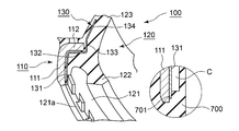
- FIG. 1 is a schematic cross-sectional view of a dust seal according to Embodiment 1 of the present invention.
- FIG. 2 is a schematic cross-sectional view of a sealing structure to which the dust seal according to the first embodiment of the present invention is applied.
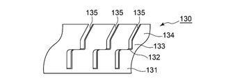
- FIG. 3 is a part of a perspective view of a pressing member provided in the dust seal according to the first embodiment of the present invention.
- FIG. 4 is a partially broken perspective view of the dust seal according to the first embodiment of the present invention.
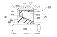
- FIG. 5 is a schematic cross-sectional view of a sealing structure to which a dust seal according to Example 2 of the present invention is applied.
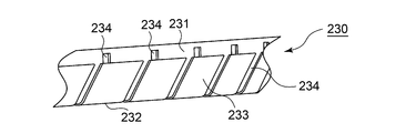
- FIG. 6 is a part of a perspective view of a pressing member provided in a dust seal according to Embodiment 2 of the present invention.
- Example 1 A dust seal according to Embodiment 1 of the present invention will be described with reference to FIGS.
- the dust seal according to the embodiment of the present invention can be used for a hydraulic cylinder provided in a construction machine, an automobile shock absorber, a damper, a general industrial device, and the like.
- the sealing structure to which the dust seal according to the present embodiment is applied includes a shaft, a housing, and a dust seal that seals an annular gap between the shaft and the housing.
- the dust seal is preferably used when the shaft and the housing move relative to each other.
- the relative movement between the shaft and the housing includes the case where the two or more movements are performed in combination when the reciprocating movement is relatively relative, the relative rotation is performed, or the relative swinging is performed. It is.
- FIG. 1 is a schematic cross-sectional view of a dust seal according to Embodiment 1 of the present invention.
- the dust seal according to the present embodiment has a rotationally symmetric shape except for a part of the configuration, and FIG. 1 shows a cross-sectional view of the dust seal taken along a plane including the central axis of the dust seal.
- FIG. 2 is a schematic cross-sectional view of a sealing structure to which the dust seal according to the first embodiment of the present invention is applied. 2 also shows a cross-sectional view of the dust seal or the like cut along a plane including the center axis of the dust seal.
- FIG. 3 is a part of a perspective view of a pressing member provided in the dust seal according to the first embodiment of the present invention.
- FIG. 4 is a partially broken perspective view of the dust seal according to the first embodiment of the present invention, and shows a part of a perspective view of the dust seal cut along a plane including the central axis.
- the sealing structure according to the present embodiment includes a housing 600 having a shaft hole, a shaft 500 inserted through the shaft hole, and a dust seal 100. An annular gap between the shaft 500 and the housing 600 is sealed by the dust seal 100.
- the left side is a sealed region side (O) in which a fluid to be sealed (for example, oil) is sealed, and the right side is a side opposite to the sealed region (atmosphere side (A)).
- the dust seal 100 according to the present embodiment will be described in more detail with reference to FIGS.
- the dust seal 100 according to the present embodiment includes a metal reinforcing ring 110, an elastic seal body 120 provided integrally with the reinforcing ring 110, and a metal ring embedded in the seal body 120.
- the pressing member (spring) 130 is provided. Note that the dust seal 100 can be obtained by molding the seal body 120 by insert molding (injection molding) using the reinforcing ring 110 and the pressing member 130 as insert parts.
- the seal body 120 is made of polyurethane elastomer or rubber.
- the reinforcing ring 110 includes an annular portion 111 and an inward flange portion 112 provided at an end portion of the annular portion 111.
- the annular portion 111 according to the present embodiment has a cylindrical shape.
- the annular seal 111 is fitted to the inner peripheral surface of the shaft hole of the housing 600, whereby the dust seal 100 is fixed to the housing 600.
- the seal body 120 includes an annular portion 121, a main lip 122, and a dust lip 123.
- the annular portion 121 is provided on the inner peripheral surface side of the annular portion 111 in the reinforcing ring 110.
- the main lip 122 extends from the atmosphere side (A) to the sealed region side (O) and radially inward, and is configured to be in close contact with the shaft 500.
- the dust lip 123 is provided on the atmosphere side (A) with respect to the main lip 122, and extends from the sealing region side (O) to the atmosphere side (A) and radially inward, so as to be in close contact with the shaft 500.
- the tip end of the main lip 122 and the tip end of the dust lip 123 slide while maintaining a state in close contact with the outer peripheral surface of the shaft 500.
- the pressing member 130 includes a first annular portion 131 provided along the inside of the annular portion 111 in the reinforcing ring 110, an inward flange portion 132 provided along the inward flange portion 112 in the reinforcing ring 110, and an inward flange. And a second annular portion 133 provided along the tip of the portion 112.
- the pressing member 130 has a pressing portion 134 that extends from the tip of the second annular portion 133 toward the atmosphere side (A) and radially inward, and presses the dust lip 123 radially inward.
- a concave portion 121 a is provided on the inner peripheral surface side of the annular portion 121 in the seal body 120 on the radially inner side of the first annular portion 131 in the pressing member 130.
- the recessed part 121a is provided with two or more at intervals in the circumferential direction. These recesses 121 a are provided for positioning the pressing member 130 with respect to the reinforcing ring 110 by a molding die that integrally molds the seal body 120 with respect to the reinforcing ring 110. This point will be described with reference to FIG.
- FIG. 4 is a part of a sectional view when the reinforcing ring 110 and the pressing member 130 are set with respect to the molding die 700 (the end of the annular portion 111 and the pressing member 130 in the reinforcing ring 110). The vicinity of the end of the first annular portion 131 in FIG.
- the reinforcing ring 110 and the pressing member 130 are set in a state in which they are overlapped.
- the second annular portion 133 of the pressing member 130 are in close contact with each other.
- the pressing member 701 provided in the molding die 700 keeps the pressing member 130 positioned with respect to the reinforcing ring 110 even during molding.
- C indicates a cavity.
- a portion of the cavity C shown in a circle in FIG. 4 corresponds to a portion where the annular portion 121 in the seal body 120 is formed.
- the recessed part 121a is formed of the site
- FIG. 7 In a state where the reinforcing ring 110 and the pressing member 130 are set with respect to the molding die 700, the pressing portion 701 in the molding die 700 is in contact with a part of the first annular portion 131 in the pressing member 130. Yes. Thereby, the state in which the reinforcing ring 110 and the pressing member 130 are positioned in the molding die 700 is maintained.
- the pressing member 130 is provided with a plurality of through portions 135 penetrating the front and back.
- the penetrating portion 135 is configured by a slit that extends in parallel with the central axis from the end portion on the pressing portion 134 side of the pressing member 130 to the vicinity of the end portion on the first annular portion 131 side.
- the material of the seal body 120 can pass through the through portions 135 when insert molding is performed.
- the pressing member 130 includes a first annular portion 131 provided along the inside of the annular portion 111 in the reinforcing ring 110 and an inward flange provided along the inward flange portion 112 in the reinforcing ring 110. It has a portion 132. Thereby, even when the seal body 120 is integrally formed with the reinforcing ring 110, the positioning accuracy of the pressing member 130 with respect to the reinforcing ring 110 can be increased.
- the seal body 120 is pressed against the reinforcing ring 110 by a molding die 700 that integrally molds the seal body 120 with respect to the reinforcing ring 110 inside the annular portion 131 of the pressing member 130 in the radial direction.
- a recess 121a for positioning is provided.
- the pressing member 130 is provided with a plurality of through portions 135 penetrating the front and back. Therefore, when the seal body 120 is integrally molded with the reinforcing ring 110, the flow resistance of the molding material against the pressing member 130 is suppressed when the molding material for molding the seal body 120 flows during molding. Can be made. Thereby, the positioning accuracy of the pressing member 130 with respect to the reinforcing ring 110 can be further enhanced.
- FIG. 5 is a schematic cross-sectional view of a sealing structure to which a dust seal according to Example 2 of the present invention is applied.
- the dust seal according to the present embodiment also has a rotationally symmetric shape except for a part of the configuration, and
- FIG. 5 shows a sectional view of the dust seal cut along a plane including the central axis of the dust seal.
- FIG. 6 is a part of a perspective view of a pressing member provided in a dust seal according to Embodiment 2 of the present invention.
- the sealing structure includes a housing 600 having a shaft hole, a shaft 500 inserted through the shaft hole, and a dust seal 200. An annular gap between the shaft 500 and the housing 600 is sealed by the dust seal 200.
- the left side is a sealed region side (O) in which a fluid to be sealed (for example, oil) is sealed, and the right side is a side opposite to the sealed region (atmosphere side (A)).
- the dust seal 200 which concerns on a present Example is demonstrated in detail.
- the dust seal 200 includes a metal reinforcing ring 210, an elastic seal body 220 provided integrally with the reinforcing ring 210, and a metal ring embedded in the seal body 220.
- the pressing member (spring) 230 is provided.
- the dust seal 200 is obtained by molding the seal body 220 by insert molding (injection molding) using the reinforcing ring 210 and the pressing member 230 as insert parts.
- the seal body 220 is made of polyurethane elastomer or rubber.
- the reinforcing ring 210 includes an annular portion 211 and an inward flange portion 212 provided at the end of the annular portion 211.
- the annular portion 211 according to the present embodiment has a cylindrical shape.
- the dust seal 200 is fixed to the housing 600 by fitting the annular portion 211 to the inner peripheral surface of the shaft hole of the housing 600.
- the seal body 220 includes an annular portion 221 and a dust lip 222.
- the annular portion 221 is provided on the inner peripheral surface side of the annular portion 211 in the reinforcing ring 210.
- the dust lip 222 extends from the sealed region side (O) to the atmosphere side (A) and radially inward, and is configured to be in close contact with the shaft 500. When the shaft 500 and the housing 600 move relative to each other, the dust lip 222 slides while maintaining the state where the tip of the dust lip 222 is in close contact with the outer peripheral surface of the shaft 500.
- the pressing member 230 has an annular portion 231 provided along the inner side of the annular portion 211 in the reinforcing ring 210 and an inward flange portion 232 provided along the inward flange portion 212 in the reinforcing ring 210.
- the pressing member 230 has a pressing portion 233 that extends from the tip of the inward flange portion 232 toward the atmosphere side (A) and radially inward, and presses the dust lip 222 radially inward.
- a concave portion 221 a is provided on the inner peripheral surface side of the annular portion 221 in the seal body 220 on the radially inner side of the annular portion 231 of the pressing member 230.
- the recessed part 221a is provided with two or more at intervals in the circumferential direction. These recesses 221 a are provided for positioning the pressing member 230 with respect to the reinforcing ring 210 by a molding die for integrally molding the seal body 220 with respect to the reinforcing ring 210. This point is as described in the first embodiment.
- a plurality of through portions 234 penetrating the front and back are provided.
- the penetrating portion 234 is constituted by a slit that extends in parallel to the central axis from the end portion on the pressing portion 233 side of the pressing member 230 and extends to the vicinity of the end portion on the annular portion 231 side.
- the present invention is also applicable to a dust seal not provided with a reinforcing ring. That is, a metal pressing member that presses the dust lip radially inward can be provided inside an elastic seal body that does not include a reinforcing ring.
- the pressing member in order to position the pressing member, the pressing member is positioned with respect to the reinforcing ring (the pressing member has a shape portion along the reinforcing ring, and a recess is provided in the seal body.
- the configuration has been described as an example. However, in the case where another configuration for positioning the pressing member inside the seal body of the dust seal can be employed, the above configuration may not be employed.
Landscapes
- Engineering & Computer Science (AREA)
- General Engineering & Computer Science (AREA)
- Mechanical Engineering (AREA)
- Manufacturing & Machinery (AREA)
- Sealing With Elastic Sealing Lips (AREA)
- Sealing Devices (AREA)
Abstract
金属製の押圧部材の機能の低下の抑制を図ることのできるダストシールを提供する。 軸500とハウジング600との間の環状隙間を封止するダストシール100において、軸500に密着するダストリップ123を有する弾性体製のシール本体120と、シール本体120の内部に埋め込まれ、ダストリップ123を径方向内側に押圧する金属製の押圧部材130と、を備えることを特徴とする。
Description
本発明は、軸とハウジングとの間の環状隙間を封止するダストシールに関する。
油圧シリンダなどの各種機器においては、外部から機器内部への異物の侵入を抑制するためにダストシールが設けられている。ダストシールにおけるシール本体は、ポリウレタンエラストマーやゴムなどの弾性体により構成されている。弾性体単体の場合には、長期使用によりヘタリ(塑性変形)が生じることによって、シール性が低下してしまう。そのため、シール本体に設けられているダストリップを径方向内側に向けて押圧するための押圧部材(金属バネ)が設けられる技術が知られている(特許文献1参照)。
しかしながら、このような技術においては、押圧部材に対してダスト(泥水など)が付着して固まるなどにより、押圧機能が発揮されなくなるおそれがある。また、ダストに含まれている塩分や金属粉によって、金属製の押圧部材に錆びや電食が生じて機能が低下するおそれもある。
本発明の目的は、金属製の押圧部材の機能の低下の抑制を図ることのできるダストシールを提供することにある。
本発明は、上記課題を解決するために以下の手段を採用した。
すなわち、本発明のダストシールは、
軸とハウジングとの間の環状隙間を封止するダストシールにおいて、
前記軸に密着するダストリップを有する弾性体製のシール本体と、
前記シール本体の内部に埋め込まれ、前記ダストリップを径方向内側に押圧する金属製の押圧部材と、
を備えることを特徴とする。
軸とハウジングとの間の環状隙間を封止するダストシールにおいて、
前記軸に密着するダストリップを有する弾性体製のシール本体と、
前記シール本体の内部に埋め込まれ、前記ダストリップを径方向内側に押圧する金属製の押圧部材と、
を備えることを特徴とする。
本発明によれば、金属製の押圧部材は、シール本体の内部に埋め込まれているため、ダスト(異物)が押圧部材に付着することはない。
前記ダストリップは、密封領域側から密封領域とは反対側かつ径方向内側に向かって伸びるように設けられると共に、
前記押圧部材は、前記ダストリップの内部で、密封領域側から密封領域とは反対側かつ径方向内側に向かって伸び、前記ダストリップを径方向内側に押圧する押圧部分を有することを特徴とする。
前記押圧部材は、前記ダストリップの内部で、密封領域側から密封領域とは反対側かつ径方向内側に向かって伸び、前記ダストリップを径方向内側に押圧する押圧部分を有することを特徴とする。
このように、押圧部材に設けられた押圧部分によって、ダストリップを径方向内側に押圧させることができる。
環状部、及び該環状部の端部に設けられる内向きフランジ部を有する補強環と、
該補強環に対して一体的に設けられる前記シール本体と、
を備えると共に、
前記押圧部材は、前記環状部の内側に沿って設けられる環状部分、及び前記内向きフランジ部に沿って設けられる内向きフランジ部分を有するとよい。
該補強環に対して一体的に設けられる前記シール本体と、
を備えると共に、
前記押圧部材は、前記環状部の内側に沿って設けられる環状部分、及び前記内向きフランジ部に沿って設けられる内向きフランジ部分を有するとよい。
これにより、補強環に対してシール本体が一体成形される場合においても、補強環に対する押圧部材の位置決め精度を高めることができる。
前記シール本体には、前記環状部分の径方向内側に、前記補強環に対して前記シール本体を一体成形する成形金型によって、前記押圧部材を補強環に対して位置決めするための凹部が設けられているとよい。
これにより、補強環に対してシール本体が一体成形される場合においても、補強環に対する押圧部材の位置決め精度をより一層高めることができる。
前記押圧部材には、表裏を貫通する貫通部が複数設けられているとよい。
これにより、補強環に対してシール本体が一体成形される場合に、シール本体を成形するための成形材料が、成形時に流動する際に、押圧部材に対する成形材料の流動抵抗を抑制させることができる。これにより、補強環に対する押圧部材の位置決め精度をより一層高めることができる。
なお、上記各構成は、可能な限り組み合わせて採用し得る。
以上説明したように、本発明によれば、金属製の押圧部材の機能の低下の抑制を図ることができる。
以下に図面を参照して、この発明を実施するための形態を、実施例に基づいて例示的に詳しく説明する。ただし、この実施例に記載されている構成部品の寸法、材質、形状、その相対配置などは、特に特定的な記載がない限りは、この発明の範囲をそれらのみに限定する趣旨のものではない。
(実施例1)
図1~図4を参照して、本発明の実施例1に係るダストシールについて説明する。なお、本発明の実施例に係るダストシールは、建設機械に備えられる油圧シリンダ,自動車用のショックアブソーバ,ダンパ,一般産業機器などに用いることができる。また、本実施例に係るダストシールが適用される密封構造は、軸と、ハウジングと、これら軸とハウジングとの間の環状隙間を封止するダストシールとにより構成される。また、ダストシールは、軸とハウジングが相対的に移動する場合に好適に用いられる。軸とハウジングとの相対的な移動については、相対的に往復動する場合、相対的に回転する場合、相対的に揺動する場合、これら2つ以上の運動が複合的に行われる場合が含まれる。
図1~図4を参照して、本発明の実施例1に係るダストシールについて説明する。なお、本発明の実施例に係るダストシールは、建設機械に備えられる油圧シリンダ,自動車用のショックアブソーバ,ダンパ,一般産業機器などに用いることができる。また、本実施例に係るダストシールが適用される密封構造は、軸と、ハウジングと、これら軸とハウジングとの間の環状隙間を封止するダストシールとにより構成される。また、ダストシールは、軸とハウジングが相対的に移動する場合に好適に用いられる。軸とハウジングとの相対的な移動については、相対的に往復動する場合、相対的に回転する場合、相対的に揺動する場合、これら2つ以上の運動が複合的に行われる場合が含まれる。
図1は本発明の実施例1に係るダストシールの模式的断面図である。なお、本実施例に係るダストシールは、一部の構成を除き回転対称形状であり、図1においては、ダストシールの中心軸線を含む面でダストシールを切断した断面図を示している。図2は本発明の実施例1に係るダストシールが適用された密封構造の模式的断面図である。図2においても、ダストシールの中心軸線を含む面でダストシール等を切断した断面図を示している。図3は本発明の実施例1に係るダストシールに備えられる押圧部材の斜視図の一部である。図4は本発明の実施例1に係るダストシールの一部破断斜視図であり、ダストシールを上記の中心軸線を含む面で切断した斜視図の一部を示している。
<密封構造>
図2を参照して、本実施例に係るダストシールが適用される密封構造について説明する。本実施例に係る密封構造は、軸孔を有するハウジング600と、軸孔に挿通される軸500と、ダストシール100とを備えている。ダストシール100によって、軸500とハウジング600との間の環状隙間が封止される。図2中、左側が、密封対象流体(例えば、オイル)が密封されている密封領域側(O)であり、右側が、密封領域とは反対側(大気側(A))である。
図2を参照して、本実施例に係るダストシールが適用される密封構造について説明する。本実施例に係る密封構造は、軸孔を有するハウジング600と、軸孔に挿通される軸500と、ダストシール100とを備えている。ダストシール100によって、軸500とハウジング600との間の環状隙間が封止される。図2中、左側が、密封対象流体(例えば、オイル)が密封されている密封領域側(O)であり、右側が、密封領域とは反対側(大気側(A))である。
<ダストシール>
図1~図4を参照して、本実施例に係るダストシール100について、より詳細に説明する。本実施例に係るダストシール100は、金属製の補強環110と、補強環110に対して一体的に設けられる弾性体製のシール本体120と、シール本体120の内部に埋め込まれた金属製の環状の押圧部材(スプリング)130とを備えている。なお、補強環110と押圧部材130をインサート部品として、インサート成形(射出成形)によってシール本体120を成形することによりダストシール100が得られる。シール本体120は、ポリウレタンエラストマーまたはゴムなどにより構成される。
図1~図4を参照して、本実施例に係るダストシール100について、より詳細に説明する。本実施例に係るダストシール100は、金属製の補強環110と、補強環110に対して一体的に設けられる弾性体製のシール本体120と、シール本体120の内部に埋め込まれた金属製の環状の押圧部材(スプリング)130とを備えている。なお、補強環110と押圧部材130をインサート部品として、インサート成形(射出成形)によってシール本体120を成形することによりダストシール100が得られる。シール本体120は、ポリウレタンエラストマーまたはゴムなどにより構成される。
補強環110は、環状部111と、環状部111の端部に設けられる内向きフランジ部112とから構成される。本実施例に係る環状部111は円筒形状である。この環状部111が、ハウジング600の軸孔の内周面に嵌合されることにより、ダストシール100はハウジング600に固定される。
シール本体120は、環状部121と、メインリップ122と、ダストリップ123とを備えている。環状部121は、補強環110における環状部111の内周面側に設けられる。メインリップ122は、大気側(A)から密封領域側(O)かつ径方向内側に向かって伸び、軸500に密着するように構成されている。ダストリップ123は、メインリップ122よりも大気側(A)に設けられており、密封領域側(O)から大気側(A)かつ径方向内側に向かって伸び、軸500に密着するように構成されている。軸500とハウジング600が相対的に移動する場合には、メインリップ122の先端とダストリップ123の先端が軸500の外周面に対して密着した状態を維持しつつ摺動する。
押圧部材130は、補強環110における環状部111の内側に沿って設けられる第1環状部分131と、補強環110における内向きフランジ部112に沿って設けられる内向きフランジ部分132と、内向きフランジ部112の先端に沿って設けられる第2環状部分133とを有している。また、押圧部材130は、この第2環状部分133の先端から大気側(A)かつ径方向内側に向かって伸び、ダストリップ123を径方向内側に押圧する押圧部分134を有している。
また、シール本体120における環状部121の内周面側には、押圧部材130における第1環状部分131の径方向内側に、凹部121aが設けられている。なお、凹部121aは、周方向に間隔を空けて複数設けられている。これらの凹部121aは、補強環110に対してシール本体120を一体成形する成形金型によって、押圧部材130を補強環110に対して位置決めするために設けられている。この点について、図4を参照して説明する。図4中の丸の中には、成形金型700に対して、補強環110と押圧部材130をセットした際の断面図の一部(補強環110における環状部111の端部と押圧部材130における第1環状部分131の端部の付近)を示している。成形金型700に対しては、補強環110と押圧部材130は、これらが重なった状態でセットされる。このとき、補強環110の環状部111と押圧部材130の第1環状部分131、補強環110の内向きフランジ部112と押圧部材130の内向きフランジ部分132、補強環110の内向きフランジ部112の先端と押圧部材130の第2環状部分133は、それぞれ密着した状態となる。そして、成形金型700に設けられた押え部701によって、成形時においても、押圧部材130は、補強環110に対して位置決めされた状態が保たれる。
図4中、Cはキャビティを示している。キャビティCのうち図4の丸の中に示された部分は、シール本体120における環状部121が成形される部位に相当する。そして、押え部701に相当する部位により、凹部121aが形成される。成形金型700に対して、補強環110と押圧部材130をセットした状態においては、成形金型700における押え部701が押圧部材130における第1環状部分131の一部に接した状態となっている。これにより、補強環110と押圧部材130は成形金型700内で位置決めされた状態が保たれる。
また、押圧部材130には、表裏を貫通する貫通部135が複数設けられている。本実施例においては、押圧部材130における押圧部分134側の端部から、中心軸線に平行に伸び、かつ第1環状部分131側の端部付近まで伸びるスリットにより貫通部135が構成されている。このように、複数の貫通部135が設けられていることにより、インサート成形が行われる際には、シール本体120の材料は貫通部135を通り抜けることができる。
<本実施例に係るダストシールの優れた点>
本実施例に係るダストシール100によれば、金属製の押圧部材130は、シール本体120の内部に埋め込まれているため、ダスト(異物)が押圧部材130(少なくとも押圧部分134)に付着することはない。従って、押圧部材130に対してダスト(泥水など)が付着して、押圧機能が発揮されなくなるおそれはない。また、ダストに含まれている塩分や金属粉によって、押圧部材130に錆びや電食が生じて機能が低下してしまうこともない。以上より、金属製の押圧部材130の機能の低下の抑制を図ることができる。
本実施例に係るダストシール100によれば、金属製の押圧部材130は、シール本体120の内部に埋め込まれているため、ダスト(異物)が押圧部材130(少なくとも押圧部分134)に付着することはない。従って、押圧部材130に対してダスト(泥水など)が付着して、押圧機能が発揮されなくなるおそれはない。また、ダストに含まれている塩分や金属粉によって、押圧部材130に錆びや電食が生じて機能が低下してしまうこともない。以上より、金属製の押圧部材130の機能の低下の抑制を図ることができる。
また、本実施例に係る押圧部材130は、補強環110における環状部111の内側に沿って設けられる第1環状部分131、及び補強環110における内向きフランジ部112に沿って設けられる内向きフランジ部分132を有している。これにより、補強環110に対してシール本体120が一体成形される場合においても、補強環110に対する押圧部材130の位置決め精度を高めることができる。
また、シール本体120には、押圧部材130における環状部分131の径方向内側に、補強環110に対してシール本体120を一体成形する成形金型700によって、押圧部材130を補強環110に対して位置決めするための凹部121aが設けられている。これにより、補強環110に対してシール本体120が一体成形される場合においても、補強環110に対する押圧部材130の位置決め精度をより一層高めることができる。なお、凹部121aが設けられている部分では、押圧部材130が露出する可能性がある。しかしながら、当該部分にダストが付着しても、押圧部材130による押圧機能には殆ど影響しない。
更に、押圧部材130には、表裏を貫通する貫通部135が複数設けられている。これにより、補強環110に対してシール本体120が一体成形される場合に、シール本体120を成形するための成形材料が、成形時に流動する際に、押圧部材130に対する成形材料の流動抵抗を抑制させることができる。これにより、補強環110に対する押圧部材130の位置決め精度をより一層高めることができる。
(実施例2)
図5及び図6には、本発明の実施例2が示されている。本実施例に係るダストシール200が適用される密封構造や用途については、実施例1の場合と同様である。図5は本発明の実施例2に係るダストシールが適用された密封構造の模式的断面図である。本実施例に係るダストシールについても、一部の構成を除き回転対称形状であり、図5においては、ダストシールの中心軸線を含む面でダストシールを切断した断面図を示している。図6は本発明の実施例2に係るダストシールに備えられる押圧部材の斜視図の一部である。
図5及び図6には、本発明の実施例2が示されている。本実施例に係るダストシール200が適用される密封構造や用途については、実施例1の場合と同様である。図5は本発明の実施例2に係るダストシールが適用された密封構造の模式的断面図である。本実施例に係るダストシールについても、一部の構成を除き回転対称形状であり、図5においては、ダストシールの中心軸線を含む面でダストシールを切断した断面図を示している。図6は本発明の実施例2に係るダストシールに備えられる押圧部材の斜視図の一部である。
<密封構造>
図5を参照して、本実施例に係るダストシールが適用される密封構造について説明する。本実施例に係る密封構造は、軸孔を有するハウジング600と、軸孔に挿通される軸500と、ダストシール200とを備えている。ダストシール200によって、軸500とハウジング600との間の環状隙間が封止される。図5中、左側が、密封対象流体(例えば、オイル)が密封されている密封領域側(O)であり、右側が、密封領域とは反対側(大気側(A))である。
図5を参照して、本実施例に係るダストシールが適用される密封構造について説明する。本実施例に係る密封構造は、軸孔を有するハウジング600と、軸孔に挿通される軸500と、ダストシール200とを備えている。ダストシール200によって、軸500とハウジング600との間の環状隙間が封止される。図5中、左側が、密封対象流体(例えば、オイル)が密封されている密封領域側(O)であり、右側が、密封領域とは反対側(大気側(A))である。
<ダストシール>
図5及び図6を参照して、本実施例に係るダストシール200について、より詳細に説明する。本実施例に係るダストシール200は、金属製の補強環210と、補強環210に対して一体的に設けられる弾性体製のシール本体220と、シール本体220の内部に埋め込まれた金属製の環状の押圧部材(スプリング)230とを備えている。なお、補強環210と押圧部材230をインサート部品として、インサート成形(射出成形)によってシール本体220を成形することによりダストシール200が得られる。シール本体220は、ポリウレタンエラストマーまたはゴムなどにより構成される。
図5及び図6を参照して、本実施例に係るダストシール200について、より詳細に説明する。本実施例に係るダストシール200は、金属製の補強環210と、補強環210に対して一体的に設けられる弾性体製のシール本体220と、シール本体220の内部に埋め込まれた金属製の環状の押圧部材(スプリング)230とを備えている。なお、補強環210と押圧部材230をインサート部品として、インサート成形(射出成形)によってシール本体220を成形することによりダストシール200が得られる。シール本体220は、ポリウレタンエラストマーまたはゴムなどにより構成される。
補強環210は、環状部211と、環状部211の端部に設けられる内向きフランジ部212とから構成される。本実施例に係る環状部211は円筒形状である。この環状部211が、ハウジング600の軸孔の内周面に嵌合されることにより、ダストシール200はハウジング600に固定される。
シール本体220は、環状部221と、ダストリップ222とを備えている。環状部221は、補強環210における環状部211の内周面側に設けられる。ダストリップ222は、密封領域側(O)から大気側(A)かつ径方向内側に向かって伸び、軸500に密着するように構成されている。軸500とハウジング600が相対的に移動する場合には、ダストリップ222の先端が軸500の外周面に対して密着した状態を維持しつつ摺動する。
押圧部材230は、補強環210における環状部211の内側に沿って設けられる環状部分231と、補強環210における内向きフランジ部212に沿って設けられる内向きフランジ部分232とを有している。また、押圧部材230は、この内向きフランジ部分232の先端から大気側(A)かつ径方向内側に向かって伸び、ダストリップ222を径方向内側に押圧する押圧部分233を有している。
また、シール本体220における環状部221の内周面側には、押圧部材230における環状部分231の径方向内側に、凹部221aが設けられている。なお、凹部221aは、周方向に間隔を空けて複数設けられている。これらの凹部221aは、補強環210に対してシール本体220を一体成形する成形金型によって、押圧部材230を補強環210に対して位置決めするために設けられている。この点については、実施例1で説明した通りである。
本実施例に係る押圧部材230においても、表裏を貫通する貫通部234が複数設けられている。本実施例においては、押圧部材230における押圧部分233側の端部から、中心軸線に平行に伸び、かつ環状部分231側の端部付近まで伸びるスリットにより貫通部234が構成されている。このように、複数の貫通部234が設けられていることにより、インサート成形が行われる際には、シール本体220の材料は貫通部234を通り抜けることができる。
以上のように構成される本実施例に係るダストシール200においても、上記実施例1の場合と同様の効果を得ることができる。
(その他)
上記各実施例においては、補強環を備えるダストシールの場合を例にして説明したが、本発明においては、補強環を備えていないダストシールにも適用可能である。つまり、補強環を備えていない弾性体製のシール本体の内部に、ダストリップを径方向内側に押圧する金属製の押圧部材を設けることができる。また、上記各実施例においては、押圧部材を位置決めするために、補強環に対して押圧部材を位置決めさせる構成(押圧部材が補強環に沿う形状部を備える構成とし、かつシール本体に凹部を設ける構成)を設ける場合を例にして説明した。しかしながら、ダストシールのシール本体の内部に押圧部材を位置決めさせるための他の構成を採用可能な場合には、上記のような構成を採用しなくてもよい。
上記各実施例においては、補強環を備えるダストシールの場合を例にして説明したが、本発明においては、補強環を備えていないダストシールにも適用可能である。つまり、補強環を備えていない弾性体製のシール本体の内部に、ダストリップを径方向内側に押圧する金属製の押圧部材を設けることができる。また、上記各実施例においては、押圧部材を位置決めするために、補強環に対して押圧部材を位置決めさせる構成(押圧部材が補強環に沿う形状部を備える構成とし、かつシール本体に凹部を設ける構成)を設ける場合を例にして説明した。しかしながら、ダストシールのシール本体の内部に押圧部材を位置決めさせるための他の構成を採用可能な場合には、上記のような構成を採用しなくてもよい。
100,200 ダストシール
110,210 補強環
111,211 環状部
112,212 内向きフランジ部
120,220 シール本体
121,221 環状部
121a,221a 凹部
122 メインリップ
123,222 ダストリップ
130,230 押圧部材
131 第1環状部分
231 環状部分
132,232 内向きフランジ部分
133 第2環状部分
134,233 押圧部分
135,234 貫通部
500 軸
600 ハウジング
700 成形金型
701 押え部
C キャビティ
110,210 補強環
111,211 環状部
112,212 内向きフランジ部
120,220 シール本体
121,221 環状部
121a,221a 凹部
122 メインリップ
123,222 ダストリップ
130,230 押圧部材
131 第1環状部分
231 環状部分
132,232 内向きフランジ部分
133 第2環状部分
134,233 押圧部分
135,234 貫通部
500 軸
600 ハウジング
700 成形金型
701 押え部
C キャビティ
Claims (5)
- 軸とハウジングとの間の環状隙間を封止するダストシールにおいて、
前記軸に密着するダストリップを有する弾性体製のシール本体と、
前記シール本体の内部に埋め込まれ、前記ダストリップを径方向内側に押圧する金属製の押圧部材と、
を備えることを特徴とするダストシール。 - 前記ダストリップは、密封領域側から密封領域とは反対側かつ径方向内側に向かって伸びるように設けられると共に、
前記押圧部材は、前記ダストリップの内部で、密封領域側から密封領域とは反対側かつ径方向内側に向かって伸び、前記ダストリップを径方向内側に押圧する押圧部分を有することを特徴とする請求項1に記載のダストシール。 - 環状部、及び該環状部の端部に設けられる内向きフランジ部を有する補強環と、
該補強環に対して一体的に設けられる前記シール本体と、
を備えると共に、
前記押圧部材は、前記環状部の内側に沿って設けられる環状部分、及び前記内向きフランジ部に沿って設けられる内向きフランジ部分を有することを特徴とする請求項1または2に記載のダストシール。 - 前記シール本体には、前記環状部分の径方向内側に、前記補強環に対して前記シール本体を一体成形する成形金型によって、前記押圧部材を補強環に対して位置決めするための凹部が設けられていることを特徴とする請求項3に記載のダストシール。
- 前記押圧部材には、表裏を貫通する貫通部が複数設けられていることを特徴とする請求項1~4のいずれか一つに記載のダストシール。
Priority Applications (1)
| Application Number | Priority Date | Filing Date | Title |
|---|---|---|---|
| JP2018518672A JP6365806B1 (ja) | 2016-11-28 | 2017-11-21 | ダストシール |
Applications Claiming Priority (2)
| Application Number | Priority Date | Filing Date | Title |
|---|---|---|---|
| JP2016-229875 | 2016-11-28 | ||
| JP2016229875 | 2016-11-28 |
Publications (1)
| Publication Number | Publication Date |
|---|---|
| WO2018097119A1 true WO2018097119A1 (ja) | 2018-05-31 |
Family
ID=62195024
Family Applications (1)
| Application Number | Title | Priority Date | Filing Date |
|---|---|---|---|
| PCT/JP2017/041763 Ceased WO2018097119A1 (ja) | 2016-11-28 | 2017-11-21 | ダストシール |
Country Status (2)
| Country | Link |
|---|---|
| JP (1) | JP6365806B1 (ja) |
| WO (1) | WO2018097119A1 (ja) |
Citations (8)
| Publication number | Priority date | Publication date | Assignee | Title |
|---|---|---|---|---|
| JPS5442853U (ja) * | 1977-08-30 | 1979-03-23 | ||
| JPH01165367U (ja) * | 1988-05-12 | 1989-11-20 | ||
| JP2009058051A (ja) * | 2007-08-31 | 2009-03-19 | Nok Corp | 往復動軸用密封装置 |
| JP2014126105A (ja) * | 2012-12-26 | 2014-07-07 | Nsk Ltd | 車輪支持用転がり軸受ユニット |
| JP2014167314A (ja) * | 2013-02-28 | 2014-09-11 | Kayaba Ind Co Ltd | シール部材及びシール部材を備えるフロントフォーク |
| WO2016027590A1 (ja) * | 2014-08-21 | 2016-02-25 | Nok株式会社 | ダストカバー |
| JP2016044737A (ja) * | 2014-08-22 | 2016-04-04 | Thkリズム株式会社 | ボールジョイント |
| WO2016080203A1 (ja) * | 2014-11-18 | 2016-05-26 | Nok株式会社 | 密封構造 |
-
2017
- 2017-11-21 WO PCT/JP2017/041763 patent/WO2018097119A1/ja not_active Ceased
- 2017-11-21 JP JP2018518672A patent/JP6365806B1/ja active Active
Patent Citations (8)
| Publication number | Priority date | Publication date | Assignee | Title |
|---|---|---|---|---|
| JPS5442853U (ja) * | 1977-08-30 | 1979-03-23 | ||
| JPH01165367U (ja) * | 1988-05-12 | 1989-11-20 | ||
| JP2009058051A (ja) * | 2007-08-31 | 2009-03-19 | Nok Corp | 往復動軸用密封装置 |
| JP2014126105A (ja) * | 2012-12-26 | 2014-07-07 | Nsk Ltd | 車輪支持用転がり軸受ユニット |
| JP2014167314A (ja) * | 2013-02-28 | 2014-09-11 | Kayaba Ind Co Ltd | シール部材及びシール部材を備えるフロントフォーク |
| WO2016027590A1 (ja) * | 2014-08-21 | 2016-02-25 | Nok株式会社 | ダストカバー |
| JP2016044737A (ja) * | 2014-08-22 | 2016-04-04 | Thkリズム株式会社 | ボールジョイント |
| WO2016080203A1 (ja) * | 2014-11-18 | 2016-05-26 | Nok株式会社 | 密封構造 |
Also Published As
| Publication number | Publication date |
|---|---|
| JPWO2018097119A1 (ja) | 2018-11-22 |
| JP6365806B1 (ja) | 2018-08-01 |
Similar Documents
| Publication | Publication Date | Title |
|---|---|---|
| JP6067274B2 (ja) | ボールジョイント用ダストカバー | |
| CN107407420B (zh) | 密封装置 | |
| CN105745477A (zh) | 密封装置的制造方法 | |
| JP5931453B2 (ja) | 転がり軸受 | |
| JP2013177957A (ja) | ボールジョイント用ダストカバー | |
| JP2018035855A (ja) | 密封装置 | |
| JP7183044B2 (ja) | 密封装置 | |
| CN105765243A (zh) | 球窝接头用防尘罩 | |
| JP6366003B2 (ja) | 密封装置 | |
| JP3192748U (ja) | 密封装置 | |
| JP6365806B1 (ja) | ダストシール | |
| JP6610673B2 (ja) | ダストシール | |
| JP2010242823A (ja) | 密封装置 | |
| JP6262961B2 (ja) | 密封装置 | |
| WO2014181672A1 (ja) | ボールジョイント用ダストカバー | |
| JP6868386B2 (ja) | 密封装置 | |
| JP6625340B2 (ja) | 密封装置 | |
| JP2022070382A (ja) | 密封装置 | |
| JP2005325924A (ja) | 密封装置 | |
| JP3204289U (ja) | 密封装置 | |
| JP5936064B2 (ja) | ボールジョイント用ダストカバー | |
| CN213271013U (zh) | 密封装置及密封结构 | |
| JP7224248B2 (ja) | 密封装置 | |
| JP6600151B2 (ja) | 密封装置 | |
| JP2010223410A (ja) | アブソーバ用シール |
Legal Events
| Date | Code | Title | Description |
|---|---|---|---|
| ENP | Entry into the national phase |
Ref document number: 2018518672 Country of ref document: JP Kind code of ref document: A |
|
| 121 | Ep: the epo has been informed by wipo that ep was designated in this application |
Ref document number: 17873867 Country of ref document: EP Kind code of ref document: A1 |
|
| NENP | Non-entry into the national phase |
Ref country code: DE |
|
| 122 | Ep: pct application non-entry in european phase |
Ref document number: 17873867 Country of ref document: EP Kind code of ref document: A1 |