WO2018096786A1 - プーリーの接合方法及び接合構造 - Google Patents
プーリーの接合方法及び接合構造 Download PDFInfo
- Publication number
- WO2018096786A1 WO2018096786A1 PCT/JP2017/035285 JP2017035285W WO2018096786A1 WO 2018096786 A1 WO2018096786 A1 WO 2018096786A1 JP 2017035285 W JP2017035285 W JP 2017035285W WO 2018096786 A1 WO2018096786 A1 WO 2018096786A1
- Authority
- WO
- WIPO (PCT)
- Prior art keywords
- pulley
- joint edge
- shaft member
- joining
- edge
- Prior art date
- Legal status (The legal status is an assumption and is not a legal conclusion. Google has not performed a legal analysis and makes no representation as to the accuracy of the status listed.)
- Ceased
Links
Images










Classifications
-
- B—PERFORMING OPERATIONS; TRANSPORTING
- B23—MACHINE TOOLS; METAL-WORKING NOT OTHERWISE PROVIDED FOR
- B23K—SOLDERING OR UNSOLDERING; WELDING; CLADDING OR PLATING BY SOLDERING OR WELDING; CUTTING BY APPLYING HEAT LOCALLY, e.g. FLAME CUTTING; WORKING BY LASER BEAM
- B23K26/00—Working by laser beam, e.g. welding, cutting or boring
-
- B—PERFORMING OPERATIONS; TRANSPORTING
- B23—MACHINE TOOLS; METAL-WORKING NOT OTHERWISE PROVIDED FOR
- B23K—SOLDERING OR UNSOLDERING; WELDING; CLADDING OR PLATING BY SOLDERING OR WELDING; CUTTING BY APPLYING HEAT LOCALLY, e.g. FLAME CUTTING; WORKING BY LASER BEAM
- B23K26/00—Working by laser beam, e.g. welding, cutting or boring
- B23K26/20—Bonding
- B23K26/21—Bonding by welding
-
- B—PERFORMING OPERATIONS; TRANSPORTING
- B23—MACHINE TOOLS; METAL-WORKING NOT OTHERWISE PROVIDED FOR
- B23K—SOLDERING OR UNSOLDERING; WELDING; CLADDING OR PLATING BY SOLDERING OR WELDING; CUTTING BY APPLYING HEAT LOCALLY, e.g. FLAME CUTTING; WORKING BY LASER BEAM
- B23K26/00—Working by laser beam, e.g. welding, cutting or boring
- B23K26/20—Bonding
- B23K26/21—Bonding by welding
- B23K26/24—Seam welding
- B23K26/28—Seam welding of curved planar seams
-
- F—MECHANICAL ENGINEERING; LIGHTING; HEATING; WEAPONS; BLASTING
- F16—ENGINEERING ELEMENTS AND UNITS; GENERAL MEASURES FOR PRODUCING AND MAINTAINING EFFECTIVE FUNCTIONING OF MACHINES OR INSTALLATIONS; THERMAL INSULATION IN GENERAL
- F16H—GEARING
- F16H55/00—Elements with teeth or friction surfaces for conveying motion; Worms, pulleys or sheaves for gearing mechanisms
- F16H55/32—Friction members
- F16H55/36—Pulleys
-
- F—MECHANICAL ENGINEERING; LIGHTING; HEATING; WEAPONS; BLASTING
- F16—ENGINEERING ELEMENTS AND UNITS; GENERAL MEASURES FOR PRODUCING AND MAINTAINING EFFECTIVE FUNCTIONING OF MACHINES OR INSTALLATIONS; THERMAL INSULATION IN GENERAL
- F16H—GEARING
- F16H9/00—Gearings for conveying rotary motion with variable gear ratio, or for reversing rotary motion, by endless flexible members
- F16H9/02—Gearings for conveying rotary motion with variable gear ratio, or for reversing rotary motion, by endless flexible members without members having orbital motion
- F16H9/04—Gearings for conveying rotary motion with variable gear ratio, or for reversing rotary motion, by endless flexible members without members having orbital motion using belts, V-belts, or ropes
- F16H9/12—Gearings for conveying rotary motion with variable gear ratio, or for reversing rotary motion, by endless flexible members without members having orbital motion using belts, V-belts, or ropes engaging a pulley built-up out of relatively axially-adjustable parts in which the belt engages the opposite flanges of the pulley directly without interposed belt-supporting members
Definitions
- the present invention relates to a pulley joining method and a joining structure in which a fixed pulley or a movable pulley and a shaft member are joined by laser welding.
- an object of the present invention is to provide a pulley joining method and a joining structure capable of preventing the above-described problems and preventing welding defects due to misalignment with respect to circular joints.
- the present invention is configured as follows.
- the shaft member is fitted into the fitting hole of the pulley for transmitting torque of the vehicle, Thereafter, the laser beam along a scanning path intersecting a plurality of times at intervals with respect to the circumferential direction of the joint edge in an annular joint region including a circular joint edge between the shaft member and the fitting hole.
- the circular joint edge between the shaft member and the fitting hole is used.
- a pulley-joint structure in which the pulley and the shaft member are joined and fixed by a laser-welded portion of a belt-like bead having laser scanning traces intersecting each other and overlapping the joining edge.
- the aspect of the present invention it is possible to form a laser weld portion of a belt-like bead that overlaps with the joining edge by irradiating the laser beam along a scanning path that intersects with the joining edge of the circle. It is possible to prevent poor welding due to misalignment with respect to the joint portion.
- FIG. 1B is a cross-sectional side view of the joint structure of FIG.
- Explanatory drawing of the joining method of the pulley concerning the embodiment of the present invention Explanatory drawing of the scanning path
- FIG. 3B is a partially enlarged explanatory view of a scanning path of the pulley joining method according to FIG.
- Explanatory drawing of the joining method of the pulley concerning the 5th modification of the embodiment Explanatory drawing of the joining method of the pulley concerning the 6th modification of the embodiment.
- Explanatory drawing of the joining method of the pulley concerning the 7th modification of the embodiment Explanatory drawing of the joining method of the pulley concerning the 8th modification of the embodiment.
- a pulley joining method and a joining structure include a pulley for vehicle torque transmission, such as a belt type CVT automobile or two-wheeled vehicle.
- the end portion of the shaft member 1 is press-fitted into the fitting hole 2a of the cylindrical portion 2b of the fixed side or movable side pulley 2 such as a pulley, and the peripheral end surface of the fitting hole 2a and the end surface of the end portion of the shaft member 1 are Are fitted so as to be flush with each other, and then laser welding is performed on the circular joint edge 3 between the outer peripheral edge of the end portion of the shaft member 1 and the inner peripheral edge of the fitting hole 2a.
- laser welding is performed in an annular joint region 7 having a predetermined width, for example, overlapping with the joint edge 3 with respect to the entire circumference or a part of the circumference of the circular joint edge 3.
- a laser beam 9 is irradiated while scanning along a zigzag scanning path 8 that intersects the joint edge 3 a plurality of times at intervals to form a belt-like bead 5 having a laser scanning mark as a laser weld.
- the annular joining region 7 for example, an annular region having a constant width may be used, or a region having a partially different width may be used.
- the laser scanning trace is a linear trace extending substantially in the radial direction on the surface of the bead 5.
- an annular joining region 7 is set as a bead forming region including the joining edge 3.
- the radial width dimension is set to be constant at 1.5 mm, and the joining edge 3 is set near the center of the radial width dimension.
- the width dimension of the annular joining region 7 is an example, and can be set as appropriate according to the size, material, or required joining strength of the object to be joined. In the joining of the small pulley 2 and the shaft member 1 as described above, a gap that exceeds the spot diameter of the laser beam 9 does not normally occur at the joining edge 3. Defects can be prevented. However, if the width dimension of the joining region 7 is too large, the processing time is increased.
- the width dimension of the junction region 7 is substantially preferably 2 to 3 times the spot diameter.
- the laser irradiation device 11 continuously scans the laser beam 9 along the zigzag scanning path 8 that intersects the bonding edge 3 in the annular bonding region 7.
- the scanning path 8 of the zigzag laser beam 9 forms a V-shape 8c composed of a first shaded portion 8a and a second shaded portion 8b.
- the first hatched portion 8a is a path that crosses the joint edge 3 at an intermediate portion thereof and that extends from the inside to the outside while intersecting at an intersection 8d with a predetermined angle ⁇ 1 with respect to the tangent 8e indicated by a solid line.
- the second hatched portion 8b is a path that crosses the joint edge 3 at the intermediate portion thereof, and that inclines at a predetermined angle ⁇ 2 with respect to the tangent line 8g indicated by a dotted line at the intersection 8f, and that crosses from the outside to the inside.
- the outer end of the first shaded portion 8a and the outer end of the second shaded portion 8b are connected to each other to form a V-shape 8c.
- the interval W2 between the intersection 8d and the intersection 8f on the joint edge 3 may be constant or variable.
- the predetermined angles ⁇ 1 and ⁇ 2 may be constant, or may be different from each other.
- the second oblique line portion 8b and the first oblique line portion 8a connected to the second oblique line portion 8b constitute the same inverted V-shape 8h.
- the shape is not limited to the same V shape, and may be a V shape having a different shape.
- the portions irradiated with the laser beam 9 along the zigzag scanning path 8 are partially melted by bonding heat from the start of zigzag shape formation, and the zigzag shape is not clearly distinguished from each other.
- FIG. 3B by hatching and as shown by a photograph in FIG. 3D, the whole becomes one thick belt-shaped bead 5 having an annular shape.
- the laser scanning traces substantially have a diameter on the surface of the bead 5 along the zigzag locus. It remains as a linear trace extending in the direction.
- This belt-shaped bead 5 overlaps with the circular joint edge 3 formed by the fitting hole 2a of the tubular portion 2b of the pulley 2 and the end portion of the shaft member 1, and melts from the end portion of the shaft member 1. It is partially formed in the vertical direction.
- the bead 5 includes an inner thin joint inner edge 5a, an outer thin joint outer edge 5b, and an intermediate wide annular joint main body. And 5c.
- the thin joint inner edge portion 5a and the thin joint outer edge portion 5b are regions that are thermally transformed by heat input to the joint main body portion 5c.
- the annular joint body 5c is formed by being sandwiched between two thin joint inner edges 5a and a thin joint outer edge 5b, and overlaps the circular joint edges 3 with a certain width and partially extends to a desired penetration depth.
- a penetration 6 (see FIG. 4A) is formed and welded.
- the depth of the partial penetration 6 is increased.
- the length is 1 mm, and the depth of the partial penetration 6 is less than 50% of the axial length of the cylindrical portion 2b.
- the thin joint inner edge portion 5a and the thin joint outer edge portion 5b are not deeply melted as much as the annular joint main body portion 5c.
- the laser welded portion only a part in the welding depth direction is welded on the fitting surface (joining body portion 5c) of the fitting hole 2a of the tubular portion 2b of the pulley 2.
- there is a technology related to complete penetration welding that causes the two members to melt over the entire length in the welding depth direction by weaving the laser, and prevents the member from melting down by the backing.
- FIG. 4D is a schematic explanatory diagram of an enlarged cross section of the bead 5 in the case where the wrap ratio is 6.2% in FIG. 4A.
- the surface of the laser welded portion of the bead 5 is formed by alternately arranging grooves 5d and ridges 5e extending in the direction intersecting the joint edge 3 so as to overlap the joint edge 3,
- the pulley 2 and the shaft member 1 are joined and fixed.
- the laser welded portion includes an adjacent portion on the inner peripheral side of the pulley 2 with respect to the groove portion 5d and the raised portion 5e (inner thin joint inner edge portion 5a) and an adjacent portion on the outer peripheral side of the pulley 2 (outer thin joint outer edge portion 5b). And each has a thermal metamorphic part.
- the laser beam 9 is not scanned along the circular bonding edge 3, but the scanning direction of the laser beam 9 intersects with the bonding edge 3, thereby preventing misalignment.
- an annular joining region 7 having a predetermined width including the circular joining edge 3 is set, and a belt-like bead 5 overlapping the joining edge 3 is formed in the joining region 7 as a laser welded portion. In the inside, even if the position of the belt-like bead 5 is somewhat shifted, it is allowed, and as a whole, as long as the belt-like bead 5 is formed in the joining region 7, the occurrence of misalignment can be prevented.
- the scanning path 8 is formed in a zigzag while scanning a uniform distance inward and outward with the circular joint edge 3 as the center, and the interval W2 intersecting the circular joint edge 3 is , As an example.
- interval W2 is not restricted to an equal space
- the processing time can be shortened. The reason for this is that the processing time can be shortened in the sparse part while securing the bonding strength in the dense part by the configuration in which the dense part and the sparse part of the crossing interval W2 are alternately arranged.
- the end of the shaft member 1 is fitted into the fitting hole 2a of the pulley 2.
- the end of the shaft member 1 is fitted into the fitting hole 2a with almost no gap, so that a circular linear joint edge 3 is formed.
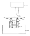
- FIG. 2 another end of the shaft member 1 is supported by a cylindrical jig 10.
- the center of the circle of the joining region 7 (corresponding to the bead 5 after welding) and the circular shape of the pulley 2 are formed.
- the center deviation (eccentricity) from the center is intentionally allowed.
- misalignment (amount of eccentricity) (for example, 0.3 mm) larger than the spot diameter (for example, 0.2 mm) is generated.
- laser welding is performed along a predetermined scanning path 8 using the laser irradiation device 11. That is, in the annular joining region 7 including the circular joining edge 3 between the end portion of the shaft member 1 and the fitting hole 2a, it intersects with the circumferential direction of the joining edge 3 a plurality of times with an interval W2.
- a laser beam 9 is irradiated along the scanning path 8 to form a belt-like bead 5, and the pulley 2 and the shaft member 1 are bonded and fixed.
- the spot diameter, laser scanning speed, and laser output during laser welding can be set according to the penetration depth.
- the spot diameter is set to 30 ⁇ m or more and 200 ⁇ m or less, and the laser scanning speed is set.
- bonding can be performed with a penetration depth of 0.7 mm.
- the spot diameter is reduced to 200 ⁇ m or less, deep penetration can be ensured locally.
- thermal influence can be suppressed, thermal distortion can be reduced, and the laser in the laser irradiation device 11 can be reduced.
- the output of the oscillator can be reduced, and the price of the laser oscillator can be suppressed.
- the welding time can be shortened compared to the welding time other than the conventional laser welding, the thermal influence can be suppressed, and the thermal strain is reduced. be able to.
- the price of the laser oscillator can be suppressed, and thermal distortion can be reduced by lowering the heat input.
- a certain dimensional difference (with backlash) is provided between the jig 10 and the shaft member 1 in order to facilitate the attachment of the shaft member 1 to the jig 10. May be set.
- laser welding is performed in a state where the shaft member 1, that is, the pulley 2 is loose with respect to the jig 10 (for example, tilted from the vertical direction).
- the joint region 7 is eccentric from the center of the pulley 2 by a backlash.
- the width W1 of the bead 5 is larger than the amount of eccentricity (the amount of backlash)
- the welding is started after the joining edge 3 is aligned with the center of the annular joining region 7, the pulley 2 and the shaft member The joining edge 3 between 1 and 1 is surely contained in the bead 5 having the width W1, so that stable joining can be performed.
- Eccentricity (Repetition accuracy of laser irradiation position) + (Concentricity between inner diameter of joint edge 3 and outer diameter of shaft member 1) + (Accuracy of attaching jig 10 to laser irradiation equipment 19) + (Jig 10 And one-side clearance between shaft member 1)
- the repetition accuracy of the laser irradiation position means the maximum distance (radiation direction) ( ⁇ m) at which the spot position shifts due to the shift of the optical system that occurs every time the product is processed.
- the coaxiality between the inner diameter of the joint edge 3 and the outer diameter of the shaft member 1 means the distance ( ⁇ m) between the center of the pulley 2 and the center of the shaft member 1 for each product.
- the one-side clearance between the jig 10 and the shaft member 1 means the maximum distance (radial direction) ( ⁇ m) of the gap generated between the jig 10 and the shaft member 1.
- the depth of penetration into the inner and outer circumferences should be different depending on the difference between the adjacent distance on the central side of the shaft member 1 and the adjacent distance on the outer peripheral side with respect to the joint edge 3.
- the spot diameter for example, 50 ⁇ m
- the laser scanning is performed at a narrow interval when crossing the joint edge 3, it is possible to prevent a substantial difference in the penetration depth from the inner and outer circumferences.
- the spot overlap width is a positive value when adjacent spots 9a overlap each other, and is a negative value when the spots overlap each other.
- the spot diameter is, for example, 50 ⁇ m.
- the variation in the penetration depth in the circumferential direction of the joining edge 3 is 10%, but the entire circumference machining time is about 30 sec.
- the wrap ratio is preferably in the range of ⁇ 40% or more and less than 30%. Within this range, the variation is within 42% to 10%, not only forming beads without gaps, but also improving the yield rate (preventing joint failure) and shortening the processing time compared with plasma arc welding. it can.
- the welding by the laser beam 9 can be made shorter than about 30 seconds.
- the reason that the time can be shortened compared with the plasma arc welding is that the energy density (J / m 2 ) is adjusted to be extremely high by condensing in laser welding even if the power of the apparatus is the same.
- the energy density (J / m 2 ) is a fixed value and cannot be adjusted high.
- the penetration depth 13 of the two members 12a and 12b is (2) in FIG. 4B. It is the same as shown in (4). 4B, (2) shows that when the laser beam 9 is irradiated at the inner end of the scanning path 8 on the first member 12a side and when the crossing interval of the scanning path 8 with respect to the bonding edge 3 is wide, the bonding edge 3 is shown.
- the penetration depth 13 on the first member 12a side close to the irradiation position is larger than that of the second member 12b.
- the penetration depth 13 of the member 12c is larger than that of the low heat transfer member 12d. Assuming that the penetration depth 13 of the high heat transfer member 12c reaches a predetermined penetration depth, the penetration depth 13 of the low heat transfer member 12d does not reach the predetermined penetration depth. In order to avoid such a case, it is necessary to set the laser output larger in accordance with the low heat transfer member 12d where the penetration depth becomes shallow, and to ensure a predetermined penetration depth on the low heat transfer member 12d side. Alternatively, instead of changing the laser output setting as described above, the laser output setting is not changed, and laser welding is performed in a state in which the laser output is set in accordance with the high heat transfer member 12c having a deep penetration depth.
- the scanning time is lengthened or the scanning path 8 is lengthened to ensure a desired penetration depth. Also good.
- lengthening the scanning path 8 it is conceivable that the scanning paths 8 are overlapped or the path is lengthened by adding one spiral or circle.
- the start point and end point of the scanning path 8 do not always have to coincide with each other, and at least the path near the start point and the path near the end point should intersect. For example, it is only necessary to overlap even 5 mm. In this way, the scanning path 8 can be set freely.
- the laser beam is not irradiated along the edge between the shaft member 101 and the fitting hole 103 of the disk member 102 but intersects with the joint edge 3. Therefore, it is possible to prevent poor welding due to misalignment of the circular joint.
- the laser beam 9 is locally irradiated to the vicinity of the joint edge 3, the amount of heat input is less than when a conventional welding method such as plasma welding or TIG welding is employed, and the thermal distortion is greatly increased. Dimensional error before and after the welding process can be greatly suppressed.
- the processing time can be shortened and the variation in the penetration depth can be reduced.
- the welding time in the conventional plasma welding was 40 seconds, but in the above-described embodiment, the welding time is 10 seconds, which can be shortened to 1 ⁇ 4, and the conventional plasma welding requires a power of 600 kw.
- the laser output can be lowered to 450 W or less, and the power can be greatly reduced.
- this invention is not limited to the said embodiment, It can implement in another various aspect as follows.
- the shape of the scanning path 8 of various laser beams 9 such as zigzag is clearly described and illustrated, but actually, it is the same as the previous embodiment.
- the shape of the scanning path 8 is clearly distinguished and described.
- the circular joint edge 3 when the circular joint edge 3 is welded from 0 ° to 360 °, it is divided into six parts, and then the part 18a of 0 ° to 60 ° is first welded and then the part of 120 ° to 180 ° 18b, 240 ° to 300 ° portion 18c, 60 ° to 120 ° portion 18d, 180 ° to 240 ° portion 18e, 300 ° to 360 ° portion 18f, and so on. Also good.
- the circular joining edge 3 is partially formed by a portion 18g of 0 ° to 5 °, a portion 18h of 120 ° to 125 °, and a portion 18i of 240 ° to 245 °. You may make it weld in three places partially weaving.
- FIG. 5B the circular joining edge 3 is partially formed by a portion 18g of 0 ° to 5 °, a portion 18h of 120 ° to 125 °, and a portion 18i of 240 ° to 245 °. You may make it weld in three places partially weaving.
- FIG. 5B the circular joining edge 3 is partially formed by a portion 18g of 0 ° to 5 °, a portion 18h of 120 ° to 125 °, and a portion 18i of 240 ° to 245 °. You may make it weld in three places partially weaving.
- FIG. 5B the circular joining edge 3 is partially formed by a portion 18g of 0 ° to 5 °, a portion 18h
- the scanning path 8 intersects the joint edge 3 at least about 8 times (for example, when the wrap ratio is ⁇ 40%) in each of the 5 ° angle ranges. As an example, when the wrap rate is ⁇ 17%, the intersection can be made about 10 times.
- the scanning path 8 is formed along the joint edge 3, but the joint area 7 is rectangular along the tangential direction of the joint edge 3, for example, as shown in FIG.
- An example is also possible in which the scanning path 8-10 overlaps a part of the joint edge 3 by setting ⁇ 10 and the zigzag scanning path 8-10 extending linearly therein.
- welding is performed not on the entire circumference of the joint edge 3 but only on a part thereof, so that variations in the penetration depth can be reduced and thermal distortion can be significantly suppressed. .
- the scanning path 8-2 intersects the circular joint edge 3 and is curved and finely meandered to continuously form a U-shape. In this way, continuous laser welding can be performed. In this way, in the previous embodiment, since the scanning speed falls at the zigzag folding angle, there is a possibility that the heat input at that portion will increase, but in this second modification, the penetration depth This variation can be made smaller than in the previous embodiment.
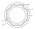
- the scanning path 8-3 intersects with the circular joint edge 3 and is curved so as to meander in a large S-shape so that the S-shaped weaving is performed. Can also be carried out continuously. In this way, the scanning path 8-3 becomes shorter as a whole than in the previous embodiment, and the processing time can be shortened.
- the scanning path 8-4 is intermittently interrupted by intermittently performing oblique weaving intersecting the circular joint edge 3 at predetermined intervals. You may make it process automatically. In this way, the scanning path 8-4 becomes shorter as a whole than in the previous embodiment, and the processing time can be shortened.
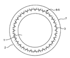
- the scanning path 8-5 is intermittently interrupted so that V-shaped weaving intersecting the circular joint edge 3 is intermittently performed at a predetermined interval. Can also be processed. In this way, the processing time can be shortened as a whole as compared with the previous embodiment.
- the scanning path 8-6 is subjected to continuous spiral weaving so as to intersect the circular joint edge 3, and the adjacent vortices are partially separated. It is also possible to perform laser welding continuously so as to overlap each other. In this way, the scanning path 8-6 is finely arranged on the joint edge 3 as a whole as compared with the previous embodiment, and as a whole, the variation in the penetration depth is reduced as compared with the previous embodiment. In addition, the processing time can be shortened. In this sixth modification, the scanning path 8-6 is finely arranged on the joint edge 3 and the spot passes through the positions of the joint edge 3 several times in a single time. Therefore, it is possible to use the laser irradiation device 11 whose power and the like are lower than those of the previous embodiment.
- the scanning path 8-7 is implemented by intermittently partially overlapping a large number of circular weavings so as to intersect the circular joint edge 3. Laser welding can also be performed intermittently. In this way, the scanning path 8-7 is arranged more finely on the joint edge 3 as a whole than in the previous embodiment, and as a whole, the variation in the penetration depth is less than that in the previous embodiment. Can do. In the seventh modified example, the scanning path 8-7 is finely arranged on the joint edge 3, and the spot passes through each position of the joint edge 3 several times in a single time. Therefore, it is possible to use the laser irradiation device 11 whose power and the like are lower than those of the previous embodiment.
- the scanning path 8-2 shown in FIG. 6 may be used as the second scanning path 8-9 so that the joint edge 3 makes a further round, and the scanning path 8-2 may be formed twice. .
- the scanning paths 8-8 and 8-9 of two rounds are finely arranged on the joint edge 3 and the spots pass through each position of the joint edge 3 several times in a single time, one scan
- the power and the like per turn can be suppressed, and it becomes possible to use the laser irradiation apparatus 11 having a low level of power and the like as compared with the second modified example of FIG. Further, the variation in the penetration depth can be made smaller than that in the second modification example of FIG.
- the pulley joining method and joining structure according to the above aspect of the present invention can prevent poor welding due to misalignment at a circular joining location, and is useful as an application to, for example, motorcycle parts.
Landscapes
- Engineering & Computer Science (AREA)
- Physics & Mathematics (AREA)
- Optics & Photonics (AREA)
- Mechanical Engineering (AREA)
- Plasma & Fusion (AREA)
- General Engineering & Computer Science (AREA)
- Laser Beam Processing (AREA)
- Pulleys (AREA)
- Transmissions By Endless Flexible Members (AREA)
Abstract
プーリーの接合方法及び接合構造は、プーリー(2)の嵌合穴(2a)に軸部材(1)を嵌合し、その後、軸部材と嵌合穴との円形の接合縁(3)に対して間隔をあけて複数回交差する走査経路(8)に沿ってレーザー光(9)を照射して、円形の接合縁と重なる帯状のビード(5)を形成し、プーリーと軸部材とを接合固定する。
Description
本発明は、固定側プーリー又は可動側プーリーと軸部材とをレーザー溶接により接合するプーリーの接合方法及び接合構造に関する。
従来、プラズマ溶接では、溶け込み深さを確保するためには加工時間が長くなり、その結果、広範囲に入熱が加わるため、熱歪により、組付け後の寸法精度が悪くなるという課題があった。
これを解消するため、最近、局所的に溶接できるレーザー溶接の適用が検討されている。
しかしながら、レーザー溶接を適用して円形の接合箇所に溶接を行う場合に、以下のような課題がある。すなわち、例えば、図13に示すように、軸部材101を円板部材102の嵌合穴103に嵌合したのち、溶接のため、治具(図示せず)で軸部材101を支持するとき、治具と軸部材101とのガタ付き(例えば鉛直方向から傾いた状態)で、嵌合穴103の縁に沿ってレーザー光を照射してレーザー溶接が行われることになり、最終製品において円環状の溶接部分104がプーリーの中心から偏心してしまい、芯ずれによる溶接不良となるといった課題があった。もし、このような芯ずれを防止しようとして、芯ずれが発生しないように大きなスポット径を使用しようとすると、レーザー照射装置として大きなパワーが必要となり、大きなエネルギーロスが発生し、かつ、装置も大型化するといった別の課題があった。
従って、本発明の目的は、前記問題を解決することにあって、円形の接合箇所に対して芯ずれによる溶接不良を防止することができるプーリーの接合方法及び接合構造を提供することにある。
前記目的を達成するために、本発明は以下のように構成する。
本発明の1つの態様によれば、車両のトルク伝達用のプーリーの嵌合穴に軸部材を嵌合し、
その後、前記軸部材と前記嵌合穴との円形の接合縁を含む円環状の接合領域内で、前記接合縁の周方向に対して間隔をあけて複数回交差する走査経路に沿ってレーザー光を照射して、前記円形の接合縁と重なる帯状のビードのレーザー溶接部を形成し、前記プーリーと前記軸部材とを接合固定する、プーリーの接合方法を提供する。
その後、前記軸部材と前記嵌合穴との円形の接合縁を含む円環状の接合領域内で、前記接合縁の周方向に対して間隔をあけて複数回交差する走査経路に沿ってレーザー光を照射して、前記円形の接合縁と重なる帯状のビードのレーザー溶接部を形成し、前記プーリーと前記軸部材とを接合固定する、プーリーの接合方法を提供する。
また、本発明の別の態様によれば、車両のトルク伝達用のプーリーの嵌合穴に軸部材が嵌合された状態で、前記軸部材と前記嵌合穴との円形の接合縁に対して交差するレーザー走査痕を有しかつ前記接合縁と重なるように形成された帯状のビードのレーザー溶接部で、前記プーリーと前記軸部材とが接合固定されたプーリーの接合構造を提供する。
本発明の前記態様によれば、円形の接合縁に対して交差するような走査経路に沿ってレーザー光を照射して接合縁と重なる帯状のビードのレーザー溶接部を形成することができ、円形の接合箇所に対して芯ずれによる溶接不良を防止することができる。
本発明のこれらと他の目的と特徴は、添付された図面についての好ましい実施形態に関連した次の記述から明らかになる。この図面においては、
本発明の実施形態にかかるプーリーの接合構造の平面図、
図1Aの接合構造の断面側面図、
本発明の実施形態にかかるプーリーの接合方法の説明図、
図2にかかるプーリーの接合方法の走査経路の説明図、
図2にかかるプーリーの接合方法のビードの説明図、
図3Aにかかるプーリーの接合方法の走査経路の部分拡大説明図、
レーザー走査痕の写真を示す拡大図、
プーリーの接合方法において、左はラップ率-17.2%のとき、右はラップ率6.2%のときの走査経路、ビードの平面状態の写真、及び溶け込み状態の写真を示す説明図、
プーリーの接合方法において、接合縁を境とする2つの部材の伝熱性が等しいときの説明図、
プーリーの接合方法において、接合縁を境とする2つの部材の伝熱性が異なるときの説明図、
プーリーの接合方法において、ビードの拡大断面の概略説明図、
プーリーの接合方法の説明図、
プーリーの接合方法において円形の接合縁を部分的に走査するときの1つの例の概略説明図、
プーリーの接合方法において円形の接合縁を部分的に走査するときの別の例の概略説明図、
前記実施形態の変形例にかかるプーリーの接合方法の説明図、
前記実施形態の第2変形例にかかるプーリーの接合方法の説明図、
前記実施形態の第3変形例にかかるプーリーの接合方法の説明図、
前記実施形態の第4変形例にかかるプーリーの接合方法の説明図、
前記実施形態の第5変形例にかかるプーリーの接合方法の説明図、
前記実施形態の第6変形例にかかるプーリーの接合方法の説明図、
前記実施形態の第7変形例にかかるプーリーの接合方法の説明図、
前記実施形態の第8変形例にかかるプーリーの接合方法の説明図、
従来のレーザー溶接を適用して円形の接合箇所に溶接を行う場合の説明図。
以下、図面を参照して本発明における実施形態を詳細に説明する。
(実施形態)
本発明の実施形態にかかるプーリーの接合方法及び接合構造は、図1A~図2に示すように、車両のトルク伝達用のプーリー、例えばベルト式CVT用の自動車用又は二輪用のような小型のプーリーのような固定側又は可動側プーリー2の筒状部2bの嵌合穴2aに軸部材1の端部を圧入して、嵌合穴2aの周囲端面と軸部材1の端部の端面とが面一状態となるように嵌合したのち、軸部材1の端部の外周縁と嵌合穴2aの内周縁との円形の接合縁3に対して、レーザー溶接を行うものである。
本発明の実施形態にかかるプーリーの接合方法及び接合構造は、図1A~図2に示すように、車両のトルク伝達用のプーリー、例えばベルト式CVT用の自動車用又は二輪用のような小型のプーリーのような固定側又は可動側プーリー2の筒状部2bの嵌合穴2aに軸部材1の端部を圧入して、嵌合穴2aの周囲端面と軸部材1の端部の端面とが面一状態となるように嵌合したのち、軸部材1の端部の外周縁と嵌合穴2aの内周縁との円形の接合縁3に対して、レーザー溶接を行うものである。
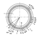
図3A及び図3Bに示すように、レーザー溶接は、円形の接合縁3の周方向の全周又はその一部に対して、接合縁3と重なる、例えば所定幅の円環状の接合領域7内で間隔をあけて接合縁3と複数回交差するジグザグ形状の走査経路8に沿ってレーザー光9を走査しつつ照射して、レーザー走査痕を有する帯状のビード5をレーザー溶接部として形成する。円環状の接合領域7としては、例えば、一定幅の円環状の領域であってもよいし、部分的に幅が異なる領域であってもよい。レーザー走査痕は、ビード5の表面で実質的に径方向に延びる線状の痕跡である。
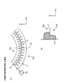
具体的には、前記実施形態では、図3Aに示すように、接合縁3を含むビード形成領域として、円環状の接合領域7を設定する。円環状の接合領域7の一例としては、径方向の幅寸法を1.5mmで一定とし、径方向の幅寸法の中央付近に接合縁3が位置するように設定する。この円環状の接合領域7の幅寸法は一例であり、接合対象物の大きさ、材質、又は、要求される接合強度などにより、適宜、設定することが可能であるが、自動車用又は二輪用のような小型のプーリー2と軸部材1との接合では、接合縁3に、レーザー光9のスポット径を超えるような隙間は通常では生じないため、最低限、スポット径よりも大きければ、接合不良を防ぐことができる。ただし、接合領域7の幅寸法が大きすぎると、加工時間の増大につながる。このため、実質的には、接合領域7の幅寸法は、スポット径の2倍~3倍が望ましい。
この円環状の接合領域7内で、接合縁3に交差するジグザグ形状の走査経路8に沿って、レーザー照射装置11でレーザー光9を連続的に走査させる。
この円環状の接合領域7内で、接合縁3に交差するジグザグ形状の走査経路8に沿って、レーザー照射装置11でレーザー光9を連続的に走査させる。
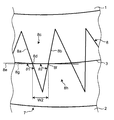
このジグザグ形状のレーザー光9の走査経路8は、図3Cに示すように、第1斜線部8aと第2斜線部8bとで構成されるV字形状8cを構成し、このV字形状8cが例えば接合縁3に沿って連続的に配置されて一筆書きで描いてV字形状のウィービングを実施し、連続溶接できるように構成されている。第1斜線部8aは、その中間部で接合縁3と交差し、その交点8dにおいて実線で示す接線8eに対して所定角度θ1で傾いて交差しつつ内側から外側に向かう経路である。第2斜線部8bは、その中間部で接合縁3と交差し、その交点8fにおいて点線で示す接線8gに対して所定角度θ2で傾いて交差しつつ外側から内側に向かう経路である。第1斜線部8aの外端と第2斜線部8bの外端とが互いに連結されてV字形状8cを構成している。一例として、接合縁3上の交点8dと交点8fとの間の間隔W2は一定としてもよいし、可変としてもよい。また、所定角度θ1及びθ2もそれぞれ一定としてもよいし、それぞれ異なる角度としてもよい。隣接するV字形状8c同士をつなぐとき、例えば、第2斜線部8bと、第2斜線部8bに連結される第1斜線部8aとで、逆さまの同じV字形状8hを構成しているが、同じV字形状に限られず、異なる形状のV字形状としてもよい。
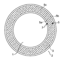
なお、このジグザグ形状の走査経路8に沿ってレーザー光9が照射された部分は、ジグザグ形状の形成開始時点から、接合熱により部分的に溶融してジグザグ形状の区別は明確には残らず互いに溶け合い、図3Bに斜線で示すとともに図3Dに写真で示すように、全体として1つの太い幅の円環状の帯状のビード5となる。図3Dに明白に示されるように、ジグザグ形状の走査経路8に沿ってレーザー光9が照射されると、ジグザグ形状の軌跡に沿って、レーザー走査痕が、ビード5の表面で実質的に径方向に延びる線状の痕跡として残っている。
この帯状のビード5は、プーリー2の筒状部2bの嵌合穴2aと軸部材1の端部とで形成された円形の接合縁3に重なり、かつ、軸部材1の端部から溶け込み深さ方向において部分的に形成されている。より具体的な一例としては、ビード5は、図3B及び図4Aに示すように、内側の細い接合内縁部5aと、外側の細い接合外縁部5bと、中間の幅広の円環状の接合本体部5cとで概略構成されている。細い接合内縁部5aと細い接合外縁部5bとは、それぞれ、接合本体部5cへの入熱により熱変成した領域である。円環状の接合本体部5cは、2つの細い接合内縁部5aと細い接合外縁部5b間に挟まれて形成され、円形の接合縁3を一定幅で重なり、かつ所望の溶け込み深さまでの部分的な溶け込み6(図4A参照)が形成されて溶接されている。一例として、筒状部2bの軸方向長さが5mmであって、ビード5が、軸部材1の端部から溶け込み深さ方向において部分的に形成されるとき、その部分的な溶け込み6の深さは1mmであり、筒状部2bの軸方向長さの50%未満が部分的な溶け込み6の深さとなっている。また、細い接合内縁部5aと細い接合外縁部5bは、それぞれ、円環状の接合本体部5cほど深くは、溶け込みが形成されていない。ここで、レーザー溶接部では、プーリー2の筒状部2bの嵌合穴2aの嵌合面(接合本体部5c)において、溶接深さ方向の一部だけ溶接させる構成となっている。これに対して、レーザーをウィービングさせて2つの部材それぞれを溶接深さ方向の全長にわたって溶かすとともに、裏当てにより部材が溶け落ちることを防ぐ、完全溶け込み溶接に関する技術があるが、そのような完全溶け込み溶接では、2つの部材の接合縁の両側近傍にエネルギーを与える必要があった。しかしながら、本発明の接合方法では、そのように接合縁の両側近傍にエネルギーを与える必要はない。
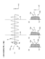
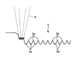
また、図4Dは、図4Aのラップ率6.2%の場合のビード5の拡大断面の概略説明図である。レーザー走査痕の巨視的な説明として、ビード5のレーザー溶接部の表面は、接合縁3に交差する方向に延びる溝部5d及び隆起部5eが接合縁3に重なって交互に並んで形成されて、プーリー2と軸部材1とが接合固定されている。また、レーザー溶接部は、溝部5d及び隆起部5eに対するプーリー2の内周側の隣接部分(内側の細い接合内縁部5a)とプーリー2の外周側の隣接部分(外側の細い接合外縁部5b)とのそれぞれに熱変成部分を有している。
このように、接合縁3と交差するようにレーザー光9を連続的にジグザグ形状に走査させることにより、接合縁3と重なる例えば所定幅の円環状の接合領域7内に、レーザー走査痕を有する帯状のビード5をレーザー溶接部として形成することにより、プーリー2と軸部材1とを安定して接合固定することができる。
この結果、円形の接合箇所としての接合縁3に対して、芯ずれによる溶接不良を防止することができる。すなわち、円形の接合縁3に沿うようにレーザー光9を走査するのではなく、レーザー光9の走査方向を接合縁3と交差させることにより、芯ずれの発生を防止することができる。さらに、円形の接合縁3を含む例えば所定幅の円環状の接合領域7を設定し、その接合領域7内に接合縁3と重なる帯状のビード5をレーザー溶接部として形成するため、接合領域7内では、多少、帯状のビード5の位置がずれても許容され、全体としては、接合領域7内に帯状のビード5が形成される限り、芯ずれの発生を防止することができる。
走査経路8の一例としては、図3Aに示すように、円形の接合縁3を中心として内外に均等の距離だけ走査しつつジグザグに形成されており、円形の接合縁3を交差する間隔W2は、一例として均等にしている。このようにすれば、部分的に形成される溶け込み深さのバラツキを小さくすることができる。なお、この交差間隔W2は等間隔に限られず、間隔の距離が異なってもよい。そのような場合には、加工時間を短縮することができる。その理由は、交差間隔W2の密の部分と疎の部分とが交互に並ぶ構成により、密の部分で接合強度を確保しながら、疎の部分で加工時間を短縮することができるためである。
次に、プーリーの接合方法について説明する。
まず、プーリー2の嵌合穴2aに軸部材1の端部を嵌合する。一例としては、嵌合穴2aに軸部材1の端部がほぼ隙間なく嵌合して、円形の線状の接合縁3が形成される。
次いで、図2に示すように、軸部材1の別の端部側を筒状の治具10で支持する。このとき、溶接前の軸部材1を治具10にセットする作業を効率良く短時間で行うため、接合領域7(溶接後はビード5に対応。)の円の中心とプーリー2の円形状の中心との芯ずれ(偏心)を、意図的に許容している。一例としては、スポット径(例えば0.2mm)よりも大きい芯ずれ(偏心量)(例えば0.3mm)を生じさせている。
次いで、レーザー照射装置11を使用して、予め決められた走査経路8に沿ってレーザー溶接を行う。すなわち、軸部材1の端部と嵌合穴2aとの円形の接合縁3を含む円環状の接合領域7内で、接合縁3の周方向に対して間隔W2をあけて複数回交差するような走査経路8に沿ってレーザー光9を照射して、帯状のビード5を形成し、プーリー2と軸部材1とを接合固定する。
ここで、レーザー溶接時のスポット径、レーザー走査速度、及びレーザー出力については、溶け込み深さに応じて設定することができる。例えば、プーリー2と軸部材1の例では、少なくとも0.1mm以上の溶け込み深さを満足することが一般に要求されるため、一例としては、スポット径を30μm以上でかつ200μm以下とし、レーザー走査速度を200mm/s以上とし、レーザー出力を450W以下とすることができる。なお、スポット径が小さいほど溶け込み深さが深くなるので、スポット径が200μm以下であれば0.1mmよりも深い溶け込み深さを確保することもできる。一例としては、0.7mmの溶け込み深さで接合することができる。
スポット径を200μm以下まで小さくすると、局所的に深い溶け込みを確保することができ、その結果、熱影響を抑えることができて、熱歪を低減することができるとともに、レーザー照射装置11内のレーザー発振器の出力を小さくすることができ、レーザー発振器の価格を抑えることができる。
また、レーザー走査速度を最低200mm/s以上まで高速化すると、従来のレーザー溶接以外の溶接時間よりも溶接時間を短縮することができるとともに、熱影響を抑えることができて、熱歪を低減することができる。
また、レーザー出力を450W以下まで下げると、レーザー発振器の価格を抑えることができるとともに、入熱を下げることにより、熱歪みを低減することができる。
なお、治具10で軸部材1を支持するとき、治具10への軸部材1の取り付けを容易にするため、治具10と軸部材1との間には一定の寸法差(ガタ付き)が設定される場合がある。このように設定すれば、治具10に対して軸部材1すなわちプーリー2がガタ付いた状態(例えば鉛直方向から傾いた状態)でレーザー溶接が行われることになり、最終製品において、円環状の接合領域7は、プーリー2の中心からガタ付き分だけ偏心することになる。ここで、この偏心量(ガタ付き分)よりも、ビード5の幅W1が大きければ、円環状の接合領域7の中央に接合縁3を合わせたのち溶接を開始すれば、プーリー2と軸部材1との間の接合縁3は幅W1のビード5内に確実に収まることになり、安定した接合が行える。
すなわち、軸部材1を治具10に支持した際のガタツキがXmmであるとすると、円環状の接合領域7の幅Xmm未満では、芯ずれ不良となる可能性がある。そこで、幅Xmm以上の円環状の接合領域7で溶け込み深さを満足させるようにすれば、芯ずれ不良が起きない。
ここで、偏心量(ガタ付き分)の求め方について説明する。
偏心量=(レーザー照射位置の繰り返し精度)+(接合縁3の内径と軸部材1の外径との同軸度)+(治具10のレーザー照射設備19への取り付け精度)+(治具10と軸部材1との片側クリアランス)
ここで、レーザー照射位置の繰り返し精度とは、製品加工の度に発生する光学系のずれによって、スポット位置がずれる最大距離(放射方向)(μm)を意味する。また、接合縁3の内径と軸部材1の外径との同軸度とは、製品毎のプーリー2の中心と軸部材1の中心との距離(μm)を意味する。また、治具10と軸部材1との片側クリアランスとは、治具10と軸部材1との間に発生する隙間の最大距離(放射方向)(μm)を意味する。
ここで、レーザー照射位置の繰り返し精度とは、製品加工の度に発生する光学系のずれによって、スポット位置がずれる最大距離(放射方向)(μm)を意味する。また、接合縁3の内径と軸部材1の外径との同軸度とは、製品毎のプーリー2の中心と軸部材1の中心との距離(μm)を意味する。また、治具10と軸部材1との片側クリアランスとは、治具10と軸部材1との間に発生する隙間の最大距離(放射方向)(μm)を意味する。
この計算式により、偏心量を求めて、この偏心量以上の幅の円環状の接合領域7で溶け込み深さを満足させるようにすれば、前記した不具合の発生を防止することができる。
なお、原理的には、接合縁3よりも軸部材1の中心側での隣接距離と外周側での隣接距離との差によって、内外周に溶け込み深さの相違が生じるはずである。が、スポット径(例えば50μm)がラップするほど、接合縁3を交差するとき狭間隔でレーザー走査すれば、内外周に実質的な溶け込み深さの相違は生じないようにすることができる。
すなわち、実際の帯状のビード5では、一例として、接合縁3の全周で隙間なく溶け込みを生じさせるため、接合縁3に対する内外での蛇行の行き帰りで、レーザースポット9a同士が重なり合うような狭い間隔でレーザー走査すればよい。ただし、レーザースポット9a同士が少し離れていても、スポット9aの周囲に溶け込みが生じるため、接合縁3の全周で隙間なく溶け込みを生じさせることができる。
ここで、レーザー光9のスポット径の重なり率、すなわち、ラップ率=接合縁3上でのスポット重なり幅/スポット径、と定義する。スポット重なり幅は、隣接するスポット9a同士が重なっているときは正の値とし、重なっていないときは負の値とする。スポット径は例えば50μmとする。
ラップ率が-63%と互いに離れた状態では、接合縁3の周方向の全周で隙間なく溶け込みが発生し、全周加工時間は約3secであった。これは、以下に列挙する例の中では、最も悪い例であり、これよりもマイナスが大きい場合には、溶け込みが無い箇所が繰り返し発生してしまう可能性があるため、好ましくない。
ラップ率が-40%と互いに離れた状態では、接合縁3の周方向の溶け込み深さのバラツキは42%であるが、十分な強度を得ることができ、全周加工時間は約7secであった。
ラップ率が-17%と互いに離れた状態では、接合縁3の周方向の溶け込み深さのバラツキは36%であるが、全周加工時間は約10secであった。
ラップ率が6%と互いに少し重なり合った状態では、接合縁3の周方向の溶け込み深さのバラツキは30%であるが、全周加工時間は約15secであった。
ラップ率が22%と互いに重なり合った状態では、接合縁3の周方向の溶け込み深さのバラツキは30%であり、全周加工時間は約20secであった。
ラップ率が30%と互いに重なり合った状態では、接合縁3の周方向の溶け込み深さのバラツキは10%であるが、全周加工時間は約30secであった。
これらの例より、ラップ率は-40%以上で30%未満の範囲が好ましい範囲である。この範囲内ならば、バラツキは42%~10%内に収まり、隙間なくビード形成するだけでなく、良品率を高め(接合不良を防ぎ)つつ、プラズマアーク溶接よりも加工時間を短縮することができる。
なお、従来のプラズマアーク溶接による全周加工時間は約30secを越える時間が必要となっているが、レーザー光9による溶接は、この約30secより短くすることができる。ここで、プラズマアーク溶接よりも時間を短縮することができる理由は、たとえ装置のパワーが同じであっても、レーザー溶接では、集光によりエネルギー密度(J/m2)を極めて高く調整することができる一方、プラズマアーク溶接では、エネルギー密度(J/m2)は固定値であり、高く調整することができないためである。
図4Bの(1)に示すように、接合縁3を境とする2つの部材12a,12bの伝熱性が等しいときには、2つの部材12a,12bの溶け込み深さ13は、図4Bの(2)~(4)に示すように同じである。なお、図4Bの(2)は、走査経路8の第1部材12a側の内端でレーザー光9を照射したときでかつ接合縁3に対する走査経路8の交差間隔が広いとき、接合縁3を境とする径方向断面14での2つの部材12a,12bうち照射位置に近い第1部材12a側の溶け込み深さ13が第2部材12bより大きくなることを表している。図4Bの(3)では、走査経路8の第1部材12a側の内端でレーザー光9を照射したときでかつ接合縁3に対する走査経路8の交差間隔が狭いとき、接合縁3を境とする径方向断面14での2つの部材12a,12bの溶け込み深さ13は同じになることを表している。図4Bの(4)は、走査経路8の接合縁3でレーザー光9を照射したとき、接合縁3を境とする径方向断面15での2つの部材12a,12bの溶け込み深さ13が等しいことを表している。
しかしながら。図4Cの(1)に示すように、2つの部材12c,12d間での含有炭素量の相違により伝熱性が異なり、高伝熱部材12cと低伝熱部材12dとが隣接するときには、溶け込みが2つの部材12c,12d間の境界である接合縁3で非連続になり、低伝熱部材12d側では所定の溶け込み深さに到達しない場合がある。すなわち、図4Cの(2)は、走査経路8の接合縁3でレーザー光9を照射したとき、接合縁3を境とする径方向断面16での2つの部材12c,12dのうち高伝熱部材12cの溶け込み深さ13が低伝熱部材12dよりも大きくなることを表している。高伝熱部材12cの溶け込み深さ13が所定の溶け込み深さまで到達していると仮定すると、低伝熱部材12dの溶け込み深さ13は所定の溶け込み深さまで到達していないことになる。このような場合を避けるため、溶け込み深さが浅くなる低伝熱部材12dに合わせてレーザー出力をより大きく設定し、低伝熱部材12d側で所定の溶け込み深さを確保する必要がある。又は、そのようにレーザー出力の設定を変更する代わりに、レーザー出力の設定は変更せずに、溶け込み深さが深くなる高伝熱部材12cに合わせてレーザー出力を設定した状態でレーザー溶接を行うが、そのレーザー出力では溶け込み深さが不足する低伝熱部材12dの溶接個所では、走査時間を長くするか、又は、走査経路8を長くして、所望の溶け込み深さを確保するようにしてもよい。走査経路8を長くする例としては、走査経路8を重複させるか又は1つの渦巻き又は円を追加して経路を長くすることが考えられる。
走査経路8の開始点と終点とは必ず一致させる必要はなく、最低限、開始点付近の経路と終点付近の経路とが交差すればよい。例えば5mmだけでもオーバーラップさせるようにすればよい。このようにすることで、走査経路8を自由に設定することができる。
前記実施形態によれば、従来のレーザー溶接に対する効果として、軸部材101と円板部材102の嵌合穴103との縁に沿ってレーザー光を照射するのではなく、接合縁3と交差するように走査するため、円形の接合箇所に対して芯ずれによる溶接不良を防止することができる。また、接合縁3の近傍に対してレーザー光9を局所的に照射するため、プラズマ溶接やTIG溶接などの従来の溶接法を採用する場合に比べて入熱量が少なくて済み、熱歪が大幅に減少し、溶接工程の前後での寸法誤差を大幅に抑制することができる。このため、従来、TIG溶接などでは、プーリーに生じた熱歪を取るための削り工程又は熱プレスによる微調整工程が溶接後に必要となっていたが、すべて不要となり、組み付け精度及び製品精度を向上させることができる。また、プラズマ溶接に対する効果として、入熱量が少なくて済むため、加工時間の短縮が図れ、かつ、溶け込み深さのバラツキを少なくすることができる。一例として、従来のプラズマ溶接では溶接時間が40秒であったのが、前記実施形態では10秒となり、1/4に短縮することが可能であり、従来のプラズマ溶接では600kwのパワーが必要であったのが、レーザー出力として450W以下まで下げることができ、パワーを大幅に削減することが可能である。
なお、本発明は前記実施形態に限定されるものではなく、以下のように、その他種々の態様で実施できる。ただし、この明細書及び図面では、理解しやすくするため、ジグザグなどの様々なレーザー光9の走査経路8の形状を明確に記載及び図示しているが、実際には、先の実施形態と同様に、走査経路8の形状の形成開始時点から、接合熱により部分的に溶融して走査経路8の形状の区別は明確には残らず互いに溶け合い、全体として1つの太い幅の帯状のビード5となっている。しかしながら、説明上、及び、理解しやすくするため、走査経路8の形状を明確に区別して説明する。
(第1変形例)
前記実施形態の第1変形例として、図5Aに示すように、点線で示す円形の接合縁3の全周を走査経路8としてレーザー溶接するとき、全周を複数の領域に分割して、隣接する領域ではなく、隣接しない、例えば1つおきの領域を順に溶接することにより、熱影響の拡散を抑制するようにしてもよい。一例として、円形の接合縁3を0°~360°まで溶接するとき6個の部分に分割したのち、まず、0°~60°の部分18aを溶接し、次いで、120°~180°の部分18b、240°~300°の部分18c、60°~120°の部分18d、180°~240°の部分18e、300°~360°の部分18fというように、部分的に順に溶接するようにしてもよい。
前記実施形態の第1変形例として、図5Aに示すように、点線で示す円形の接合縁3の全周を走査経路8としてレーザー溶接するとき、全周を複数の領域に分割して、隣接する領域ではなく、隣接しない、例えば1つおきの領域を順に溶接することにより、熱影響の拡散を抑制するようにしてもよい。一例として、円形の接合縁3を0°~360°まで溶接するとき6個の部分に分割したのち、まず、0°~60°の部分18aを溶接し、次いで、120°~180°の部分18b、240°~300°の部分18c、60°~120°の部分18d、180°~240°の部分18e、300°~360°の部分18fというように、部分的に順に溶接するようにしてもよい。
また、全周をレーザー溶接する代わりに、全周の一部のみを走査経路8-1として、部分的にレーザー溶接することにより、熱影響の拡散をより抑制するようにしてもよい。例えば、図5Bに示すように、円形の接合縁3を、部分的に、0°~5°の部分18gと、120°~125°の部分18hと、240°~245°の部分18iとの3か所に、部分的にウィービングして溶接するようにしてもよい。又は、図5Cに示すように、0°~5°の部分18jと、90°~95°の部分18kと、180°~185°の部分18mと、270°~275°の部分18nとの4か所に対して、部分18j、部分18m、部分18k、部分18nのように対角線に配置された部分の順番でウィービングして溶接するようにしてもよい。それぞれの5°の角度範囲内の部分で、接合縁3に対して走査経路8は、最低8回程度(例えばラップ率が-40%のときなどにおいて)交差するのが好ましい。一例としては、ラップ率が-17%のとき、約10回程度交差することができる。
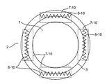
なお、前記例では、接合縁3に沿って走査経路8を形成しているが、接合縁3に沿わずに、例えば図5Dに示すように、接合縁3の接線方向に長方形の接合領域7-10を設定して、その中でジグザグの走査経路8-10が直線的に延びることにより、走査経路8-10が接合縁3の一部と重なるような例も可能である。
この第1変形例によれば、接合縁3の全周ではなく、一部のみ溶接を実施するため、溶け込み深さのバラツキを少なくすることができるとともに、熱歪を大幅に抑制することができる。
(第2変形例)
第2変形例として、図6に示すように、走査経路8-2を、円形の接合縁3に対して交差しかつ湾曲して細かく蛇行するようにして、U字形状を連続的に形成するようにウィービングして連続的にレーザー溶接することもできる。このようにすれば、先の実施形態では、ジグザグ形状の折り返しの角で走査速度が落ちるために当該部分での入熱が大きくなる可能性があるが、この第2変形例では、溶け込み深さのバラツキを先の実施形態よりも小さくすることができる。
第2変形例として、図6に示すように、走査経路8-2を、円形の接合縁3に対して交差しかつ湾曲して細かく蛇行するようにして、U字形状を連続的に形成するようにウィービングして連続的にレーザー溶接することもできる。このようにすれば、先の実施形態では、ジグザグ形状の折り返しの角で走査速度が落ちるために当該部分での入熱が大きくなる可能性があるが、この第2変形例では、溶け込み深さのバラツキを先の実施形態よりも小さくすることができる。
(第3変形例)
第3変形例として、図7に示すように、走査経路8-3を、円形の接合縁3に対して交差しかつ湾曲してS字状に大きく蛇行するようにして、S字形状のウィービングを連続的に実施することもできる。このようにすれば、全体として先の実施形態よりも走査経路8-3が短くなり、加工時間を短縮することができる。
第3変形例として、図7に示すように、走査経路8-3を、円形の接合縁3に対して交差しかつ湾曲してS字状に大きく蛇行するようにして、S字形状のウィービングを連続的に実施することもできる。このようにすれば、全体として先の実施形態よりも走査経路8-3が短くなり、加工時間を短縮することができる。
(第4変形例)
第4変形例として、図8に示すように、走査経路8-4を、円形の接合縁3に対して交差する斜線のウィービングを所定間隔で間欠的に実施するようにして、非連続で断続的に加工するようにしてもよい。このようにすれば、全体として先の実施形態よりも走査経路8-4が短くなり、加工時間を短縮することができる。
第4変形例として、図8に示すように、走査経路8-4を、円形の接合縁3に対して交差する斜線のウィービングを所定間隔で間欠的に実施するようにして、非連続で断続的に加工するようにしてもよい。このようにすれば、全体として先の実施形態よりも走査経路8-4が短くなり、加工時間を短縮することができる。
(第5変形例)
第5変形例として、図9に示すように、走査経路8-5を、円形の接合縁3に対して交差するV字のウィービングを所定間隔で間欠的に実施するように、非連続で断続的に加工することもできる。このようにすれば、全体として先の実施形態よりも加工時間を短縮することができる。
第5変形例として、図9に示すように、走査経路8-5を、円形の接合縁3に対して交差するV字のウィービングを所定間隔で間欠的に実施するように、非連続で断続的に加工することもできる。このようにすれば、全体として先の実施形態よりも加工時間を短縮することができる。
(第6変形例)
第6変形例として、図10に示すように、走査経路8-6を、円形の接合縁3に対して交差するように連続した螺旋形状のウィービングを実施し、かつ、隣接した渦同士を部分的に重ね合せるように連続的にレーザー溶接することもできる。このようにすれば、全体として先の実施形態よりも接合縁3上で走査経路8-6が細かく配置されることになり、全体として先の実施形態よりも溶け込み深さのバラツキを少なくすることができる上に加工時間を短縮することができる。この第6変形例では、接合縁3上で走査経路8-6が細かく配置されて接合縁3の各位置を単時間で複数回スポットが近接して通過するため、一回あたりのパワー等を抑制することができ、先の実施形態と比較して、パワー等が低レベルのレーザー照射装置11を使用することが可能となる。
第6変形例として、図10に示すように、走査経路8-6を、円形の接合縁3に対して交差するように連続した螺旋形状のウィービングを実施し、かつ、隣接した渦同士を部分的に重ね合せるように連続的にレーザー溶接することもできる。このようにすれば、全体として先の実施形態よりも接合縁3上で走査経路8-6が細かく配置されることになり、全体として先の実施形態よりも溶け込み深さのバラツキを少なくすることができる上に加工時間を短縮することができる。この第6変形例では、接合縁3上で走査経路8-6が細かく配置されて接合縁3の各位置を単時間で複数回スポットが近接して通過するため、一回あたりのパワー等を抑制することができ、先の実施形態と比較して、パワー等が低レベルのレーザー照射装置11を使用することが可能となる。
(第7変形例)
第7変形例として、図11に示すように、走査経路8-7を、円形の接合縁3に対して交差するように多数の円形状のウィービングを断続的に一部重なるように実施して、断続的にレーザー溶接することもできる。このようにすれば、全体として先の実施形態よりも接合縁3上で走査経路8-7が細かく配置されることになり、全体として先の実施形態よりも溶け込み深さのバラツキを少なくすることができる。この第7変形例では、接合縁3上で走査経路8-7が細かく配置されて接合縁3の各位置を単時間で複数回スポットが近接して通過するため、一回あたりのパワー等を抑制することができ、先の実施形態と比較して、パワー等が低レベルのレーザー照射装置11を使用することが可能となる。
第7変形例として、図11に示すように、走査経路8-7を、円形の接合縁3に対して交差するように多数の円形状のウィービングを断続的に一部重なるように実施して、断続的にレーザー溶接することもできる。このようにすれば、全体として先の実施形態よりも接合縁3上で走査経路8-7が細かく配置されることになり、全体として先の実施形態よりも溶け込み深さのバラツキを少なくすることができる。この第7変形例では、接合縁3上で走査経路8-7が細かく配置されて接合縁3の各位置を単時間で複数回スポットが近接して通過するため、一回あたりのパワー等を抑制することができ、先の実施形態と比較して、パワー等が低レベルのレーザー照射装置11を使用することが可能となる。
(第8変形例)
第8変形例として、図12に示すように、図6に示す走査経路8-2を1周目の走査経路8-8として接合縁3を一周したのち、接合縁3の周方向の位相をずらせ、次いで、図6に示す走査経路8-2を2周目の走査経路8-9として接合縁3をさらに一周するようにして、走査経路8-2を2周形成するようにしてもよい。このようにすれば、接合縁3上で2周の走査経路8-8,8-9が細かく配置されて接合縁3の各位置を単時間で複数回スポットが近接して通過するため、一回あたりのパワー等を抑制することができ、図6の第2変形例と比較して、パワー等が低レベルのレーザー照射装置11を使用することが可能となる。また、溶け込み深さのバラツキを図6の第2変形例よりも小さくすることができる。
第8変形例として、図12に示すように、図6に示す走査経路8-2を1周目の走査経路8-8として接合縁3を一周したのち、接合縁3の周方向の位相をずらせ、次いで、図6に示す走査経路8-2を2周目の走査経路8-9として接合縁3をさらに一周するようにして、走査経路8-2を2周形成するようにしてもよい。このようにすれば、接合縁3上で2周の走査経路8-8,8-9が細かく配置されて接合縁3の各位置を単時間で複数回スポットが近接して通過するため、一回あたりのパワー等を抑制することができ、図6の第2変形例と比較して、パワー等が低レベルのレーザー照射装置11を使用することが可能となる。また、溶け込み深さのバラツキを図6の第2変形例よりも小さくすることができる。
なお、前記様々な実施形態又は変形例のうちの任意の実施形態又は変形例を適宜組み合わせることにより、それぞれの有する効果を奏するようにすることができる。また、実施形態同士の組み合わせ又は実施例同士の組み合わせ又は実施形態と実施例との組み合わせが可能であると共に、異なる実施形態又は実施例の中の特徴同士の組み合わせも可能である。
本発明の前記態様にかかるプーリーの接合方法及び接合構造は、円形の接合箇所に対して芯ずれによる溶接不良を防止することができ、例えば2輪車用部品等への適用として有用である。
1 軸部材
2 プーリー
2a 嵌合穴
2b 筒状部
3 接合縁
5 ビード
5a 内側の細い接合内縁部
5b 外側の細い接合外縁部
5c 幅広の円環状の接合本体部
5d 溝部
5e 隆起部
6 溶け込み
7 円環状の接合領域
7-10 長方形の接合領域
8,8-1~8-10 走査経路
8a 第1斜線部
8b 第2斜線部
8c V字形状
8d,8f 交点
8e,8g 接線
8h 逆V字形状
9 レーザー光
9a スポット
10 治具
11 レーザー照射装置
12a 第1部材
12b 第2部材
12c 高伝熱部材
12d 低伝熱部材
13 溶け込み深さ
14,15,16 径方向断面
18a~18k,18m,18n 分割された接合縁の部分
19 レーザー照射設備
2 プーリー
2a 嵌合穴
2b 筒状部
3 接合縁
5 ビード
5a 内側の細い接合内縁部
5b 外側の細い接合外縁部
5c 幅広の円環状の接合本体部
5d 溝部
5e 隆起部
6 溶け込み
7 円環状の接合領域
7-10 長方形の接合領域
8,8-1~8-10 走査経路
8a 第1斜線部
8b 第2斜線部
8c V字形状
8d,8f 交点
8e,8g 接線
8h 逆V字形状
9 レーザー光
9a スポット
10 治具
11 レーザー照射装置
12a 第1部材
12b 第2部材
12c 高伝熱部材
12d 低伝熱部材
13 溶け込み深さ
14,15,16 径方向断面
18a~18k,18m,18n 分割された接合縁の部分
19 レーザー照射設備
Claims (22)
- 車両のトルク伝達用のプーリーの嵌合穴に軸部材を嵌合し、
その後、前記軸部材と前記嵌合穴との円形の接合縁を含む円環状の接合領域内で、前記接合縁の周方向に対して間隔をあけて複数回交差する走査経路に沿ってレーザー光を照射して、前記円形の接合縁と重なる帯状のビードを形成し、前記プーリーと前記軸部材とを接合固定する、プーリーの接合方法。 - 前記嵌合穴に前記軸部材が嵌合するとき、前記プーリーの筒状部の前記嵌合穴に前記軸部材の端部が、前記嵌合穴の周囲端面と前記軸部材の前記端部の端面とが面一状態となるように嵌合し、
前記ビードを形成するとき、前記ビードが、前記筒状部の前記嵌合穴と前記軸部材の前記端部とで形成された前記円形の接合縁に重なり、かつ、前記軸部材の前記端部から溶け込み深さ方向において部分的に形成されている、
請求項1に記載のプーリーの接合方法。 - 前記帯状のビードは、前記円形の接合縁と交差する斜線部が互いに連結されたジグザグ形状である、
請求項1又は2に記載のプーリーの接合方法。 - 前記走査経路は、前記円形の接合縁と交差する螺旋形状である、
請求項1又は2に記載のプーリーの接合方法。 - 前記走査経路は、前記円形の接合縁と交差する湾曲した蛇行形状である、
請求項1又は2に記載のプーリーの接合方法。 - 前記レーザー光を照射するとき、前記軸部材は治具により支持された状態で前記レーザー光が照射され、前記治具に対する前記円環状の接合領域が前記プーリーの中心から偏心した偏心量よりも、前記帯状のビードの径方向の寸法が大きい、
請求項1~5のいずれか1つに記載のプーリーの接合方法。 - 前記レーザー光を照射するとき、前記偏心量よりも、前記レーザー光のスポット径のほうが小さい状態で前記レーザー光を照射する、
請求項6に記載のプーリーの接合方法。 - 前記走査経路は、前記円形の接合縁の全周において交差する、
請求項1~7のいずれか1つに記載のプーリーの接合方法。 - 前記走査経路は、前記円形の接合縁の一部において交差する、
請求項1~7のいずれか1つに記載のプーリーの接合方法。 - 前記走査経路は、前記接合縁に対して蛇行することにより前記接合縁の周方向に対して間隔をあけて複数回交差するとき、前記接合縁上で前記レーザー光のレーザースポット同士が重なり合うスポット径の重なり率をラップ率とし、ラップ率=前記接合縁上でのスポット重なり幅/スポット径、と定義するとき、
前記ラップ率が-40%以上で30%未満とする、
請求項1~9のいずれか1つに記載のプーリーの接合方法。 - 前記プーリーと前記軸部材とは、いずれか一方が高伝熱部材であり、他方が低伝熱部材であって、前記高伝熱部材での走査経路の長さよりも前記低伝熱部材での走査経路の長さを長くする、
請求項1~10のいずれか1つに記載のプーリーの接合方法。 - 車両のトルク伝達用のプーリーの嵌合穴に軸部材が嵌合された状態で、前記軸部材と前記嵌合穴との円形の接合縁に対して交差するレーザー走査痕を有しかつ前記接合縁と重なるように形成された帯状のビードのレーザー溶接部で、前記プーリーと前記軸部材とが接合固定されたプーリーの接合構造。
- 前記プーリーは前記嵌合穴を有する筒状部を有し、前記軸部材は前記嵌合穴に嵌合される端部を有し、前記筒状部の前記嵌合穴に前記軸部材の前記端部が、前記嵌合穴の周囲端面と前記軸部材の前記端部の端面とが面一状態となるように嵌合した状態で、前記筒状部の前記嵌合穴と前記軸部材の前記端部とで前記円形の接合縁を形成し、前記軸部材の前記端部から、前記ビードが、前記軸部材の前記端部から溶け込み深さ方向において部分的に形成されている、
請求項12に記載のプーリーの接合構造。 - 前記帯状のビードは、前記円形の接合縁と交差する斜線部が互いに連結されたジグザグ形状でかつ前記接合縁と重なるように形成されている、
請求項12又は13に記載のプーリーの接合構造。 - 前記帯状のビードは、前記円形の接合縁と交差する螺旋形状でかつ前記接合縁と重なるように形成されている、
請求項12又は13に記載のプーリーの接合構造。 - 前記帯状のビードは、前記円形の接合縁と交差する湾曲した蛇行形状でかつ前記接合縁と重なるように形成されている、
請求項12又は13に記載のプーリーの接合構造。 - 前記帯状のビードは、前記円形の接合縁の全周において交差しかつ前記接合縁と重なるように形成されている、
請求項12~16のいずれか1つに記載のプーリーの接合構造。 - 前記帯状のビードは、前記円形の接合縁の一部において交差しかつ前記接合縁と重なるように形成されている、
請求項12~16のいずれか1つに記載のプーリーの接合構造。 - 前記レーザー走査痕は、前記接合縁に交差する方向に延びる溝部及び隆起部が前記接合縁に重なって交互に並んで形成されたものである、
請求項12~18のいずれか1つに記載のプーリーの接合構造。 - 前記レーザー溶接部は、前記溝部及び前記隆起部に対する前記プーリーの内周側の隣接部分と前記プーリーの外周側の隣接部分とのそれぞれに熱変成部分を有する、
請求項19に記載のプーリーの接合構造。 - 前記レーザー溶接部が大略前記円形の接合縁沿いでかつ所定の中心周りに形成されていて、この中心は前記プーリーの形状中心から偏心していて、この偏心量よりも前記帯状のビードの幅方向の寸法が大きい、
請求項12~20のいずれか1つに記載のプーリーの接合構造。 - 前記レーザー溶接部における溶け込み深さの周方向のバラツキは42%~10%である、
請求項12~21のいずれか1つに記載のプーリーの接合構造。
Applications Claiming Priority (2)
| Application Number | Priority Date | Filing Date | Title |
|---|---|---|---|
| JP2016230409A JP6802695B2 (ja) | 2016-11-28 | 2016-11-28 | プーリーの接合方法及び接合構造 |
| JP2016-230409 | 2016-11-28 |
Publications (1)
| Publication Number | Publication Date |
|---|---|
| WO2018096786A1 true WO2018096786A1 (ja) | 2018-05-31 |
Family
ID=62194866
Family Applications (1)
| Application Number | Title | Priority Date | Filing Date |
|---|---|---|---|
| PCT/JP2017/035285 Ceased WO2018096786A1 (ja) | 2016-11-28 | 2017-09-28 | プーリーの接合方法及び接合構造 |
Country Status (2)
| Country | Link |
|---|---|
| JP (1) | JP6802695B2 (ja) |
| WO (1) | WO2018096786A1 (ja) |
Cited By (3)
| Publication number | Priority date | Publication date | Assignee | Title |
|---|---|---|---|---|
| JP2019042803A (ja) * | 2017-08-31 | 2019-03-22 | 株式会社神戸製鋼所 | 接合体、接合体の製造方法、及び接合体の製造装置 |
| JP2020040103A (ja) * | 2018-09-12 | 2020-03-19 | トヨタ自動車株式会社 | コイル線のレーザ溶接方法 |
| CN119525706A (zh) * | 2023-08-21 | 2025-02-28 | 广州汽车集团股份有限公司 | 激光焊接方法及装置 |
Families Citing this family (1)
| Publication number | Priority date | Publication date | Assignee | Title |
|---|---|---|---|---|
| WO2025188079A1 (ko) * | 2024-03-08 | 2025-09-12 | 주식회사 엘지에너지솔루션 | 용접방법, 용접품 및 전지모듈 |
Citations (4)
| Publication number | Priority date | Publication date | Assignee | Title |
|---|---|---|---|---|
| JPH02137688A (ja) * | 1988-11-18 | 1990-05-25 | Fuji Electric Co Ltd | レーザ加工装置 |
| JPH10103438A (ja) * | 1996-08-07 | 1998-04-21 | Honda Motor Co Ltd | Vベルト用プーリ半体 |
| JP2000197982A (ja) * | 1998-12-28 | 2000-07-18 | Nippei Toyama Corp | レ―ザ溶接方法及び溶接装置 |
| JP2014213374A (ja) * | 2013-04-30 | 2014-11-17 | 株式会社Gsユアサ | 接合体製造方法、蓄電素子製造方法、溶接制御プログラム |
Family Cites Families (2)
| Publication number | Priority date | Publication date | Assignee | Title |
|---|---|---|---|---|
| JPH09206969A (ja) * | 1996-01-31 | 1997-08-12 | Mazda Motor Corp | レーザヘリ溶接部材およびその溶接方法 |
| JP2011230158A (ja) * | 2010-04-28 | 2011-11-17 | Suzuki Motor Corp | 亜鉛めっき鋼板のレーザ重ね溶接方法 |
-
2016
- 2016-11-28 JP JP2016230409A patent/JP6802695B2/ja active Active
-
2017
- 2017-09-28 WO PCT/JP2017/035285 patent/WO2018096786A1/ja not_active Ceased
Patent Citations (4)
| Publication number | Priority date | Publication date | Assignee | Title |
|---|---|---|---|---|
| JPH02137688A (ja) * | 1988-11-18 | 1990-05-25 | Fuji Electric Co Ltd | レーザ加工装置 |
| JPH10103438A (ja) * | 1996-08-07 | 1998-04-21 | Honda Motor Co Ltd | Vベルト用プーリ半体 |
| JP2000197982A (ja) * | 1998-12-28 | 2000-07-18 | Nippei Toyama Corp | レ―ザ溶接方法及び溶接装置 |
| JP2014213374A (ja) * | 2013-04-30 | 2014-11-17 | 株式会社Gsユアサ | 接合体製造方法、蓄電素子製造方法、溶接制御プログラム |
Cited By (4)
| Publication number | Priority date | Publication date | Assignee | Title |
|---|---|---|---|---|
| JP2019042803A (ja) * | 2017-08-31 | 2019-03-22 | 株式会社神戸製鋼所 | 接合体、接合体の製造方法、及び接合体の製造装置 |
| JP2020040103A (ja) * | 2018-09-12 | 2020-03-19 | トヨタ自動車株式会社 | コイル線のレーザ溶接方法 |
| JP7107791B2 (ja) | 2018-09-12 | 2022-07-27 | トヨタ自動車株式会社 | コイル線のレーザ溶接方法 |
| CN119525706A (zh) * | 2023-08-21 | 2025-02-28 | 广州汽车集团股份有限公司 | 激光焊接方法及装置 |
Also Published As
| Publication number | Publication date |
|---|---|
| JP6802695B2 (ja) | 2020-12-16 |
| JP2018087590A (ja) | 2018-06-07 |
Similar Documents
| Publication | Publication Date | Title |
|---|---|---|
| WO2018096786A1 (ja) | プーリーの接合方法及び接合構造 | |
| CN107160037B (zh) | 激光焊接装置和激光焊接方法 | |
| JP5609632B2 (ja) | レーザ重ね溶接方法 | |
| US6591499B1 (en) | Method for manufacturing outlet nozzles for rocket engines | |
| US7022940B2 (en) | Combustor linear and method for making thereof | |
| CN109070271B (zh) | 叠置的铝工件的激光点焊 | |
| US10060482B2 (en) | Joint-site design comprising a hub and a shaft or a gear being friction welded | |
| CN107735208A (zh) | 激光焊接重叠的金属工件 | |
| JP2014522730A (ja) | ワークピースの一体溶接方法 | |
| JP2015124875A (ja) | 差動装置の製造方法 | |
| JP2018087590A5 (ja) | ||
| JP2012122388A (ja) | 中空エンジンバルブの溶接方法 | |
| WO2014024033A1 (en) | Method of forming a pipe joint and pipe joint | |
| JP2017040368A (ja) | トルクコンバータのコアリングの接合方法、トルクコンバータの製造方法、及びそれを用いて製造されたトルクコンバータ | |
| JP5368814B2 (ja) | 樹脂溶着方法 | |
| CN110394549A (zh) | 激光焊接方法 | |
| CN112917011A (zh) | 一种飞机发动机排气管端头法兰的激光焊接方法 | |
| JP2019166533A (ja) | レーザー重ね溶接の構造および方法 | |
| WO2022196822A1 (ja) | 回転電機用ステータ製造方法 | |
| JP4173986B2 (ja) | ハニカム構造体の溶接方法 | |
| RU2572435C2 (ru) | Способ сварки деталей различного диаметра и разной толщины | |
| KR102700843B1 (ko) | 로터 샤프트 | |
| KR102700842B1 (ko) | 로터 샤프트 | |
| KR102700841B1 (ko) | 로터 샤프트 | |
| JP2015217396A (ja) | 金属中空部材の摩擦圧接方法および発電設備用部材 |
Legal Events
| Date | Code | Title | Description |
|---|---|---|---|
| 121 | Ep: the epo has been informed by wipo that ep was designated in this application |
Ref document number: 17873657 Country of ref document: EP Kind code of ref document: A1 |
|
| NENP | Non-entry into the national phase |
Ref country code: DE |
|
| 122 | Ep: pct application non-entry in european phase |
Ref document number: 17873657 Country of ref document: EP Kind code of ref document: A1 |