WO2018092394A1 - メモリカード及び動画再生装置 - Google Patents
メモリカード及び動画再生装置 Download PDFInfo
- Publication number
- WO2018092394A1 WO2018092394A1 PCT/JP2017/032721 JP2017032721W WO2018092394A1 WO 2018092394 A1 WO2018092394 A1 WO 2018092394A1 JP 2017032721 W JP2017032721 W JP 2017032721W WO 2018092394 A1 WO2018092394 A1 WO 2018092394A1
- Authority
- WO
- WIPO (PCT)
- Prior art keywords
- moving image
- memory card
- sensor
- unit
- electronic device
- Prior art date
- Legal status (The legal status is an assumption and is not a legal conclusion. Google has not performed a legal analysis and makes no representation as to the accuracy of the status listed.)
- Ceased
Links
Images









Classifications
-
- H—ELECTRICITY
- H04—ELECTRIC COMMUNICATION TECHNIQUE
- H04N—PICTORIAL COMMUNICATION, e.g. TELEVISION
- H04N23/00—Cameras or camera modules comprising electronic image sensors; Control thereof
- H04N23/60—Control of cameras or camera modules
- H04N23/68—Control of cameras or camera modules for stable pick-up of the scene, e.g. compensating for camera body vibrations
- H04N23/682—Vibration or motion blur correction
- H04N23/683—Vibration or motion blur correction performed by a processor, e.g. controlling the readout of an image memory
-
- H—ELECTRICITY
- H04—ELECTRIC COMMUNICATION TECHNIQUE
- H04N—PICTORIAL COMMUNICATION, e.g. TELEVISION
- H04N5/00—Details of television systems
- H04N5/76—Television signal recording
- H04N5/907—Television signal recording using static stores, e.g. storage tubes or semiconductor memories
-
- H—ELECTRICITY
- H04—ELECTRIC COMMUNICATION TECHNIQUE
- H04N—PICTORIAL COMMUNICATION, e.g. TELEVISION
- H04N23/00—Cameras or camera modules comprising electronic image sensors; Control thereof
-
- H—ELECTRICITY
- H04—ELECTRIC COMMUNICATION TECHNIQUE
- H04N—PICTORIAL COMMUNICATION, e.g. TELEVISION
- H04N23/00—Cameras or camera modules comprising electronic image sensors; Control thereof
- H04N23/60—Control of cameras or camera modules
-
- H—ELECTRICITY
- H04—ELECTRIC COMMUNICATION TECHNIQUE
- H04N—PICTORIAL COMMUNICATION, e.g. TELEVISION
- H04N23/00—Cameras or camera modules comprising electronic image sensors; Control thereof
- H04N23/60—Control of cameras or camera modules
- H04N23/68—Control of cameras or camera modules for stable pick-up of the scene, e.g. compensating for camera body vibrations
- H04N23/681—Motion detection
- H04N23/6812—Motion detection based on additional sensors, e.g. acceleration sensors
-
- H—ELECTRICITY
- H04—ELECTRIC COMMUNICATION TECHNIQUE
- H04N—PICTORIAL COMMUNICATION, e.g. TELEVISION
- H04N5/00—Details of television systems
- H04N5/76—Television signal recording
- H04N5/765—Interface circuits between an apparatus for recording and another apparatus
- H04N5/77—Interface circuits between an apparatus for recording and another apparatus between a recording apparatus and a television camera
- H04N5/772—Interface circuits between an apparatus for recording and another apparatus between a recording apparatus and a television camera the recording apparatus and the television camera being placed in the same enclosure
-
- H—ELECTRICITY
- H04—ELECTRIC COMMUNICATION TECHNIQUE
- H04N—PICTORIAL COMMUNICATION, e.g. TELEVISION
- H04N5/00—Details of television systems
- H04N5/76—Television signal recording
- H04N5/91—Television signal processing therefor
-
- H—ELECTRICITY
- H04—ELECTRIC COMMUNICATION TECHNIQUE
- H04N—PICTORIAL COMMUNICATION, e.g. TELEVISION
- H04N9/00—Details of colour television systems
- H04N9/79—Processing of colour television signals in connection with recording
- H04N9/80—Transformation of the television signal for recording, e.g. modulation, frequency changing; Inverse transformation for playback
-
- H—ELECTRICITY
- H04—ELECTRIC COMMUNICATION TECHNIQUE
- H04N—PICTORIAL COMMUNICATION, e.g. TELEVISION
- H04N9/00—Details of colour television systems
- H04N9/79—Processing of colour television signals in connection with recording
- H04N9/80—Transformation of the television signal for recording, e.g. modulation, frequency changing; Inverse transformation for playback
- H04N9/804—Transformation of the television signal for recording, e.g. modulation, frequency changing; Inverse transformation for playback involving pulse code modulation of the colour picture signal components
- H04N9/8042—Transformation of the television signal for recording, e.g. modulation, frequency changing; Inverse transformation for playback involving pulse code modulation of the colour picture signal components involving data reduction
-
- H—ELECTRICITY
- H04—ELECTRIC COMMUNICATION TECHNIQUE
- H04N—PICTORIAL COMMUNICATION, e.g. TELEVISION
- H04N9/00—Details of colour television systems
- H04N9/79—Processing of colour television signals in connection with recording
- H04N9/87—Regeneration of colour television signals
Definitions
- the present invention relates to a memory card and a moving image playback device, and more particularly to a memory card capable of recording camera shake information when recording a moving image and a moving image playback device that plays back a moving image recorded on the memory card.
- Non-Patent Document 1 A method of correcting image blurring by software processing using a personal computer has been proposed.
- Patent Document 1 describes a memory card with a built-in gyro sensor and a photographing device (mobile phone) that detects the tilt of the optical axis using the memory card.
- This photographing device detects tilt information of a photographing optical axis at the time of photographing a subject (for example, a flower) based on sensor information of a gyro sensor built in the memory card, and uses the tilt information (the direction in which the flower blooms). This is used as a search key for subject information search.
- SD card with built-in gyro sensor Internet ⁇ URL: http://gigazine.net/news/20170809-virtualgimbal-mft2016/>
- Non-Patent Document 1 the SD card with a built-in gyro sensor described in Non-Patent Document 1 can be used for devices that have an SD card insertion direction corresponding to the SD card, but various SD card insertion directions are different. There is a problem that it cannot be used in common for devices.
- Patent Document 1 the memory card with the built-in gyro sensor described in Patent Document 1 is not used to correct image blurring, and does not record sensor information. Further, Patent Document 2 does not describe the insertion direction of the memory card.
- the present invention has been made in view of such circumstances, and is a memory card that can be applied to various electronic devices that include at least an imaging unit that captures a moving image and that can easily correct blurring of a recorded moving image.
- An object of the present invention is to provide a moving image playback apparatus.
- one aspect of the present invention is to provide a gyro for detecting angular velocities in the directions around each of three orthogonal axes in a memory card that is attachable to and detachable from an electronic device including an imaging unit that captures at least a moving image.
- a second recording unit that records the video in association with the first recording unit, a determination unit that determines an insertion direction of the memory card attached to the electronic device with respect to the electronic device, and an insertion that is determined by the determination unit And a third recording unit that records information indicating the direction.
- the third sensor output is recorded in association with the moving image.
- the determination unit determines the insertion direction of the memory card attached to the electronic device with respect to the electronic device, and records the determination result (information indicating the insertion direction).
- the first, second and third sensor outputs are the angular velocities (including positive and negative directions) in any one of the yaw direction, pitch direction and roll direction of the electronic device, respectively. Therefore, it is possible to appropriately correct the motion blur using the first, second, and third sensor outputs.
- a memory card that can be attached to and detached from an electronic device that includes at least an imaging unit that captures a moving image, the gyro sensor that detects angular velocities around each of three orthogonal axes and an electronic device
- a first recording unit that records the recorded moving image, and first, second, and third sensor outputs indicating the angular velocities around the three orthogonal axes detected by the gyro sensor in the first recording unit.
- a second recording unit that records each of the images in association with the moving image to be recorded; and a determination unit that determines an insertion direction of the memory card attached to the electronic device with respect to the electronic device. Based on the determined insertion direction, the first, second and third sensor outputs are recorded in data areas assigned to the yaw direction, pitch direction and roll direction, respectively.
- the third sensor output is recorded in association with the moving image.
- the discriminating unit discriminates the insertion direction of the memory card attached to the electronic device with respect to the electronic device, and based on the discrimination result, outputs the first, second and third sensor outputs of the gyro sensor respectively in the yaw direction and the pitch direction. Since the recording is performed in the data area allocated in the roll direction, the first data recorded in the data area allocated in the yaw direction, the pitch direction, and the roll direction when the moving image recorded in the memory card is reproduced. Using the second and third sensor outputs, it is possible to appropriately correct and reproduce the motion blur.
- the memory card includes an acceleration sensor that detects acceleration in each of the three orthogonal axes, and the second recording unit detects each of the three orthogonal axes detected by the acceleration sensor. It is preferable that the fourth, fifth and sixth sensor outputs indicating the acceleration in the direction are recorded in association with the moving image to be recorded in the first recording unit. Thereby, it is also possible to correct motion blur caused by acceleration in the left-right direction, up-down direction, and front-rear direction of the electronic device. Note that whether the fourth, fifth, and sixth sensor outputs of the acceleration sensor are accelerations in the left-right direction, the up-down direction, or the front-rear direction of the electronic device can be determined from information indicating the insertion direction of the memory card. .
- the memory card includes an acceleration sensor that detects acceleration in each of three orthogonal axes, and the second recording unit is based on the insertion direction determined by the determination unit.
- the fourth, fifth, and sixth sensor outputs indicating the accelerations in the three orthogonal directions detected by the above can be recorded in the data areas assigned in the left-right direction, the up-down direction, and the front-rear direction of the moving image, respectively. preferable. Thereby, it is also possible to correct motion blur caused by acceleration in the left-right direction, up-down direction, and front-rear direction of the electronic device.
- the determination unit includes fourth, fifth, and sixth sensor outputs obtained from the acceleration sensor when the moving image is captured by the electronic device, and a display on the back surface of the electronic device. It is preferable to determine the insertion direction based on the fourth, fifth and sixth sensor outputs obtained from the acceleration sensor during use.
- the maximum sensor output among the fourth, fifth and sixth sensor outputs obtained from the acceleration sensor is acceleration in the direction of gravity, so a memory card inserted in the electronic device And the relationship between the direction of gravity and the direction of one of the three orthogonal axes of the acceleration sensor.
- the display on the back of the electronic device is used (for example, when a menu screen is displayed on the display to perform various settings or when a video is played on the display), the display screen is facing upward. Therefore, the minimum sensor output among the fourth, fifth and sixth sensor outputs obtained from the acceleration sensor at this time is a sensor output corresponding to the acceleration in the horizontal direction, in which the acceleration in the gravity direction does not act. is there. Therefore, the insertion direction of the memory card inserted into the electronic device is determined based on the fourth, fifth, and sixth sensor outputs obtained from the acceleration sensor when the display device is used at the time of moving image capturing and other than moving image capturing. can do.
- the determination unit obtains the information on the insertion direction through the network based on the device information of the electronic device. If the device information of the electronic device in which the memory card is installed can be obtained, connect to a network (Internet) and search for the insertion direction of the memory card in the device information of the obtained electronic device, or determine the insertion direction of the memory card. The service server to be notified can be accessed, and the memory card insertion direction information can be acquired from the service server based on the device information of the electronic device.
- a network Internet
- the memory card according to yet another aspect of the present invention further includes an electronic compass, and the determination unit includes a sensor output indicating the magnetic flux density detected by the electronic compass, or a sensor output indicating the magnetic flux density detected by the electronic compass. It is preferable to determine the insertion direction based on the first, second, and third sensor outputs detected by the gyro sensor. For example, a memory inserted in an electronic device based on a sensor output (change) indicating a magnetic flux density detected by the electronic compass when the electronic device is swung to stop the front of the electronic device facing north. The card insertion direction can be determined. Also, the insertion direction of the memory card inserted into the electronic device may be determined using the first, second and third sensor outputs detected by the gyro sensor when the electronic device is swung.
- the electronic device includes an electronic compass
- the determination unit includes a sensor output indicating the azimuth direction detected by the electronic compass and first, second, and second detected by the gyro sensor. It is preferable to determine the insertion direction based on the third sensor output.
- the determination unit includes a sensor output indicating the azimuth direction of the electronic device acquired when the electronic device is swung, and first, second, and second detected by the gyro sensor.
- the memory card insertion direction can be determined by matching with the third sensor output.
- the moving image is recorded based on the moving image recorded in the first recording unit and the first, second, and third sensor outputs recorded in the second recording unit.
- a blur correction unit that performs blur correction, and the determination unit assumes an insertion direction, and stores a hypothetical insertion direction when the blur of the moving image corrected by the blur correction unit is minimized based on the assumed insertion direction. It is preferable to determine the insertion direction of the card with respect to the electronic device.
- the blur correction unit does not need to reproduce a moving image, for example, two images having different times in the moving image, and first and first gyro sensors detected corresponding to these two images.
- the insertion direction when the blur (shift amount) of the two images subjected to blur correction assuming the insertion direction of the memory card is minimized is determined with respect to the electronic device of the memory card.
- the insertion direction can be determined.
- the moving image reproducing apparatus includes an information acquisition unit that acquires information indicating moving images, first, second, and third sensor outputs and insertion directions from the memory card, and the acquired insertion Based on the information indicating the direction, the first, second and third sensor outputs are assigned to the sensor outputs corresponding to the yaw direction, pitch direction and roll direction of the acquired moving image, and the assigned sensor outputs are used respectively.
- a blur correction unit that corrects blur in the yaw direction, pitch direction, and roll direction of the moving image, and an output unit that outputs a moving image in which the blur is corrected by the blur correction unit.
- the moving image recorded on the memory card, the first, second and third sensor outputs of the gyro sensor, and information indicating the insertion direction of the memory card are acquired. Based on the information indicating the insertion direction of the memory card, the relationship between the first, second and third sensor outputs of the gyro sensor and the yaw direction, pitch direction and roll direction of the electronic device in which the memory card is mounted is identified. Therefore, the first, second, and third sensor outputs can be assigned to sensor outputs corresponding to the yaw direction, pitch direction, and roll direction of the moving image to correct the moving image blur.
- the information acquisition unit acquires information indicating a rotation direction of the electronic device at the time of capturing a video
- the blur correction unit is configured to acquire information indicating the insertion direction and rotation.
- the first, second and third sensor outputs are assigned to the sensor outputs corresponding to the yaw direction, pitch direction and roll direction of the obtained moving image, and the allocated sensor output is used to move the moving image. It is preferable to correct blur in the yaw direction, pitch direction, and roll direction.
- the information indicating the rotation direction of the electronic device at the time of capturing a moving image is horizontal shooting and vertical shooting (for example, a shooting state rotated 90 ° right or left from the horizontal shooting state).
- horizontal shooting and vertical shooting the yaw direction, pitch direction, and roll direction of electronic devices are different (because the yaw direction and pitch direction are interchanged), so horizontal shooting and vertical shooting correspond to the yaw direction and pitch direction, respectively.
- the information acquisition unit acquires information of an imaging unit that captured a video among the imaging units provided on the front surface and the back surface of the electronic device
- the shake correction unit is
- the first, second, and third sensor outputs are assigned to the sensor outputs corresponding to the yaw direction, pitch direction, and roll direction of the acquired moving image based on the acquired information indicating the insertion direction and the information of the imaging unit. It is preferable to correct the blur in the yaw direction, pitch direction, and roll direction of the moving image using the obtained sensor output.
- Electronic devices such as smartphones are provided with an imaging unit for self-portrait on the back of the device in addition to the imaging unit provided on the front of the device.
- the information of the imaging unit that captured the moving image is acquired, and particularly when the moving image is captured by the rear imaging unit, the yaw direction, pitch direction, and roll direction of the electronic device are different (the yaw direction and the pitch direction). Therefore, the sensor output corresponding to the yaw direction and the pitch direction is switched for use in motion blur correction.
- the memory card with the gyro sensor is provided with a function for determining the insertion direction of the memory card into the electronic device.
- the blur in the yaw direction, pitch direction and roll direction of the moving image recorded on the memory card is provided.
- the sensor output in the direction around each axis of the orthogonal three-axis gyro sensor can be specified.
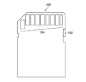
- FIG. 1 Front view of a memory card according to the present invention
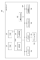
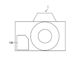
- the block diagram which shows embodiment of the internal structure of the memory card 100 The figure used in order to explain the card coordinate system of memory card 100 External view showing digital camera 1 using memory card 100
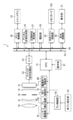
- Block diagram showing the internal structure of the digital camera 1 The figure which shows the arrangement
- FIG. 7 is a chart showing the relationship between the camera coordinate system and the card coordinate system that change with the insertion direction of the memory card 100 shown in FIGS.
- Waveform diagram showing sensor outputs of gyro sensor 140 and acceleration sensor 150 The figure which shows the data area of the flash memory 130 used in order to demonstrate the 1st recording method of a sensor output. The figure which shows the data area of the flash memory 130 used in order to demonstrate the 2nd recording method of sensor output
- FIG. 1 and 2 are external views of a memory card according to the present invention, FIG. 1 is a front view of the memory card, and FIG. 2 is a rear view of the memory card.
- the memory card 100 shown in FIGS. 1 and 2 has the same appearance as an SD memory card (also referred to as an SD card) and can be used as an SD card.
- an SD memory card also referred to as an SD card
- a write prohibition switch 102 is provided on the left side of the memory card 100, and nine terminals 104 are provided on the distal end of the memory card 100 on the insertion direction side.
- FIG. 3 is a block diagram showing an embodiment of the internal structure of the memory card 100.
- a memory card 100 is mainly composed of a CPU (Central Processing Unit) 110, a card interface (card I / F) 120, a memory interface (memory I / F) 122, and a flash memory that is a readable / writable nonvolatile memory. 130, a gyro sensor 140, an acceleration sensor 150, and an electronic compass 160.
- CPU Central Processing Unit
- card I / F card interface
- memory I / F memory interface
- flash memory that is a readable / writable nonvolatile memory.
- the memory card 100 of this example is detachable from an electronic device (photographing device) such as a digital camera, a digital video camera, a smartphone with a camera, a tablet terminal with a camera, or the like that includes at least an imaging unit that captures moving images. It is suitable as an external memory for various types of photographing devices. That is, the memory card 100 records moving image data indicating a moving image taken by the photographing device, and records information on camera shake of the photographing device during moving image detection detected by the memory card 100 itself.
- an electronic device such as a digital camera, a digital video camera, a smartphone with a camera, a tablet terminal with a camera, or the like that includes at least an imaging unit that captures moving images. It is suitable as an external memory for various types of photographing devices. That is, the memory card 100 records moving image data indicating a moving image taken by the photographing device, and records information on camera shake of the photographing device during moving image detection detected by the memory card 100 itself.
- a RAM (Random Access Memory) 116 and a ROM (Read Only Memory) 118 are connected (or built in) to the CPU 110, and the CPU 110 uses the RAM 116 as a work area according to a control program stored in the ROM 118. General control of each part.
- the CPU 110 includes a function as a determination unit 112 that determines the insertion direction of the memory card 100 into the device, and a blur correction unit 114 that corrects blurring of moving images. Details of the determination unit 112 and the shake correction unit 114 will be described later.
- the card I / F 120 includes the nine terminals 104 shown in FIG. 2, and is a part that reads and writes data and exchanges commands with a device to which the memory card 100 is inserted and to which the terminal 104 is connected.
- the memory I / F 122 is a part for writing information to the flash memory 130 and reading information from the flash memory 130 based on an instruction from the CPU 110, and data and addresses with the flash memory 130 through the internal bus 124. Information, status information, commands, etc. are exchanged.
- the gyro sensor 140 detects angular velocities in the directions around the three orthogonal axes.
- An xyz coordinate system of the memory card 100 as shown in FIG. 4 is defined as a card coordinate system.
- the gyro sensor 140 detects an angular velocity around the x axis, an angular velocity around the y axis, and an angular velocity around the z axis, and angular velocity data indicating angular velocities around each of the three orthogonal axes (xyz axes) ( First, second and third sensor outputs).
- the angular velocity detected by the gyro sensor 140 is positive in the direction around the axis indicated by the arrow in FIG.
- the acceleration sensor 150 detects acceleration in each of the three orthogonal axes, and determines the angular velocity in the x-axis direction, the angular velocity in the y-axis direction, and the angular velocity in the z-axis direction of the card coordinate system shown in FIG. Each is detected, and acceleration data (fourth, fifth and sixth sensor outputs) indicating the angular velocity in each axial direction is output.
- the acceleration detected by the acceleration sensor 150 is positive in the direction indicated by the xyz-axis arrow in FIG.
- the electronic compass 160 includes geomagnetic sensors that respectively detect the geomagnetic flux density in each of the three orthogonal axes, and the magnetic flux density in the x-axis direction, the y-axis direction of the card coordinate system shown in FIG.
- the magnetic flux density in the z-axis direction is detected, and geomagnetic data (sensor output) indicating the geomagnetic flux density in each axial direction is output.
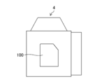
- FIG. 5 is an external view showing an example of a digital camera in which the memory card 100 is used as an external recording medium.
- the XYZ coordinate system of the digital camera 1 as shown in FIG. 5 is defined as the camera coordinate system.
- the camera coordinate system XYZ coordinate system
- the vertical direction is the Y-axis direction
- the optical axis direction of the photographing lens 10 is the Z-axis direction.
- the horizontal direction of the camera 1 and the direction orthogonal to the Y-axis direction and the Z-axis direction is the X-axis direction.
- FIG. 6 is a block diagram showing the internal structure of the digital camera 1.
- the digital camera 1 includes an imaging lens 10 and an imaging device 11 that constitute an imaging unit, a CPU 15, an imaging device driving unit 20, an operation unit 21, an analog signal processing unit 22, and A / D (Analog / Digital).
- a converter 23, a digital signal processing unit 26, a correction lens 41 functioning as a shake correction optical system, a shake correction mechanism 42, a shake control unit 50, a camera shake detection unit 52, and the like are configured.
- Each unit operates under the control of the CPU 15, and the CPU 15 controls each unit of the digital camera 1 by executing a predetermined control program based on an input from the operation unit 21.
- the CPU 15 has a built-in program ROM in which various data necessary for control are recorded in addition to the control program executed by the CPU 15.
- the CPU 15 controls each part of the digital camera 1 by reading the control program recorded in the program ROM into the main memory 24 and sequentially executing the program.
- the main memory 24 is used as a program execution processing area, a temporary storage area for image data, and various work areas.
- the operation unit 21 includes general camera operation means such as a release button, a power switch, a shooting mode dial, and a shake correction switch, and outputs a signal corresponding to the operation to the CPU 15.
- general camera operation means such as a release button, a power switch, a shooting mode dial, and a shake correction switch
- the photographing lens 10 includes a zoom lens and a focus lens (not shown).
- the lens driving unit 18 changes the angle of view by moving the zoom lens back and forth on the optical axis based on a command from the CPU 15, and adjusts the focus by moving the focus lens back and forth on the optical axis. I do.
- the subject light transmitted through the photographing lens 10 is received by the image sensor 11 through the correction lens 41, the diaphragm 12, and the infrared cut filter 14.
- the correction lens 41 is driven by a shake correction mechanism 42.
- the shake correction mechanism 42 supports the correction lens 41 so as to be movable in two orthogonal directions (X direction and Y direction) in a plane perpendicular to the optical axis, and is also corrected by a voice coil motor (not shown). Are moved in the X and Y directions, respectively.
- the camera shake detection unit 52 includes a gyro sensor and an acceleration sensor, and detects camera shake (angular velocity and acceleration) of the digital camera 1.
- the gyro sensor included in the camera shake detection unit 52 detects an angular velocity around each axis of the camera coordinate system, and the angular velocity around the X axis is the angular velocity in the pitch direction of the digital camera 1.
- the angular velocity around the Y axis is the angular velocity in the yaw direction of the digital camera 1
- the angular velocity around the Z axis is the angular velocity in the roll direction of the digital camera 1.
- the acceleration sensor included in the camera shake detection unit 52 detects the acceleration in each axis direction of the camera coordinate system shown in FIG. 5, and the acceleration in the X axis direction is the acceleration in the horizontal direction of the digital camera 1.
- the acceleration in the Y-axis direction is the acceleration in the vertical direction of the digital camera 1, and the acceleration in the direction around the Z-axis is the acceleration in the front-rear direction of the digital camera 1.
- the shake control unit 50 controls the shake correction mechanism 42 so as to move the correction lens 41 in the X and Y directions within a plane perpendicular to the optical axis in accordance with a camera shake detection signal from the camera shake detection unit 52. Details of the blur correction will be described later.
- the aperture drive unit 19 controls the aperture amount of the aperture 12 based on a command from the CPU 15 and adjusts the exposure amount of the image sensor 11 to be an appropriate exposure amount.
- the infrared cut filter 14 removes the infrared component of the subject light incident on the image sensor 11.
- the image sensor 11 is composed of a CMOS (Complementary Metal-Oxide Semiconductor) type color image sensor.
- CMOS Complementary Metal-Oxide Semiconductor
- the image sensor 11 is not limited to the CMOS type, but may be an XY address type or a CCD (Charge-Coupled Device) type image sensor.
- CCD Charge-Coupled Device
- the image sensor 11 is composed of a plurality of pixels arranged in a matrix with a predetermined pattern arrangement (Bayer arrangement, X-Trans (registered trademark) arrangement, honeycomb arrangement, etc.), and each pixel has a microlens, red (R) , Green (G) or blue (B) color filter, and a photoelectric conversion unit (photodiode or the like).
- a predetermined pattern arrangement Bayer arrangement, X-Trans (registered trademark) arrangement, honeycomb arrangement, etc.
- each pixel has a microlens, red (R) , Green (G) or blue (B) color filter, and a photoelectric conversion unit (photodiode or the like).
- the subject light is imaged on the light receiving surface of the image pickup device 11 through the photographing lens 10 and converted into an electric signal by each light receiving device. That is, each pixel of the image sensor 11 accumulates electric charge according to the amount of incident light, and an electric signal according to the amount of electric charge accumulated in each pixel is read from the image sensor 11 as an image signal.
- the image sensor driving unit 20 controls reading of image signals from the image sensor 11 in accordance with instructions from the CPU 15. In addition, the image sensor driving unit 20 discharges charges accumulated in the pixels of the image sensor 11 at the same time (reset all at once) by an electronic shutter control signal from the CPU 15 to start exposure.
- the analog signal processing unit 22 performs various types of analog signal processing on the analog image signal obtained by photographing the subject with the image sensor 11.
- the analog signal processing unit 22 includes a sampling hold circuit, a color separation circuit, an AGC (Automatic Gain Control) circuit, and the like.
- the AGC circuit functions as a sensitivity adjustment unit that adjusts sensitivity at the time of imaging (ISO sensitivity (ISO: International Organization for Standardization)), adjusts the gain of an amplifier that amplifies an input image signal, and the signal level of the image signal is Try to be in the proper range.
- ISO sensitivity ISO: International Organization for Standardization
- the A / D converter 23 converts the analog image signal output from the analog signal processing unit 22 into a digital image signal.
- the analog signal processor 22 and the A / D converter 23 are often built in the image sensor 11.
- the digital signal processing unit 26 In addition to the CPU 15 and the memory control unit 25, the digital signal processing unit 26, the compression / decompression processing unit 27, the integration unit 28, the external memory control unit 30, the display control unit 32, and the like are connected to the control bus 33 and the data bus 34. These are configured to be able to transmit / receive information to / from each other via the control bus 33 and the data bus 34.
- Image data mosaic image data
- the analog signal processing unit 22 and the A / D converter 23 when capturing a still image or a moving image is transmitted via the memory control unit 25.
- Image data mosaic image data
- the main memory 24 is input to the main memory 24 and temporarily stored.
- the digital signal processing unit 26 performs various types of digital signal processing on the image data stored in the main memory 24.
- the digital signal processing unit 26 appropriately reads out image data stored in the main memory 24, and performs offset processing, gain control processing including sensitivity correction, gamma correction processing, demosaicing processing (demosaicing processing, Digital signal processing such as RGB / YCrCb conversion processing is also performed, and the image data after the digital signal processing is stored in the main memory 24 again.
- the demosaic process is a process of calculating color information of all RGB for each pixel from a mosaic image composed of RGB, for example, in the case of an imaging device composed of RGB color filters, and mosaic data (dot sequential RGB data). ) To generate the RGB 3 plane image data.
- the RGB / YCrCb conversion process is a process of converting the synchronized RGB data into luminance data (Y) and color difference data (Cr, Cb).
- the compression / decompression processing unit 27 performs compression processing on the non-compressed luminance data Y and the color difference data Cb, Cr once stored in the main memory 24 at the time of recording a still image or a moving image.
- a still image for example, it is compressed in JPEG (JointoPhotographic coding Experts Group) format, and in the case of a moving image, for example, H.264. Compress in H.264 format.
- the image data compressed by the compression / decompression processing unit 27 is recorded on the memory card 100 via the external memory control unit 30. Further, the compression / decompression processing unit 27 performs decompression processing on the compressed image data obtained from the memory card 100 via the external memory control unit 30 in the reproduction mode, and generates uncompressed image data.
- the accumulating unit 28 takes in R, G, and B image signals stored in the main memory 24 according to a command from the CPU 15 and calculates an accumulated value necessary for AE (Auto-Exposure) control.
- the CPU 15 calculates a luminance value from the integrated value and obtains an exposure value from the luminance value. Further, the aperture value and the shutter speed are determined from the exposure value according to a predetermined program diagram.
- the external memory control unit 30 performs control to record the image data compressed by the compression / decompression processing unit 27 in the memory card 100. Further, the external memory control unit 30 performs control for reading compressed image data from the memory card 100.
- the display control unit 32 performs control for causing the display unit 31 to display uncompressed image data stored in the main memory 24 (or a video memory (not shown)).
- the display unit 31 is configured by a display device such as a liquid crystal display device or organic electroluminescence.
- the digital image signal continuously generated by the digital signal processing unit 26 is temporarily stored in the main memory 24.
- the display control unit 32 converts the digital image signal temporarily stored in the main memory 24 into a display signal format and sequentially outputs it to the display unit 31. Thereby, the captured image is displayed on the display unit 31 in real time, and the display unit 31 can be used as an electronic viewfinder.
- the display unit 31 is also used as a display screen for a user interface.
- the user of the digital camera 1 can switch between the camera shake ON mode and the camera shake OFF mode by the operation unit 21.
- the correction lens 41 is moved and controlled so that subject image blur (image blur) due to camera shake (camera shake) of the digital camera 1 is cancelled.
- the camera shake OFF mode control is performed so that the correction lens 41 remains stopped.
- the camera shake detection unit 52 detects the angular velocities of the digital camera 1 in the direction around the X axis (yaw direction) and the direction around the Y axis (pitch direction). An angular velocity signal indicating is output.
- the shake control unit 50 integrates the angular velocity signals in the pitch direction and the yaw direction input from the camera shake detection unit 52 and an angle signal (pitch angle signal and yaw angle signal) indicating the shake angle in the pitch direction and yaw direction of the digital camera 1. )
- the correction lens 41 is provided via the blur correction mechanism 42 so as to cancel image blur due to camera shake in the pitch direction and yaw direction of the digital camera 1.
- Y direction vertical direction
- X direction horizontal direction
- image blurring that occurs in the digital camera 1 includes, in addition to angular blurring of the digital camera 1, for example, so-called translational blurring that occurs when the digital camera 1 moves in parallel in each axial direction.
- This translation blur tends to increase the image blur as the imaging magnification increases. Therefore, for example, when close-up photography is performed with the digital camera 1 held in hand, it is preferable to correct translational blurring.
- the shake control unit 50 When correcting the translational shake of the digital camera 1, the shake control unit 50 integrates acceleration signals indicating acceleration in the X-axis direction and the Y-axis direction detected by the acceleration sensor of the camera shake detection unit 52 twice.
- the translational blur amount in the X-axis direction and the Y-axis direction is obtained, the blur amount on the imaging surface of the image sensor 11 is calculated from the translational blur amount and the image magnification at the time of shooting, and the blur amount is canceled using the calculated blur amount.
- the correction lens 41 is driven via the blur correction mechanism 42. Accordingly, translational blur can be corrected.
- FIGS. 7 to 11 are diagrams showing examples of the insertion direction of the memory card 100 into a photographing apparatus including a digital camera.
- the memory card 100 is inserted from the bottom side of the digital camera 1, and the front side of the memory card 100 (see FIG. 1) is inserted in a direction that matches the front of the digital camera 1. Yes.
- the angular velocity around the x axis, the angular velocity around the y axis, and the angular velocity around the z axis detected by the gyro sensor 140 of the memory card 100 attached to the digital camera 1 are shown.
- the first, second, and third sensor outputs are respectively the angular velocity in the X-axis direction (pitch direction), the Y-axis direction (yaw direction), and the Z-axis direction (roll) in the XYZ coordinate system of the digital camera 1.
- Direction angular velocity.
- the memory card 100 is inserted from the bottom side of the digital camera 2, and the back side (see FIG. 2) of the memory card 100 is inserted in a direction that matches the front of the digital camera 1. Yes.
- the card coordinate system of the memory card 100 and the camera coordinate system of the digital camera 2 do not coincide with each other.
- the positive and negative of the X-axis direction and the Z-axis direction of the camera coordinate system and the x-axis direction and the z-axis direction of the card coordinate system are opposite to each other.
- the memory card 100 is inserted from the left side of the digital camera 3 in FIG. 9, and the front of the memory card 100 is inserted in a direction that matches the front of the digital camera 1. .
- the card coordinate system of the memory card 100 and the camera coordinate system of the digital camera 3 do not coincide with each other.
- the X-axis direction and the Y-axis direction of the camera coordinate system and the x-axis direction and the y-axis direction of the card coordinate system are interchanged, and the positive and negative in the x-axis direction are reversed.
- the memory card 100 is inserted from the bottom surface side of the digital camera 3, and the front of the memory card 100 is inserted in a direction that coincides with the side surface of the digital camera 1 in FIG. 10.
- the card coordinate system of the memory card 100 and the camera coordinate system of the digital camera 4 do not coincide with each other.
- the X-axis direction and the Z-axis direction of the camera coordinate system are interchanged with the x-axis direction and the z-axis direction of the card coordinate system, and the positive and negative signs in the z-axis direction are reversed.
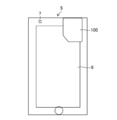
- the memory card 100 is inserted from the upper surface side of the smartphone 5, and the front of the memory card 100 is the back surface of the smartphone 5 (the surface on which the display input unit 6 is provided) in FIG. 11. Inserted in matching orientation.
- an imaging unit (not shown) is provided on the front side of the smartphone 5.
- Reference numeral 7 denotes a self-portrait imaging unit provided on the back side of the smartphone 5.
- the card coordinate system of the memory card 100 and the camera coordinate system of the image pickup unit provided on the front side of the smartphone 5 do not coincide with each other.
- the positive and negative of the Y-axis direction and the Z-axis direction of the camera coordinate system and the y-axis direction and the z-axis direction of the card coordinate system are opposite to each other.
- FIG. 12 is a chart showing the relationship between the camera coordinate system and the card coordinate system that change with the insertion direction of the memory card 100 shown in FIGS.
- the memory card 100 records moving image data indicating a moving image captured by a photographing device such as the digital camera 1 and also includes a recording device that is capturing a moving image and detected by the memory card 100 in association with the moving image data.
- Camera shake information angular velocity data (first, second and third sensor outputs) indicating angular velocities around the respective axes of the card coordinate system detected by the gyro sensor 140
- Acceleration data fourth, fifth and sixth sensor outputs
- the memory card 100 is used in common for various digital cameras 1 to 4 and smartphones 5 and other photographing devices having different insertion directions of the memory card as described above. Which axis around the camera coordinate system the first, second, and third sensor outputs of the gyro sensor 140 are is determined by the direction in which the memory card 100 is inserted into the photographing apparatus. Further, which axial direction of the camera coordinate system the fourth, fifth and sixth sensor outputs of the acceleration sensor 150 are determined by the insertion direction of the memory card 100 into the photographing apparatus.
- the determining unit 112 in the CPU 110 of the memory card 100 shown in FIG. 3 determines the insertion direction of the memory card 100 into the photographing device by the memory card itself.
- FIG. 13 is a diagram illustrating a general posture of the digital camera 1 when shooting a live view image or a moving image.
- the memory card 100 is inserted from the bottom side of the digital camera 1 as in FIG. 7, and the front side of the memory card 100 is inserted in a direction that matches the front of the digital camera 1.
- the gravity of the memory card 100 inserted in the digital camera 1 is compared by comparing the magnitudes of the fourth, fifth and sixth sensor outputs of the acceleration sensor 150 when the digital camera 1 is in the posture shown in FIG.
- the direction can be determined. That is, the relationship between the Y-axis direction corresponding to the gravity direction of the camera coordinate system of the digital camera 1 and the gravity direction of the memory card 100 inserted into the digital camera 1 can be specified.
- FIG. 14 is a diagram illustrating the posture of the digital camera 1 in which the photographing lens 10 is inclined downward.
- the posture of the digital camera 1 shown in FIG. 14 is such that a menu screen is displayed on the display unit 31 (FIG. 6) provided on the back of the digital camera 1 and various setting operations (recording) are performed by the operation unit 21 while viewing the menu screen.
- various setting operations recording
- the display screen of the display unit 31 faces upward, and the taking lens 10 tilts downward.
- gravitational acceleration is applied in the negative y-axis direction and positive z-axis direction of the card coordinate system of the memory card 100, and the acceleration in the x-axis direction is the acceleration associated with translational blurring. Therefore, it is smaller than gravitational acceleration.
- the smallest output of the fourth, fifth and sixth sensor outputs of the acceleration sensor 150 acquired when the digital camera 1 is in the posture shown in FIG. 14 is the memory card 100 inserted in the digital camera 1. This corresponds to acceleration in the X-axis direction (horizontal direction).
- the fourth acceleration indicating the acceleration in each axial direction acquired from the acceleration sensor 150 built in the memory card 100 is shown.
- the relationship (memory card insertion direction) between the camera coordinate system of the digital camera 1 and the card coordinate system of the memory card 100 inserted into the digital camera 1 is specified. can do.
- the determination unit 112 in the CPU 110 of the memory card 100 can determine the insertion direction of the memory card 100 based on the status information of the digital camera 1 and the fourth, fifth, and sixth sensor outputs of the acceleration sensor 150.
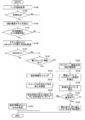
- FIG. 15 is a flowchart showing the determination process of the insertion direction of the memory card 100 according to the first determination method.
- the determination unit 112 in the memory card 100 causes the photographing device to capture a live view image or a moving image. It is determined whether it is in the middle (step S14). If the determination unit 112 can acquire the status information of the imaging device from the imaging device, it can determine whether the live view image or the moving image is being captured from the status information. However, even if the status information of the photographing device cannot be acquired, the moving image data is recorded on the memory card 100 at least during the shooting of the moving image.
- the determination unit 112 determines the acceleration (fourth and fifth) from the acceleration sensor 150 in each axis direction of the card coordinate system (xyz coordinate system). And the sixth sensor output) (step S16). In the determination unit 112, one of the acquired fourth, fifth, and sixth sensor outputs is sufficiently larger than the other two sensor outputs (acceleration is concentrated in one direction). Whether or not (step S18).
- step S18 the direction in which the acceleration is concentrated in one direction is determined as the downward direction (gravity acceleration direction) (step S20).
- One axis direction (direction in which acceleration is concentrated in one direction) of the card coordinate system corresponding to one of the fourth, fifth and sixth sensor outputs is defined as the vertical axis of the camera coordinate system.
- the axial direction is the direction (Y-axis direction). If the acceleration is not concentrated in one direction (in the case of “No”), the gravity acceleration direction is unknown, and the process returns to step S14.
- the determination unit 112 displays a menu screen on the display unit 31 of the digital camera 1 to determine whether the menu is being operated. Alternatively, it is determined whether or not a moving image (video) recorded in the memory card 100 is being reproduced (step S22).
- the determination unit 112 determines the acceleration (fourth and fourth) from the acceleration sensor 150 in each axis direction of the card coordinate system (xyz coordinate system). 5 and 6th sensor output) are acquired (step S24). In the determination unit 112, two sensor outputs of the acquired fourth, fifth, and sixth sensor outputs are sufficiently larger than the other one sensor output (acceleration is concentrated in two directions). Is determined (step S26).
- step S20 When the acceleration is concentrated in two directions (when step S26 is “Yes”), it is further determined whether one of the two directions is determined as the downward direction by step S20 (step S20). S28). If one of the two directions is determined to be the downward direction (when step S28 is “Yes”), the axial direction other than the downward direction of the two directions is set as the axial direction in the front-rear direction of the camera coordinate system. An axial direction with respect to the (Z-axis direction) is set (step S30), and the remaining axial direction is set as an axial direction with respect to the horizontal axis direction (X-axis direction) of the camera coordinate system.
- step S28 the process proceeds to step S22.
- step S14 If it is determined in step S14 that the image is not being shot (step S14 is “No”), the process proceeds to step S40.
- step S40 as in step S22, it is determined whether the menu is being operated or whether the video is being reproduced.
- the determination unit 112 determines the acceleration (fourth and fourth) from the acceleration sensor 150 in each axis direction of the card coordinate system (xyz coordinate system). 5 and 6th sensor output) are acquired (step S42). In the determination unit 112, two sensor outputs of the acquired fourth, fifth, and sixth sensor outputs are sufficiently larger than the other one sensor output (acceleration is concentrated in two directions). Is determined (step S44).
- the determination unit 112 When the acceleration is concentrated in two directions (when Step S44 is “Yes”), the determination unit 112 temporarily stores the two axes of the card coordinate system corresponding to the two directions (Step S46).
- the determination unit 112 determines whether or not shooting is in progress as in step S14 (step S48). When it is determined that shooting is in progress (when step S48 is “Yes”), the acceleration sensor 150 is determined. To obtain the acceleration (fourth, fifth and sixth sensor outputs) in each axial direction of the card coordinate system (step S50). Subsequently, the determination unit 112 determines that one of the acquired fourth, fifth, and sixth sensor outputs is sufficiently larger than the other two sensor outputs (acceleration concentrates in one direction). Whether or not) (step S52).
- step S52 If the acceleration is concentrated in one direction (when step S52 is “Yes”), the direction in which the acceleration is concentrated in one direction is determined as the downward direction (gravity acceleration direction) (step S54).
- One axial direction of the card coordinate system corresponding to one of the fourth, fifth and sixth sensor outputs is defined as an axial direction with respect to the vertical axial direction (Y-axis direction) of the camera coordinate system.
- one of the two direction axes once stored in step S46 is It is determined whether or not the downward direction is determined in step S54 (step S56). If one of the two directions is determined to be the downward direction (when step S56 is “Yes”), the axial direction other than the downward direction of the two directions is the longitudinal axis of the camera coordinate system. It is determined that the direction is the axial direction with respect to the direction (Z-axis direction) (step S58), and the remaining axial direction is set as the axial direction with respect to the lateral direction (X-axis direction) of the camera coordinate system.
- step S56 if “No” is determined in step S56, the process proceeds to step S48.
- the determination unit 112 in the CPU 110 of the memory card 100 shown in FIG. 3 acquires device information of the photographing device, and acquires information on the insertion direction of the memory card 100 through the network based on the acquired device information.
- the determination unit 112 may directly acquire the device information of the photographing device in which the memory card 100 is inserted from the photographing device, or the moving image file or the still image data of the moving image data recorded on the memory card 100 by the photographing device. You may make it acquire the apparatus information of the imaging device which image
- the still image file is generally recorded as an image file in the Exif (Exchangeable Image File Format) file format.
- Exif information such as shooting date and time, model name, manufacturer, number of pixels, aperture value, and shutter speed is recorded as header information. Therefore, the model information (device information) can be acquired from the header information (Exif information) of the still image file.
- photographed the moving image is recorded on the header information of a moving image file, it is preferable to acquire the information (apparatus information) of a model from the header information of a moving image file.
- the determination unit 112 acquires device information of the image capturing device and the memory card 100 is in an environment where the service server that provides the search site or the device information can be accessed through the network (Internet), the image capturing is performed based on the acquired device information.
- Information on the insertion direction of the memory card 100 into the device is searched, or information on the insertion direction of the memory card 100 is acquired from the service server.
- the memory card 100 is in an environment where a search site on the Internet can be accessed, for example, when the photographing device is the smartphone 5, it can be connected to the Internet via the carrier communication network of the smartphone 5.
- the case may be the case where the memory card 100 is inserted into a card slot of a personal computer or the like connected to the Internet.
- An electronic compass 160 is built in the memory card 100 shown in FIG.
- the electronic compass 160 includes geomagnetic sensors that respectively detect the geomagnetic flux density in each of the three orthogonal axes, and the magnetic flux density in the x-axis direction, the y-axis direction of the card coordinate system shown in FIG.
- the magnetic flux density in the z-axis direction is detected, and geomagnetic data (sensor output) indicating the geomagnetic flux density in each axial direction is output.
- the discriminating unit 112 discriminates the insertion direction of the memory card 100 based on the sensor output indicating the magnetic flux density detected by the electronic compass 160.
- the photographing device is swung from east to north, and stopped so that the front of the photographing device faces north (the photographing direction faces north).
- the discriminating unit 112 acquires the geomagnetic data (sensor output) in each axial direction of the card coordinate system detected by the electronic compass 160 from the electronic compass 160 when the photographing apparatus is swung as described above, and the acquired sensor By analyzing the output, the insertion direction of the memory card 100 inserted in the photographing apparatus is determined.
- the sensor output in two directions among the sensor outputs in each axis direction of the card coordinate system of the electronic compass 160 greatly fluctuates.
- the two directions in which the sensor output greatly varies can be determined as corresponding to the X-axis direction and the Z-axis direction of the camera coordinate system.
- any one of the two directions in which the sensor output greatly varies is the camera coordinate system. You can see if it corresponds to the Z-axis direction.
- the imaging device since the magnetic flux density is detected as a vector quantity having a magnitude and direction, the imaging device is swung from the east to the north (the imaging device is yawed in the positive direction), and greatly Based on the sensor output in two directions that fluctuate, the correspondence between each axis direction of the card coordinate system and each axis direction of the camera coordinate system (that is, the insertion direction of the memory card 100 inserted in the photographing apparatus) can be known.
- first, second, and third sensor outputs detected by the gyro sensor 140 are acquired, and the gyro sensor The first, second, and third sensor outputs detected by 140 may be used to determine the insertion direction of the memory card 100 inserted in the photographing apparatus.
- guidance may be intentionally issued so as to swing the photographing device, or processing may be automatically entered when a swing is detected.
- the determination unit 112 determines the photographing apparatus acquired when the photographing apparatus is swung.
- the insertion direction of the memory card 100 can be determined by matching the sensor output indicating the azimuth direction with the first, second, and third sensor outputs detected by the gyro sensor 140.
- the Y axis around the shooting device The sensor output corresponding to the angular velocity in the direction can be determined. Further, the angular velocity in the X-axis direction and the Z-axis direction of the photographic device is determined from this determination result and the first, second, and third sensor outputs of the gyro sensor 140 when the photographic device is pitched or rolled, for example. The corresponding sensor output can be determined.
- the blur correction unit 114 shown in FIG. 3 corrects the blur of the moving image recorded in the flash memory 130 based on the first, second, and third sensor outputs of the gyro sensor 140 recorded together with the moving image. is there.
- the insertion direction of the memory card 100 is assumed and assumed.
- Blur correction is performed using the first, second and third sensor outputs corresponding to the insertion direction.
- the shake correction unit 114 outputs the first, second, and third sensor outputs of the gyro sensor 140, respectively. It is applied as acceleration data in the direction around the X axis, the direction around the Y axis, and the direction around the Z axis in the camera coordinate system, and blur correction is performed.
- the determination unit 112 calculates the blur amount of the moving image corrected by the shake correcting unit 114 by image processing, and assumes that the moving image corrected by the shake correcting unit 114 is the smallest based on the assumed insertion direction.
- the inserted direction is determined as the insertion direction of the memory card 100 with respect to the photographing device.
- the blur correction unit 114 does not need to reproduce a moving image, for example, two images having different times in the moving image, and the first and second gyro sensors detected corresponding to these two images, Based on the second and third sensor outputs, the blur (deviation amount) between the two images may be corrected.
- FIG. 16 is a flowchart showing a determination process of the insertion direction of the memory card 100 according to the second determination method to the fourth determination method.
- the determination unit 112 acquires the header information of the moving image file recorded in the flash memory 130 and the model name of the photographing device and the like (step S100). If the model name of the photographing device is not recorded as the header information, the header information (Exif tag information) of the still image file recorded together with the moving image file may be acquired. This is because the Exif tag information records the model name of the photographing device.
- step S102 it is determined whether or not acquisition of desired header information has succeeded. If the acquisition is successful (step S102 is “Yes”), the model name of the imaging device is extracted from the header information. (Step S104).
- step S106 it is determined whether the device used can connect to the Internet.
- the case where the device used can be connected to the Internet includes the case where the memory card 100 can be connected to the Internet via a personal computer or the like in addition to the case where the photographing device can be connected to the Internet.
- step S106 If it is determined in step S106 that the device in use is connectable to the Internet (when step S106 is “Yes”), the insertion direction of the memory card 100 with respect to the imaging device is determined based on the model name of the imaging device. Search through (step S108). If the search is successful (step S110), the insertion direction of the memory card 100 with respect to the photographic device is set based on the search information (step S190).
- step S102 determines whether or not the photographing apparatus has an electronic compass function (step S112). If it is determined that the photographing apparatus has the electronic compass function (when Step S112 is “Yes”), for example, the photographing apparatus is swung in the yawing direction and the pitching direction (Step S116). A change in the azimuth direction during the swing in the yawing direction of the photographing apparatus is confirmed (step S118), and based on matching between the change in the azimuth direction and changes in the first, second, and third sensor outputs of the gyro sensor 140. Then, the insertion direction of the memory card 100 with respect to the photographing device is determined (step S120).
- step S112 If it is determined in step S112 that there is no electronic compass function, the process proceeds to step S122.
- step S122 the live view image and the sensor output of the gyro sensor 140 are acquired, and the live view image and sensor output for a short time are temporarily stored in the flash memory 130 (or RAM 116).
- the blur correction unit 114 assumes one direction out of all possible directions of insertion of the memory card 100, stores the live view image, and the sensor output of the gyro sensor 140 corresponding to the assumed insertion direction. Based on the above, the blur of the live view image is temporarily corrected (step S124), and the determination unit 112 calculates the blur amount of the live view image after the temporary correction (step S126).
- step S1228 it is determined whether or not the processing of step S124 and step S126 has been performed for all directions in the insertion direction.
- FIG. 17 is a diagram showing the relationship between the camera coordinate system (XYZ coordinate system), the angular velocity around each axis in the camera coordinate system, and the acceleration in each axis direction.
- the camera coordinate system is as defined in FIG.
- the angular velocity in the Y axis direction (yaw direction) of the camera coordinate system is a
- the angular velocity in the X axis direction (pitch direction) is b
- the angular velocity in the Z axis direction (roll direction) is c
- the acceleration in the X-axis direction is d
- the acceleration in the Y-axis direction is e
- the acceleration in the Z-axis direction is f.
- FIG. 18 is a waveform diagram showing sensor outputs of the gyro sensor 140 and the acceleration sensor 150.
- the first, second, and third sensor outputs of the gyro sensor 140 shown in FIG. 18 are angular velocity data indicating angular velocities around the respective axes of the card coordinate system (xyz coordinate system defined in FIG. 4).
- the fourth, fifth, and sixth sensor outputs 150 are acceleration data indicating the acceleration in each axis direction of the card coordinate system.
- FIG. 19 is a diagram showing a data area of the flash memory 130.
- data areas A, B, and C of the flash memory 130 are areas for recording angular velocities a, b, and c in directions around the respective axes (yaw direction, pitch direction, roll direction) of the camera coordinate system.
- D, E, and F are areas for recording accelerations d, e, and f in the respective axis directions (left-right direction, up-down direction, and front-rear direction) of the camera coordinate system.
- the 1st recording part comprised by CPU110 and memory I / F122 records the moving image file which shows the moving image imaged with the imaging device on the flash memory 130.
- FIG. 1st recording part comprised by CPU110 and memory I / F122 records the moving image file which shows the moving image imaged with the imaging device on the flash memory 130.
- the second recording unit configured by the CPU 110 and the memory I / F 122 determines which of the first, second, and third sensor outputs of the gyro sensor 140 is based on the determination result of the insertion direction of the memory card 100. Since it can be determined whether the angular velocities are in the yaw direction, the pitch direction, and the roll direction, these first, second, and third sensor outputs are recorded in the corresponding areas of the data areas A, B, and C of the flash memory 130, respectively. .
- the fourth, fifth, and sixth sensor outputs of the acceleration sensor 150 is the acceleration in the horizontal direction, the vertical direction, and the front-back direction.
- These fourth, fifth and sixth sensor outputs are recorded in the corresponding areas of the data areas D, E and F of the flash memory 130, respectively.
- the data format for storing the sensor output may be written and saved in a text file or may be saved in a binary format.
- a time code indicating the passage of time from the start of shooting of the moving image is recorded together with the moving image data. Therefore, it is preferable to record the first to sixth sensor outputs according to the same time code.
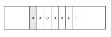
- FIG. 20 is a diagram showing a data area of the flash memory 130.
- data areas A, B, and C of the flash memory 130 are areas for recording the first, second, and third sensor outputs detected by the gyro sensor 140, and the data areas D, E, and F are The areas for recording the fourth, fifth, and sixth sensor outputs detected by the acceleration sensor 150 are used.
- the data area X of the flash memory 130 shown in FIG. 20 is an area for recording information indicating the insertion direction of the memory card 100 with respect to the photographing apparatus.
- the first recording unit configured by the CPU 110, the memory I / F 122, and the flash memory 130 records a moving image file indicating a moving image captured by the photographing device in the flash memory 130.
- the second recording unit including the CPU 110, the memory I / F 122, and the flash memory 130 outputs the first, second, and third sensor outputs of the gyro sensor 140 to the data areas A, B, C, and the fourth, fifth, and sixth sensor outputs of the acceleration sensor 150 are recorded in the data areas D, E, and F, respectively.
- the third recording unit configured by the CPU 110, the memory I / F 122, and the flash memory 130 records information indicating the insertion direction of the memory card 100 with respect to the photographing device in the data area X of the flash memory 130.
- the information indicating the insertion direction of the memory card 100 may be any information as long as it can specify the correspondence between the camera coordinate system and the card coordinate system.
- the third recording unit information (address) indicating which of the data areas A, B, and C of the flash memory 130 is recorded with the angular velocities in the yaw direction, the pitch direction, and the roll direction of the photographing device is recorded.
- Information indicating in which of the data areas D, E, and F of the flash memory 130 the accelerations in the horizontal direction, the vertical direction, and the longitudinal direction are respectively recorded ( Dress) may also be recorded.
- the digital camera 1 shown in FIGS. 5 and 6 also functions as a moving image playback device according to the present invention.
- the digital camera 1 can reproduce a still image or a moving image recorded in the memory card 100 by selecting a reproduction mode by operating the operation unit 21 or the like. Further, when playing back a moving image recorded on the memory card 100, a playback mode in which the motion blur is corrected and played back and a playback mode in which the motion blur is not corrected are operated by operating the operation unit 21 or the like. It can be selected.
- a playback mode in which the motion blur is corrected and played back and a playback mode in which the motion blur is not corrected are operated by operating the operation unit 21 or the like. It can be selected.
- a moving image is reproduced by correcting blurring of the moving image recorded in the memory card 100 will be described.
- the digital camera 1 reads the selected moving image file from the memory card 100 and the CPU 15 and the external memory control unit 30 functioning as an information acquisition unit.
- the compressed moving image data of the read moving image file is expanded by the compression / decompression processing unit 27 and temporarily stored in the main memory 24.
- the information acquisition unit is information of camera shake recorded in the memory card 100 in association with the read moving image file (first, second and third sensor outputs of the gyro sensor 140, fourth and fourth of the acceleration sensor 150). 5th and 6th sensor outputs) and information indicating the insertion direction of the memory card 100 are read out and temporarily stored in the main memory 24.
- the digital signal processing unit 26 functioning as a blur correction unit first reads the first, second and third sensor outputs of the read gyro sensor 140 based on the information indicating the insertion direction of the memory card 100, and reads the moving image Assigned to sensor outputs corresponding to the yaw direction, pitch direction, and roll direction, and the fourth, fifth, and sixth sensor outputs of the read acceleration sensor 150 correspond to the horizontal direction and vertical direction of the read moving image. Assign to sensor output.
- the digital signal processing unit 26 uses the allocated sensor outputs, respectively, to blur the yaw direction, pitch direction, and roll direction (angle blur) of the moving image, and to blur the left and right direction and vertical direction (translational blur) of the moving image. to correct.
- the sensor output (angular velocity) assigned to the pitch direction among the first, second, and third sensor outputs of the gyro sensor 140 is integrated to obtain the shake angle in the pitch direction. Is calculated. Based on the calculated blur angle and the focal length of the taking lens 10 (for example, using the focal length at the time of moving image capturing recorded in the header portion of the moving image file), the vertical direction on the surface of the image sensor 11 is determined. The number of pixels corresponding to the amount of blur is calculated, and the angle blur in the pitch direction is corrected by shifting the frame constituting the moving image by the calculated number of pixels.
- the sensor output (acceleration) assigned to the vertical direction among the fourth, fifth, and sixth sensor outputs of the acceleration sensor 150 is integrated to obtain the translational shake in the vertical direction. Is calculated. Based on the calculated translational blur and the focal length and subject distance of the taking lens 10 (for example, using the focal length and subject distance at the time of moving image recording recorded in the header portion of the moving image file) The number of pixels corresponding to the amount of translational blur in the vertical direction above is calculated, and the translational blur in the vertical direction is corrected by shifting the frame constituting the moving image by the calculated number of pixels.
- the video signal indicating the moving image in which the angle blur and the translational blur are corrected in this way is output to the display unit 31 via the display control unit 32 (output unit) and reproduced as a moving image, or a video output terminal (not shown) Is output to an external display device such as a liquid crystal television via the output unit) and reproduced as a moving image.
- the smartphone 5 illustrated in FIG. 11 there are a case where a moving image is taken horizontally and a case where the moving image is taken vertically, and the smartphone 5 stores information indicating the rotation direction of the smartphone 5 (electronic device) when the moving image is captured as a moving image file. Is recorded in the header part.
- the information indicating the rotation direction refers to, for example, information indicating the rotation position of horizontal shooting, the rotation position of vertical shooting rotated 90 ° right from the state of horizontal shooting, or the rotation position of vertical shooting rotated 90 ° left. .
- the information indicating the rotation direction is the rotation position of the vertical shooting by the smartphone 5 illustrated in FIG. 11, the rotation position of the horizontal shooting rotated 90 degrees right from the rotation position, and 90 ° It is the information which shows the rotation position of the horizontal shooting rotated left.
- the moving image reproducing apparatus When the moving image reproducing apparatus reproduces a moving image shot by a shooting device such as the smartphone 5, the moving image reproducing device acquires information indicating the rotation direction of the shooting device at the time of shooting the moving image.
- the shake correction unit outputs the sensor outputs of the gyro sensor 140 and the acceleration sensor 150 based on the information indicating the rotation direction of the photographing device, the yaw direction of the moving image, the pitch direction, Assigned to the sensor output corresponding to the roll direction and the sensor output corresponding to the horizontal direction and vertical direction of the moving image, and using the assigned sensor output, the angle blur in the yaw direction, pitch direction and roll direction of the moving image and the left and right of the moving image Correct translational blur in direction and up / down direction.
- a moving image may be image
- Information of the imaging unit indicating which imaging unit among the provided imaging units is recorded in the header portion of the moving image file.
- the shake correction unit Sensors indicating the angular velocities corresponding to the yaw direction, the pitch direction, and the roll direction of the moving image, based on the information indicating the insertion direction of 100 and the information of the imaging unit for self-shooting, and the sensor outputs of the gyro sensor 140 and the acceleration sensor 150 Assigned to the output and the sensor output indicating the acceleration corresponding to the horizontal direction and vertical direction of the video, and using the assigned sensor output, the angle blur in the yaw direction, pitch direction and roll direction of the video and the horizontal direction and vertical direction of the video Correct translational blur in the direction.
- the digital camera 1 shown in FIG. 6 has a camera shake correction function, when the camera shake ON mode is selected at the time of shooting a movie and a movie with a corrected camera shake is shot, the memory card It is preferable not to record camera shake information.
- the memory card 100 of the present embodiment includes the gyro sensor 140, the acceleration sensor 150, and the electronic compass 160, but the memory card according to the present invention only needs to include at least the gyro sensor. If the acceleration sensor is not provided, the angular velocity information is not recorded in the memory card, and the translational blur of the moving image cannot be corrected. However, since a normal moving image has a small translational blur with respect to an angular blur, even a memory card without an acceleration sensor can reproduce a moving image with almost no blur.
- the determination unit of the present embodiment has a determination function of determining the insertion direction of the memory card with respect to the photographing apparatus by a plurality of determination methods, but is not limited thereto, and the insertion direction is determined by one or more determination methods. It is sufficient if it has a discriminating mechanism.
- a moving image reproducing apparatus that reproduces a moving image recorded on a memory card by performing shake correction using information on camera shake is not limited to the one provided in the photographing device, and has, for example, a photographing function such as a personal computer. Needless to say, you may not have it.
- the memory card according to the present invention is not limited to the one having the same appearance as the SD card of the present embodiment, but can be applied to memory cards having various appearances.
Landscapes
- Engineering & Computer Science (AREA)
- Multimedia (AREA)
- Signal Processing (AREA)
- Studio Devices (AREA)
- Television Signal Processing For Recording (AREA)
- Adjustment Of Camera Lenses (AREA)
Abstract
動画を撮像する撮像部を備えた種々の電子機器に適用することができ、かつ記録した動画のブレを容易に補正可能なメモリカード及び動画再生装置を提供する。少なくとも動画を撮像する撮像部を備えた電子機器に着脱可能なメモリカード(100)において、直交3軸の各軸回り方向の角速度をそれぞれ検出するジャイロセンサ(140)と、電子機器により撮像された動画を記録する第1の記録部と、ジャイロセンサ(140)により検出された直交3軸の各軸回り方向の角速度を示す第1、第2及び第3のセンサ出力を、第1の記録部に記録する動画に関連付けてそれぞれ記録する第2の記録部と、電子機器に装着されたメモリカードの電子機器に対する挿入方向を判別する判別部(112)と、判別部(112)により判別した挿入方向を示す情報を記録する第3の記録部と、を備える。
Description
本発明はメモリカード及び動画再生装置に係り、特に動画を記録する際に手ブレの情報を記録可能なメモリカード及びそのメモリカードに記録された動画を再生する動画再生装置に関する。
カメラやスマートフォンの手ブレ補正の方法としては、内蔵のジャイロセンサや加速度センサのセンサ情報を手ブレの情報として利用したり、映像解析で得た動きベクトルの情報を利用したりして補正を実施する方法が一般的である。最近、デジタルカメラのホットシューに装着するアクセサリ、又はカメラに装着されるメモリカード(SDカード)内にジャイロセンサや加速度センサを内蔵し、映像とともにセンサ情報を記録しておき、後からセンサ情報を元にパーソナルコンピュータによるソフトウェア処理等で映像のブレを補正する方法が提案されている(非特許文献1)。
特許文献1には、ジャイロセンサを内蔵したメモリカード、及びそのメモリカードを使用して光軸の傾きを検出する撮影装置(携帯電話機)が記載されている。この撮影装置は、メモリカードに内蔵されたジャイロセンサのセンサ情報に基づいて、被写体(例えば、花)の撮影時の撮影光軸の傾き情報を検出し、その傾き情報(花の咲く方向)を被写体情報検索の検索キーとするものである。
ジャイロセンサ内蔵SDカード、インターネット<URL:http://gigazine.net/news/20160809-virtualgimbal-mft2016/>
カメラのホットシューのアクセサリ内にジャイロセンサ等を内蔵する場合、どのような機種であってもアクセサリを取り付ける位置や向きは、ある程度同じになるので問題は無い。しかし、SDカードの場合、機器によって挿入する向きや場所が異なるため、同じブレを機器に加えたとしても、ジャイロセンサや加速度センサから得られるセンサ情報の向きや値が機器により変わってしまう(補正性能に影響が生じる)という問題がある。
したがって、非特許文献1に記載のジャイロセンサ内蔵のSDカードは、SDカードの挿入方向がそのSDカードに対応する機器に対しては使用することができるが、SDカードの挿入方向が異なる種々の機器に対して共通に使用することができないという問題がある。
また、特許文献1に記載のジャイロセンサを内蔵したメモリカードは、映像のブレを補正するために使用されるものではなく、また、センサ情報も記録していない。更に、特許文献2には、メモリカードの挿入方向に関する記載もない。
本発明はこのような事情に鑑みてなされたもので、少なくとも動画を撮像する撮像部を備えた種々の電子機器に適用することができ、かつ記録した動画のブレを容易に補正可能なメモリカード及び動画再生装置を提供することを目的とする。
上記目的を達成するために本発明の一の態様は、少なくとも動画を撮像する撮像部を備えた電子機器に着脱可能なメモリカードにおいて、直交3軸の各軸回り方向の角速度をそれぞれ検出するジャイロセンサと、電子機器により撮像された動画を記録する第1の記録部と、ジャイロセンサにより検出された直交3軸の各軸回り方向の角速度を示す第1、第2及び第3のセンサ出力を、第1の記録部に記録する動画に関連付けてそれぞれ記録する第2の記録部と、電子機器に装着されたメモリカードの電子機器に対する挿入方向を判別する判別部と、判別部により判別した挿入方向を示す情報を記録する第3の記録部と、を備える。
本発明の一の態様によれば、電子機器により撮像された動画を記録し、かつ、内蔵されたジャイロセンサにより検出された直交3軸の各軸回り方向の角速度を示す第1、第2及び第3のセンサ出力を、動画に関連付けてそれぞれ記録する。更に、判別部により電子機器に装着されたメモリカードの電子機器に対する挿入方向を判別し、その判別結果(挿入方向を示す情報)を記録する。これにより、メモリカードに記録された動画を再生する際に、ジャイロセンサにより検出された第1、第2及び第3のセンサ出力を使用して動画のブレを補正して再生することが可能であり、特に挿入方向を示す情報から第1、第2及び第3のセンサ出力が、それぞれ電子機器のヨー方向、ピッチ方向及びロール方向のうちのどの方向の角速度(正負の方向も含む)であるかが分かるため、第1、第2及び第3のセンサ出力を使用して、動画のブレを適切に補正することが可能である。
本発明の他の態様は、少なくとも動画を撮像する撮像部を備えた電子機器に着脱可能なメモリカードにおいて、直交3軸の各軸回り方向の角速度をそれぞれ検出するジャイロセンサと、電子機器により撮像された動画を記録する第1の記録部と、ジャイロセンサにより検出された直交3軸の各軸回り方向の角速度を示す第1、第2及び第3のセンサ出力を、第1の記録部に記録する動画に関連付けてそれぞれ記録する第2の記録部と、電子機器に装着されたメモリカードの電子機器に対する挿入方向を判別する判別部と、を備え、第2の記録部は、判別部により判別した挿入方向に基づいて第1、第2及び第3のセンサ出力を、それぞれヨー方向、ピッチ方向及びロール方向に割り当てられたデータ領域に記録する。
本発明の他の態様によれば、電子機器により撮像された動画を記録し、かつ、内蔵されたジャイロセンサにより検出された直交3軸の各軸回り方向の角速度を示す第1、第2及び第3のセンサ出力を、動画に関連付けてそれぞれ記録する。特に判別部により電子機器に装着されたメモリカードの電子機器に対する挿入方向を判別し、その判別結果に基づいてジャイロセンサの第1、第2及び第3のセンサ出力を、それぞれヨー方向、ピッチ方向及びロール方向に割り当てられたデータ領域に記録するようにしたため、メモリカードに記録された動画を再生する際に、ヨー方向、ピッチ方向及びロール方向に割り当てられたデータ領域に記録された、第1、第2及び第3のセンサ出力を使用して動画のブレを適切に補正して再生することが可能である。
本発明の更に他の態様に係るメモリカードにおいて、直交3軸の各軸方向の加速度をそれぞれ検出する加速度センサを備え、第2の記録部は、加速度センサにより検出された直交3軸の各軸方向の加速度を示す第4、第5及び第6のセンサ出力を、第1の記録部に記録する動画に関連付けてそれぞれ記録することが好ましい。これにより、電子機器の左右方向、上下方向及び前後方向の加速度に起因する動画のブレの補正も可能である。尚、加速度センサの第4、第5及び第6のセンサ出力が、電子機器の左右方向、上下方向及び前後方向のいずれの方向の加速度であるかは、メモリカードの挿入方向を示す情報から分かる。
本発明の更に他の態様に係るメモリカードにおいて、直交3軸の各軸方向の加速度をそれぞれ検出する加速度センサを備え、第2の記録部は、判別部により判別した挿入方向に基づいて加速度センサにより検出された直交3軸の各軸方向の加速度を示す第4、第5及び第6のセンサ出力を、それぞれ動画の左右方向、上下方向及び前後方向に割り当てられたデータ領域に記録することが好ましい。これにより、電子機器の左右方向、上下方向及び前後方向の加速度に起因する動画のブレの補正も可能である。
本発明の更に他の態様に係るメモリカードにおいて、判別部は、電子機器による動画の撮像時に加速度センサから得られる第4、第5及び第6のセンサ出力と、電子機器の背面の表示器の使用時に加速度センサから得られる第4、第5及び第6のセンサ出力とに基づいて挿入方向を判別することが好ましい。
電子機器により動画を撮像する場合、加速度センサから得られる第4、第5及び第6のセンサ出力のうちの最大のセンサ出力は、重力方向の加速度であるため、電子機器に挿入されたメモリカードの重力方向と、加速度センサの直交3軸のうちの1つの軸方向との関係が分かる。また、電子機器の背面の表示器の使用時(例えば、表示器にメニュー画面を表示させて各種の設定を行う操作時、あるいは表示器に動画を再生させる時等)には、表示画面が上向きになるため、このときに加速度センサから得られる第4、第5及び第6のセンサ出力のうちの最小のセンサ出力は、重力方向の加速度が作用しない、水平方向の加速度に対応するセンサ出力である。したがって、動画撮像時及び動画撮像時以外での表示器の使用時に加速度センサから得られる第4、第5及び第6のセンサ出力に基づいて、電子機器に挿入されたメモリカードの挿入方向を判別することができる。
本発明の更に他の態様に係るメモリカードにおいて、判別部は、電子機器の機器情報に基づいてネットワークを通じて挿入方向の情報を取得することが好ましい。メモリカードが装着された電子機器の機器情報を入手することができれば、ネットワーク(インターネット)に接続し、入手した電子機器の機器情報のメモリカードの挿入方向を検索し、又はメモリカードの挿入方向を通知するサービスサーバにアクセスし、電子機器の機器情報に基づいてサービスサーバからメモリカードの挿入方向の情報を取得することができる。
本発明の更に他の態様に係るメモリカードにおいて、電子コンパスを更に備え、判別部は、電子コンパスにより検出される磁束密度を示すセンサ出力、又は電子コンパスにより検出される磁束密度を示すセンサ出力とジャイロセンサにより検出される第1、第2及び第3のセンサ出力とに基づいて挿入方向を判別することが好ましい。例えば、電子機器をスイングして電子機器の正面を北向きになるように停止させた場合に電子コンパスにより検出される磁束密度を示すセンサ出力(の変化)に基づいて電子機器に挿入されたメモリカードの挿入方向を判別することができる。また、電子機器をスイングしたときにジャイロセンサで検出した第1、第2及び第3のセンサ出力を併用して電子機器に挿入されたメモリカードの挿入方向を判別してもよい。
本発明の更に他の態様に係るメモリカードにおいて、電子機器は電子コンパスを備え、判別部は、電子コンパスにより検出される方位方向を示すセンサ出力とジャイロセンサにより検出される第1、第2及び第3のセンサ出力とに基づいて挿入方向を判別することが好ましい。電子機器が電子コンパスを備えている場合には、判別部は、電子機器をスイングしたときに取得される電子機器の方位方向を示すセンサ出力と、ジャイロセンサにより検出される第1、第2及び第3のセンサ出力とのマッチングによりメモリカードの挿入方向を判別することができる。
本発明の更に他の態様に係るメモリカードにおいて、第1の記録部に記録された動画と第2の記録部に記録された第1、第2及び第3のセンサ出力とに基づいて動画のブレ補正を行うブレ補正部を備え、判別部は、挿入方向を仮定し、仮定した挿入方向に基づいてブレ補正部により補正された動画のブレが最も小さくなるときの仮定した挿入方向を、メモリカードの電子機器に対する挿入方向と判別することが好ましい。尚、ブレ補正部は、動画を再生する必要がないため、例えば、動画中の時刻の異なる2枚の画像と、これらの2枚の画像に対応して検出されたジャイロセンサの第1、第2及び第3のセンサ出力とに基づいて、メモリカードの挿入方向を仮定してブレ補正した2枚の画像のブレ(ずれ量)が最小になるときの挿入方向を、メモリカードの電子機器に対する挿入方向と判別することができる。
本発明の更に他の態様に係る動画再生装置は、前述のメモリカードから動画、第1、第2及び第3のセンサ出力、及び挿入方向を示す情報を取得する情報取得部と、取得した挿入方向を示す情報に基づいて第1、第2及び第3のセンサ出力を、取得した動画のヨー方向、ピッチ方向及びロール方向に対応するセンサ出力に割り当て、割り当てられたセンサ出力をそれぞれ使用して、動画のヨー方向、ピッチ方向及びロール方向のブレを補正するブレ補正部と、ブレ補正部によりブレを補正した動画を出力する出力部と、を備える。
本発明の更に他の態様によれば、メモリカードに記録された動画、ジャイロセンサの第1、第2及び第3のセンサ出力、及びメモリカードの挿入方向を示す情報を取得する。メモリカードの挿入方向を示す情報に基づいて、ジャイロセンサの第1、第2及び第3のセンサ出力と、メモリカードが装着された電子機器のヨー方向、ピッチ方向及びロール方向との関係を特定することができるため、第1、第2及び第3のセンサ出力を、動画のヨー方向、ピッチ方向及びロール方向に対応するセンサ出力に割り当てて、動画のブレを補正することができる。
本発明の更に他の態様に係る動画再生装置において、情報取得部は、動画の撮像時の電子機器の回転方向を示す情報を取得し、ブレ補正部は、取得した挿入方向を示す情報及び回転方向を示す情報に基づいて第1、第2及び第3のセンサ出力を、取得した動画のヨー方向、ピッチ方向及びロール方向に対応するセンサ出力に割り当て、割り当てられたセンサ出力を使用して動画のヨー方向、ピッチ方向及びロール方向のブレを補正することが好ましい。
動画の撮像時の電子機器の回転方向を示す情報とは、横撮りと縦撮り(例えば、横撮りの状態から90°右回転又は左回転させた撮影状態)である。横撮りと縦撮りとでは、電子機器のヨー方向、ピッチ方向及びロール方向が異なるため(ヨー方向とピッチ方向とが入れ替わるため)、横撮りと縦撮りとでは、ヨー方向及びピッチ方向にそれぞれ対応するセンサ出力を入れ替えて動画のブレ補正に使用する。
本発明の更に他の態様に係る動画再生装置において、情報取得部は、電子機器の前面及び背面に設けられた撮像部のうちの動画を撮像した撮像部の情報を取得し、ブレ補正部は、取得した挿入方向を示す情報及び撮像部の情報に基づいて第1、第2及び第3のセンサ出力を、取得した動画のヨー方向、ピッチ方向及びロール方向に対応するセンサ出力に割り当て、割り当てられたセンサ出力を使用して動画のヨー方向、ピッチ方向及びロール方向のブレを補正することが好ましい。
スマートフォン等の電子機器は、機器の前面に設けられた撮像部の他に、機器の背面に自分撮りのための撮像部が設けられている。この場合、動画を撮像した撮像部の情報を取得し、特に背面の撮像部により動画が撮影された場合には、電子機器のヨー方向、ピッチ方向及びロール方向が異なるため(ヨー方向とピッチ方向との正負が入れ替わるため)、ヨー方向及びピッチ方向にそれぞれ対応するセンサ出力の正負を入れ替えて動画のブレ補正に使用する。
本発明によれば、ジャイロセンサ付きのメモリカードに、電子機器へのメモリカードの挿入方向を判定する機能を設けるようにしたため、メモリカードに記録した動画のヨー方向、ピッチ方向及びロール方向のブレと、直交3軸のジャイロセンサの各軸回り方向のセンサ出力との対応関係を特定することができる。これにより、メモリカードの挿入方向が異なる種々の電子機器に対して同一のメモリカードを適用した場合であっても、メモリカードに記録したジャイロセンサのセンサ出力を使用して、動画のブレを容易に且つ適切に補正することができる。
以下、添付図面に従って本発明に係るメモリカード及び動画再生装置の好ましい実施の形態について説明する。
<メモリカードの外観>
図1及び図2はそれぞれ本発明に係るメモリカードの外観図であり、図1はメモリカードの正面図であり、図2はメモリカードの背面図である。
図1及び図2はそれぞれ本発明に係るメモリカードの外観図であり、図1はメモリカードの正面図であり、図2はメモリカードの背面図である。
図1及び図2に示すメモリカード100は、SDメモリカード(SDカードともいう)と同じ外観を有し、かつSDカードとして使用可能なものである。
図1上で、メモリカード100の左側部には、書込み禁止スイッチ102が設けられ、メモリカード100の背面の挿入方向側の先端部には、9つの端子104が設けられている。
<メモリカードの内部構造>
図3はメモリカード100の内部構造の実施形態を示すブロック図である。
図3はメモリカード100の内部構造の実施形態を示すブロック図である。
図3に示すようにメモリカード100は、主としてCPU(Central Processing Unit)110、カードインターフェース(カードI/F)120、メモリインターフェース(メモリI/F)122、読み書き可能な不揮発性メモリであるフラッシュメモリ130、ジャイロセンサ140、加速度センサ150、及び電子コンパス160から構成されている。
本例のメモリカード100は、少なくとも動画を撮像する撮像部を備えたデジタルカメラ、デジタルビデオカメラ、カメラ付きのスマートフォン、カメラ付きのタブレット端末等の電子機器(撮影機器)に着脱可能であり、この種の撮影機器の外部メモリとして好適なものである。即ち、メモリカード100は、撮影機器により撮像された動画を示す動画データを記録し、かつ、メモリカード100自体が検出した、動画撮像中の撮影機器の手ブレの情報を記録するものである。
CPU110には、RAM(Random Access Memory)116及びROM(Read Only Memory)118が接続(又は内蔵)されており、CPU110は、ROM118に格納された制御プログラムに従い、RAM116を作業領域としてメモリカード100の各部を統括制御する。また、CPU110は、メモリカード100の機器への挿入方向を判別する判別部112、及び動画のブレを補正するブレ補正部114としての機能を備える。尚、判別部112及びブレ補正部114の詳細については後述する。
カードI/F120は、図2に示した9つの端子104を含み、メモリカード100が挿入されて端子104が接続された機器との間でデータの読み書き及びコマンドのやり取りを行う部分である。
メモリI/F122は、CPU110からの指示に基づいてフラッシュメモリ130への情報の書き込み及びフラッシュメモリ130からの情報の読み出しを行う部分であり、内部バス124を通じてフラッシュメモリ130との間でデータ、アドレス情報、ステータス情報及びコマンド等のやり取りを行う。
ジャイロセンサ140は、直交3軸の各軸回り方向の角速度をそれぞれ検出するものである。
図4に示すようなメモリカード100のxyz座標系をカード座標系として定義する。ジャイロセンサ140は、x軸回り方向の角速度、y軸回り方向の角速度、及びz軸回り方向の角速度をそれぞれ検出し、直交3軸(xyz軸)の各軸回り方向の角速度を示す角速度データ(第1、第2及び第3のセンサ出力)を出力する。尚、ジャイロセンサ140により検出される角速度は、図4中の矢印で示した軸回り方向を正とする。
加速度センサ150は、直交3軸の各軸方向の加速度をそれぞれ検出するものであり、図4に示したカード座標系のx軸方向の角速度、y軸方向の角速度、及びz軸方向の角速度をそれぞれ検出し、各軸方向の角速度を示す加速度データ(第4、第5及び第6のセンサ出力)を出力する。尚、加速度センサ150により検出される加速度は、図4中のxyz軸の矢印で示した方向を正とする。
電子コンパス160は、直交3軸の各軸方向の地磁気の磁束密度をそれぞれ検出する地磁気センサを含み、図4に示したカード座標系のx軸方向の磁束密度、y軸方向の磁束密度、及びz軸方向の磁束密度をそれぞれ検出し、各軸方向の地磁気の磁束密度を示す地磁気データ(センサ出力)を出力する。
[デジタルカメラ]
図5は、メモリカード100が外部記録媒体として使用されるデジタルカメラの一例を示す外観図である。
図5は、メモリカード100が外部記録媒体として使用されるデジタルカメラの一例を示す外観図である。
図5に示すようなデジタルカメラ1のXYZ座標系をカメラ座標系として定義する。カメラ座標系(XYZ座標系)は、略直方体形状のデジタルカメラ1の底面が水平面上にある場合、鉛直方向がY軸方向であり、撮影レンズ10の光軸方向がZ軸方向であり、デジタルカメラ1の水平方向であってY軸方向及びZ軸方向に直交する方向がX軸方向である。
図6は、デジタルカメラ1の内部構造を示すブロック図である。
図6に示すようにデジタルカメラ1は、撮像部を構成する撮影レンズ10及び撮像素子11、CPU15、撮像素子駆動部20、操作部21、アナログ信号処理部22、A/D(Analog/Digital)変換器23、デジタル信号処理部26、ブレ補正光学系として機能する補正レンズ41、ブレ補正機構42、ブレ制御部50、及び手ブレ検出部52等を備えて構成されている。
各部はCPU15に制御されて動作し、CPU15は、操作部21からの入力に基づき所定の制御プログラムを実行することにより、デジタルカメラ1の各部を制御する。
CPU15はプログラムROMを内蔵しており、このプログラムROMにはCPU15が実行する制御プログラムのほか、制御に必要な各種データ等が記録されている。CPU15は、このプログラムROMに記録された制御プログラムをメインメモリ24に読み出し、逐次実行することにより、デジタルカメラ1の各部を制御する。
尚、このメインメモリ24は、プログラムの実行処理領域として利用されるほか、画像データ等の一時記憶領域、各種作業領域として利用される。
操作部21は、レリーズボタン、電源スイッチ、撮影モードダイヤル、ブレ補正スイッチ等のカメラの一般的な操作手段を含み、操作に応じた信号をCPU15に出力する。
撮影レンズ10は、図示しないズームレンズ及びフォーカスレンズを含んで構成される。レンズ駆動部18は、CPU15からの指令に基づいて、ズームレンズをその光軸上を前後移動させることで画角の変更を行い、フォーカスレンズをその光軸上を前後移動させることで焦点の調整を行う。
撮影レンズ10を透過した被写体光は、補正レンズ41、絞り12、赤外線カットフィルタ14を介して撮像素子11に受光される。
補正レンズ41は、ブレ補正機構42により駆動される。ブレ補正機構42は、補正レンズ41を光軸に対して垂直な平面内の直交する2方向(X方向及びY方向)に移動自在に支持し、かつ、図示しないボイスコイルモータにより、補正レンズ41をX方向及びY方向にそれぞれ移動させる。
手ブレ検出部52は、ジャイロセンサ及び加速度センサを含み、デジタルカメラ1の手ブレ(角速度及び加速度)を検出する。
手ブレ検出部52に含まれるジャイロセンサは、図5に示したようにカメラ座標系の各軸回り方向の角速度を検出し、X軸回り方向の角速度は、デジタルカメラ1のピッチ方向の角速度であり、Y軸回り方向の角速度は、デジタルカメラ1のヨー方向の角速度であり、Z軸回り方向の角速度は、デジタルカメラ1のロール方向の角速度である。
同様に、手ブレ検出部52に含まれる加速度センサは、図5に示したカメラ座標系の各軸方向の加速度を検出し、X軸方向の加速度は、デジタルカメラ1の水平方向の加速度であり、Y軸方向の加速度は、デジタルカメラ1の鉛直方向の加速度であり、Z軸回り方向の加速度は、デジタルカメラ1の前後方向の加速度である。
ブレ制御部50は、手ブレ検出部52による手ブレの検出信号に応じて、補正レンズ41を光軸と垂直な平面内でXY方向に移動させるようにブレ補正機構42を制御する。ブレ補正の詳細については、後述する。
12は絞りであり、絞り駆動部19は、CPU15からの指令に基づいて絞り12の開口量を制御し、撮像素子11の露光量が適正露光量となるように調整する。
赤外線カットフィルタ14は、撮像素子11へ入射する被写体光の赤外成分を除去する。
撮像素子11は、CMOS(Complementary Metal-Oxide Semiconductor)型のカラーイメージセンサにより構成されている。尚、撮像素子11は、CMOS型に限らず、XYアドレス型、又はCCD(Charge Coupled Device)型のイメージセンサでもよい。
撮像素子11は、所定のパターン配列(ベイヤー配列、X-Trans(登録商標)配列、ハニカム配列等)でマトリクス状に配置された複数画素によって構成され、各画素はマイクロレンズと、赤(R)、緑(G)又は青(B)のカラーフィルタと、光電変換部(フォトダイオード等)とを含んで構成される。
被写体光は、撮影レンズ10を介して撮像素子11の受光面上に結像され、各受光素子によって電気信号に変換される。即ち、撮像素子11の各画素は、入射する光量に応じた電荷を蓄積し、撮像素子11からは各画素に蓄積された電荷量に応じた電気信号が画像信号として読み出される。
撮像素子駆動部20は、CPU15の指令にしたがって撮像素子11から画像信号の読み出し制御を行う。また、撮像素子駆動部20は、CPU15からの電子シャッタ制御信号により、撮像素子11の各画素に蓄積にされた電荷を同時に排出させて(一斉にリセットして)、露光を開始させる電子シャッタ機能を有する。
アナログ信号処理部22は、撮像素子11で被写体を撮影して得られたアナログの画像信号に対して、各種のアナログ信号処理を施す。アナログ信号処理部22は、サンプリングホールド回路、色分離回路、AGC(Automatic Gain Control)回路等を含んで構成されている。AGC回路は、撮像時の感度(ISO感度(ISO:International Organization for Standardization))を調整する感度調整部として機能し、入力する画像信号を増幅する増幅器のゲインを調整し、画像信号の信号レベルが適切な範囲に入るようにする。
A/D変換器23は、アナログ信号処理部22から出力されたアナログの画像信号をデジタルの画像信号に変換する。尚、撮像素子11がCMOS型撮像素子である場合、アナログ信号処理部22及びA/D変換器23は、撮像素子11内に内蔵されていることが多い。
制御バス33及びデータバス34には、CPU15、メモリ制御部25の他、デジタル信号処理部26、圧縮伸張処理部27、積算部28、外部メモリ制御部30、及び表示制御部32等が接続されており、これらは制御バス33及びデータバス34を介して互いに情報を送受信できるようにされている。
静止画又は動画の撮像時に撮像素子11、アナログ信号処理部22、及びA/D変換器23を介して出力されるRGBの画素毎の画像データ(モザイク画像データ)は、メモリ制御部25を介してメインメモリ24に入力され、一時的に記憶される。
デジタル信号処理部26は、メインメモリ24に格納されている画像データに対して、各種のデジタル信号処理を施す。デジタル信号処理部26は、メインメモリ24に記憶されている画像データを適宜読み出し、読み出した画像データに対してオフセット処理、感度補正を含むゲインコントロール処理、ガンマ補正処理、デモザイク処理(デモザイキング処理、同時化処理とも言う)、RGB/YCrCb変換処理等のデジタル信号処理を行い、デジタル信号処理後の画像データを再びメインメモリ24に記憶させる。尚、デモザイク処理とは、例えば、RGB3色のカラーフィルタからなる撮像素子の場合、RGBからなるモザイク画像から画素毎にRGB全ての色情報を算出する処理であり、モザイクデータ(点順次のRGBデータ)から同時化されたRGB3面の画像データを生成する。
RGB/YCrCb変換処理は、同時化されたRGBデータを輝度データ(Y)及び色差データ(Cr、Cb)に変換する処理である。
圧縮伸張処理部27は、静止画又は動画の記録時に、一旦メインメモリ24に格納された非圧縮の輝度データY及び色差データCb,Crに対して圧縮処理を施す。静止画の場合には、例えばJPEG(Joint Photographic coding Experts Group)形式で圧縮し、動画の場合には、例えばH.264形式で圧縮する。圧縮伸張処理部27により圧縮された画像データは、外部メモリ制御部30を介してメモリカード100に記録される。また、圧縮伸張処理部27は、再生モード時に外部メモリ制御部30を介してメモリカード100から得た圧縮された画像データに対して伸張処理を施し、非圧縮の画像データを生成する。
積算部28は、CPU15の指令に従い、メインメモリ24に格納されたR、G、Bの画像信号を取り込み、AE(Auto Exposure)制御に必要な積算値を算出する。CPU15は、積算値から輝度値を算出し、輝度値から露出値を求める。また、露出値から所定のプログラム線図にしたがって絞り値及びシャッタスピードを決定する。
外部メモリ制御部30は、圧縮伸張処理部27で圧縮された画像データをメモリカード100に記録する制御を行う。また、外部メモリ制御部30は、メモリカード100から圧縮された画像データを読み出す制御を行う。
表示制御部32は、メインメモリ24(又は図示しないビデオメモリ)に格納されている非圧縮の画像データを表示部31に表示させる制御を行う。表示部31は、例えば液晶表示デバイス、有機エレクトロルミネッセンスなどの表示デバイスによって構成されている。
表示部31にライブビュー画像を表示させる場合には、デジタル信号処理部26で連続的に生成されたデジタルの画像信号がメインメモリ24に一時的に記憶される。表示制御部32は、このメインメモリ24に一時記憶されたデジタルの画像信号を表示用の信号形式に変換して表示部31に順次出力する。これにより、表示部31に撮像画像がリアルタイムに表示され、表示部31を電子ビューファインダとして使用することができる。
また、表示部31は、ユーザインターフェース用の表示画面としても利用される。
<手ブレ補正の原理>
次に、デジタルカメラ1のブレ補正の原理について説明する。
次に、デジタルカメラ1のブレ補正の原理について説明する。
デジタルカメラ1は、操作部21によって、手ブレONモードと手ブレOFFモードとをユーザが切り替えることが可能である。手ブレONモードでは、デジタルカメラ1のブレ(手ブレ)による被写体像ブレ(像ブレ)がキャンセルされるように、補正レンズ41を移動制御する。手ブレOFFモードでは、補正レンズ41を停止させたままとなるように制御する。
いま、手ブレONモードが選択されている場合、手ブレ検出部52は、デジタルカメラ1のX軸回り方向(ヨー方向)及びY軸回り方向(ピッチ方向)の角速度を検出し、検出した角速度を示す角速度信号を出力する。
ブレ制御部50は、手ブレ検出部52から入力するピッチ方向及びヨー方向の角速度信号を積分し、デジタルカメラ1のピッチ方向及びヨー方向のブレ角を示す角度信号(ピッチ角信号及びヨー角信号)をリアルタイムに生成し、生成したピッチ角信号及びヨー角信号に基づいてデジタルカメラ1のピッチ方向及びヨー方向の手ブレに伴う像ブレを相殺すべく、ブレ補正機構42を介して補正レンズ41を上下方向(Y方向)及び左右方向(X方向)に移動させる。これにより、デジタルカメラ1の各軸回り方向の回転運動による角度ブレを補正することができる。
一方、デジタルカメラ1において生じる像ブレは、デジタルカメラ1の角度ブレのほかに、例えばデジタルカメラ1が各軸方向に並行移動することによって生じる、いわゆる並進ブレがある。この並進ブレは、撮像倍率が大きくなる程、像ブレが大きくなるという傾向がある。そのために、例えばデジタルカメラ1を手に保持した状態で近接撮影を行なう場合、並進ブレも補正することが好ましい。
ブレ制御部50は、デジタルカメラ1の並進ブレを補正する場合、手ブレ検出部52の加速度センサにより検出されるX軸方向及びY軸方向の加速度を示す加速度信号を2回積分することで、X軸方向及びY軸方向の並進ブレ量を求め、並進ブレ量と撮影時の像倍率により撮像素子11の撮像面におけるブレ量を算出し、算出したブレ量を用いてブレ量を相殺するようにブレ補正機構42を介して補正レンズ41を駆動する。これによって並進ブレも補正することができる。
[メモリカードの挿入方向]
図7から図11は、それぞれデジタルカメラを含む撮影機器へのメモリカード100の挿入方向の一例を示す図である。
図7から図11は、それぞれデジタルカメラを含む撮影機器へのメモリカード100の挿入方向の一例を示す図である。
図7に示すデジタルカメラ1では、メモリカード100は、デジタルカメラ1の底面側から挿入され、かつメモリカード100の正面側(図1参照)がデジタルカメラ1の正面と一致する向きに挿入されている。
したがって、図4に定義したメモリカード100のカード座標系(xyz座標系)と、図5に定義したデジタルカメラ1のカメラ座標系(XYZ座標系)とは各軸方向が一致している。
この場合、デジタルカメラ1に装着されたメモリカード100のジャイロセンサ140により検出される、xyz座標系のx軸回り方向の角速度、y軸回り方向の角速度、及びz軸回り方向の角速度を示す第1、第2及び第3のセンサ出力は、それぞれデジタルカメラ1のXYZ座標系のX軸回り方向(ピッチ方向)の角速度、Y軸回り方向(ヨー方向)の角速度、及びZ軸回り方向(ロール方向)の角速度を示すことになる。
図8に示すデジタルカメラ2では、メモリカード100は、デジタルカメラ2の底面側から挿入され、かつメモリカード100の背面側(図2参照)がデジタルカメラ1の正面と一致する向きに挿入されている。
この場合、メモリカード100のカード座標系と、デジタルカメラ2のカメラ座標系とは各軸方向が一致しない。具体的には、カメラ座標系のX軸方向及びZ軸方向と、カード座標系のx軸方向及びz軸方向との正負が互いに逆になっている。
図9に示すデジタルカメラ3では、メモリカード100は、図9上でデジタルカメラ3の左側面側から挿入され、かつメモリカード100の正面がデジタルカメラ1の正面と一致する向きに挿入されている。
この場合、メモリカード100のカード座標系と、デジタルカメラ3のカメラ座標系とは各軸方向が一致しない。具体的には、カメラ座標系のX軸方向及びY軸方向と、カード座標系のx軸方向及びy軸方向とが入れ替わり、かつx軸方向の正負が逆になっている。
図10に示すデジタルカメラ4では、メモリカード100は、デジタルカメラ3の底面側から挿入され、かつ図10上でメモリカード100の正面がデジタルカメラ1の側面と一致する向きに挿入されている。
この場合、メモリカード100のカード座標系と、デジタルカメラ4のカメラ座標系とは各軸方向が一致しない。具体的には、カメラ座標系のX軸方向及びZ軸方向と、カード座標系のx軸方向及びz軸方向とが入れ替わり、かつz軸方向の正負が逆になっている。
図11に示すスマートフォン5では、メモリカード100は、スマートフォン5の上面側から挿入され、かつ図11上でメモリカード100の正面がスマートフォン5の背面(表示入力部6が設けられている面)と一致する向きに挿入されている。尚、スマートフォン5の前面側には、図示しない撮像部が設けられているものとする。また、7は、スマートフォン5の背面側に設けられた自分撮り用の撮像部である。
この場合、メモリカード100のカード座標系と、スマートフォン5の前面側に設けられた撮像部のカメラ座標系とは各軸方向が一致しない。具体的には、カメラ座標系のY軸方向及びZ軸方向と、カード座標系のy軸方向及びz軸方向との正負が互いに逆になっている。
図12は、図7から図11に示したメモリカード100の挿入方向に伴って変化するカメラ座標系とカード座標系との関係を示す図表である。
[メモリカードの挿入方向の判別方法]
本発明に係るメモリカード100は、デジタルカメラ1等の撮影機器により撮像された動画を示す動画データを記録するとともに、動画データに関連付けてメモリカード100自体が検出した、動画撮像中の撮影機器の手ブレの情報(ジャイロセンサ140により検出されたカード座標系の各軸回り方向の角速度を示す角速度データ(第1、第2及び第3のセンサ出力)、及び加速度センサ150により検出されたカード座標系の各軸方向の加速度を示す加速度データ(第4、第5及び第6のセンサ出力))を記録する。しかし、メモリカード100は、上記のようにメモリカードの挿入方向が異なる種々のデジタルカメラ1~4、スマートフォン5等の撮影機器に共通に使用されるものである。ジャイロセンサ140の第1、第2及び第3のセンサ出力がカメラ座標系のどの軸回り方向の角速度であるかは、メモリカード100の撮影機器への挿入方向によって決まる。また、加速度センサ150の第4、第5及び第6のセンサ出力がカメラ座標系のどの軸方向の加速度であるかは、メモリカード100の撮影機器への挿入方向によって決まる。
本発明に係るメモリカード100は、デジタルカメラ1等の撮影機器により撮像された動画を示す動画データを記録するとともに、動画データに関連付けてメモリカード100自体が検出した、動画撮像中の撮影機器の手ブレの情報(ジャイロセンサ140により検出されたカード座標系の各軸回り方向の角速度を示す角速度データ(第1、第2及び第3のセンサ出力)、及び加速度センサ150により検出されたカード座標系の各軸方向の加速度を示す加速度データ(第4、第5及び第6のセンサ出力))を記録する。しかし、メモリカード100は、上記のようにメモリカードの挿入方向が異なる種々のデジタルカメラ1~4、スマートフォン5等の撮影機器に共通に使用されるものである。ジャイロセンサ140の第1、第2及び第3のセンサ出力がカメラ座標系のどの軸回り方向の角速度であるかは、メモリカード100の撮影機器への挿入方向によって決まる。また、加速度センサ150の第4、第5及び第6のセンサ出力がカメラ座標系のどの軸方向の加速度であるかは、メモリカード100の撮影機器への挿入方向によって決まる。
図3に示したメモリカード100のCPU110における判別部112は、メモリカード100の撮影機器への挿入方向をメモリカード自体で判別する。
<第1の判別方法>
図13は、ライブビュー画像又は動画を撮影する際のデジタルカメラ1の一般的な姿勢を示す図である。
図13は、ライブビュー画像又は動画を撮影する際のデジタルカメラ1の一般的な姿勢を示す図である。
尚、図13において、メモリカード100は、図7と同様にデジタルカメラ1の底面側から挿入され、かつメモリカード100の正面側がデジタルカメラ1の正面と一致する向きに挿入されている。
デジタルカメラ1が図13に示す姿勢の場合、メモリカード100のカード座標系のy軸の負方向に大きな重力加速度が加わり、他のx軸方向及びz軸方向の加速度は、並進ブレに伴う加速度であるため、重力加速度に比べて小さいものとなっている。
したがって、デジタルカメラ1が図13に示す姿勢の場合の加速度センサ150の第4、第5及び第6のセンサ出力の大きさを比較することにより、デジタルカメラ1に挿入されたメモリカード100の重力方向を判別することができる。即ち、デジタルカメラ1のカメラ座標系の重力方向に対応するY軸方向と、デジタルカメラ1に挿入されたメモリカード100の重力方向との関係を特定することができる。
図14は、撮影レンズ10が下向きに傾いているデジタルカメラ1の姿勢を示す図である。
図14に示すデジタルカメラ1の姿勢は、デジタルカメラ1の背面に設けられた表示部31(図6)にメニュー画面を表示させ、メニュー画面を見ながら操作部21等により各種の設定操作(記録画素数、動画のフレームレート、撮影感度等の設定操作)を行う場合、あるいは表示部31に動画を再生させて鑑賞する場合の姿勢であり、表示部31の表示画面が上向きになり、撮影レンズ10が下向きに傾く。
デジタルカメラ1が図14に示す姿勢の場合、メモリカード100のカード座標系のy軸の負方向及びz軸の正方向に重力加速度が加わり、x軸方向の加速度は、並進ブレに伴う加速度であるため、重力加速度に比べて小さいものとなっている。
図14に示したデジタルカメラ1の姿勢のときに取得される加速度センサ150の第4、第5及び第6のセンサ出力のうちの最も小さい出力が、デジタルカメラ1に挿入されたメモリカード100のX軸方向(水平方向)の加速度に対応する。
このように図13に示したデジタルカメラ1の姿勢及び図14に示したデジタルカメラ1の姿勢のときに、メモリカード100に内蔵された加速度センサ150から取得した各軸方向の加速度を示す第4、第5及び第6のセンサ出力の大きさに基づいて、デジタルカメラ1のカメラ座標系とデジタルカメラ1に挿入されたメモリカード100のカード座標系との関係(メモリカードの挿入方向)を特定することができる。
メモリカード100のCPU110における判別部112は、デジタルカメラ1のステータス情報と加速度センサ150の第4、第5及び第6のセンサ出力とに基づいてメモリカード100の挿入方向を判別することができる。
図15は、上記の第1の判別方法によるメモリカード100の挿入方向の判別処理を示すフローチャートである。
図15において、メモリカード100が撮影機器に挿入され、撮影機器の電源がONされると(ステップS10、S12)、メモリカード100内の判別部112は、撮影機器がライブビュー画像又は動画の撮影中か否かを判別する(ステップS14)。判別部112は、撮影機器から撮影機器のステータス情報を取得することができれば、そのステータス情報からライブビュー画像又は動画の撮影中か否か判別することができる。しかし、撮影機器のステータス情報を取得することができなくても、少なくとも動画の撮影中には、動画データがメモリカード100に記録されるため、動画の撮影中の判別は可能である。
撮影中であることが判別されると(ステップS14が「Yes」の場合)、判別部112は、加速度センサ150からカード座標系(xyz座標系)の各軸方向の加速度(第4、第5及び第6のセンサ出力)を取得する(ステップS16)。判別部112は、取得した第4、第5及び第6のセンサ出力のうちの1つのセンサ出力が、他の2つのセンサ出力に対して十分に大きい(加速度が一方向に集中している)か否かを判別する(ステップS18)。
そして、加速度が一方向に集中している場合(ステップS18が「Yes」の場合)、加速度が一方向に集中している方向を下方向(重力加速度方向)と判断し(ステップS20)、第4、第5及び第6のセンサ出力のうちの1つのセンサ出力に対応するカード座標系の1つの軸方向(加速度が一方向に集中している方向)を、カメラ座標系の鉛直方向の軸方向(Y軸方向)に対する軸方向とする。加速度が一方向に集中していない場合(「No」の場合)、重力加速度方向が不明であるため、ステップS14に戻る。
加速度が一方向に集中している場合(ステップS18が「Yes」の場合)、次に、判別部112は、デジタルカメラ1の表示部31にメニュー画面が表示され、メニュー操作中か否か、又は、メモリカード100に記録された動画(映像)の再生中か否かを判別する(ステップS22)。メニュー操作中、又は、映像再生中の場合(ステップS22が「Yes」の場合)、判別部112は、加速度センサ150からカード座標系(xyz座標系)の各軸方向の加速度(第4、第5及び第6のセンサ出力)を取得する(ステップS24)。判別部112は、取得した第4、第5及び第6のセンサ出力のうちの2つのセンサ出力が、他の1つのセンサ出力に対して十分に大きい(加速度が二方向に集中している)か否かを判別する(ステップS26)。
そして、加速度が二方向に集中している場合(ステップS26が「Yes」の場合)、更に二方向のうちの一つは、ステップS20により下方向と判別されているか否かを判別する(ステップS28)。二方向のうちの一つは、下方向と判別されている場合(ステップS28が「Yes」の場合)、二方向のうちの下方向以外の軸方向を、カメラ座標系の前後方向の軸方向(Z軸方向)に対する軸方向とし(ステップS30)、残りの軸方向をカメラ座標系の左右方向の軸方向(X軸方向)に対する軸方向とする。
一方、ステップS28において、「No」と判別された場合はステップS22に遷移する。
また、ステップS14において、撮影中でないと判別されると(ステップS14が「No」の場合)、ステップS40に遷移する。
ステップS40では、ステップS22と同様にメニュー操作中か否か、又は、映像再生中か否かを判別する。メニュー操作中、又は、映像再生中の場合(ステップS40が「Yes」の場合)、判別部112は、加速度センサ150からカード座標系(xyz座標系)の各軸方向の加速度(第4、第5及び第6のセンサ出力)を取得する(ステップS42)。判別部112は、取得した第4、第5及び第6のセンサ出力のうちの2つのセンサ出力が、他の1つのセンサ出力に対して十分に大きい(加速度が二方向に集中している)か否かを判別する(ステップS44)。
そして、加速度が二方向に集中している場合(ステップS44が「Yes」の場合)、判別部112は、二方向に対応するカード座標系の2軸を一旦記憶しておく(ステップS46)。
次に、判別部112は、ステップS14と同様に撮影中か否かを判別し(ステップS48)、撮影中であることが判別されると(ステップS48が「Yes」の場合)、加速度センサ150からカード座標系の各軸方向の加速度(第4、第5及び第6のセンサ出力)を取得する(ステップS50)。続いて、判別部112は、取得した第4、第5及び第6のセンサ出力のうちの1つのセンサ出力が、他の2つのセンサ出力に対して十分に大きい(加速度が一方向に集中している)か否かを判別する(ステップS52)。
そして、加速度が一方向に集中している場合(ステップS52が「Yes」の場合)、加速度が一方向に集中している方向を下方向(重力加速度方向)と判断し(ステップS54)、第4、第5及び第6のセンサ出力のうちの1つのセンサ出力に対応するカード座標系の1つの軸方向を、カメラ座標系の鉛直方向の軸方向(Y軸方向)に対する軸方向とする。
カード座標系の1つの軸方向が、カメラ座標系の鉛直方向の軸方向(Y軸方向)に対する軸方向と判別されると、ステップS46で一旦記憶した二方向の軸のうちの一つは、ステップS54により判別された下方向であるか否かを判別する(ステップS56)。そして、二方向のうちの一つは、下方向と判別されると(ステップS56が「Yes」の場合)、二方向のうちの下方向以外の軸方向は、カメラ座標系の前後方向の軸方向(Z軸方向)に対する軸方向と判断し(ステップS58)、残りの軸方向をカメラ座標系の左右方向の軸方向(X軸方向)に対する軸方向とする。
一方、ステップS56において、「No」と判別された場合はステップS48に遷移する。
<第2の判別方法>
図3に示したメモリカード100のCPU110における判別部112は、撮影機器の機器情報を取得し、取得した機器情報に基づいてネットワークを通じてメモリカード100の挿入方向の情報を取得する。
図3に示したメモリカード100のCPU110における判別部112は、撮影機器の機器情報を取得し、取得した機器情報に基づいてネットワークを通じてメモリカード100の挿入方向の情報を取得する。
判別部112は、メモリカード100が挿入された撮影機器の機器情報を、撮影機器から直接取得してもよいし、撮影機器によりメモリカード100に記録された動画データの動画ファイル又は静止画データの静止画ファイルのヘッダ情報から、動画又は静止画を撮影した撮影機器の機器情報を取得するようにしてもよい。
静止画ファイルは、Exif(Exchangeable Image File Format)ファイルフォーマットの画像ファイルとして記録することが一般的である。Exifファイルフォーマットの画像ファイルには、ヘッダ情報として撮影日時、機種モデル名、メーカ、画素数、絞り値、シャッタスピード等のExif情報が記録されている。したがって、静止画ファイルのヘッダ情報(Exif情報)から機種の情報(機器情報)を取得することができる。尚、動画ファイルのヘッダ情報に、その動画を撮影した機種の情報が記録されている場合には、動画ファイルのヘッダ情報から機種の情報(機器情報)を取得することが好ましい。
判別部112は、撮影機器の機器情報を取得し、かつメモリカード100がネットワーク(インターネット)を通じて検索サイト又は機器情報を提供するサービスサーバにアクセスできる環境にある場合、取得した機器情報に基づいて撮影機器へのメモリカード100の挿入方向の情報を検索し、又はサービスサーバからメモリカード100の挿入方向の情報を取得する。ここで、メモリカード100がインターネット上の検索サイト等にアクセスできる環境にある場合とは、例えば、撮影機器がスマートフォン5の場合には、スマートフォン5のキャリアの通信網を介してインターネットに接続可能な場合や、インターネットに接続されているパーソナルコンピュータ等のカードスロットにメモリカード100が挿入された場合等が考えられる。
<第3の判別方法>
図3に示したメモリカード100には、電子コンパス160が内蔵されている。電子コンパス160は、直交3軸の各軸方向の地磁気の磁束密度をそれぞれ検出する地磁気センサを含み、図4に示したカード座標系のx軸方向の磁束密度、y軸方向の磁束密度、及びz軸方向の磁束密度をそれぞれ検出し、各軸方向の地磁気の磁束密度を示す地磁気データ(センサ出力)を出力する。
図3に示したメモリカード100には、電子コンパス160が内蔵されている。電子コンパス160は、直交3軸の各軸方向の地磁気の磁束密度をそれぞれ検出する地磁気センサを含み、図4に示したカード座標系のx軸方向の磁束密度、y軸方向の磁束密度、及びz軸方向の磁束密度をそれぞれ検出し、各軸方向の地磁気の磁束密度を示す地磁気データ(センサ出力)を出力する。
判別部112は、電子コンパス160により検出される磁束密度を示すセンサ出力に基づいてメモリカード100の挿入方向を判別する。
例えば、撮影機器を東から北に向かってスイングし、撮影機器の正面が北向き(撮影方向が北向き)になるように停止させる。判別部112は、撮影機器を上記のようにスイングさせたときに、電子コンパス160により検出されるカード座標系の各軸方向の地磁気データ(センサ出力)を電子コンパス160から取得し、取得したセンサ出力を分析することで撮影機器に挿入されたメモリカード100の挿入方向を判別する。
撮影機器を東から北に向かってスイングさせると、電子コンパス160のカード座標系の各軸方向のセンサ出力のうち、二方向のセンサ出力が大きく変動する。センサ出力が大きく変動する二方向は、カメラ座標系のX軸方向及びZ軸方向に対応するものと判別することができる。また、撮影機器の撮影方向が北向きになるように停止させたときに得られる電子コンパス160のセンサ出力に基づいて、センサ出力が大きく変動する二方向のうちのいずれの方向がカメラ座標系のZ軸方向に対応するものかが分かる。また、地磁気センサでは、磁束密度は大きさと方向を持つベクトル量として検出されるため、撮影機器を東から北に向かってスイングさせた(撮影機器を正方向にヨーイングさせた)という条件と、大きく変動する二方向のセンサ出力とに基づいてカード座標系の各軸方向とカメラ座標系の各軸方向との対応関係(即ち、撮影機器に挿入されたメモリカード100の挿入方向)が分かる。
また、撮影機器を東から北に向かってスイングさせるときに、電子コンパス160のセンサ出力に加えて、ジャイロセンサ140により検出される第1、第2及び第3のセンサ出力を取得し、ジャイロセンサ140により検出される第1、第2及び第3のセンサ出力を、撮影機器に挿入されたメモリカード100の挿入方向の判別に使用してもよい。
尚、上記のメモリカード100の挿入方向の判別を行う場合、撮影機器をスイングさせるように意図的にガイダンスを出してもよいし、スイングを検知した時に自動で処理に入るという形式でもよい。
更に、撮影機器が電子コンパスを備え、電子コンパスから撮影機器の方位方向を示すセンサ出力を取得することができる場合には、判別部112は、撮影機器をスイングしたときに取得される撮影機器の方位方向を示すセンサ出力と、ジャイロセンサ140により検出される第1、第2及び第3のセンサ出力とのマッチングによりメモリカード100の挿入方向を判別することができる。
即ち、撮影機器をヨーイングしたときに取得される撮影機器の方位方向を示すセンサ出力から、ジャイロセンサ140により検出される第1、第2及び第3のセンサ出力のうちの撮影機器のY軸回り方向の角速度に対応するセンサ出力を判別することができる。また、この判別結果と、例えば撮影機器をピッチング又はローリングさせたときのジャイロセンサ140の第1、第2及び第3のセンサ出力とから撮影機器のX軸回り方向及びZ軸回り方向の角速度に対応するセンサ出力を判別することができる。
<第4の判別方法>
図3に示したブレ補正部114は、フラッシュメモリ130に記録された動画のブレを、動画とともに記録されたジャイロセンサ140の第1、第2及び第3のセンサ出力に基づいて補正するものである。尚、メモリカード100の挿入方向が不明な状態で、ジャイロセンサ140の第1、第2及び第3のセンサ出力を使用してブレ補正するため、メモリカード100の挿入方向を仮定し、仮定した挿入方向に対応する第1、第2及び第3のセンサ出力を使用してブレ補正を行う。
図3に示したブレ補正部114は、フラッシュメモリ130に記録された動画のブレを、動画とともに記録されたジャイロセンサ140の第1、第2及び第3のセンサ出力に基づいて補正するものである。尚、メモリカード100の挿入方向が不明な状態で、ジャイロセンサ140の第1、第2及び第3のセンサ出力を使用してブレ補正するため、メモリカード100の挿入方向を仮定し、仮定した挿入方向に対応する第1、第2及び第3のセンサ出力を使用してブレ補正を行う。
例えば、メモリカード100の挿入方向が、図7に示した挿入方向であると仮定した場合には、ブレ補正部114は、ジャイロセンサ140の第1、第2及び第3のセンサ出力を、それぞれカメラ座標系のX軸回り方向、Y軸回り方向及びZ軸回り方向の加速度データとして適用し、ブレ補正を行う。
判別部112は、ブレ補正部114によりブレ補正された動画のブレ量を画像処理により算出し、仮定した挿入方向に基づいてブレ補正部114により補正された動画のブレが最も小さくなるときの仮定した挿入方向を、メモリカード100の撮影機器に対する挿入方向と判別する。
尚、ブレ補正部114は、動画を再生する必要がないため、例えば、動画中の時刻の異なる2枚の画像と、これらの2枚の画像に対応して検出されたジャイロセンサの第1、第2及び第3のセンサ出力とに基づいて、2枚の画像のブレ(ずれ量)を補正するものでもよい。
図16は、上記の第2の判別方法から第4の判別方法によるメモリカード100の挿入方向の判別処理を示すフローチャートである。
図16において、判別部112は、フラッシュメモリ130に記録された動画ファイルのヘッダ情報であって、撮影機器のモデル名等が記録されたヘッダ情報を取得する(ステップS100)。尚、ヘッダ情報として、撮影機器のモデル名が記録されていない場合には、動画ファイルとともに記録されている静止画ファイルのヘッダ情報(Exifタグ情報)を取得してもよい。Exifタグ情報には、撮影機器のモデル名等が記録されているからである。
続いて、所望のヘッダ情報の取得に成功したか否かを判別し(ステップS102)、成功した場合(ステップS102が「Yes」の場合)には、ヘッダ情報から撮影機器のモデル名を抽出する(ステップS104)。
撮影機器のモデル名が抽出されると、使用機器はインターネットに接続可能か否かを判別する(ステップS106)。使用機器がインターネットに接続可能な場合とは、撮影機器がインターネットに接続可能な場合の他に、メモリカード100がパーソナルコンピュータ等を介してインターネットに接続可能な場合を含む。
ステップS106において、使用機器がインターネットに接続可能であると判別されると(ステップS106が「Yes」の場合)、撮影機器のモデル名をもとに撮影機器に対するメモリカード100の挿入方向を、インターネットを通じて検索する(ステップS108)。そして、検索に成功すると(ステップS110)、検索情報をもとに撮影機器の撮影機器に対するメモリカード100の挿入方向を設定する(ステップS190)。
一方、ステップS102において、有効なヘッダ情報の取得ができなかったと判別されると、撮影機器に電子コンパス機能があるか否かを判別する(ステップS112)。撮影機器に電子コンパス機能があると判別されると(ステップS112が「Yes」の場合)、例えば、撮影機器をヨーイング方向及びピッチング方向にスイングする(ステップS116)。撮影機器のヨーイング方向のスイング中の方位方向の変化を確認し(ステップS118)、この方位方向の変化とジャイロセンサ140の第1、第2、及び第3のセンサ出力の変化とのマッチングに基づいて撮影機器に対するメモリカード100の挿入方向を判別する(ステップS120)。
また、ステップS112において、電子コンパス機能がないと判別されると、ステップS122に遷移させる。ステップS122では、ライブビュー画像及びジャイロセンサ140のセンサ出力を取得し、短時間分のライブビュー画像とセンサ出力とをフラッシュメモリ130(又はRAM116)に一時的に保存する。
ブレ補正部114は、メモリカード100の挿入方向として考えられる全ての方向のうちの一の方向を仮定し、保存されたライブビュー画像と、仮定した挿入方向に対応するジャイロセンサ140のセンサ出力とに基づいてライブビュー画像のブレを仮補正し(ステップS124)、判別部112は、仮補正後のライブビュー画像のブレ量を算出する(ステップS126)。
続いて、ステップS124及びステップS126の処理を挿入方向の全方向について、実施したか否かを判別する(ステップS128)。挿入方向の全方向について、ステップS124及びステップS126の処理が実施されると(ステップS128が「Yes」の場合、ステップS126で算出された補正後のブレ量が最も小さくなる方向を、撮影機器に対するメモリカード100の挿入方向として選択する(ステップS130)。
[センサ出力の記録方法]
図17は、カメラ座標系(XYZ座標系)とカメラ座標系の各軸回り方向の角速度及び各軸方向の加速度との関係を示す図である。尚、カメラ座標系は、図5に定義した通りである。
図17は、カメラ座標系(XYZ座標系)とカメラ座標系の各軸回り方向の角速度及び各軸方向の加速度との関係を示す図である。尚、カメラ座標系は、図5に定義した通りである。
図17に示すように、カメラ座標系のY軸回り方向(ヨー方向)の角速度をa、X軸回り方向(ピッチ方向)の角速度をb、Z軸回り方向(ロール方向)の角速度をc、X軸方向の加速度をd、Y軸方向の加速度をe、Z軸方向の加速度をfとする。
図18は、ジャイロセンサ140及び加速度センサ150のセンサ出力を示す波形図である。
図18に示すジャイロセンサ140の第1、第2及び第3のセンサ出力は、カード座標系(図4で定義したxyz座標系)の各軸回り方向の角速度を示す角速度データであり、加速度センサ150の第4、第5及び第6のセンサ出力は、カード座標系の各軸方向の加速度を示す加速度データである。
<センサ出力の第1の記録方法>
撮影機器に対するメモリカード100の挿入方向が判別されると、カメラ座標系とカード座標系との対応関係が分かる(図12参照)。その結果、カメラ座標系の各軸回り方向の角速度a、b、cと、ジャイロセンサ140の第1、第2及び第3のセンサ出力との対応関係が分かり、同様にカメラ座標系の各軸方向の加速度d、e、fと、加速度センサ150の第4、第5及び第6のセンサ出力との対応関係が分かる。
撮影機器に対するメモリカード100の挿入方向が判別されると、カメラ座標系とカード座標系との対応関係が分かる(図12参照)。その結果、カメラ座標系の各軸回り方向の角速度a、b、cと、ジャイロセンサ140の第1、第2及び第3のセンサ出力との対応関係が分かり、同様にカメラ座標系の各軸方向の加速度d、e、fと、加速度センサ150の第4、第5及び第6のセンサ出力との対応関係が分かる。
図19は、フラッシュメモリ130のデータ領域を示す図である。
図19において、フラッシュメモリ130のデータ領域A、B、Cをそれぞれカメラ座標系の各軸回り方向(ヨー方向、ピッチ方向、ロール方向)の角速度a、b、cを記録する領域とし、データ領域D、E、Fをそれぞれカメラ座標系の各軸方向(左右方向、上下方向、前後方向)の加速度d、e、fを記録する領域とする。
CPU110及びメモリI/F122により構成される第1の記録部は、撮影機器により撮像された動画を示す動画ファイルをフラッシュメモリ130に記録する。
また、CPU110及びメモリI/F122により構成される第2の記録部は、メモリカード100の挿入方向の判別結果に基づいて、ジャイロセンサ140の第1、第2及び第3のセンサ出力のいずれがヨー方向、ピッチ方向及びロール方向の角速度であるかが分かるため、これらの第1、第2及び第3のセンサ出力をそれぞれフラッシュメモリ130のデータ領域A、B、Cの対応する領域に記録する。
同様に、メモリカード100の挿入方向の判別結果に基づいて、加速度センサ150の第4、第5及び第6のセンサ出力のいずれが左右方向、上下方向及び前後方向の加速度であるかが分かるため、これらの第4、第5及び第6のセンサ出力を、それぞれフラッシュメモリ130のデータ領域D、E、Fの対応する領域に記録する。
尚、センサ出力を保存するデータ形式は、テキストファイルに書き出し保存してもよいし、バイナリ形式で保存するようにしてもよい。
また、動画ファイルには、動画の撮影開始時点からの時間経過を示すタイムコードが動画データと共に記録されるため、上記第1から第6のセンサ出力も同じタイムコードにしたがって記録することが好ましい。
<センサ出力の第2の記録方法>
図20は、フラッシュメモリ130のデータ領域を示す図である。
図20は、フラッシュメモリ130のデータ領域を示す図である。
図20において、フラッシュメモリ130のデータ領域A、B、Cを、それぞれジャイロセンサ140により検出される第1、第2及び第3のセンサ出力を記録する領域とし、データ領域D、E、Fをそれぞれ加速度センサ150により検出される第4、第5及び第6のセンサ出力を記録する領域とする。
また、図20に示すフラッシュメモリ130のデータ領域Xを、撮影機器に対するメモリカード100の挿入方向を示す情報を記録する領域とする。
CPU110、メモリI/F122及びフラッシュメモリ130により構成される第1の記録部は、撮影機器により撮像された動画を示す動画ファイルをフラッシュメモリ130に記録する。
また、CPU110、メモリI/F122及びフラッシュメモリ130により構成される第2の記録部は、ジャイロセンサ140の第1、第2及び第3のセンサ出力を、フラッシュメモリ130のデータ領域A、B、Cに記録し、加速度センサ150の第4、第5及び第6のセンサ出力を、それぞれデータ領域D、E、Fに記録する。
更に、CPU110、メモリI/F122及びフラッシュメモリ130により構成される第3の記録部は、撮影機器に対するメモリカード100の挿入方向を示す情報を、フラッシュメモリ130のデータ領域Xに記録する。メモリカード100の挿入方向を示す情報は、カメラ座標系とカード座標系との対応関係を特定し得る情報であれば、いかなるものでもよい。
また、メモリカード100の挿入方向の判別結果に基づいて、ジャイロセンサ140の第1、第2及び第3のセンサ出力のいずれが、撮影機器のヨー方向、ピッチ方向及びロール方向の角速度であるかが分かり、同様に加速度センサ150の第4、第5及び第6のセンサ出力のいずれが、撮影機器の左右方向、上下方向及び前後方向の加速度であるかが分かるため、第3の記録部は、撮影機器のヨー方向、ピッチ方向及びロール方向の角速度が、それぞれフラッシュメモリ130のデータ領域A、B、Cのいずれの領域に記録されているかを示す情報(アドレス)を記録し、撮影機器の左右方向、上下方向及び前後方向の加速度が、それぞれフラッシュメモリ130のデータ領域D、E、Fのいずれの領域に記録されているかを示す情報(アドレス)を記録するようにしてもよい。
[動画再生装置]
図5及び図6に示したデジタルカメラ1は、本発明に係る動画再生装置としても機能する。
図5及び図6に示したデジタルカメラ1は、本発明に係る動画再生装置としても機能する。
デジタルカメラ1は、操作部21等の操作により再生モードを選択することで、メモリカード100に記録された静止画又は動画を再生することができる。また、メモリカード100に記録された動画を再生する場合、動画のブレを補正して再生する再生モードと、動画のブレを補正せずに再生する再生モードとを、操作部21等の操作により選択できるようになっている。以下、メモリカード100に記録された動画のブレを補正して動画再生する場合について説明する。
デジタルカメラ1は、再生モード時にメモリカード100に記録された動画ファイルが選択されると、情報取得部として機能するCPU15及び外部メモリ制御部30は、選択された動画ファイルをメモリカード100から読み出し、読み出した動画ファイルの圧縮された動画データを圧縮伸張処理部27により伸張し、メインメモリ24に一時保持する。同時に、情報取得部は、読み出した動画ファイルに関連付けられてメモリカード100に記録された手ブレの情報(ジャイロセンサ140の第1、第2及び第3のセンサ出力、加速度センサ150の第4、第5及び第6のセンサ出力)と、メモリカード100の挿入方向を示す情報とを読み出し、メインメモリ24に一時保持する。
ブレ補正部として機能するデジタル信号処理部26は、まず、メモリカード100の挿入方向を示す情報に基づいて、読み出したジャイロセンサ140の第1、第2及び第3のセンサ出力を、読み出した動画のヨー方向、ピッチ方向及びロール方向に対応するセンサ出力に割り当て、また、読み出した加速度センサ150の第4、第5及び第6のセンサ出力を、読み出した動画の左右方向及び上下方向に対応するセンサ出力に割り当てる。
デジタル信号処理部26は、割り当てられたセンサ出力をそれぞれ使用して、動画のヨー方向、ピッチ方向及びロール方向のブレ(角度ブレ)、及び動画の左右方向及び上下方向のブレ(並進ブレ)を補正する。
例えば、ピッチ方向の角度ブレを補正する場合、ジャイロセンサ140の第1、第2及び第3のセンサ出力のうちのピッチ方向に割り当てられたセンサ出力(角速度)を積分し、ピッチ方向のブレ角度を算出する。算出したブレ角度と、撮影レンズ10の焦点距離(例えば、動画ファイルのヘッダ部に記録されている動画撮像時の焦点距離を使用する)とに基づいて、撮像素子11面上での上下方向のブレ量に相当する画素数を算出し、算出した画素数分だけ動画を構成するフレームをシフトすることにより、ピッチ方向の角度ブレを補正する。
また、上下方向の並進ブレを補正する場合、加速度センサ150の第4、第5及び第6のセンサ出力のうちの上下方向に割り当てられたセンサ出力(加速度)を積分し、上下方向の並進ブレを算出する。算出した並進ブレと、撮影レンズ10の焦点距離及び被写体距離(例えば、動画ファイルのヘッダ部に記録されている動画撮像時の焦点距離及び被写体距離を使用する)とに基づいて、撮像素子11面上での上下方向の並進ブレ量に相当する画素数を算出し、算出した画素数分だけ動画を構成するフレームをシフトすることにより、上下方向の並進ブレを補正する。
このようにして角度ブレ及び並進ブレが補正された動画を示すビデオ信号は、表示制御部32(出力部)を介して表示部31に出力されて動画として再生され、又は図示しないビデオ出力端子(出力部)を介して液晶テレビ等の外部表示器に出力されて動画として再生される。
また、図11に示すスマートフォン5では、動画を横撮りする場合と縦撮りする場合とがあり、スマートフォン5は、動画の撮像時のスマートフォン5(電子機器)の回転方向を示す情報を、動画ファイルのヘッダ部に記録する。回転方向を示す情報とは、例えば、横撮りの回転位置、横撮りの状態から90°右回転させた縦撮りの回転位置、又は90°左回転させた縦撮りの回転位置を示す情報をいう。図11に示すスマートフォン5の場合は、回転方向を示す情報とは図11に示したスマートフォン5による縦撮りの回転位置、この回転位置から90°右回転させた横撮りの回転位置、及び90°左回転させた横撮りの回転位置を示す情報である。
動画再生装置は、スマートフォン5等の撮影機器により撮影された動画を再生する場合、動画の撮像時の撮影機器の回転方向を示す情報を取得する。ブレ補正部は、メモリカード100の挿入方向を示す情報の他に、撮影機器の回転方向を示す情報に基づいてジャイロセンサ140及び加速度センサ150の各センサ出力を、動画のヨー方向、ピッチ方向及びロール方向に対応するセンサ出力、及び動画の左右方向及び上下方向に対応するセンサ出力に割り当て、割り当てられたセンサ出力を使用して動画のヨー方向、ピッチ方向及びロール方向の角度ブレ及び動画の左右方向及び上下方向の並進ブレを補正する。
また、図11に示すスマートフォン5では、自分撮り用の撮像部7により動画を撮影する場合があり、スマートフォン5は、動画の撮像時の撮像部が、スマートフォン5(電子機器)の前面及び背面に設けられた撮像部のうちのいずれの撮像部であるかを示す撮像部の情報を、動画ファイルのヘッダ部に記録する。
動画再生装置が、動画を再生する場合、動画の撮像時の撮像部が自分撮り用の撮像部であることを示す情報を、動画ファイルのヘッダ部から取得した場合、ブレ補正部は、メモリカード100の挿入方向を示す情報と自分撮り用の撮像部の情報とに基づいてジャイロセンサ140及び加速度センサ150の各センサ出力を、動画のヨー方向、ピッチ方向及びロール方向に対応する角速度を示すセンサ出力、及び動画の左右方向及び上下方向に対応する加速度を示すセンサ出力に割り当て、割り当てられたセンサ出力を使用して動画のヨー方向、ピッチ方向及びロール方向の角度ブレ及び動画の左右方向及び上下方向の並進ブレを補正する。
[その他]
図6に示したデジタルカメラ1は手ブレ補正機能を備えているため、動画の撮影時に手ブレONモードが選択され、手ブレが補正された動画が撮影された場合には、メモリカードは、手ブレの情報を記録しない方が好ましい。
図6に示したデジタルカメラ1は手ブレ補正機能を備えているため、動画の撮影時に手ブレONモードが選択され、手ブレが補正された動画が撮影された場合には、メモリカードは、手ブレの情報を記録しない方が好ましい。
本実施形態のメモリカード100は、ジャイロセンサ140、加速度センサ150及び電子コンパス160を備えているが、本発明に係るメモリカードは、少なくともジャイロセンサを備えていればよい。加速度センサが設けられていない場合、メモリカードには角速度の情報が記録されなくなり、動画の並進ブレの補正ができなくなる。しかし、通常の動画では角度ブレに対して並進ブレは小さいため、加速度センサが設けられていないメモリカードであっても、ほぼブレのない動画の再生が可能である。
また、本実施形態の判別部は、複数の判別方法により撮影機器に対するメモリカードの挿入方向を判別する判別機能を有しているが、これに限らず、1以上の判別方法により挿入方向を判別する判別機構を有するものであればよい。
また、メモリカードに記録された動画を、手ブレの情報を使用してブレ補正して再生する動画再生装置は、撮影機器が備えているものに限らず、例えば、パーソナルコンピュータ等の撮影機能を有さないものでもよいことは言うまでもない。
更に本発明に係るメモリカードは、本実施形態のSDカードと同じ外観を有するものに限らず、種々の外観を有するメモリカードに適用可能である。
本発明は上述した実施形態に限定されず、本発明の精神を逸脱しない範囲で種々の変形が可能であることは言うまでもない。
1~4 デジタルカメラ
5 スマートフォン
6 表示入力部
7 撮像部
10 撮影レンズ
11 撮像素子
12 絞り
14 赤外線カットフィルタ
15、110 CPU
18 レンズ駆動部
19 絞り駆動部
20 撮像素子駆動部
21 操作部
22 アナログ信号処理部
23 A/D変換器
24 メインメモリ
25 メモリ制御部
26 デジタル信号処理部
27 圧縮伸張処理部
28 積算部
30 外部メモリ制御部
31 表示部
32 表示制御部
33 制御バス
34 データバス
41 補正レンズ
42 ブレ補正機構
50 ブレ制御部
52 手ブレ検出部
100 メモリカード
102 書込み禁止スイッチ
104 端子
112 判別部
114 ブレ補正部
116 RAM
118 ROM
120 カードI/F
122 メモリI/F
124 内部バス
130 フラッシュメモリ
140 ジャイロセンサ
150 加速度センサ
160 電子コンパス
S10~30、S40~S58,S100~S130 ステップ
5 スマートフォン
6 表示入力部
7 撮像部
10 撮影レンズ
11 撮像素子
12 絞り
14 赤外線カットフィルタ
15、110 CPU
18 レンズ駆動部
19 絞り駆動部
20 撮像素子駆動部
21 操作部
22 アナログ信号処理部
23 A/D変換器
24 メインメモリ
25 メモリ制御部
26 デジタル信号処理部
27 圧縮伸張処理部
28 積算部
30 外部メモリ制御部
31 表示部
32 表示制御部
33 制御バス
34 データバス
41 補正レンズ
42 ブレ補正機構
50 ブレ制御部
52 手ブレ検出部
100 メモリカード
102 書込み禁止スイッチ
104 端子
112 判別部
114 ブレ補正部
116 RAM
118 ROM
120 カードI/F
122 メモリI/F
124 内部バス
130 フラッシュメモリ
140 ジャイロセンサ
150 加速度センサ
160 電子コンパス
S10~30、S40~S58,S100~S130 ステップ
Claims (12)
- 少なくとも動画を撮像する撮像部を備えた電子機器に着脱可能なメモリカードにおいて、
直交3軸の各軸回り方向の角速度をそれぞれ検出するジャイロセンサと、
前記電子機器により撮像された動画を記録する第1の記録部と、
前記ジャイロセンサにより検出された前記直交3軸の各軸回り方向の角速度を示す第1、第2及び第3のセンサ出力を、前記第1の記録部に記録する動画に関連付けてそれぞれ記録する第2の記録部と、
前記電子機器に装着された前記メモリカードの前記電子機器に対する挿入方向を判別する判別部と、
前記判別部により判別した挿入方向を示す情報を記録する第3の記録部と、
を備えたメモリカード。 - 少なくとも動画を撮像する撮像部を備えた電子機器に着脱可能なメモリカードにおいて、
直交3軸の各軸回り方向の角速度をそれぞれ検出するジャイロセンサと、
前記電子機器により撮像された動画を記録する第1の記録部と、
前記ジャイロセンサにより検出された前記直交3軸の各軸回り方向の角速度を示す第1、第2及び第3のセンサ出力を、前記第1の記録部に記録する動画に関連付けてそれぞれ記録する第2の記録部と、
前記電子機器に装着された前記メモリカードの前記電子機器に対する挿入方向を判別する判別部と、を備え、
前記第2の記録部は、前記判別部により判別した挿入方向に基づいて前記第1、第2及び第3のセンサ出力を、それぞれヨー方向、ピッチ方向及びロール方向に割り当てられたデータ領域に記録するメモリカード。 - 直交3軸の各軸方向の加速度をそれぞれ検出する加速度センサを備え、
前記第2の記録部は、前記加速度センサにより検出された前記直交3軸の各軸方向の加速度を示す第4、第5及び第6のセンサ出力を、前記第1の記録部に記録する動画に関連付けてそれぞれ記録する請求項1に記載のメモリカード。 - 直交3軸の各軸方向の加速度をそれぞれ検出する加速度センサを備え、
前記第2の記録部は、前記判別部により判別した挿入方向に基づいて前記加速度センサにより検出された前記直交3軸の各軸方向の加速度を示す第4、第5及び第6のセンサ出力を、それぞれ前記動画の左右方向、上下方向及び前後方向に割り当てられたデータ領域に記録する請求項2に記載のメモリカード。 - 前記判別部は、前記電子機器による動画の撮像時に前記加速度センサから得られる前記第4、第5及び第6のセンサ出力と、前記電子機器の背面の表示器の使用時に前記加速度センサから得られる前記第4、第5及び第6のセンサ出力とに基づいて前記挿入方向を判別する請求項3又は4に記載のメモリカード。
- 前記判別部は、前記電子機器の機器情報に基づいてネットワークを通じて前記挿入方向の情報を取得する請求項1から5のいずれか1項に記載のメモリカード。
- 電子コンパスを更に備え、
前記判別部は、前記電子コンパスにより検出される磁束密度を示すセンサ出力、又は前記電子コンパスにより検出される磁束密度を示すセンサ出力と前記ジャイロセンサにより検出される前記第1、第2及び第3のセンサ出力とに基づいて前記挿入方向を判別する請求項1から6のいずれか1項に記載のメモリカード。 - 前記電子機器は電子コンパスを備え、
前記判別部は、前記電子コンパスにより検出される方位方向を示すセンサ出力と前記ジャイロセンサにより検出される前記第1、第2及び第3のセンサ出力とに基づいて前記挿入方向を判別する請求項1から6のいずれか1項に記載のメモリカード。 - 前記第1の記録部に記録された動画と前記第2の記録部に記録された第1、第2及び第3のセンサ出力とに基づいて前記動画のブレ補正を行うブレ補正部を備え、
前記判別部は、前記挿入方向を仮定し、前記仮定した挿入方向に基づいて前記ブレ補正部により補正された前記動画のブレが最も小さくなるときの前記仮定した挿入方向を、前記メモリカードの前記電子機器に対する挿入方向と判別する請求項1から8のいずれか1項に記載のメモリカード。 - 請求項1又は2に記載のメモリカードから前記動画、前記第1、第2及び第3のセンサ出力、及び前記挿入方向を示す情報を取得する情報取得部と、
前記取得した前記挿入方向を示す情報に基づいて前記第1、第2及び第3のセンサ出力を、前記取得した動画のヨー方向、ピッチ方向及びロール方向に対応するセンサ出力に割り当て、前記割り当てられたセンサ出力をそれぞれ使用して、前記動画のヨー方向、ピッチ方向及びロール方向のブレを補正するブレ補正部と、
前記ブレ補正部によりブレを補正した前記動画を出力する出力部と、
を備えた動画再生装置。 - 前記情報取得部は、前記動画の撮像時の前記電子機器の回転方向を示す情報を取得し、
前記ブレ補正部は、前記取得した前記挿入方向を示す情報及び前記回転方向を示す情報に基づいて前記第1、第2及び第3のセンサ出力を、前記取得した動画のヨー方向、ピッチ方向及びロール方向に対応するセンサ出力に割り当て、前記割り当てられたセンサ出力を使用して前記動画のヨー方向、ピッチ方向及びロール方向のブレを補正する請求項10に記載の動画再生装置。 - 前記情報取得部は、前記電子機器の前面及び背面に設けられた撮像部のうちの前記動画を撮像した撮像部の情報を取得し、
前記ブレ補正部は、前記取得した前記挿入方向を示す情報及び前記撮像部の情報に基づいて前記第1、第2及び第3のセンサ出力を、前記取得した動画のヨー方向、ピッチ方向及びロール方向に対応するセンサ出力に割り当て、前記割り当てられたセンサ出力を使用して前記動画のヨー方向、ピッチ方向及びロール方向のブレを補正する請求項10又は11に記載の動画再生装置。
Priority Applications (3)
| Application Number | Priority Date | Filing Date | Title |
|---|---|---|---|
| JP2018551047A JP6622426B2 (ja) | 2016-11-16 | 2017-09-11 | メモリカード及び動画再生装置 |
| CN201780071097.7A CN110024368B (zh) | 2016-11-16 | 2017-09-11 | 存储卡及动态图像播放装置 |
| US16/406,975 US10911676B2 (en) | 2016-11-16 | 2019-05-08 | Memory card and moving image reproduction device |
Applications Claiming Priority (2)
| Application Number | Priority Date | Filing Date | Title |
|---|---|---|---|
| JP2016223154 | 2016-11-16 | ||
| JP2016-223154 | 2016-11-16 |
Related Child Applications (1)
| Application Number | Title | Priority Date | Filing Date |
|---|---|---|---|
| US16/406,975 Continuation US10911676B2 (en) | 2016-11-16 | 2019-05-08 | Memory card and moving image reproduction device |
Publications (1)
| Publication Number | Publication Date |
|---|---|
| WO2018092394A1 true WO2018092394A1 (ja) | 2018-05-24 |
Family
ID=62145533
Family Applications (1)
| Application Number | Title | Priority Date | Filing Date |
|---|---|---|---|
| PCT/JP2017/032721 Ceased WO2018092394A1 (ja) | 2016-11-16 | 2017-09-11 | メモリカード及び動画再生装置 |
Country Status (4)
| Country | Link |
|---|---|
| US (1) | US10911676B2 (ja) |
| JP (1) | JP6622426B2 (ja) |
| CN (1) | CN110024368B (ja) |
| WO (1) | WO2018092394A1 (ja) |
Citations (3)
| Publication number | Priority date | Publication date | Assignee | Title |
|---|---|---|---|---|
| JP2007142525A (ja) * | 2005-11-15 | 2007-06-07 | Nikon Corp | 撮影装置、撮影モジュールおよび検索システム |
| JP2007212158A (ja) * | 2006-02-07 | 2007-08-23 | Seiko Epson Corp | 動き情報検出装置および動き情報検出方法 |
| JP2013064695A (ja) * | 2011-09-20 | 2013-04-11 | Yamaha Corp | 状態推定装置、オフセット更新方法およびオフセット更新プログラム |
Family Cites Families (4)
| Publication number | Priority date | Publication date | Assignee | Title |
|---|---|---|---|---|
| JP4789614B2 (ja) * | 2005-12-26 | 2011-10-12 | キヤノン株式会社 | 防振制御装置およびその制御方法 |
| JP5830662B2 (ja) * | 2010-12-09 | 2015-12-09 | パナソニックIpマネジメント株式会社 | 撮像装置 |
| US9609217B2 (en) * | 2011-11-02 | 2017-03-28 | Mediatek Inc. | Image-based motion sensor and related multi-purpose camera system |
| JP5965770B2 (ja) * | 2012-07-31 | 2016-08-10 | オリンパス株式会社 | ブレ量検出装置、撮像装置及びブレ量検出方法 |
-
2017
- 2017-09-11 CN CN201780071097.7A patent/CN110024368B/zh active Active
- 2017-09-11 JP JP2018551047A patent/JP6622426B2/ja active Active
- 2017-09-11 WO PCT/JP2017/032721 patent/WO2018092394A1/ja not_active Ceased
-
2019
- 2019-05-08 US US16/406,975 patent/US10911676B2/en active Active
Patent Citations (3)
| Publication number | Priority date | Publication date | Assignee | Title |
|---|---|---|---|---|
| JP2007142525A (ja) * | 2005-11-15 | 2007-06-07 | Nikon Corp | 撮影装置、撮影モジュールおよび検索システム |
| JP2007212158A (ja) * | 2006-02-07 | 2007-08-23 | Seiko Epson Corp | 動き情報検出装置および動き情報検出方法 |
| JP2013064695A (ja) * | 2011-09-20 | 2013-04-11 | Yamaha Corp | 状態推定装置、オフセット更新方法およびオフセット更新プログラム |
Also Published As
| Publication number | Publication date |
|---|---|
| CN110024368A (zh) | 2019-07-16 |
| US10911676B2 (en) | 2021-02-02 |
| JP6622426B2 (ja) | 2019-12-18 |
| US20190268540A1 (en) | 2019-08-29 |
| JPWO2018092394A1 (ja) | 2019-07-11 |
| CN110024368B (zh) | 2021-02-19 |
Similar Documents
| Publication | Publication Date | Title |
|---|---|---|
| JP3896505B2 (ja) | 電子カメラ | |
| CN109417593B (zh) | 摄像装置、工作方法、图像处理装置以及图像处理方法 | |
| KR101109532B1 (ko) | 촬상 장치, 촬상 방법 및 촬상 프로그램이 기록된 기록 매체 | |
| US20120268621A1 (en) | Imaging apparatus, azimuth recording method, and program | |
| JP2007300595A (ja) | 静止画像撮影の手ブレ回避方法 | |
| KR20120115127A (ko) | 광각 화상을 생성 가능한 화상 처리 장치 | |
| JP4605217B2 (ja) | 撮影装置及びそのプログラム | |
| JP4957825B2 (ja) | 撮像装置、及びプログラム | |
| JP3646124B2 (ja) | オートフォーカス装置 | |
| JP2006148550A (ja) | 画像処理装置及び撮像装置 | |
| JP4655708B2 (ja) | カメラ、カメラの手ブレ状態表示方法、及びプログラム | |
| JP2010114577A (ja) | 撮像装置、画像処理装置、撮像装置の制御方法及び画像処理方法 | |
| JP4748442B2 (ja) | 撮像装置及びそのプログラム | |
| JP6622426B2 (ja) | メモリカード及び動画再生装置 | |
| JP2013012978A (ja) | デジタルカメラ | |
| JP5962974B2 (ja) | 撮像装置、撮像方法、及びプログラム | |
| JP2013192088A (ja) | 撮像装置、制御方法および制御プログラム | |
| JPH11224324A (ja) | 画像信号処理方法及び装置 | |
| JP4888829B2 (ja) | 動画処理装置、動画撮影装置および動画撮影プログラム | |
| JP2007221711A (ja) | センサユニット、及び、電子機器 | |
| JP2006145567A (ja) | カメラ、カメラの手ブレ量報知方法、及びプログラム | |
| JP2007243320A (ja) | 電子式スチルカメラ及び撮影方法 | |
| JP2007013586A (ja) | 撮像装置 | |
| JP2006253875A (ja) | 撮像装置 | |
| JP4853096B2 (ja) | 手ぶれ補正装置、撮影装置及び手ぶれ補正方法 |
Legal Events
| Date | Code | Title | Description |
|---|---|---|---|
| 121 | Ep: the epo has been informed by wipo that ep was designated in this application |
Ref document number: 17872206 Country of ref document: EP Kind code of ref document: A1 |
|
| ENP | Entry into the national phase |
Ref document number: 2018551047 Country of ref document: JP Kind code of ref document: A |
|
| NENP | Non-entry into the national phase |
Ref country code: DE |
|
| 122 | Ep: pct application non-entry in european phase |
Ref document number: 17872206 Country of ref document: EP Kind code of ref document: A1 |