WO2018084239A1 - 基地局装置、端末装置および通信方法 - Google Patents
基地局装置、端末装置および通信方法 Download PDFInfo
- Publication number
- WO2018084239A1 WO2018084239A1 PCT/JP2017/039720 JP2017039720W WO2018084239A1 WO 2018084239 A1 WO2018084239 A1 WO 2018084239A1 JP 2017039720 W JP2017039720 W JP 2017039720W WO 2018084239 A1 WO2018084239 A1 WO 2018084239A1
- Authority
- WO
- WIPO (PCT)
- Prior art keywords
- reference signal
- demodulation reference
- signal
- base station
- terminal device
- Prior art date
- Legal status (The legal status is an assumption and is not a legal conclusion. Google has not performed a legal analysis and makes no representation as to the accuracy of the status listed.)
- Ceased
Links
Images






Classifications
-
- H—ELECTRICITY
- H04—ELECTRIC COMMUNICATION TECHNIQUE
- H04L—TRANSMISSION OF DIGITAL INFORMATION, e.g. TELEGRAPHIC COMMUNICATION
- H04L5/00—Arrangements affording multiple use of the transmission path
- H04L5/003—Arrangements for allocating sub-channels of the transmission path
- H04L5/0048—Allocation of pilot signals, i.e. of signals known to the receiver
- H04L5/0051—Allocation of pilot signals, i.e. of signals known to the receiver of dedicated pilots, i.e. pilots destined for a single user or terminal
-
- H—ELECTRICITY
- H04—ELECTRIC COMMUNICATION TECHNIQUE
- H04L—TRANSMISSION OF DIGITAL INFORMATION, e.g. TELEGRAPHIC COMMUNICATION
- H04L27/00—Modulated-carrier systems
- H04L27/26—Systems using multi-frequency codes
- H04L27/2601—Multicarrier modulation systems
- H04L27/2602—Signal structure
- H04L27/261—Details of reference signals
- H04L27/2613—Structure of the reference signals
-
- H—ELECTRICITY
- H04—ELECTRIC COMMUNICATION TECHNIQUE
- H04L—TRANSMISSION OF DIGITAL INFORMATION, e.g. TELEGRAPHIC COMMUNICATION
- H04L5/00—Arrangements affording multiple use of the transmission path
- H04L5/0001—Arrangements for dividing the transmission path
- H04L5/0003—Two-dimensional division
- H04L5/0005—Time-frequency
- H04L5/0007—Time-frequency the frequencies being orthogonal, e.g. OFDM(A) or DMT
- H04L5/001—Time-frequency the frequencies being orthogonal, e.g. OFDM(A) or DMT the frequencies being arranged in component carriers
-
- H—ELECTRICITY
- H04—ELECTRIC COMMUNICATION TECHNIQUE
- H04L—TRANSMISSION OF DIGITAL INFORMATION, e.g. TELEGRAPHIC COMMUNICATION
- H04L5/00—Arrangements affording multiple use of the transmission path
- H04L5/0001—Arrangements for dividing the transmission path
- H04L5/0014—Three-dimensional division
- H04L5/0023—Time-frequency-space
-
- H—ELECTRICITY
- H04—ELECTRIC COMMUNICATION TECHNIQUE
- H04L—TRANSMISSION OF DIGITAL INFORMATION, e.g. TELEGRAPHIC COMMUNICATION
- H04L5/00—Arrangements affording multiple use of the transmission path
- H04L5/0091—Signalling for the administration of the divided path, e.g. signalling of configuration information
-
- H—ELECTRICITY
- H04—ELECTRIC COMMUNICATION TECHNIQUE
- H04W—WIRELESS COMMUNICATION NETWORKS
- H04W72/00—Local resource management
- H04W72/04—Wireless resource allocation
- H04W72/044—Wireless resource allocation based on the type of the allocated resource
- H04W72/0446—Resources in time domain, e.g. slots or frames
-
- H—ELECTRICITY
- H04—ELECTRIC COMMUNICATION TECHNIQUE
- H04W—WIRELESS COMMUNICATION NETWORKS
- H04W72/00—Local resource management
- H04W72/20—Control channels or signalling for resource management
- H04W72/23—Control channels or signalling for resource management in the downlink direction of a wireless link, i.e. towards a terminal
-
- H—ELECTRICITY
- H04—ELECTRIC COMMUNICATION TECHNIQUE
- H04W—WIRELESS COMMUNICATION NETWORKS
- H04W88/00—Devices specially adapted for wireless communication networks, e.g. terminals, base stations or access point devices
- H04W88/02—Terminal devices
-
- H—ELECTRICITY
- H04—ELECTRIC COMMUNICATION TECHNIQUE
- H04W—WIRELESS COMMUNICATION NETWORKS
- H04W88/00—Devices specially adapted for wireless communication networks, e.g. terminals, base stations or access point devices
- H04W88/08—Access point devices
Definitions
- the present invention relates to a base station device, a terminal device, and a communication method.
- base station devices base station, transmitting station, transmission point, downlink transmission
- uplink receiving device transmitting antenna group, transmitting antenna port group, component carrier, eNodeB, access point, AP
- a cellular configuration in which a plurality of areas covered by a transmitting station according to a base station device are arranged in a cell shape
- Terminal devices receiving station, receiving point, downlink receiving device, uplink transmitting device, receiving antenna group, receiving antenna port group, UE, station, STA
- frequency utilization efficiency can be improved by using the same frequency between adjacent cells or sectors.
- Enhanced mobile broadband (EMBB), Enhanced Massive machine type communication (eMTC), Ultra-reliable and low latency communication (URLLC) It is assumed that a radio access network is operated by combining various frequency bands. Therefore, in the 5G system, unlike the conventional LTE / LTE-A, it is assumed that a frame format having different radio parameters (such as subcarrier spacing) is multiplexed while using the same access method.
- EMBB Enhanced mobile broadband
- eMTC Enhanced Massive machine type communication
- URLLC Ultra-reliable and low latency communication
- the 5G system needs to be a system that integrates them while maintaining communication suitable for each frame format.
- One aspect of the present invention has been made in view of such circumstances, and an object thereof is a base capable of improving communication performance such as throughput and communication efficiency in a system in which a plurality of frame formats are used.
- a station apparatus, a terminal apparatus, and a communication method are provided.
- configurations of a base station apparatus, a terminal apparatus, and a communication method according to an aspect of the present invention are as follows.
- the base station apparatus which concerns on 1 aspect of this invention is a base station apparatus which communicates with a terminal device, Comprising: The 1st demodulation reference signal and 2nd demodulation reference signal which are reference signals used for the demodulation of a data signal are produced
- 1 includes a parameter relating to one demodulation reference signal and a parameter relating to the second demodulation reference signal, the parameter relating to the first demodulation reference signal includes an antenna port number, and the parameter relating to the second demodulation reference signal includes an antenna port number.
- the first demodulated reference signal has a smaller number of spatial multiplexing that can be supported than the second demodulated reference signal.
- the first demodulation reference signal is arranged in a fixed arrangement pattern for each carrier frequency range.
- the first demodulation reference signal is arranged in all subcarriers of the slot.
- the first demodulation reference signal has a higher frequency domain density and a lower time domain density than the second demodulation reference signal.
- a terminal device is a terminal device that communicates with a base station device, and includes a first demodulation reference signal, a second demodulation reference signal, and a data signal that are reference signals used for demodulation of a data signal.
- a radio reception unit that receives control information from the base station device, and a signal detection unit that demodulates a data signal using the first demodulation reference signal and the second demodulation reference signal, and the control information is ,
- the first demodulated reference signal has a smaller number of spatial multiplexing that can be supported than the second demodulated reference signal.
- the first demodulation reference signal is arranged in a fixed arrangement pattern for each carrier frequency range.
- the first demodulation reference signal is arranged in all subcarriers of the slot.
- the first demodulation reference signal has a higher frequency domain density and a lower time domain density than the second demodulation reference signal.
- a communication method is a communication method in a base station device that communicates with a terminal device, and includes a first demodulation reference signal and a second demodulation reference signal that are reference signals used for demodulation of a data signal.
- the parameter related to the first demodulation reference signal and the parameter related to the second demodulation reference signal include an antenna port number, and the parameter related to the second demodulation reference signal includes an antenna
- the first demodulation includes a port number and a time-domain density or a frequency-domain density in which a demodulation reference signal is arranged in a slot. Irradiation signal is arranged forward in the slot than the second demodulation reference signal.
- a communication method is a communication method in a terminal apparatus that communicates with a base station apparatus, and includes a first demodulation reference signal and a second demodulation reference signal that are reference signals used for demodulation of a data signal.
- the control information includes a parameter related to the first demodulation reference signal and a parameter related to the second demodulation reference signal
- the parameter related to the first demodulation reference signal includes an antenna port number
- the parameters include the antenna port number and the time domain density or frequency domain density at which the demodulation reference signal is placed in the slot, Serial first demodulation reference signal is arranged forward in the slot than the second demodulation reference signal.
- communication performance can be improved in a system in which a plurality of frame formats are used.
- the communication system in the present embodiment includes a base station device (transmitting device, cell, transmission point, transmission antenna group, transmission antenna port group, component carrier, eNodeB) and terminal device (terminal, mobile terminal, reception point, reception terminal, reception).
- a base station device transmitting device, cell, transmission point, transmission antenna group, transmission antenna port group, component carrier, eNodeB
- terminal device terminal, mobile terminal, reception point, reception terminal, reception.
- Device receiving antenna group, receiving antenna port group, UE.
- a base station device connected to a terminal device (establishing a radio link) is called a serving cell.
- the base station apparatus and terminal apparatus in this embodiment can communicate in a frequency band (license band) that requires a license and / or a frequency band (unlicensed band) that does not require a license.
- X / Y includes the meaning of “X or Y”. In the present embodiment, “X / Y” includes the meanings of “X and Y”. In the present embodiment, “X / Y” includes the meaning of “X and / or Y”.
- FIG. 1 is a diagram illustrating an example of a communication system according to the present embodiment.
- the communication system according to the present embodiment includes a base station device 1A and terminal devices 2A and 2B.
- the coverage 1-1 is a range (communication area) in which the base station device 1A can be connected to the terminal device.
- the terminal devices 2A and 2B are also collectively referred to as the terminal device 2.
- the following uplink physical channels are used in uplink radio communication from the terminal apparatus 2A to the base station apparatus 1A.
- the uplink physical channel is used for transmitting information output from an upper layer.
- -PUCCH Physical Uplink Control Channel
- PUSCH Physical Uplink Shared Channel
- PRACH Physical Random Access Channel
- the PUCCH is used for transmitting uplink control information (Uplink Control Information: UCI).
- UCI Uplink Control Information
- the uplink control information includes ACK (a positive acknowledgement) or NACK (a negative acknowledgement) (ACK / NACK) for downlink data (downlink transport block, Downlink-Shared Channel: DL-SCH).
- ACK / NACK for downlink data is also referred to as HARQ-ACK and HARQ feedback.
- the uplink control information includes channel state information (Channel State Information: CSI) for the downlink. Further, the uplink control information includes a scheduling request (Scheduling Request: SR) used to request resources of an uplink shared channel (Uplink-Shared Channel: UL-SCH).
- the channel state information includes a rank index RI (Rank Indicator) designating a suitable spatial multiplexing number, a precoding matrix indicator PMI (Precoding Matrix Indicator) designating a suitable precoder, and a channel quality index CQI designating a suitable transmission rate. (Channel Quality Indicator), CSI-RS (Reference Signal) indicating a suitable CSI-RS resource, resource index CRI (CSI-RS ⁇ ⁇ Resource Indication), and the like.
- the channel quality indicator CQI (hereinafter referred to as CQI value) may be a suitable modulation scheme (for example, QPSK, 16QAM, 64QAM, 256QAM, etc.) and a coding rate in a predetermined band (details will be described later). It can.
- the CQI value can be an index (CQI Index) determined by the change method and coding rate.
- the CQI value can be predetermined by the system.
- the rank index and the precoding quality index can be determined in advance by the system.
- the rank index and the precoding matrix index can be indexes determined by the spatial multiplexing number and precoding matrix information.
- the values of the rank index, the precoding matrix index, and the channel quality index CQI are collectively referred to as CSI values.
- the PUSCH is used for transmitting uplink data (uplink transport block, UL-SCH). Moreover, PUSCH may be used to transmit ACK / NACK and / or channel state information together with uplink data. Moreover, PUSCH may be used in order to transmit only uplink control information.
- PUSCH is used to transmit an RRC message.
- the RRC message is information / signal processed in a radio resource control (Radio-Resource-Control: -RRC) layer.
- the PUSCH is used to transmit a MAC CE (Control Element).
- the MAC CE is information / signal processed (transmitted) in the medium access control (MAC) layer.
- the power headroom may be included in the MAC CE and reported via PUSCH. That is, the MAC CE field may be used to indicate the power headroom level.
- PRACH is used to transmit a random access preamble.
- an uplink reference signal (Uplink Reference Signal: UL SRS) is used as an uplink physical signal.
- the uplink physical signal is not used for transmitting information output from the upper layer, but is used by the physical layer.
- the uplink reference signal includes DMRS (Demodulation Reference Signal) and SRS (Sounding Reference Signal).
- DMRS is related to transmission of PUSCH or PUCCH.
- base station apparatus 1A uses DMRS to perform propagation channel correction for PUSCH or PUCCH.
- SRS is not related to PUSCH or PUCCH transmission.
- the base station apparatus 1A uses SRS to measure the uplink channel state.
- the following downlink physical channels are used in downlink radio communication from the base station apparatus 1A to the terminal apparatus 2A.
- the downlink physical channel is used for transmitting information output from an upper layer.
- PBCH Physical Broadcast Channel
- PCFICH Physical Control Format Indicator Channel
- PHICH Physical Hybrid automatic repeat request Indicator Channel
- PDCCH Physical Downlink Control Channel
- EPDCCH Enhanced Physical Downlink Control Channel
- -PDSCH Physical Downlink Shared Channel
- the PBCH is used to broadcast a master information block (Master Information Block: MIB, Broadcast Channel: BCH) that is commonly used by terminal devices.
- the PCFICH is used to transmit information indicating a region (for example, the number of OFDM (Orthogonal Frequency Division Multiplexing) symbols) used for PDCCH transmission.
- PHICH is used to transmit ACK / NACK for uplink data (transport block, codeword) received by the base station apparatus 1A. That is, PHICH is used to transmit a HARQ indicator (HARQ feedback) indicating ACK / NACK for uplink data. ACK / NACK is also referred to as HARQ-ACK.
- the terminal device 2A notifies the received ACK / NACK to the upper layer.
- ACK / NACK is ACK indicating that the data has been correctly received, NACK indicating that the data has not been correctly received, and DTX indicating that there is no corresponding data. Further, when there is no PHICH for the uplink data, the terminal device 2A notifies the upper layer of ACK.
- DCI Downlink Control Information
- a plurality of DCI formats are defined for transmission of downlink control information. That is, fields for downlink control information are defined in the DCI format and mapped to information bits.
- a DCI format 1A used for scheduling one PDSCH (transmission of one downlink transport block) in one cell is defined as a DCI format for the downlink.
- the DCI format for the downlink includes information on PDSCH resource allocation, information on MCS (Modulation and Coding Scheme) for PDSCH, and downlink control information such as a TPC command for PUCCH.
- the DCI format for the downlink is also referred to as a downlink grant (or downlink assignment).
- DCI format 0 used for scheduling one PUSCH (transmission of one uplink transport block) in one cell is defined.
- the DCI format for uplink includes information on PUSCH resource allocation, information on MCS for PUSCH, and uplink control information such as TPC command for PUSCH.
- the DCI format for the uplink is also referred to as uplink grant (or uplink assignment).
- the DCI format for the uplink can be used to request downlink channel state information (CSI; Channel State Information, also referred to as reception quality information).
- CSI downlink channel state information
- reception quality information also referred to as reception quality information
- the DCI format for uplink can be used for setting indicating an uplink resource for mapping a channel state information report (CSI feedback report) that the terminal device feeds back to the base station device.
- the channel state information report can be used for setting indicating an uplink resource that periodically reports channel state information (Periodic CSI).
- the channel state information report can be used for mode setting (CSI report mode) for periodically reporting the channel state information.
- the channel state information report can be used for setting indicating an uplink resource for reporting irregular channel state information (Aperiodic CSI).
- the channel state information report can be used for mode setting (CSI report mode) for reporting the channel state information irregularly.
- the base station apparatus can set either the periodic channel state information report or the irregular channel state information report.
- the base station apparatus can also set both the periodic channel state information report and the irregular channel state information report.
- the DCI format for the uplink can be used for setting indicating the type of channel state information report that the terminal apparatus feeds back to the base station apparatus.
- the types of channel state information reports include wideband CSI (for example, Wideband CQI) and narrowband CSI (for example, Subband CQI).
- the terminal apparatus When the PDSCH resource is scheduled using the downlink assignment, the terminal apparatus receives the downlink data on the scheduled PDSCH. In addition, when PUSCH resources are scheduled using an uplink grant, the terminal apparatus transmits uplink data and / or uplink control information using the scheduled PUSCH.
- the PDSCH is used to transmit downlink data (downlink transport block, DL-SCH).
- the PDSCH is used to transmit a system information block type 1 message.
- the system information block type 1 message is cell specific (cell specific) information.
- PDSCH is used to transmit a system information message.
- the system information message includes a system information block X other than the system information block type 1.
- the system information message is cell specific (cell specific) information.
- PDSCH is used to transmit an RRC message.
- the RRC message transmitted from the base station apparatus may be common to a plurality of terminal apparatuses in the cell.
- the RRC message transmitted from the base station device 1A may be a message dedicated to a certain terminal device 2 (also referred to as dedicated signaling). That is, user device specific (user device specific) information is transmitted to a certain terminal device using a dedicated message.
- the PDSCH is used to transmit the MAC CE.
- the RRC message and / or MAC CE is also referred to as higher layer signaling.
- PDSCH can be used to request downlink channel state information.
- the PDSCH can be used to transmit an uplink resource that maps a channel state information report (CSI feedback report) that the terminal device feeds back to the base station device.
- CSI feedback report can be used for setting indicating an uplink resource that periodically reports channel state information (Periodic CSI).
- the channel state information report can be used for mode setting (CSI report mode) for periodically reporting the channel state information.
- the types of downlink channel state information reports include wideband CSI (for example, Wideband CSI) and narrowband CSI (for example, Subband CSI).
- the broadband CSI calculates one channel state information for the system band of the cell.
- the narrowband CSI the system band is divided into predetermined units, and one channel state information is calculated for the division.
- a synchronization signal (Synchronization signal: SS) and a downlink reference signal (Downlink Signal: DL RS) are used as downlink physical signals.
- the downlink physical signal is not used to transmit information output from the upper layer, but is used by the physical layer.
- the synchronization signal is used for the terminal device to synchronize the downlink frequency domain and time domain.
- the downlink reference signal is used by the terminal device for channel correction of the downlink physical channel.
- the downlink reference signal is used by the terminal device to calculate downlink channel state information.
- the downlink reference signal includes CRS (Cell-specific Reference Signal; cell-specific reference signal), URS (UE-specific Reference Signal; terminal-specific reference signal, terminal device-specific reference signal) related to PDSCH, and EPDCCH.
- CRS Cell-specific Reference Signal
- URS UE-specific Reference Signal
- terminal-specific reference signal terminal device-specific reference signal
- EPDCCH EPDCCH.
- Related DMRS Demodulation Reference Signal
- NZP CSI-RS Non-Zero Power Chanel State Information Information Reference Signal
- ZP CSI-RS Zero Power Channel Information State Information Reference Signal
- CRS is transmitted in the entire band of the subframe, and is used to demodulate PBCH / PDCCH / PHICH / PCFICH / PDSCH.
- the URS associated with the PDSCH is transmitted in subframes and bands used for transmission of the PDSCH associated with the URS, and is used to demodulate the PDSCH associated with the URS.
- DMRS related to EPDCCH is transmitted in subframes and bands used for transmission of EPDCCH related to DMRS.
- DMRS is used to demodulate the EPDCCH with which DMRS is associated.
- NZP CSI-RS resources are set by the base station apparatus 1A.
- the terminal device 2A performs signal measurement (channel measurement) using NZP CSI-RS.
- the resource of ZP CSI-RS is set by the base station apparatus 1A.
- the base station apparatus 1A transmits ZP CSI-RS with zero output.
- the terminal device 2A measures interference in a resource supported by NZP CSI-RS.
- MBSFN Multimedia Broadcast multicast service Single Frequency Network
- the RS is transmitted in the entire band of the subframe used for PMCH transmission.
- MBSFN RS is used to demodulate PMCH.
- PMCH is transmitted by an antenna port used for transmission of MBSFN RS.
- the downlink physical channel and the downlink physical signal are collectively referred to as a downlink signal.
- the uplink physical channel and the uplink physical signal are collectively referred to as an uplink signal.
- the downlink physical channel and the uplink physical channel are collectively referred to as a physical channel.
- the downlink physical signal and the uplink physical signal are collectively referred to as a physical signal.
- BCH, UL-SCH and DL-SCH are transport channels.
- a channel used in the MAC layer is referred to as a transport channel.
- the unit of the transport channel used in the MAC layer is also referred to as a transport block (Transport Block: TB) or a MAC PDU (Protocol Data Unit).
- the transport block is a unit of data that is delivered (delivered) by the MAC layer to the physical layer. In the physical layer, the transport block is mapped to a code word, and an encoding process or the like is performed for each code word.
- the base station apparatus can communicate with a terminal apparatus that supports carrier aggregation (CA) by integrating a plurality of component carriers (CC; Component Carrier) for wider band transmission.
- CA carrier aggregation
- one primary cell PCell; PrimaryPrimCell
- one or more secondary cells SCell; Secondary Cell
- serving cells are set as a set of serving cells.
- a master cell group (MCG; “Master Cell Group”) and a secondary cell group (SCG; “Secondary Cell Group”) are set as serving cell groups.
- MCG master cell group
- SCG secondary cell group
- the MCG is composed of a PCell and optionally one or a plurality of SCells.
- the SCG includes a primary SCell (PSCell) and optionally one or a plurality of SCells.
- the base station apparatus can communicate using a radio frame.
- the radio frame is composed of a plurality of subframes (subsections).
- the radio frame length can be 10 milliseconds (ms) and the subframe length can be 1 ms.
- the radio frame is composed of 10 subframes.
- the subframe length can be expressed by the number of OFDM symbols.
- the subframe may be the number of OFDM symbols with a reference subcarrier interval (for example, 15 kHz).
- the number of OFDM symbols indicating the subframe length can be 14 OFDM symbols.
- a subframe is composed of a plurality of slots.
- a slot is represented by the number of OFDM symbols at subcarrier intervals used for transmission.
- the number of OFDM symbols in the slot may be related to the number of OFDM symbols in the subframe.
- the number of OFDM symbols in a slot can be the same as or 1/2 of the number of OFDM symbols in a subframe.
- a slot is composed of 7 or 14 OFDM symbols.
- the number of OFDM symbols constituting the slot may be changed depending on the subcarrier interval. For example, when the subcarrier interval is 60 kHz or more, the slot is composed of 14 OFDM symbols.
- the subframe length is expressed as 1 ms when expressed in time. However, one embodiment of the present invention is not limited to this.
- the subframe / slot may include an uplink section for communicating an uplink signal / channel and / or a downlink section for communicating a downlink signal / channel. That is, the subframe / slot may be composed only of the uplink section, may be composed only of the downlink section, or may be composed of the uplink section and the downlink section.
- the subframe / slot can include a guard interval (null interval).
- position a guard area may be fixed, and a base station apparatus may be able to set.
- the section length that can be set may vary depending on whether the guard section is arranged in front of the subframe / slot or in the rear.
- the section length may be fixed depending on the arrangement of each section.
- the base station apparatus can set the allocation and the section length of the uplink section / downlink section / guard section of the subframe / slot in the upper layer, and can transmit it to the terminal in the control information.
- the base station apparatus can be set for each subframe / slot or subframe group.
- a mini-slot shorter than the slot may be defined.
- a subframe / slot / minislot can be a scheduling unit. For example, a minislot can be 2, 4 or 7 OFDM symbols if the slot is 14 OFDM symbols. Also, for example, if the slot is 7 OFDM symbols, the minislot can be 4 or 7 OFDM symbols.
- a subframe / slot includes one or more OFDM symbols.
- an OFDM symbol indicates that generated based on IFFT (Inverse Fourier Transform), and an OFDM signal indicates an OFDM symbol plus a guard interval.
- the guard interval is a zero interval (null interval), CP (Cyclic Prefix), or the like.
- the guard section length may be zero.
- a plurality of parameters for generating an OFDM symbol can be set.
- the parameters include subcarrier spacing and / or FFT (Fast Fourier Transform) points.
- a base parameter that is a basic parameter of a plurality of parameters is set.
- the base parameter is also called a reference parameter.
- Parameters other than the base parameter can be obtained based on the base parameter. For example, when the subcarrier interval of the base parameter is 15 kHz, parameters other than the base parameter can be N times 15 kHz.
- N is an integer or a power of 2 or a fraction.
- N or m is also referred to as a subcarrier interval (parameter set) scale factor.
- Parameters with fixed values such as subcarrier spacing are also called parameter sets.
- the first parameter set will be described as a subcarrier interval of 15 kHz
- the second parameter set will be described as a subcarrier interval of 30 kHz, but this is one aspect of the present invention.
- the number of parameter sets that can be set by the base station apparatus is not limited to two.
- the number of FFT points in the first parameter set and the second parameter set is the same unless otherwise specified. That is, the OFDM symbol length becomes shorter as the subcarrier interval becomes wider.
- the OFDM symbols generated by the first parameter set and the second parameter set are also referred to as a first OFDM symbol and a second OFDM symbol, respectively.
- the base station apparatus can set the base parameter set at the carrier frequency (band) or the carrier frequency range (band range). For example, a carrier frequency of less than 6 GHz is set to a first carrier frequency range (band range), a carrier frequency of 6 GHz to less than 40 GHz is set to a second carrier frequency range (band range), and a carrier frequency of 40 GHz or more is set to a third carrier frequency ( Band range).
- the base station apparatus can set the base parameter to a subcarrier interval of 15 kHz in the first carrier frequency range. Further, the base station apparatus can set the base parameter to a subcarrier interval of 60 kHz in the second carrier frequency range. The base station apparatus can set the base parameter to a subcarrier interval of 240 kHz in the third carrier frequency range.
- multiple types of CP length may be set.
- a plurality of types of CP lengths may be set for each parameter set.
- the two types of CP are also referred to as a first CP and a second CP, respectively.
- the second CP length is longer than the first CP length.
- the first CP length and the second CP length can have the same ratio (overhead) to the OFDM symbol between the parameter sets.
- the first CP is also called a normal CP (normal CP)
- the second CP is also called an extended CP (extended CP).
- an OFDM signal obtained by adding the first CP and the second CP to the first OFDM symbol is also referred to as a first OFDM signal-1 and a first OFDM signal-2, respectively.
- OFDM signals obtained by adding the first CP and the second CP to the second OFDM symbol are also referred to as a second OFDM signal-1 and a second OFDM signal-2, respectively.
- the uplink (when the terminal device transmits) may be described as an OFDM symbol / signal, but unless otherwise specified, the OFDM symbol / signal is the OFDM symbol / signal. , SC-FDMA symbols / signals.
- the parameter set and CP length can be set to be the same or different between the downlink and the uplink.
- the terminal apparatus demodulates the downlink signal (OFDM signal) using the parameter set and CP length set for the downlink, and the uplink signal using the parameter set and CP length set for the uplink. (OFDM signal, SC-FDMA signal) can be transmitted.
- the reference parameter can be common to the uplink and the downlink. At this time, when the subframe length is obtained from the reference parameter, the subframe length is equal between the uplink and the downlink.
- the number of subframes / slots included in a predetermined time interval in the uplink and the downlink can be the same or different values.
- the number of subframes / slots included in the predetermined time interval in the downlink is In the uplink, the number of subframes / slots included in the predetermined time interval can be reduced, and vice versa.
- the base station apparatus and terminal apparatus included in such a communication system can provide a communication service in which different request conditions are set for the uplink and the downlink.
- the communication service is a communication service in which, for example, the downlink performs high-speed transmission such as video transmission, while the uplink requires a response with low delay with respect to the video transmission. This includes a case where the frame / slot length needs to be set shorter than the downlink subframe / slot length. Again, this embodiment also includes the case where the downlink subframe / slot length needs to be set shorter than the uplink subframe / slot length.
- the terminal apparatus when transmitting another link (for example, side link) using a part of uplink or downlink resource, performs uplink transmission (or downlink transmission) using the partial resource.
- the parameter set and CP length set in this case can be used for side link transmission using a different parameter set and CP length, and can also be set by the base station apparatus.
- the terminal device performs side link transmission using the same parameter set and CP length as the parameter set and CP length set when performing uplink transmission (or downlink transmission) using the partial resource. Is also possible.
- a dedicated parameter set and CP length can be set in the terminal device for the side link.
- the size of the time domain such as the frame length, symbol length, and CP length is expressed in basic time units Ts.
- the point represents the number of certain Ts.
- the CP length is the product of NCP and Ts.
- the basic time unit Ts can be obtained from the subcarrier interval and the FFT size (number of FFT points).
- Ts 1 / (SCS ⁇ NFFT) seconds (here, / means division). Therefore, if the number of FFT points is the same and the subcarrier interval is N times, the CP length is 1 / N.
- the basic time unit when the subcarrier interval is 15 N kHz is Ts / N (here, / means division). Even if SCS is equal and NFFT is N times, the basic time unit is Ts / N (here, / means division).
- the number of points of CP can be common to all parameters except for some OFDM symbols.
- the first CP can be 144 points and the second CP can be 512 points.
- the NFFT changes for each SCS, Ts becomes equal by the SCS, and the number of CP points changes according to the SCS.
- all parameter sets do not have to conform to a unified rule corresponding to a change in SCS, for example, N times. That is, the overhead of the first CP / second CP does not have to be equal in all parameter sets. For example, when N is a fraction, the CP overhead can be reduced. Further, when N is 4 or more and the reference system bandwidth is widened, CP overhead can be reduced.
- a CP with less overhead than the first CP is also referred to as a short CP (SCP).
- the short CP is also called a third CP.
- NCP 0.
- a signal obtained by adding the third CP to the OFDM symbol is also referred to as OFDM signal-3.
- OFDM signal-3 may not be time-multiplexed with OFDM signal-1 and OFDM signal-2.
- the OFDM signal-3 may not be time / frequency multiplexed with the OFDM signal-1 and the OFDM signal-2.
- the base station apparatus can set a CP length (guard section length, zero section length, null section length) unique to the terminal apparatus when adding the third CP. At this time, the base station apparatus can transmit the third CP on the common control channel in the cell and transmit the terminal-specific CP length on the terminal-specific control channel. Further, the third CP may be set only in a certain carrier frequency range.
- the base station apparatus can set a CP length serving as a base (reference) for each parameter set within a carrier frequency or a carrier frequency range.
- the base CP of the first parameter set may be the first CP
- the base CP of the second parameter set may be the second CP.
- the delay spread is affected by the coverage (transmission power) of the base station apparatus, the cell radius, the distance between the base station apparatus and the terminal apparatus, and so on, for each base station apparatus / each terminal apparatus at the same carrier frequency. If the length is changed, efficient communication is possible.
- the base station apparatus / terminal apparatus can multiplex and transmit the OFDM symbol to which the first CP is added and the OFDM symbol to which the second CP is added in the same subframe in the time domain / frequency domain. it can.
- the OFDM symbol to which the first CP is added and the OFDM symbol to which the second CP is added may have the same parameter set or different parameter sets. Further, when the subframe is set to the number of OFDM symbols of the reference parameter (subcarrier interval), the number of OFDM symbols may be obtained in consideration of the first CP or may be obtained in consideration of the second CP. . Further, the first CP, the second CP, or the CP length can be included in the reference parameter.
- the parameter set supported by the terminal device is reported to the base station device as the function (capability) of the terminal device or the category of the terminal device.
- information indicating whether the first CP / second CP / third CP is supported in a certain subcarrier interval can be included in the function (capability) of the terminal device or the category of the terminal device.
- Information indicating whether or not the first CP / second CP / third CP is supported can be indicated for each band or each band combination.
- the base station apparatus can transmit a transmission signal having a parameter set or a CP length supported by the terminal apparatus according to the function (capability) of the terminal apparatus received from the terminal apparatus or the category of the terminal apparatus.
- FIG. 2 is a diagram illustrating an example of a subframe configured by the first OFDM signal-1.
- FIG. 3 is a diagram showing an example of a subframe composed of the second OFDM signal-1. Since the first parameter set has a subcarrier spacing of 15 kHz, and the second parameter set has a subcarrier spacing of 30 kHz, the length of the second OFDM signal-1 is half that of the first OFDM-1 Become. Therefore, assuming that 14 first OFDM signals-1 are included in 1 ms, 28 second OFDM signals-1 are included in 1 ms.
- FIG. 4 is a diagram showing an example of a subframe composed of the second OFDM signal-2.
- Propagation environments such as multipath delay are considered to be equivalent for the same carrier frequency (band) regardless of parameters. Therefore, it is desirable to determine the required CP length for each carrier frequency (band).
- the base station apparatus transmits an OFDM signal with a suitable CP length for each carrier frequency (band).
- the terminal apparatus performs reception processing with the CP length determined by the carrier frequency (band) or the set CP length.
- FIG. 5 shows an example in which the first OFDM signal-1 and the second OFDM signal-1 are multiplexed within 1 ms. Since the length of the second OFDM signal-1 is half the length of the first OFDM-1, the section of the first OFDM signal-1 includes two second OFDM signals-1. Therefore, the base station apparatus can select whether to arrange the first OFDM signal-1 or two second OFDM signals-1 for each section of the first OFDM signal-1. In the example of FIG. 5, two second OFDM signals-1 are arranged in a section of the second first OFDM signal-1. Note that the CP length may vary slightly for each OFDM signal.
- the CP length added to the first OFDM signal is different from the CP length added to the remaining OFDM signals.
- the subcarrier spacing is 30 kHz with the same parameters as LTE, it is added to the first and eighth second OFDM signals-1 out of 14 second OFDM signals-1 included in 0.5 ms.
- the CP length added to the remaining second OFDM signal-1 is different from the CP length. In this case, the section of the first OFDM signal-1 including the two second OFDM signals is limited.
- the CP length added to the first second OFDM signal-1 and the remaining one of the 14 second OFDM signals-1 included in 0.5 ms The CP length added to the second OFDM signal-1 is made different. In this way, two second OFDM signals-1 are included (aligned) in each of the seven first OFDM signal-1 sections, and flexibility is improved.
- the second parameter subcarrier interval is wider than 15 kHz with the same CP overhead (for example, N times)
- the head of 0.5 ms is set so that the length of N OFDM signals is aligned with the length of one 15 kHz OFDM signal.
- the CP length added to the OFDM symbol is adjusted.
- the subcarrier interval is narrower than 15 kHz (for example, 1 / N)
- the CP length is adjusted so that the length of one OFDM signal is equal to the length of two 15 kHz OFDM signals.
- the terminal device uses a synchronization signal / discovery signal to synchronize time / frequency and detects a physical cell identifier (PCID, cell ID, system ID) and / or a beam identifier (beam ID, beam cell). Beam search for detecting (ID) is performed.
- the cell ID may include a beam ID.
- a cell ID that includes a beam ID is also referred to as an extended cell ID.
- the discovery signal includes a part of or all of the synchronization signal, the cell-specific reference signal, and the CSI-RS.
- the terminal device can know the cell ID and the beam ID from the synchronization signal sequence. Further, when the base station apparatus changes the beam pattern based on radio resources such as subframes in which the synchronization signal is arranged, the synchronization signal is generated based on the cell ID and information on the radio resource.
- the radio resource information is, for example, a subframe number and a subband number.
- the synchronization signal may be one type or multiple types.
- a primary synchronization signal PSS; “Primary Synchronization” Signal
- SSS Secondary Synchronization
- the cell ID and / or beam ID may be known using both the PSS and the SSS.
- the function may be divided for each type.
- the cell ID can be identified by PSS, and the beam ID can be identified by SSS.
- the cell ID can be identified by PSS and SSS, and the beam ID can be identified by another synchronization signal.
- the base station apparatus When the base station apparatus supports data communication using the first parameter set and the second parameter set at the same carrier frequency (band), the base station apparatus uses the first parameter and / or the second parameter.
- the synchronization signal / discovery signal can be transmitted. That is, the base station apparatus can transmit the synchronization signal / discovery signal with parameters determined for each carrier frequency / band.
- the terminal device receives a synchronization signal / discovery signal of a parameter determined for each carrier frequency / band and performs a cell search.
- the base station apparatus can transmit a synchronization signal / discovery signal with a plurality of parameters at a certain carrier frequency / band.
- the terminal device receives a synchronization signal / discovery signal of a plurality of parameters and performs a cell search.
- the terminal device receives a synchronization signal / discovery signal of a desired parameter and performs a cell search.
- the base station apparatus can set a common signal section in a certain subframe.
- the common signal section length can be set by the number of OFDM symbols and time.
- part or all of the cell-specific reference signal, CSI-RS, and synchronization signal are transmitted.
- the number of symbols included in the common signal section varies with different parameter sets. For example, in the case of a common signal section length including two first OFDM signals-1, four second OFDM signals-1 are included in the same common signal section length. Therefore, when the synchronization signal is transmitted in the common signal period, the synchronization signal is improved because the second OFDM signal-1 can transmit more synchronization signals than the first OFDM signal-1. be able to. Or, from the viewpoint of cell search, since the second OFDM signal-1 can repeatedly transmit a synchronization signal, coverage can be expanded while maintaining synchronization accuracy.
- the common signal section may be a fixed length.
- FIG. 6 is a diagram illustrating an example of a subframe configuration when a data signal is transmitted using the second parameter set and a synchronization signal is transmitted using the first parameter set.
- a certain carrier frequency for example, a first parameter set
- a data signal with another parameter for example, a second parameter set
- the data signal can be transmitted with the first parameter set
- the synchronization signal / discovery signal can be transmitted with the second parameter set.
- the terminal apparatus synchronizes with the base station apparatus using the synchronization signal / discovery signal of the second parameter set, and demodulates the data signal using the first parameter set.
- FIG. 6 is a diagram illustrating an example of a subframe configuration when a data signal is transmitted using the second parameter set and a synchronization signal is transmitted using the first parameter set.
- a common signal section that is a common signal section in the cell is set in 1 ms (within a subframe).
- the signals transmitted in the common signal section may be the same signal sequence within the cell, or may be different signal sequences for each terminal device.
- the common signal section length may be fixed, or may be set by the base station apparatus.
- Different parameters can be used for the primary synchronization signal and the secondary synchronization signal.
- the base station apparatus transmits a primary synchronization signal with an intra-cell common parameter (first parameter set in the example of FIG. 6), and the secondary synchronization signal is the same parameter as the data signal (second parameter set in the example of FIG. 6). ) Can be sent.
- the synchronization signal of the intra-cell common parameter is also called a cell-specific synchronization signal
- the synchronization signal of the terminal-specific parameter is also called a terminal-specific synchronization signal (UE specific synchronization signal).
- the common signal period may be set in a subframe in which a synchronization signal is transmitted. For example, when the synchronization signal is transmitted every 5 ms (or 5 subframes), the common signal interval is also set every 5 ms (or 5 subframes).
- the discovery signal can include a cell-specific synchronization signal.
- the base station apparatus may set the synchronization signal transmission cycle. The transmission period of the synchronization signal can be included in the system information.
- the common parameter set in the cell used for the synchronization signal or the like can be the same as the reference parameter set and the reference CP.
- the base station apparatus does not need to transmit a parameter set for the synchronization signal, and overhead can be reduced.
- a parameter set common to the cells may be different from the reference parameter set and reference CP. In this case, since the flexibility of the system increases, the base station apparatus / terminal apparatus can set parameters suitable for various use case scenarios.
- the base station apparatus can multiplex a plurality of parameter sets. For example, in a certain subframe, the base station apparatus can use the first parameter set in a certain subband within the system band, and can use the second parameter set in another subband. That is, signals with different subcarrier intervals are multiplexed within the system band.
- the power spectral density in the system band is constant, the signal power per subcarrier of the first parameter set is smaller than the signal power per subcarrier of the second parameter set. That is, when the number of subcarriers assigned by the transmission signal of the first parameter set and the transmission signal of the second parameter set is the same, the transmission power of the first parameter set is smaller than the transmission power of the second parameter set. Become.
- the terminal device can obtain and demodulate the reception power of the second parameter set based on the reception power of the first parameter set.
- the transmission power of the first parameter set and the transmission power of the second parameter set be approximately the same for the synchronization signal.
- the number of subcarriers of the synchronization signal of the first parameter set is set to be twice the number of subcarriers of the synchronization signal of the second parameter set within the same system band.
- the number of subcarriers of the synchronization signal of the first parameter set is the same as the number of subcarriers of the synchronization signal of the second parameter set, and the signal power per subcarrier is the same.
- the terminal apparatus uses the data signal / reference signal parameters of different parameter sets based on the transmission power of the reference signal.
- the transmission power specific to the set can be known.
- the subframe configuration may change depending on whether the cell is an anchor cell such as a macro cell.
- the base station apparatus can transmit a subframe in which a common signal interval is set in PCell, but a subframe in which a common signal interval is set in SCell does not necessarily have to be transmitted. That is, the setting regarding the common signal interval is different between the PCell and the SCell, and the base station apparatus may not set the common signal interval at the SCell.
- the base station apparatus can change the number of parameter sets for each cell in the same band. For example, the base station apparatus can transmit a signal of one parameter set in the PCell, and can transmit signals of a plurality of parameter sets in the SCell. Further, the base station apparatus can transmit with a common parameter set for each CC. In this case, the terminal device communicates using the parameter set set in the PCell in the SCell.
- the base station apparatus can know a suitable CSI from the CSI report from the terminal apparatus.
- the CSI reported by the terminal device includes CQI / PMI / RI / CRI / PSI.
- PSI Parameter Set Indication
- CSI is calculated from a cell-specific reference signal or CSI-RS.
- the CSI-RS can transmit (set) non-precoded CSI-RS (non-precoded CSI-RS) and / or beamformed CSI-RS (beamformed CSI-RS).
- the base station apparatus can include non-precoded CSI-RS information or beamformed CSI-RS information in CSI-RS configuration information.
- Non-precoded CSI-RS information includes codebook subset restriction (CBSR) information, codebook information, codebook information, and interference measurement restriction settings that specify whether to limit resources when measuring interference. Includes some or all.
- the information of beamformed CSI-RS includes CSI-RS setting ID list, CSI-IM (CSI-Interference Measurement) setting ID list, information on codebook subset restriction, and setting of whether to limit resources when measuring channels Including some or all of the channel measurement restrictions.
- the ID list of the CSI-IM setting includes ID information of one or a plurality of CSI-IM settings.
- the ID information of the CSI-IM settings includes a CSI-IM setting ID and a part or all of interference measurement restrictions. CSI-IM is also used for interference measurement.
- the base station apparatus may include a setting (CSI process) related to a procedure for calculating channel state information by associating at least CSI-RS for channel measurement with CSI-IM for interference measurement in higher layer signaling. it can.
- the CSI process may include a part or all of the CSI process ID, non-precoded CSI-RS information, and beamformed CSI-RS information.
- the base station apparatus can set one or more CSI processes.
- the base station apparatus can generate CSI feedback independently for each CSI process.
- the base station apparatus can set the CSI-RS resource and the CSI-IM differently for each CSI process.
- one or more CSI processes are set, and CSI reporting is performed independently for each set CSI process.
- the CSI process is set in a predetermined transmission mode.
- the base station apparatus can transmit the CSI-RS setting for CSI report for every parameter set.
- the terminal apparatus can calculate CSI for each parameter set and report it to the base station apparatus.
- the base station apparatus can include parameter set settings in one CSI-RS setting. In this case, the terminal apparatus selects a suitable parameter set from a plurality of set parameter sets, and reports the PSI. Note that the base station apparatus can arrange CSI-RSs having a parameter set different from that for data transmission in the common signal section.
- the terminal device can transmit a scheduling request or a communication request with a parameter set different from that for data transmission to the base station device.
- the base station apparatus transmits CSI-RSs having different parameter sets in accordance with a request from the terminal apparatus.
- the base station apparatus may transmit signals of a plurality of parameter sets at a certain carrier frequency.
- the terminal device may receive signals of different parameter sets as neighboring cell interference.
- the terminal device can remove or suppress the neighboring cell interference in order to reduce the neighboring cell interference.
- the base station device can transmit assist information (adjacent cell information) for removing or suppressing adjacent cell interference.
- Assist information physical cell ID, CRS number of ports, P A list, P B, MBSFN (Multimedia Broadcast multicast service Single Frequency Network) subframe configuration, transmission mode list, the resource allocation granularity, the sub-frame structure, ZP / NZP CSI- RS configuration, QCL (quasi co-location) information, frame format, supported parameter set, parameter set set for each subframe, CP length, FFT size, system bandwidth, part of LTE Or all of them.
- P A is the PDSCH and CRS power ratio in OFDM symbols CRS is not arranged (power offset).
- the P B represents the power ratio (power offset) between the PDSCH in the OFDM symbol in which the CRS is arranged and the PDSCH in the OFDM symbol in which the CRS is not arranged.
- the subframe configuration is information indicating whether a subframe is an uplink, a downlink, an uplink, or a downlink.
- the QCL information is information related to the QCL for a predetermined antenna port, a predetermined signal, or a predetermined channel. In two antenna ports, if the long-term characteristics of the channel carrying the symbol on one antenna port can be inferred from the channel carrying the symbol on the other antenna port, those antenna ports are QCL It is called. Long interval characteristics include delay spread, Doppler spread, Doppler shift, average gain and / or average delay.
- each parameter included in the assist information may be set to one value (candidate) or a plurality of values (candidates).
- the terminal device interprets that the parameter indicates a value that may be set by the base station device that causes interference, and sets the interference signal from the multiple values. Detect (specify) the parameters that are being used.
- the assist information can remove or suppress a part or all of the reference signal, PDSCH, and (E) PDCCH transmitted from the neighboring cell.
- the assist information may be used when performing various measurements.
- the measurement includes RRM (Radio Resource Management) measurement, RLM (Radio Link Monitoring) measurement, and CSI (Channel State Information) measurement.
- the terminal device can remove or suppress the interference signal using the assist information.
- the terminal device can remove or suppress the interference signal using the assist information.
- the subframe setting information is the same, for example, when the subframes of the serving cell and the neighboring cell are downlink and / or when the parameter set is the same and / or when the CP length is the same.
- the terminal device does not perform adjacent cell interference cancellation using the assist information, and performs interference using a linear method. Repress.
- the terminal apparatus when neighboring cells are transmitting uplink subframes, parameter sets are different, and CP lengths are different.
- the terminal apparatus does not remove the neighboring cell interference using the assist information, but performs interference using a linear method. Repress. For example, when a neighboring cell supports a plurality of parameter sets, and / or the terminal device does not remove neighboring cell interference using assist information. For example, when the neighboring cell supports one parameter set and the terminal device is communicating with a parameter set different from the serving cell, the terminal device does not remove the neighboring cell interference using the assist information.
- the communication system may include a system frame number (SFN) for frame synchronization between the base station device and the terminal device and between the terminal devices connected to the base station device. It can.
- the SFN can be a serial number of a frame transmitted from the base station device or the terminal device.
- the communication system according to the present embodiment has a fixed time length regardless of the frame configuration (or the radio parameter that defines the frame configuration, or the base parameter or parameter set that determines the radio frame parameter) set by the base station apparatus. As a unit, SFN can be counted. That is, terminal devices having different frame configurations set by the base station device receive the same frame by the SFN, and the received subframe numbers (or the number of received subframes or OFDM symbols) are different. Transmission is possible in the base station apparatus according to the present embodiment.
- the base station apparatus / terminal apparatus transmits a demodulation reference signal (UE-specific reference signal, DMRS (Demodulation Reference Signal), downlink demodulation reference signal, uplink demodulation reference signal) used for data demodulation to the terminal apparatus / base station apparatus To do.
- the base station apparatus / terminal apparatus demodulates the data signal using the demodulation reference signal.
- 5G is required to support various use cases and bandwidths. For example, there are a low-speed transmission rate, a high-speed transmission rate, a low delay, a high reliability, a high-speed moving environment, and a high-frequency band communication. It is desirable to perform demodulation suitable for each of such various wireless environments and transmission methods.
- the demodulation reference signal can be transmitted (set) flexibly.
- a common signal waveform such as OFDM
- the base station apparatus / terminal apparatus can transmit one or a plurality of types of demodulation reference signals. For example, it is assumed that there are two types, a basic demodulation reference signal (also referred to as a first DMRS) and an extended demodulation reference signal (also referred to as a second DMRS). Also, the first DMRS is arranged in one or a plurality of symbols in front of the slot in order to suppress a delay time for demodulation.
- the simple reference to demodulation reference signal / DMRS includes uplink or downlink demodulation reference signal / DMRS.
- the demodulation reference signal / DMRS transmitted by the base station apparatus is also referred to as a downlink demodulation reference signal / DMRS.
- the demodulation reference signal / DMRS transmitted by the terminal apparatus is also referred to as an uplink demodulation reference signal.
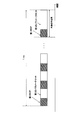
- FIG. 7 shows an arrangement example of demodulation reference signals according to the present embodiment.
- FIG. 7 shows, as an example, the arrangement of demodulation reference signals in 12 subcarriers in the frequency direction and 14 OFDM symbols in the time direction. A region indicated by one subcarrier and one OFDM symbol is also called a resource element.
- the first DMRS is arranged in the resource element hatched by the upper right line and the resource element hatched by the lower right line.
- the second DMRS is arranged in a resource element hatched by a vertical line and a resource element hatched by a horizontal line. Two resource elements hatched by the same line are spread and multiplexed with an orthogonal cover code (OCC).
- OCC orthogonal cover code
- the first DMRS and the second DMRS can be transmitted independently.
- the first DMRS and the second DMRS are transmitted with an OCC sequence length of 2.
- the antenna port number for transmitting the first DMRS and the antenna port number for transmitting the second DMRS are different.
- the OCC sequence length may be changed between the case where the first DMRS or the second DMRS is arranged alone and the case where both the first DMRS and the second DMRS are arranged.
- the OCC sequence length is 2
- the first DMRS arranged in the resource element hatched in the upper right and the second DMRS arranged in the resource element hatched in the vertical line are spread and multiplexed with an OCC sequence length of 4.
- the number of orthogonal DMRSs varies between when the first DMRS or the second DMRS is transmitted alone and when both the first DMRS and the second DMRS are transmitted. Since the number of DMRS resource elements can be flexibly changed in accordance with the number of spatially multiplexed streams (number of layers and ranks), efficient communication can be achieved.
- phase noise of the oscillator may become a problem. Due to the phase noise, the phase of the received signal varies with time. In this case, it is desirable to compensate for phase noise.
- the phase noise includes a common phase error (CPE: Common Phase Error) for all subcarriers.
- CPE Common Phase Error
- a demodulated reference signal having a high frequency density that is arranged on all subcarriers is desirable.
- a demodulated reference signal with a high time density is desirable in order to follow the temporal fluctuation of phase noise. If this is achieved with one demodulation reference signal, many radio resources are consumed, and the efficiency is degraded.
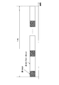
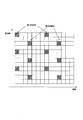
- FIG. 8 is an example of a demodulation reference signal according to this embodiment.
- the first DMRS is arranged in the resource element hatched by the upper right line
- the second DMRS is arranged in the resource element hatched by the lower right line.
- the first DMRS is a demodulation reference signal having a high frequency density
- the second DMRS is a demodulation reference signal having a high time density.
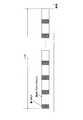
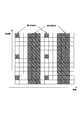
- FIG. 9 is an example of arrangement of demodulation reference signals according to the present embodiment.
- the first DMRS is arranged in the resource element hatched by the upper right line
- the second DMRS is arranged in the resource element hatched by the lower right line.
- the base station apparatus can transmit either the first DMRS or the second DMRS to the terminal apparatus moving at low speed, and can transmit the first DMRS and the second DMRS to the terminal apparatus moving at high speed. For this reason, the base station apparatus can transmit a demodulation reference signal efficiently.
- DMRS is also used for purposes other than demodulation. For example, when communicating using beam forming, the optimum beam changes depending on the movement or rotation of the terminal device, so it is necessary to follow the beam.
- DMRS can be used for beam following.
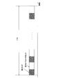
- FIG. 10 is an example of the arrangement of demodulation reference signals according to the present embodiment.
- the first DMRS is arranged in the resource element hatched by the upper right line
- the second DMRS is arranged in the resource element hatched by the lower right line.
- the first DMRS is transmitted for demodulation and the second DMRS is transmitted for beam tracking.
- the base station apparatus / terminal apparatus transmits the second DMRS by beam forming with the same beam pattern (direction) in each OFDM symbol.
- the beam pattern applied to the second DMRS may be the same as or different from the first DMRS and the data signal.
- the terminal device / base station device on the receiving side can demodulate the data signal using the first DMRS and search for a suitable received beam using the second DMRS. It is also possible to calculate CSI using the second DMRS.
- the base station apparatus / terminal apparatus can transmit the second DMRS by performing beamforming with a different beam pattern for each OFDM symbol.
- the base station apparatus / terminal apparatus that has received the second DMRS indicates information indicating the most suitable DMRS (for example, OFDM symbol number / slot number / subframe number / subband including DMRS having the highest received SNR).
- the base station apparatus / terminal apparatus that transmitted the second DMRS is preferably notified by notifying the base station apparatus / terminal apparatus that transmitted the second DMRS) information indicating time / frequency resources such as numbers. Can be identified.
- the information indicating the most suitable DMRS can be included in the CSI calculated by the terminal device based on the second DMRS.
- the base station apparatus / terminal apparatus can perform efficient communication suitable for various wireless environments and transmission methods by transmitting a plurality of types of DMRS.
- the base station apparatus can include the parameters of the first downlink DMRS and / or the second downlink DMRS in the control information and transmit it to the terminal apparatus.
- the parameters of the first downlink DMRS include part or all of the number of layers, antenna port number, arrangement pattern, frequency density, time density, and scrambling identity.
- the arrangement pattern indicates one of arrangement candidates for DMRS resource elements (subcarriers, resource blocks, subbands, OFDM symbols). In the case of periodic arrangement, the arrangement pattern indicates the first resource element (subcarrier, resource block, subband, OFDM symbol).
- the frequency density is a density of DMRS arranged in the frequency domain, and indicates an arrangement on all subcarriers or a part of subcarriers.
- the granularity of the arrangement on some subcarriers is one or more.
- the time density is a density of DMRS arranged in the time domain, and indicates an arrangement in all OFDM symbols or a part of OFDM symbols. There are one or more granularities of arrangement in some OFDM symbols.
- the scrambling identity is a parameter relating to an initial value for generating a DMRS sequence.
- the parameters of the second downlink DMRS include part or all of the number of layers, antenna port number, arrangement pattern, frequency density, time density, and scrambling identity. However, some or all of the parameters of the first DMRS and the parameters of the second DMRS may be different. For example, the number of layers is larger in the second DMRS parameter than in the first DMRS parameter.
- the antenna port number has more parameters for the second DMRS than for the first DMRS.
- the antenna port number is a different number between the first DMRS parameter and the second DMRS parameter.
- the first DMRS and the second DMRS differ in the pattern and number of arrangement patterns that can be set.
- the first DMRS has one arrangement pattern
- the second DMRS has a plurality of arrangement patterns.
- the frequency density / time density can be set more in the parameters of the second DMRS than in the parameters of the first DMRS.
- the first DMRS parameter and the second DMRS parameter include a setting indicating that DMRS is not transmitted. For example, not transmitting DMRS is indicated by an arrangement pattern or time / frequency density.
- the parameter of 1st DMRS or the parameter of 2nd DMRS and the parameter which can be set, a candidate pattern, and the number of candidates may change for every carrier frequency range.
- the base station apparatus notifies the terminal apparatus of information (multiplex notification information) indicating that the data signal addressed to the terminal apparatus is spatially multiplexed with the data signal addressed to the terminal apparatus other than the terminal apparatus. can do. Since the terminal device can recognize that the data signal addressed to the terminal device other than the own device is multiplexed with the data signal addressed to the own device based on the multiplex notification information, the terminal device other than the own device. Interference suppression processing in which the addressed data signal is regarded as an interference signal can be applied to the received signal. Further, the base station apparatus can notify the terminal apparatus of the parameters of the first DMRS and the second DMRS addressed to terminal apparatuses other than the terminal apparatus.
- the base station apparatus spatially multiplexes data signals addressed to a terminal apparatus of 5 or more when predetermined radio parameters (for example, signal waveform, subcarrier spacing, spatial multiplexing number) indicate a predetermined value.
- the first DMRS and / or the second DMRS parameters addressed to the terminal device other than the terminal device can be notified to the terminal device.
- the base station apparatus uses the first DMRS and / or second DMRS parameter notified to the terminal apparatus as the first DMRS and / or second DMRS addressed to the terminal apparatus other than the terminal apparatus.
- the terminal device can be notified including the parameters.
- the first DMRS may be addressed to the own terminal device
- the second DMRS may be addressed to a terminal device other than the terminal device.
- Information indicating that the data signal addressed to the terminal device is spatially multiplexed by the base station device with respect to the data signal addressed to the terminal device Is not limited to anything.
- information instructing the base station apparatus to apply a modulo operation to the received signal to the terminal apparatus can be handled as the multiple notification information. This is because when the base station apparatus spatially multiplexes the data signal using nonlinear precoding, the terminal apparatus needs to perform a modulo operation on the received signal.
- the terminal apparatus may recognize that the data signal addressed to the terminal apparatus other than the own apparatus is spatially multiplexed with respect to the data signal addressed to the terminal apparatus. it can.
- the base station apparatus / terminal apparatus may not transmit the first DMRS and the second DMRS.
- the receiving side terminal device / base station device demodulates the data signal without using DMRS.
- the base station apparatus may always transmit the first DMRS when transmitting the data signal.
- the time / frequency density of the first DMRS is fixed.
- the second DMRS is an optional arrangement.
- the first DMRS has a fixed time / frequency density pattern, it is not necessary to indicate (set) the time / frequency density with the control information. That is, the control information includes the time / frequency density of the second DMRS.
- the arrangement pattern of the first DMRS may change in each carrier frequency range. For example, in the carrier frequency range lower than a predetermined frequency, the first DMRS is discretely arranged in the frequency direction in the slot (resource block). For example, in a carrier frequency range higher than a predetermined frequency, the first DMRS is allocated to all subcarriers in the slot (resource block).
- the base station apparatus can include the parameters of the first uplink DMRS and / or the second uplink DMRS in the control information and transmit it to the terminal apparatus.
- the terminal apparatus transmits the uplink DMRS based on the parameters of the first uplink DMRS and / or the second uplink DMRS transmitted from the base station apparatus.
- the parameters of the first uplink DMRS include part or all of the number of layers, the OCC sequence, the arrangement pattern, the frequency density, the time density, and the scrambling identity.
- the parameters of the second uplink DMRS include part or all of the number of layers, the OCC sequence, the arrangement pattern, the frequency density, the time density, and the scrambling identity.
- the terminal device can transmit the signal waveform by OFDM and DFT-spread-OFDM (SC-FDMA).
- the terminal apparatus can transmit a plurality of layers (streams) in OFDM, and can transmit one layer (stream) in DFT-spread-OFDM.
- uplink DMRS parameters and settings differ between OFDM and DFT-spread-OFDM.
- the second uplink DMRS is not set (not transmitted).
- the frequency density may be allocated only to all subcarriers.
- the first uplink DMRS parameter and / or the second uplink DMRS parameter includes information indicating transmission power.
- the information indicating the transmission power is a transmission power value of the first uplink DMRS and / or the second uplink DMRS, or a power ratio (power offset) between the first uplink DMRS and the second uplink DMRS. be able to.
- the transmission power of the first uplink DMRS and / or the second uplink DMRS may be set regardless of the signal waveform, or may be set for each signal waveform.
- FIG. 11 is a schematic block diagram showing the configuration of the base station apparatus 1A in the present embodiment.
- the base station apparatus 1 ⁇ / b> A performs transmission / reception with an upper layer processing unit (upper layer processing step) 101, a control unit (control step) 102, a transmission unit (transmission step) 103, and a reception unit (reception step) 104.
- An antenna 105 is included.
- the upper layer processing unit 101 includes a radio resource control unit (radio resource control step) 1011 and a scheduling unit (scheduling step) 1012.
- the transmission unit 103 includes an encoding unit (encoding step) 1031, a modulation unit (modulation step) 1032, a downlink reference signal generation unit (downlink reference signal generation step) 1033, a multiplexing unit (multiplexing step) 1034, a radio A transmission unit (wireless transmission step) 1035 is included.
- the reception unit 104 includes a wireless reception unit (wireless reception step) 1041, a demultiplexing unit (demultiplexing step) 1042, a demodulation unit (demodulation step) 1043, and a decoding unit (decoding step) 1044.
- the upper layer processing unit 101 includes a medium access control (Medium Access Control: MAC) layer, a packet data integration protocol (Packet Data Convergence Protocol: PDCP) layer, a radio link control (Radio Link Control: RLC) layer, a radio resource control (Radio) Resource (Control: RRC) layer processing.
- MAC Medium Access Control
- PDCP Packet Data Convergence Protocol
- RLC Radio Link Control
- RRC radio resource control
- upper layer processing section 101 generates information necessary for controlling transmission section 103 and reception section 104 and outputs the information to control section 102.
- the upper layer processing unit 101 receives information related to the terminal device such as the function (UE capability) of the terminal device from the terminal device. In other words, the terminal apparatus transmits its own function to the base station apparatus using an upper layer signal.
- information on a terminal device includes information indicating whether the terminal device supports a predetermined function, or information indicating that the terminal device has introduced a predetermined function and has completed a test.
- whether or not to support a predetermined function includes whether or not installation and testing for the predetermined function have been completed.
- the terminal device transmits information (parameters) indicating whether the predetermined function is supported.
- the terminal device does not transmit information (parameter) indicating whether or not the predetermined device is supported. That is, whether or not to support the predetermined function is notified by whether or not information (parameter) indicating whether or not to support the predetermined function is transmitted.
- Information (parameter) indicating whether or not a predetermined function is supported may be notified using 1 or 1 bit.
- the radio resource control unit 1011 generates or acquires downlink data (transport block), system information, RRC message, MAC CE, and the like arranged on the downlink PDSCH from the upper node.
- the radio resource control unit 1011 outputs downlink data to the transmission unit 103 and outputs other information to the control unit 102.
- the radio resource control unit 1011 manages various setting information of the terminal device. Also, the radio resource control unit 1011 sets (manages) downlink reference parameters (subcarrier interval), CP length, number of FFT points, and the like. Also, the radio resource control unit 1011 sets (manages) reference parameters (subcarrier interval), CP length, number of FFT points, and the like of the terminal device (uplink).
- Scheduling section 1012 determines the frequency and subframe to which physical channels (PDSCH and PUSCH) are allocated, the coding rate and modulation scheme (or MCS) and transmission power of physical channels (PDSCH and PUSCH), and the like.
- the scheduling unit 1012 outputs the determined information to the control unit 102.
- the scheduling unit 1012 generates information used for scheduling physical channels (PDSCH and PUSCH) based on the scheduling result.
- the scheduling unit 1012 outputs the generated information to the control unit 102.
- the control unit 102 generates a control signal for controlling the transmission unit 103 and the reception unit 104 based on the information input from the higher layer processing unit 101.
- the control unit 102 generates downlink control information based on the information input from the higher layer processing unit 101 and outputs the downlink control information to the transmission unit 103.
- the transmission unit 103 generates a downlink reference signal according to the control signal input from the control unit 102, and encodes the HARQ indicator, downlink control information, and downlink data input from the higher layer processing unit 101. Then, PHICH, PDCCH, EPDCCH, PDSCH, and downlink reference signal are multiplexed, and the signal is transmitted to the terminal apparatus 2 via the transmission / reception antenna 105.
- the encoding unit 1031 uses a predetermined encoding method such as block encoding, convolutional encoding, and turbo encoding for the HARQ indicator, downlink control information, and downlink data input from the higher layer processing unit 101. Encoding is performed using the encoding method determined by the radio resource control unit 1011.
- the modulation unit 1032 converts the coded bits input from the coding unit 1031 to BPSK (Binary Phase Shift Shift Keying), QPSK (quadrature Phase Shift Shift Keying), 16QAM (quadratureamplitude modulation), 64QAM, 256QAM, or the like, or Modulation is performed by the modulation scheme determined by the radio resource control unit 1011.
- the downlink reference signal generation unit 1033 refers to a known sequence that the terminal device 2A obtains according to a predetermined rule based on a physical cell identifier (PCI, cell ID) for identifying the base station device 1A. Generate as a signal.
- PCI physical cell identifier
- the multiplexing unit 1034 multiplexes the modulated modulation symbol of each channel, the generated downlink reference signal, and downlink control information. That is, multiplexing section 1034 arranges the modulated modulation symbol of each channel, the generated downlink reference signal, and downlink control information in the resource element.
- the radio transmission unit 1035 generates an OFDM symbol by performing inverse fast Fourier transform (Inverse Fourier Transform: IFFT) on the multiplexed modulation symbol and the like, and adds a cyclic prefix (cyclic prefix: CP) to the OFDM symbol.
- IFFT inverse fast Fourier transform
- CP cyclic prefix
- the receiving unit 104 separates, demodulates, and decodes the received signal received from the terminal device 2A via the transmission / reception antenna 105 in accordance with the control signal input from the control unit 102, and outputs the decoded information to the upper layer processing unit 101. .
- the radio reception unit 1041 converts an uplink signal received via the transmission / reception antenna 105 into a baseband signal by down-conversion, removes unnecessary frequency components, and amplifies the signal level so that the signal level is properly maintained.
- the level is controlled, quadrature demodulation is performed based on the in-phase component and the quadrature component of the received signal, and the analog signal that has been demodulated is converted into a digital signal.
- the wireless reception unit 1041 removes a portion corresponding to the CP from the converted digital signal.
- Radio receiving section 1041 performs fast Fourier transform (FFT) on the signal from which CP is removed, extracts a signal in the frequency domain, and outputs the signal to demultiplexing section 1042.
- FFT fast Fourier transform
- the demultiplexing unit 1042 demultiplexes the signal input from the wireless reception unit 1041 into signals such as PUCCH, PUSCH, and uplink reference signal. This separation is performed based on radio resource allocation information included in the uplink grant that is determined in advance by the radio resource control unit 1011 by the base station apparatus 1A and notified to each terminal apparatus 2.
- the demultiplexing unit 1042 compensates for the propagation paths of the PUCCH and PUSCH. Further, the demultiplexing unit 1042 demultiplexes the uplink reference signal.
- the demodulator 1043 performs inverse discrete Fourier transform (Inverse Discrete Fourier Transform: IDFT) on the PUSCH to obtain modulation symbols, and for each of the PUCCH and PUSCH modulation symbols, BPSK, QPSK, 16QAM, 64QAM, 256QAM, etc.
- IDFT inverse discrete Fourier transform
- the received signal is demodulated by using a modulation method determined or notified in advance by the own device to each of the terminal devices 2 using an uplink grant.
- the decoding unit 1044 uses the coding rate of the demodulated PUCCH and PUSCH at a coding rate that is determined in advance according to a predetermined encoding method or that the device itself has previously notified the terminal device 2 using an uplink grant. Decoding is performed, and the decoded uplink data and uplink control information are output to the upper layer processing section 101. When PUSCH is retransmitted, decoding section 1044 performs decoding using the coded bits held in the HARQ buffer input from higher layer processing section 101 and the demodulated coded bits.
- FIG. 12 is a schematic block diagram showing the configuration of the terminal device 2 in the present embodiment.
- the terminal device 2A includes an upper layer processing unit (upper layer processing step) 201, a control unit (control step) 202, a transmission unit (transmission step) 203, a reception unit (reception step) 204, a channel state An information generation unit (channel state information generation step) 205 and a transmission / reception antenna 206 are included.
- the upper layer processing unit 201 includes a radio resource control unit (radio resource control step) 2011 and a scheduling information interpretation unit (scheduling information interpretation step) 2012.
- the transmission unit 203 includes an encoding unit (encoding step) 2031, a modulation unit (modulation step) 2032, an uplink reference signal generation unit (uplink reference signal generation step) 2033, a multiplexing unit (multiplexing step) 2034, and a radio A transmission unit (wireless transmission step) 2035 is included.
- the reception unit 204 includes a wireless reception unit (wireless reception step) 2041, a demultiplexing unit (demultiplexing step) 2042, and a signal detection unit (signal detection step) 2043.
- the upper layer processing unit 201 outputs uplink data (transport block) generated by a user operation or the like to the transmission unit 203. Further, the upper layer processing unit 201 includes a medium access control (Medium Access Control: MAC) layer, a packet data integration protocol (Packet Data Convergence Protocol: PDCP) layer, a radio link control (Radio Link Control: RLC) layer, and a radio resource control. Process the (Radio Resource Control: RRC) layer.
- Medium Access Control Medium Access Control: MAC
- PDCP Packet Data Convergence Protocol
- RLC Radio Link Control
- RRC Radio Resource Control
- the upper layer processing unit 201 outputs information indicating the function of the terminal device supported by the own terminal device to the transmission unit 203.
- the radio resource control unit 2011 manages various setting information of the own terminal device. Also, the radio resource control unit 2011 generates information arranged in each uplink channel and outputs the information to the transmission unit 203.
- the radio resource control unit 2011 acquires setting information regarding CSI feedback transmitted from the base station apparatus, and outputs the setting information to the control unit 202. Also, the radio resource control unit 1011 obtains setting information such as a downlink reference parameter (subcarrier interval), CP length, and number of FFT points from the base station apparatus, and outputs the setting information to the control unit 202. Also, the radio resource control unit 1011 acquires setting information such as uplink reference parameters (subcarrier interval), CP length, number of FFT points, and the like from the base station apparatus, and outputs them to the control unit 202.
- the scheduling information interpretation unit 2012 interprets the downlink control information received via the reception unit 204 and determines scheduling information.
- the scheduling information interpretation unit 2012 generates control information for controlling the reception unit 204 and the transmission unit 203 based on the scheduling information, and outputs the control information to the control unit 202.
- the control unit 202 generates a control signal for controlling the receiving unit 204, the channel state information generating unit 205, and the transmitting unit 203 based on the information input from the higher layer processing unit 201.
- the control unit 202 controls the reception unit 204 and the transmission unit 203 by outputting the generated control signal to the reception unit 204, the channel state information generation unit 205, and the transmission unit 203.
- the control unit 202 controls the transmission unit 203 to transmit the CSI generated by the channel state information generation unit 205 to the base station apparatus.
- the receiving unit 204 separates, demodulates, and decodes the received signal received from the base station apparatus 1A via the transmission / reception antenna 206 according to the control signal input from the control unit 202, and sends the decoded information to the upper layer processing unit 201. Output.
- the radio reception unit 2041 converts a downlink signal received via the transmission / reception antenna 206 into a baseband signal by down-conversion, removes unnecessary frequency components, and increases the amplification level so that the signal level is appropriately maintained. , And quadrature demodulation based on the in-phase and quadrature components of the received signal, and converting the quadrature demodulated analog signal into a digital signal.
- the wireless reception unit 2041 removes a portion corresponding to CP from the converted digital signal, performs fast Fourier transform on the signal from which CP is removed, and extracts a frequency domain signal.
- the demultiplexing unit 2042 separates the extracted signal into PHICH, PDCCH, EPDCCH, PDSCH, and downlink reference signal. Further, the demultiplexing unit 2042 compensates for the PHICH, PDCCH, and EPDCCH channels based on the channel estimation value of the desired signal obtained from the channel measurement, detects downlink control information, and sends it to the control unit 202. Output. In addition, control unit 202 outputs PDSCH and the channel estimation value of the desired signal to signal detection unit 2043.
- the signal detection unit 2043 detects a signal using the PDSCH and the channel estimation value, and outputs the signal to the higher layer processing unit 201.
- the transmission unit 203 generates an uplink reference signal according to the control signal input from the control unit 202, encodes and modulates the uplink data (transport block) input from the higher layer processing unit 201, PUCCH, The PUSCH and the generated uplink reference signal are multiplexed and transmitted to the base station apparatus 1A via the transmission / reception antenna 206.
- the encoding unit 2031 performs encoding such as convolutional encoding and block encoding on the uplink control information input from the higher layer processing unit 201. Also, the coding unit 2031 performs turbo coding based on information used for PUSCH scheduling.
- the modulation unit 2032 modulates the coded bits input from the coding unit 2031 using a modulation scheme notified by downlink control information such as BPSK, QPSK, 16QAM, 64QAM, or a modulation scheme predetermined for each channel. .
- the uplink reference signal generation unit 2033 has a physical cell identifier (physical cell identity: referred to as PCI, Cell ID, etc.) for identifying the base station apparatus 1A, a bandwidth for arranging an uplink reference signal, and an uplink grant.
- a sequence determined by a predetermined rule is generated on the basis of the cyclic shift and the parameter value for generating the DMRS sequence notified in (1).
- the multiplexing unit 2034 rearranges the PUSCH modulation symbols in parallel according to the control signal input from the control unit 202, and then performs a discrete Fourier transform (DFT). Also, the multiplexing unit 2034 multiplexes the PUCCH and PUSCH signals and the generated uplink reference signal for each transmission antenna port. That is, multiplexing section 2034 arranges the PUCCH and PUSCH signals and the generated uplink reference signal in the resource element for each transmission antenna port.
- DFT discrete Fourier transform
- the wireless transmission unit 2035 performs inverse fast Fourier transform (Inverse Fast Fourier Transform: IFFT) on the multiplexed signal, performs SC-FDMA modulation, generates an SC-FDMA symbol, and generates the generated SC-FDMA symbol.
- IFFT inverse Fast Fourier Transform
- CP is added to generate a baseband digital signal (SC-FDMA signal), convert the baseband digital signal to an analog signal, remove excess frequency components, convert to a carrier frequency by up-conversion,
- the power is amplified and output to the transmission / reception antenna 206 for transmission.
- terminal apparatus 2 is not limited to the SC-FDMA system, and can perform OFDMA system modulation.
- the control unit 202 of the terminal device 2 has a function of controlling the transmission power of the uplink signal to the base station device 1 generated by the transmission unit 203.
- the control unit 202 can calculate the transmission power P PUSCH, c (i) related to the transmission of the i-th subframe transmitted to the c-th cell based on the equation (1).
- P CMAX, c (i) is a term relating to the maximum allowable transmission power of the terminal apparatus 2 related to transmission of the i-th subframe transmitted to the c-th cell.
- M PUSCH, c (i) represents the number of resource blocks allocated to the terminal device 2 in transmission of the i-th subframe transmitted to the c-th cell. That is, the term represented by 10 log 10 (M PUSCH, c (i)) is a term relating to the radio resource amount allocated to the terminal device 2.
- P O_PUSCH, c (j) is a term relating to the target received power when transmitting to the c-th cell, and the target received power when the terminal apparatus 2 transmits an uplink signal to the base station apparatus 1 including the c-th cell.
- ⁇ c (j) is a term (coefficient) related to compensation for propagation loss between the base station apparatus 1 and the terminal apparatus 2 including the c-th cell.
- j is an integer
- ⁇ c (j) can be set to different values by changing j.
- PL c is a term relating to a propagation loss between the base station apparatus 1 and the terminal apparatus 2 including the c-th cell.
- ⁇ TF, c (i) is a term relating to a modulation scheme applied by the modulation unit 2032 to a signal included in the i-th subframe transmitted to the c-th cell.
- f c (i) is a term relating to a control error generated when the control unit 202 controls transmission power of a signal included in the i-th subframe transmitted to the c-th cell.
- the variable name of each term in the formula (1) is set for convenience of explanation, and the operation of the terminal device 2 according to the present embodiment is not limited by the variable name. Can be any name.
- the control unit 202 of the terminal device 2 includes a frame configuration (or a radio parameter that defines the frame configuration or a base parameter or parameter that determines a radio frame parameter) set by the multiplexing unit 2034 (transmission unit 203).
- the transmission power can be controlled based on a set, a reference parameter, or a reference parameter set.
- at least one of the plurality of terms included in Expression (1) is associated with the frame configuration set by the multiplexing unit 2034.
- the control unit 202 can control the transmission power using one subframe length as a control unit as shown in Equation (1).
- the control unit 202 can also control transmission power in an arbitrary control unit such as a slot length, an OFDM symbol length, an SC-FDMA symbol length, and a frame length instead of the subframe length.
- the control unit 202 according to the present embodiment can set a unit for controlling transmission power based on the frame configuration set by the multiplexing unit 2034. For example, for the 100th frame configuration with a wide subcarrier interval, the time interval (time granularity) at which the control unit 202 controls the transmission power is larger than the 200th frame configuration with a subcarrier interval narrower than the 100th frame configuration. Can also be narrowed.
- control unit 202 can more flexibly control the transmission power of a signal having a frame configuration with a short frame length (symbol length).
- control unit 202 according to the present embodiment can change the time unit for calculating a plurality of terms included in Equation (1) for each frame configuration.
- the control unit 202 can set a term relating to the maximum allowable transmission power in Expression (1) for each frame configuration.
- the control unit 202 can set the maximum allowable transmission power in a frame configuration requiring high reliability higher than that in other frame configurations.
- an uplink signal transmitted to the base station apparatus 1 with a frame configuration having a high maximum allowable transmission power can be received with better reception quality than a signal transmitted with another frame configuration. It can be received by the base station apparatus 1.
- high reliability for example, in the case of a predetermined frame configuration
- the terminal device 2 always transmits with the maximum allowable transmission power without performing transmission power control according to an instruction or setting from the base station device 1. can do.
- the control unit 202 according to the present embodiment can set a term related to the amount of radio resources allocated to the terminal device 2 in Expression (1) for each frame configuration.
- the control unit 202 according to the present embodiment can set a term related to the radio resource amount using a common unit regardless of the frame configuration.
- the control unit 202 according to the present embodiment can set a term related to the radio resource amount in a unit of RB-2 with a fixed frequency bandwidth per unit. Since the bandwidth per unit of RB-2 is uniquely fixed, the number of subcarriers included in RB-2 is different when the subcarrier interval is different among the parameters included in the frame configuration.
- the control unit 202 can set a term related to the radio resource amount regardless of the frame configuration.
- the control unit 202 can set a term relating to the target received power in Expression (1) for each frame configuration. For example, the control unit 202 sets the target reception power set in the case of a predetermined frame configuration to be higher or lower than the target reception power set in the case of a frame configuration other than the predetermined frame configuration. be able to. By setting the target reception power set to a predetermined frame configuration high by the control unit 202, it is possible to improve the reception quality of a signal having the predetermined frame configuration. On the other hand, when the control unit 202 sets the target received power set to a predetermined frame configuration to be low, the interference power that a signal having the predetermined frame configuration exerts on other cells and adjacent channels can be reduced.
- the control unit 202 can further add a term related to the gain obtained by beam forming performed by the base station device 1 and the terminal device 2 to the term related to the target received power in the equation (1).
- the control unit 202 can define B c (i) as a compensation coefficient related to the beamforming gain, and set B c (i) ⁇ P O_PUSCH, c (j) as a term related to the target received power.
- the control unit 202 can consider a compensation coefficient related to the beamforming gain when a predetermined frame configuration is set.
- the control unit 202 can determine a compensation coefficient related to the beamforming gain based on whether or not the antenna 206 of the terminal device 2 or the antenna 105 of the base station device 1 performs beamforming. For example, the control unit 202 sets B c (i) to 1 when beam forming is not performed, and sets B c (i) to a real number that is 1 or less and greater than 0 when beam forming is performed. can do.
- the control unit 202 can set a term concerning propagation loss compensation in the equation (1) for each frame configuration.
- the control unit 202 can set a value included in a set of values that can be set in the term relating to propagation loss compensation for each frame configuration.
- the control unit 202 can set the term concerning the propagation loss in the equation (1) for each frame configuration. For example, when a predetermined frame configuration is set, the control unit 202 can consider the compensation coefficient related to the beamforming gain in the term related to the propagation loss. For example, when the control unit 202 is set to a predetermined frame configuration, when setting the propagation loss, the control unit 202 takes into account the gain due to beamforming performed by the base station device 1 and the terminal device 2 and sets the propagation loss. Can be measured.
- the control part 202 can add the term regarding beam forming further to Formula (1).
- the control unit 202 can set a gain obtained by beam forming performed by the base station apparatus 1 and the terminal apparatus 2.
- the control unit 202 can set a value selected from a plurality of values in the term relating to the beam forming.
- the control unit 202 can set a predetermined value (for example, 0) in a term related to the beam forming.
- the control unit 202 can set a difference between the gain obtained by beam forming performed by the base station apparatus 1 and the terminal apparatus 2 and the gain by reference beam forming.
- the control unit 202 can use, for example, information related to a reception gain of a signal including common reference signals or common control information transmitted from the base station apparatus 1.
- the control unit 202 can use information related to a gain obtained by beamforming as information related to a reception gain of a signal including a unique reference signal or data addressed to the terminal device 2.
- control unit 202 controls the transmission power of an uplink signal having a predetermined frame configuration based on the equation (1)
- a plurality of terms included in the equation (1) are set for the predetermined frame configuration.
- the calculated value can be used for calculation.
- the control unit 202 can also set any one or a plurality of terms in Formula (1) to a common value regardless of the set frame configuration. For example, as the propagation loss, a propagation loss calculated in one frame configuration can be used as a propagation loss in another frame configuration.
- the terminal device 2 uses a plurality of component carriers simultaneously (by carrier aggregation).
- the control unit 202 can calculate transmission power for each component carrier and control the transmission power based on the total value.
- the control unit 202 can add the weights for each component carrier instead of simply adding them.
- the control unit 202 can determine a weighting coefficient to be performed for each component carrier based on the frame configuration set for the component carrier. It goes without saying that the control unit 202 according to the present embodiment can also control transmission power when carrier aggregation is performed on a plurality of component carriers having different frame configurations.
- the terminal device 2 further uses at least one of a data signal and a control signal as an uplink signal.
- the control unit 202 can subtract the transmission power required for transmission of the control signal from the term relating to the maximum allowable transmission power in Equation (1). By controlling in this way, the terminal device 2 can avoid the problem that the control signal cannot be transmitted.
- the transmission power required for transmission of the control signal to be subtracted from the term relating to the maximum allowable transmission power in Expression (1) by the control unit 202 according to the present embodiment is a frame configuration set to a signal including the control signal Can be set based on.
- the receiving unit 204 (upper layer processing unit 201) of the terminal device 2 can acquire control information related to at least one of a plurality of terms included in the expression (1) from the base station device 1.
- the terminal device 2 obtains the control information from broadcast information of the base station device 1 (for example, information contained in a MIB (Master Information Block) or SIB (System Information Block) broadcasted via BCH (Broadcast Channel)). can do.
- the terminal apparatus 2 can obtain the control information from physical layer control information (for example, DCI notified via the PDCCH) transmitted by the base station apparatus 1.
- the cycle in which the terminal device 2 acquires the control information from the base station device 1 may be different for each set frame configuration.
- the control information related to at least one of the plurality of terms included in the expression (1) acquired by the terminal device 2 can be associated with a predetermined frame configuration among the plurality of frame configurations. Based on the acquired control information associated with the predetermined frame configuration, the control unit 202 associates with at least one of a plurality of terms included in Equation (1) associated with a frame configuration other than the predetermined frame configuration. A term can be set.
- the base station apparatus 1 can notify the terminal apparatus 2 of control information related to at least one of a plurality of terms included in the expression (1) used when the terminal apparatus 2 controls transmission power.
- the control information notified by the base station device 1 to the terminal device 2 and the notification method can be determined based on the frame configuration set by the base station device 1.
- the base station device 1 includes the control information associated with a predetermined frame configuration in broadcast information (for example, MIB (Master Information Block) or SIB (System Information Block) broadcasted via BCH (Broadcast Channel) Information).
- the base station apparatus 1 can transmit the control information associated with a predetermined frame configuration by including it in physical layer control information (for example, a signal including a DCI or TPC command notified via the PDCCH).
- the period at which the base station apparatus 1 broadcasts or transmits a signal including the control information may be different for each set frame configuration.
- the base station apparatus 1 can be set so that the control information associated with different frame configurations should not be transmitted at the same time. Further, the base station apparatus 1 can be set so that the control information associated with a predetermined frame configuration can be notified to the terminal apparatus 2 only with a signal having the predetermined frame configuration.
- the control unit 202 can set the transmission power per subcarrier to a different value for each frame configuration when controlling the transmission power. For example, the transmission power per subcarrier in a frame configuration with a subcarrier interval of 15 kHz can be set to 1 ⁇ 2 of the transmission power per subcarrier in a frame configuration with a subcarrier interval of 30 kHz.
- the control unit 202 controls the transmission power, so that the transmission power per unit frequency of the uplink signal transmitted by the terminal device 2 (for example, transmission power per 1 MHz or transmission power spectral density) regardless of the frame configuration. ) Can be made constant.
- the flatness flatness, smoothness
- the terminal apparatus 2 can notify the base station apparatus 1 of information regarding the transmission power setting capability of the own apparatus.
- the information regarding the setting capability may be a power headroom (PH).
- the control unit 202 of the terminal device 2 according to the present embodiment calculates the power headroom PH type1, c (i) related to the transmission of the i-th subframe transmitted to the c-th cell based on, for example, Expression (2). be able to.
- PH is expressed as a difference between the maximum allowable transmission power of the terminal device 2 and the transmission power requested by the terminal device 2 from the base station device 1. If PH is a positive value, this indicates that the terminal device 2 still has a sufficient transmission power (the terminal device 2 can transmit a signal with a transmission power higher than the current transmission power). If PH is 0, it indicates that the terminal device 2 has no remaining transmission power (the terminal device 2 cannot transmit a signal with a higher transmission power). If PH is a negative value, it indicates that the terminal device 2 cannot transmit a signal with the transmission power required for the base station device 1. When the terminal device 2 notifies the base station device 1 of the PH, the base station device 1 can grasp the radio resource amount to be allocated to the terminal device 2.
- the terminal apparatus 2 when the terminal apparatus 2 reports the PH to the base station apparatus 1 when resources are not allocated, the terminal apparatus 2 can calculate the PH without considering the radio resource amount. Further, when resources are allocated but transmission is not possible for some reason, the terminal device 2 can calculate PH in consideration of the allocated resources.
- the terminal apparatus 2 can notify the base station apparatus 1 of the PH for each frame configuration.
- the cycle in which the terminal device 2 notifies the base station device 1 of the PH may be different for each frame configuration.
- the terminal device 2 can notify the base station device 1 only of the PH related to the frame configuration requested from the base station device 1.
- the base station device 1 and the terminal device 2 can negotiate a predetermined frame configuration for calculating PH in advance.
- the base station device 1 can calculate the PH associated with a frame configuration other than the predetermined frame configuration from the PH associated with the predetermined frame configuration notified from the terminal device 2.
- the terms subtracted from the maximum allowable transmission power include all of the plurality of terms included in Equation (1) used when the control unit 202 calculates transmission power. Yes.
- the control unit 202 does not necessarily include all of the plurality of terms included in Expression (1) in the term subtracted from the maximum allowable transmission power.
- the term included in the term subtracted from the maximum allowable transmission power by the control unit 202 may be a different combination for each set frame configuration, or may be common among the frame configurations.
- the terminal apparatus 2 according to the present embodiment can always transmit an uplink signal with the maximum allowable transmission power of the terminal apparatus 2 in a predetermined frame configuration.
- the terminal device 2 does not have to notify the base station device 1 of the PH because the PH is always 0. That is, the terminal device 2 according to the present embodiment can be set not to transmit PH by setting a predetermined frame configuration.
- a program that operates on an apparatus according to one aspect of the present invention is a program that controls a central processing unit (CPU) or the like to function a computer so as to realize the function of the embodiment according to one aspect of the present invention. Also good.
- the program or information handled by the program is temporarily stored in a volatile memory such as a Random Access Memory (RAM), a non-volatile memory such as a flash memory, a Hard Disk Drive (HDD), or other storage system.
- RAM Random Access Memory
- HDD Hard Disk Drive
- a program for realizing the functions of the embodiments according to one aspect of the present invention may be recorded on a computer-readable recording medium. You may implement
- the “computer system” here is a computer system built in the apparatus, and includes hardware such as an operating system and peripheral devices.
- the “computer-readable recording medium” refers to a semiconductor recording medium, an optical recording medium, a magnetic recording medium, a medium that dynamically holds a program for a short time, or other recording medium that can be read by a computer. Also good.
- each functional block or various features of the apparatus used in the above-described embodiments can be implemented or executed by an electric circuit, for example, an integrated circuit or a plurality of integrated circuits.
- Electrical circuits designed to perform the functions described herein can be general purpose processors, digital signal processors (DSPs), application specific integrated circuits (ASICs), field programmable gate arrays (FPGAs), or others Programmable logic devices, discrete gate or transistor logic, discrete hardware components, or a combination thereof.
- a general purpose processor may be a microprocessor or a conventional processor, controller, microcontroller, or state machine.
- the electric circuit described above may be configured by a digital circuit or an analog circuit.
- one or more aspects of the present invention can use a new integrated circuit based on the technology.
- the present invention is not limited to the above-described embodiment.
- an example of an apparatus has been described.
- the present invention is not limited to this, and a stationary or non-movable electronic device installed indoors or outdoors, such as an AV device, a kitchen device, It can be applied to terminal devices or communication devices such as cleaning / washing equipment, air conditioning equipment, office equipment, vending machines, and other daily life equipment.
- One embodiment of the present invention is suitable for use in a base station device, a terminal device, and a communication method.
- One embodiment of the present invention is used in, for example, a communication system, a communication device (for example, a mobile phone device, a base station device, a wireless LAN device, or a sensor device), an integrated circuit (for example, a communication chip), a program, or the like. be able to.
- Base station apparatus 2A, 2B Terminal apparatus 101 Upper layer processing section 102 Control section 103 Transmission section 104 Reception section 105 Transmission / reception antenna 1011 Radio resource control section 1012 Scheduling section 1031 Encoding section 1032 Modulation section 1033 Downlink reference signal generation section 1034 Multiplexing Unit 1035 radio transmission unit 1041 radio reception unit 1042 demultiplexing unit 1043 demodulation unit 1044 decoding unit 201 upper layer processing unit 202 control unit 203 transmission unit 204 reception unit 205 channel state information generation unit 206 transmission / reception antenna 2011 radio resource control unit 2012 scheduling information Interpreter 2031 Encoder 2032 Modulator 2033 Uplink reference signal generator 2034 Multiplexer 2035 Radio transmitter 2041 Radio receiver 2042 Demultiplexer 2043 Signal detector
Landscapes
- Engineering & Computer Science (AREA)
- Signal Processing (AREA)
- Computer Networks & Wireless Communication (AREA)
- Mobile Radio Communication Systems (AREA)
Abstract
データ信号の復調に用いられる参照信号である第1の復調参照信号及び第2の復調参照信号を生成する下りリンク参照信号生成部と、前記第1の復調参照信号、前記第2の復調参照信号、及び制御情報を前記端末装置に送信する無線送信部と、を備え、前記制御情報は、前記第1の復調参照信号に関するパラメータ及び前記第2の復調参照信号に関するパラメータを含み、前記第1の復調参照信号に関するパラメータはアンテナポート番号を含み、前記第2の復調参照信号に関するパラメータは、アンテナポート番号、及び、復調参照信号をスロットに配置する時間領域の密度又は周波数領域の密度を含み、前記第1の復調参照信号は、前記第2の復調参照信号よりもスロット内で前方に配置される。
Description
本発明は、基地局装置、端末装置および通信方法に関する。
本願は、2016年11月2日に日本に出願された特願2016-214930号について優先権を主張し、その内容をここに援用する。
本願は、2016年11月2日に日本に出願された特願2016-214930号について優先権を主張し、その内容をここに援用する。
3GPP(Third Generation Partnership Project)によって仕様策定されたLTE(Long Term Evolution)、LTE-A(LTE-Advanced)のような通信システムでは、基地局装置(基地局、送信局、送信点、下りリンク送信装置、上りリンク受信装置、送信アンテナ群、送信アンテナポート群、コンポーネントキャリア、eNodeB、アクセスポイント、AP)或いは基地局装置に準じる送信局がカバーするエリアをセル(Cell)状に複数配置するセルラ構成とすることにより、通信エリアを拡大することができる。基地局装置には、端末装置(受信局、受信点、下りリンク受信装置、上りリンク送信装置、受信アンテナ群、受信アンテナポート群、UE、ステーション、STA)が接続する。このセルラ構成において、隣接するセルまたはセクタ間で同一周波数を利用することで、周波数利用効率を向上させることができる。
また、2020年頃の商業サービス開始を目指し、第5世代移動無線通信システム(5Gシステム)に関する研究・開発活動が盛んに行なわれている。最近、国際標準化機関である国際電気通信連合 無線通信部門(International Telecommunication Union Radio communications Sector:ITU-R)より、5Gシステムの標準方式(International mobile telecommunication - 2020 and beyond:IMT-2020)に関するビジョン勧告が報告された(非特許文献1参照)。
5Gシステムでは、3つの大きなユースシナリオ(Enhanced mobile broadband(EMBB)、Enhanced Massive machine type communication(eMTC)、Ultra-reliable and low latency communication(URLLC))に代表される様々な要求条件を満たすために、様々な周波数バンドを組み合わせて、無線アクセスネットワークを運用することが想定されている。そのため、5Gシステムでは、従来のLTE/LTE-Aとは異なり、同じアクセス方式でありながら、異なる無線パラメータ(サブキャリア間隔など)を有するフレームフォーマットを多重して用いることが想定されている。
"IMT Vision - Framework and overall objectives of the future development of IMT for 2020 and beyond," Recommendation ITU-R M.2083-0, Sept.2015.
しかしながら、複数のフレームフォーマットには、それぞれ適した通信方式、通信方法があることが想定される。5Gシステムは、各フレームフォーマットに適した通信を維持したまま、これらを統合するシステムである必要がある。
本発明の一態様はこのような事情を鑑みてなされたものであり、その目的は、複数のフレームフォーマットが使用されるシステムにおいて、スループット、通信効率などの通信性能を改善することが可能な基地局装置、端末装置及び通信方法を提供することにある。
上述した課題を解決するために本発明の一態様に係る基地局装置、端末装置および通信方法の構成は、次の通りである。
本発明の一態様に係る基地局装置は、端末装置と通信する基地局装置であって、データ信号の復調に用いられる参照信号である第1の復調参照信号及び第2の復調参照信号を生成する下りリンク参照信号生成部と、前記第1の復調参照信号、前記第2の復調参照信号、及び制御情報を前記端末装置に送信する無線送信部と、を備え、前記制御情報は、前記第1の復調参照信号に関するパラメータ及び前記第2の復調参照信号に関するパラメータを含み、前記第1の復調参照信号に関するパラメータはアンテナポート番号を含み、前記第2の復調参照信号に関するパラメータは、アンテナポート番号、及び、復調参照信号をスロットに配置する時間領域の密度又は周波数領域の密度を含み、前記第1の復調参照信号は、前記第2の復調参照信号よりもスロット内で前方に配置される。
また本発明の一態様に係る基地局装置において、前記第1の復調参照信号は、前記第2の復調参照信号よりもサポート可能な空間多重数が小さい。
また本発明の一態様に係る基地局装置において、前記第1の復調参照信号は、キャリア周波数範囲毎に固定の配置パターンで配置される。
また本発明の一態様に係る基地局装置において、前記キャリア周波数範囲のうちの1つにおいて、前記第1の復調参照信号は、スロットの全サブキャリアに配置される。
また本発明の一態様に係る基地局装置において、前記第1の復調参照信号は、前記第2の復調参照信号よりも周波数領域の密度が大きく、時間領域の密度が小さい。
また本発明の一態様における端末装置は、基地局装置と通信する端末装置であって、データ信号の復調に用いられる参照信号である第1の復調参照信号、第2の復調参照信号、データ信号及び制御情報を前記基地局装置から受信する無線受信部と、前記第1の復調参照信号及び第2の復調参照信号を用いてデータ信号を復調する信号検出部と、を備え、前記制御情報は、前記第1の復調参照信号に関するパラメータ及び前記第2の復調参照信号に関するパラメータを含み、前記第1の復調参照信号に関するパラメータはアンテナポート番号を含み、前記第2の復調参照信号に関するパラメータは、アンテナポート番号、及び、復調参照信号をスロットに配置する時間領域の密度又は周波数領域の密度を含み、前記第1の復調参照信号は、前記第2の復調参照信号よりもスロット内で前方に配置される
また本発明の一態様における端末装置において、前記第1の復調参照信号は、前記第2の復調参照信号よりもサポート可能な空間多重数が小さい。
また本発明の一態様における端末装置において、前記第1の復調参照信号は、キャリア周波数範囲毎に固定の配置パターンで配置される。
また本発明の一態様における端末装置において、前記キャリア周波数範囲のうちの1つにおいて、前記第1の復調参照信号は、スロットの全サブキャリアに配置される。
また本発明の一態様における端末装置において、前記第1の復調参照信号は、前記第2の復調参照信号よりも周波数領域の密度が大きく、時間領域の密度が小さい。
また本発明の一態様における通信方法は、端末装置と通信する基地局装置における通信方法であって、データ信号の復調に用いられる参照信号である第1の復調参照信号及び第2の復調参照信号を生成する下りリンク参照信号生成ステップと、前記第1の復調参照信号、前記第2の復調参照信号、及び制御情報を前記端末装置に送信する無線送信ステップと、を備え、前記制御情報は、前記第1の復調参照信号に関するパラメータ及び前記第2の復調参照信号に関するパラメータを含み、前記第1の復調参照信号に関するパラメータはアンテナポート番号を含み、前記第2の復調参照信号に関するパラメータは、アンテナポート番号、及び、復調参照信号をスロットに配置する時間領域の密度又は周波数領域の密度を含み、前記第1の復調参照信号は、前記第2の復調参照信号よりもスロット内で前方に配置される。
また本発明の一態様における通信方法は、基地局装置と通信する端末装置における通信方法であって、データ信号の復調に用いられる参照信号である第1の復調参照信号、第2の復調参照信号、データ信号及び制御情報を前記基地局装置から受信する無線受信ステップと、前記第1の復調参照信号及び第2の復調参照信号を用いてデータ信号を復調する信号検出ステップと、を備え、前記制御情報は、前記第1の復調参照信号に関するパラメータ及び前記第2の復調参照信号に関するパラメータを含み、前記第1の復調参照信号に関するパラメータはアンテナポート番号を含み、前記第2の復調参照信号に関するパラメータは、アンテナポート番号、及び、復調参照信号をスロットに配置する時間領域の密度又は周波数領域の密度を含み、前記第1の復調参照信号は、前記第2の復調参照信号よりもスロット内で前方に配置される。
本発明の一態様によれば、複数のフレームフォーマットが使用されるシステムにおいて、通信性能を改善することが可能となる。
本実施形態における通信システムは、基地局装置(送信装置、セル、送信点、送信アンテナ群、送信アンテナポート群、コンポーネントキャリア、eNodeB)および端末装置(端末、移動端末、受信点、受信端末、受信装置、受信アンテナ群、受信アンテナポート群、UE)を備える。また端末装置と接続している(無線リンクを確立している)基地局装置をサービングセルと呼ぶ。
本実施形態における基地局装置及び端末装置は、免許が必要な周波数帯域(ライセンスバンド)及び/又は免許不要の周波数帯域(アンライセンスバンド)で通信することができる。
本実施形態において、“X/Y”は、“XまたはY”の意味を含む。本実施形態において、“X/Y”は、“XおよびY”の意味を含む。本実施形態において、“X/Y”は、“Xおよび/またはY”の意味を含む。
図1は、本実施形態に係る通信システムの例を示す図である。図1に示すように、本実施形態における通信システムは、基地局装置1A、端末装置2A、2Bを備える。また、カバレッジ1-1は、基地局装置1Aが端末装置と接続可能な範囲(通信エリア)である。また、端末装置2A、2Bを総称して端末装置2とも称する。
図1において、端末装置2Aから基地局装置1Aへの上りリンクの無線通信では、以下の上りリンク物理チャネルが用いられる。上りリンク物理チャネルは、上位層から出力された情報を送信するために使用される。
・PUCCH(Physical Uplink Control Channel)
・PUSCH(Physical Uplink Shared Channel)
・PRACH(Physical Random Access Channel)
・PUCCH(Physical Uplink Control Channel)
・PUSCH(Physical Uplink Shared Channel)
・PRACH(Physical Random Access Channel)
PUCCHは、上りリンク制御情報(Uplink Control Information: UCI)を送信するために用いられる。ここで、上りリンク制御情報は、下りリンクデータ(下りリンクトランスポートブロック、Downlink-Shared Channel: DL-SCH)に対するACK(a positive acknowledgement)またはNACK(a negative acknowledgement)(ACK/NACK)を含む。下りリンクデータに対するACK/NACKを、HARQ-ACK、HARQフィードバックとも称する。
また、上りリンク制御情報は、下りリンクに対するチャネル状態情報(Channel State Information: CSI)を含む。また、上りリンク制御情報は、上りリンク共用チャネル(Uplink-Shared Channel: UL-SCH)のリソースを要求するために用いられるスケジューリング要求(Scheduling Request: SR)を含む。前記チャネル状態情報は、好適な空間多重数を指定するランク指標RI(Rank Indicator)、好適なプレコーダを指定するプレコーディング行列指標PMI(Precoding Matrix Indicator)、好適な伝送レートを指定するチャネル品質指標CQI(Channel Quality Indicator)、好適なCSI-RSリソースを示すCSI-RS(Reference Signal、参照信号)リソース指標CRI(CSI-RS Resource Indication)などが該当する。
前記チャネル品質指標CQIは(以下、CQI値)、所定の帯域(詳細は後述)における好適な変調方式(例えば、QPSK、16QAM、64QAM、256QAMなど)、符号化率(coding rate)とすることができる。CQI値は、前記変更方式や符号化率により定められたインデックス(CQI Index)とすることができる。前記CQI値は、予め当該システムで定めたものをすることができる。
なお、前記ランク指標、前記プレコーディング品質指標は、予めシステムで定めたものとすることができる。前記ランク指標や前記プレコーディング行列指標は、空間多重数やプレコーディング行列情報により定められたインデックスとすることができる。なお、前記ランク指標、前記プレコーディング行列指標、前記チャネル品質指標CQIの値をCSI値と総称する。
PUSCHは、上りリンクデータ(上りリンクトランスポートブロック、UL-SCH)を送信するために用いられる。また、PUSCHは、上りリンクデータと共に、ACK/NACKおよび/またはチャネル状態情報を送信するために用いられても良い。また、PUSCHは、上りリンク制御情報のみを送信するために用いられても良い。
また、PUSCHは、RRCメッセージを送信するために用いられる。RRCメッセージは、無線リソース制御(Radio Resource Control: RRC)層において処理される情報/信号である。また、PUSCHは、MAC CE(Control Element)を送信するために用いられる。ここで、MAC CEは、媒体アクセス制御(MAC: Medium Access Control)層において処理(送信)される情報/信号である。
例えば、パワーヘッドルームは、MAC CEに含まれ、PUSCHを経由して報告されても良い。すなわち、MAC CEのフィールドが、パワーヘッドルームのレベルを示すために用いられても良い。
PRACHは、ランダムアクセスプリアンブルを送信するために用いられる。
また、上りリンクの無線通信では、上りリンク物理信号として上りリンク参照信号(Uplink Reference Signal: UL RS)が用いられる。上りリンク物理信号は、上位層から出力された情報を送信するためには使用されないが、物理層によって使用される。ここで、上りリンク参照信号には、DMRS(Demodulation Reference Signal)、SRS(Sounding Reference Signal)が含まれる。
DMRSは、PUSCHまたはPUCCHの送信に関連する。例えば、基地局装置1Aは、PUSCHまたはPUCCHの伝搬路補正を行なうためにDMRSを使用する。SRSは、PUSCHまたはPUCCHの送信に関連しない。例えば、基地局装置1Aは、上りリンクのチャネル状態を測定するためにSRSを使用する。
図1において、基地局装置1Aから端末装置2Aへの下りリンクの無線通信では、以下の下りリンク物理チャネルが用いられる。下りリンク物理チャネルは、上位層から出力された情報を送信するために使用される。
・PBCH(Physical Broadcast Channel;報知チャネル)
・PCFICH(Physical Control Format Indicator Channel;制御フォーマット指示チャネル)
・PHICH(Physical Hybrid automatic repeat request Indicator Channel;HARQ指示チャネル)
・PDCCH(Physical Downlink Control Channel;下りリンク制御チャネル)
・EPDCCH(Enhanced Physical Downlink Control Channel;拡張下りリンク制御チャネル)
・PDSCH(Physical Downlink Shared Channel;下りリンク共有チャネル)
・PBCH(Physical Broadcast Channel;報知チャネル)
・PCFICH(Physical Control Format Indicator Channel;制御フォーマット指示チャネル)
・PHICH(Physical Hybrid automatic repeat request Indicator Channel;HARQ指示チャネル)
・PDCCH(Physical Downlink Control Channel;下りリンク制御チャネル)
・EPDCCH(Enhanced Physical Downlink Control Channel;拡張下りリンク制御チャネル)
・PDSCH(Physical Downlink Shared Channel;下りリンク共有チャネル)
PBCHは、端末装置で共通に用いられるマスターインフォメーションブロック(Master Information Block: MIB, Broadcast Channel: BCH)を報知するために用いられる。PCFICHは、PDCCHの送信に用いられる領域(例えば、OFDM(Orthogonal Frequency Division Multiplexing;直交周波数分割多重)シンボルの数)を指示する情報を送信するために用いられる。
PHICHは、基地局装置1Aが受信した上りリンクデータ(トランスポートブロック、コードワード)に対するACK/NACKを送信するために用いられる。すなわち、PHICHは、上りリンクデータに対するACK/NACKを示すHARQインディケータ(HARQフィードバック)を送信するために用いられる。また、ACK/NACKは、HARQ-ACKとも呼称する。端末装置2Aは、受信したACK/NACKを上位レイヤに通知する。ACK/NACKは、正しく受信されたことを示すACK、正しく受信しなかったことを示すNACK、対応するデータがなかったことを示すDTXである。また、上りリンクデータに対するPHICHが存在しない場合、端末装置2AはACKを上位レイヤに通知する。
PDCCHおよびEPDCCHは、下りリンク制御情報(Downlink Control Information: DCI)を送信するために用いられる。ここで、下りリンク制御情報の送信に対して、複数のDCIフォーマットが定義される。すなわち、下りリンク制御情報に対するフィールドがDCIフォーマットに定義され、情報ビットへマップされる。
例えば、下りリンクに対するDCIフォーマットとして、1つのセルにおける1つのPDSCH(1つの下りリンクトランスポートブロックの送信)のスケジューリングに使用されるDCIフォーマット1Aが定義される。
例えば、下りリンクに対するDCIフォーマットには、PDSCHのリソース割り当てに関する情報、PDSCHに対するMCS(Modulation and Coding Scheme)に関する情報、PUCCHに対するTPCコマンドなどの下りリンク制御情報が含まれる。ここで、下りリンクに対するDCIフォーマットを、下りリンクグラント(または、下りリンクアサインメント)とも称する。
また、例えば、上りリンクに対するDCIフォーマットとして、1つのセルにおける1つのPUSCH(1つの上りリンクトランスポートブロックの送信)のスケジューリングに使用されるDCIフォーマット0が定義される。
例えば、上りリンクに対するDCIフォーマットには、PUSCHのリソース割り当てに関する情報、PUSCHに対するMCSに関する情報、PUSCHに対するTPCコマンドなど上りリンク制御情報が含まれる。上りリンクに対するDCIフォーマットを、上りリンクグラント(または、上りリンクアサインメント)とも称する。
また、上りリンクに対するDCIフォーマットは、下りリンクのチャネル状態情報(CSI;Channel State Information。受信品質情報とも称する。)を要求(CSI request)するために用いることができる。
また、上りリンクに対するDCIフォーマットは、端末装置が基地局装置にフィードバックするチャネル状態情報報告(CSI feedback report)をマップする上りリンクリソースを示す設定のために用いることができる。例えば、チャネル状態情報報告は、定期的にチャネル状態情報(Periodic CSI)を報告する上りリンクリソースを示す設定のために用いることができる。チャネル状態情報報告は、定期的にチャネル状態情報を報告するモード設定(CSI report mode)のために用いることができる。
例えば、チャネル状態情報報告は、不定期なチャネル状態情報(Aperiodic CSI)を報告する上りリンクリソースを示す設定のために用いることができる。チャネル状態情報報告は、不定期的にチャネル状態情報を報告するモード設定(CSI report mode)のために用いることができる。基地局装置は、前記定期的なチャネル状態情報報告又は前記不定期的なチャネル状態情報報告のいずれかを設定することができる。また、基地局装置は、前記定期的なチャネル状態情報報告及び前記不定期的なチャネル状態情報報告の両方を設定することもできる。
また、上りリンクに対するDCIフォーマットは、端末装置が基地局装置にフィードバックするチャネル状態情報報告の種類を示す設定のために用いることができる。チャネル状態情報報告の種類は、広帯域CSI(例えばWideband CQI)と狭帯域CSI(例えば、Subband CQI)などがある。
端末装置は、下りリンクアサインメントを用いてPDSCHのリソースがスケジュールされた場合、スケジュールされたPDSCHで下りリンクデータを受信する。また、端末装置は、上りリンクグラントを用いてPUSCHのリソースがスケジュールされた場合、スケジュールされたPUSCHで上りリンクデータおよび/または上りリンク制御情報を送信する。
PDSCHは、下りリンクデータ(下りリンクトランスポートブロック、DL-SCH)を送信するために用いられる。また、PDSCHは、システムインフォメーションブロックタイプ1メッセージを送信するために用いられる。システムインフォメーションブロックタイプ1メッセージは、セルスペシフィック(セル固有)な情報である。
また、PDSCHは、システムインフォメーションメッセージを送信するために用いられる。システムインフォメーションメッセージは、システムインフォメーションブロックタイプ1以外のシステムインフォメーションブロックXを含む。システムインフォメーションメッセージは、セルスペシフィック(セル固有)な情報である。
また、PDSCHは、RRCメッセージを送信するために用いられる。ここで、基地局装置から送信されるRRCメッセージは、セル内における複数の端末装置に対して共通であっても良い。また、基地局装置1Aから送信されるRRCメッセージは、ある端末装置2に対して専用のメッセージ(dedicated signalingとも称する)であっても良い。すなわち、ユーザ装置スペシフィック(ユーザ装置固有)な情報は、ある端末装置に対して専用のメッセージを使用して送信される。また、PDSCHは、MAC CEを送信するために用いられる。
ここで、RRCメッセージおよび/またはMAC CEを、上位層の信号(higher layer signaling)とも称する。
また、PDSCHは、下りリンクのチャネル状態情報を要求するために用いることができる。また、PDSCHは、端末装置が基地局装置にフィードバックするチャネル状態情報報告(CSI feedback report)をマップする上りリンクリソースを送信するために用いることができる。例えば、チャネル状態情報報告は、定期的にチャネル状態情報(Periodic CSI)を報告する上りリンクリソースを示す設定のために用いることができる。チャネル状態情報報告は、定期的にチャネル状態情報を報告するモード設定(CSI report mode)のために用いることができる。
下りリンクのチャネル状態情報報告の種類は広帯域CSI(例えばWideband CSI)と狭帯域CSI(例えば、Subband CSI)がある。広帯域CSIは、セルのシステム帯域に対して1つのチャネル状態情報を算出する。狭帯域CSIは、システム帯域を所定の単位に区分し、その区分に対して1つのチャネル状態情報を算出する。
また、下りリンクの無線通信では、下りリンク物理信号として同期信号(Synchronization signal: SS)、下りリンク参照信号(Downlink Reference Signal: DL RS)が用いられる。下りリンク物理信号は、上位層から出力された情報を送信するためには使用されないが、物理層によって使用される。
同期信号は、端末装置が、下りリンクの周波数領域および時間領域の同期を取るために用いられる。また、下りリンク参照信号は、端末装置が、下りリンク物理チャネルの伝搬路補正を行なうために用いられる。例えば、下りリンク参照信号は、端末装置が、下りリンクのチャネル状態情報を算出するために用いられる。
ここで、下りリンク参照信号には、CRS(Cell-specific Reference Signal;セル固有参照信号)、PDSCHに関連するURS(UE-specific Reference Signal;端末固有参照信号、端末装置固有参照信号)、EPDCCHに関連するDMRS(Demodulation Reference Signal)、NZP CSI-RS(Non-Zero Power Chanel State Information - Reference Signal)、ZP CSI-RS(Zero Power Chanel State Information - Reference Signal)が含まれる。
CRSは、サブフレームの全帯域で送信され、PBCH/PDCCH/PHICH/PCFICH/PDSCHの復調を行なうために用いられる。PDSCHに関連するURSは、URSが関連するPDSCHの送信に用いられるサブフレームおよび帯域で送信され、URSが関連するPDSCHの復調を行なうために用いられる。
EPDCCHに関連するDMRSは、DMRSが関連するEPDCCHの送信に用いられるサブフレームおよび帯域で送信される。DMRSは、DMRSが関連するEPDCCHの復調を行なうために用いられる。
NZP CSI-RSのリソースは、基地局装置1Aによって設定される。例えば、端末装置2Aは、NZP CSI-RSを用いて信号の測定(チャネルの測定)を行なう。ZP CSI-RSのリソースは、基地局装置1Aによって設定される。基地局装置1Aは、ZP CSI-RSをゼロ出力で送信する。例えば、端末装置2Aは、NZP CSI-RSが対応するリソースにおいて干渉の測定を行なう。
MBSFN(Multimedia Broadcast multicast service Single Frequency Network)
RSは、PMCHの送信に用いられるサブフレームの全帯域で送信される。MBSFN
RSは、PMCHの復調を行なうために用いられる。PMCHは、MBSFN RSの送信に用いられるアンテナポートで送信される。
RSは、PMCHの送信に用いられるサブフレームの全帯域で送信される。MBSFN
RSは、PMCHの復調を行なうために用いられる。PMCHは、MBSFN RSの送信に用いられるアンテナポートで送信される。
ここで、下りリンク物理チャネルおよび下りリンク物理信号を総称して、下りリンク信号とも称する。また、上りリンク物理チャネルおよび上りリンク物理信号を総称して、上りリンク信号とも称する。また、下りリンク物理チャネルおよび上りリンク物理チャネルを総称して、物理チャネルとも称する。また、下りリンク物理信号および上りリンク物理信号を総称して、物理信号とも称する。
また、BCH、UL-SCHおよびDL-SCHは、トランスポートチャネルである。MAC層で用いられるチャネルを、トランスポートチャネルと称する。また、MAC層で用いられるトランスポートチャネルの単位を、トランスポートブロック(Transport Block: TB)、または、MAC PDU(Protocol Data Unit)とも称する。トランスポートブロックは、MAC層が物理層に渡す(deliverする)データの単位である。物理層において、トランスポートブロックはコードワードにマップされ、コードワード毎に符号化処理などが行なわれる。
また、キャリアアグリゲーション(CA; Carrier Aggregation)をサポートしている端末装置に対して、基地局装置は、より広帯域伝送のため複数のコンポーネントキャリア(CC; Component Carrier)を統合して通信することができる。キャリアアグリゲーションでは、1つのプライマリセル(PCell;Primary Cell)及び1または複数のセカンダリセル(SCell;Secondary Cell)がサービングセルの集合として設定される。
また、デュアルコネクティビティ(DC; Dual Connectivity)では、サービングセルのグループとして、マスターセルグループ(MCG; Master Cell Group)とセカンダリセルグループ(SCG; Secondary Cell Group)が設定される。MCGはPCellとオプションで1又は複数のSCellから構成される。またSCGはプライマリSCell(PSCell)とオプションで1又は複数のSCellから構成される。
基地局装置は無線フレームを用いて通信することができる。無線フレームは複数のサブフレーム(サブ区間)から構成される。フレーム長を時間で表現する場合、例えば、無線フレーム長は10ミリ秒(ms)、サブフレーム長は1msとすることができる。この例では無線フレームは10個のサブフレームで構成される。またサブフレームは複数のOFDMシンボルを含むため、サブフレーム長をOFDMシンボル数で表すことができる。例えば、サブフレームはリファレンスサブキャリア間隔(例えば15kHz)のOFDMシンボル数とすることができる。例えばサブフレーム長を示すOFDMシンボル数は14OFDMシンボルとすることができる。また、サブフレームは複数のスロットで構成される。スロットは伝送に用いられるサブキャリア間隔のOFDMシンボル数で表現される。スロットのOFDMシンボル数は、サブフレームのOFDMシンボル数と関連してもよい。例えばスロットのOFDMシンボル数はサブフレームのOFDMシンボル数と同じ又は1/2とすることができる。例えばスロットは、7又は14個のOFDMシンボルで構成される。また、サブキャリア間隔によって、スロットを構成するOFDMシンボル数が変わっても良い。例えば、サブキャリア間隔が60kHz以上の場合、スロットは14OFDMシンボルで構成される。以下の説明では、サブフレーム長を時間で表す場合に1msとして説明するが、本発明の一態様はこれに限るものではない。またサブフレーム/スロットは、上りリンク信号/チャネルを通信する上りリンク区間及び/又は下りリンク信号/チャネルを通信する下りリンク区間を含むことができる。つまり、サブフレーム/スロットは上りリンク区間のみで構成されても良いし、下りリンク区間のみで構成されても良いし、上りリンク区間及び下りリンク区間で構成されても良い。また、サブフレーム/スロットはガード区間(ヌル区間)を含むことができる。なお、ガード区間の配置できる位置及び/又はガード区間長は固定であってもよいし、基地局装置が設定できてもよい。またガード区間が、サブフレーム/スロットの前方に配置される場合と後方に配置される場合とで設定できる区間長が変わっても良い。また、上りリンク区間、下りリンク区間及びガード区間を含むサブフレーム/スロットでは、各々の区間の配置によって区間長が固定されても良い。また基地局装置は、サブフレーム/スロットの上りリンク区間/下りリンク区間/ガード区間の配置や区間長を上位層で設定することができるし、制御情報に含めて端末に送信することができる。また基地局装置はサブフレーム/スロット又はサブフレームグループ毎に設定することができる。また、スロットよりも短いミニスロットが定義されても良い。サブフレーム/スロット/ミニスロットはスケジューリング単位になることができる。例えばミニスロットは、スロットが14OFDMシンボルの場合、ミニスロットは2、4又は7OFDMシンボルとすることができる。また例えば、スロットが7OFDMシンボルの場合、ミニスロットは4又は7OFDMシンボルとすることができる。
サブフレーム/スロットは1又は複数のOFDMシンボルを含む。以下の実施形態では、OFDMシンボルはIFFT(Inverse Fast Fourier Transform;逆高速フーリエ変換)に基づいて生成されるものを示し、OFDM信号はOFDMシンボルにガード区間を加えたものを示すことにする。なお、ガード区間は、ゼロ区間(ヌル区間)やCP(CyclicPrefix)などである。なお、ガード区間長はゼロになってもよい。
OFDMシンボルを生成するためのパラメータは複数設定され得る。パラメータはサブキャリア間隔及び/又はFFT(Fast Fourier Transform; 高速フーリエ変換)ポイント数が含まれる。また複数のパラメータの基本となるパラメータであるベースパラメータが設定される。なお、ベースパラメータはリファレンスパラメータとも呼ぶ。ベースパラメータ以外のパラメータはベースパラメータに基づいて求めることができる。例えばベースパラメータのサブキャリア間隔が15 kHzの場合、ベースパラメータ以外のパラメータは15kHzのN倍とすることができる。なお、Nは整数又は2のm乗又は分数である。なお、mは整数であり、m=-2など負の数も含む。なお、このN又はmをサブキャリア間隔(パラメータセット)のスケールファクタとも呼ぶ。また、サブキャリア間隔などの値が固定されたパラメータをパラメータセットとも呼ぶ。以下の実施形態では、特に断らない限り、一例として、第1のパラメータセットをサブキャリア間隔15 kHz、第2のパラメータセットをサブキャリア間隔30 kHzとして説明するが、本発明の一態様はこれに限らない。また、基地局装置が設定できるパラメータセット数は2に限らない。また以下の実施形態では、特に断りがない限り、第1のパラメータセットと第2のパラメータセットのFFTポイント数は同じとする。つまりサブキャリア間隔が広くなるとOFDMシンボル長は短くなる。また、第1のパラメータセット、第2のパラメータセットで生成されるOFDMシンボルをそれぞれ第1のOFDMシンボル、第2のOFDMシンボルとも呼ぶ。
また、位相雑音などの影響を軽減するため、キャリア周波数(バンド)が高くなるにつれて、サブキャリア間隔を広げることが望ましい。従って、基地局装置はキャリア周波数(バンド)又はキャリア周波数範囲(バンド範囲)でベースパラメータセットを設定することができる。例えば、6GHz未満のキャリア周波数を第1のキャリア周波数範囲(バンド範囲)、6GHz以上40GHz未満のキャリア周波数を第2のキャリア周波数範囲(バンド範囲)、40GHz以上のキャリア周波数を第3のキャリア周波数(バンド範囲)とする。このとき、基地局装置は、第1のキャリア周波数範囲ではベースパラメータをサブキャリア間隔15kHzとすることができる。また基地局装置は、第2のキャリア周波数範囲ではベースパラメータをサブキャリア間隔60kHzとすることができる。また基地局装置は、第3のキャリア周波数範囲ではベースパラメータをサブキャリア間隔240kHzとすることができる。
またCP長は複数種類設定されてもよい。またCP長はパラメータセット毎に複数種類設定されてもよい。例えば、2種類のCP長が設定される。また2種類のCPは、それぞれ第1のCP、第2のCPとも呼ぶ。同じパラメータセットでは、第1のCP長よりも第2のCP長の方が長い。また第1のCP長と第2のCP長は、各パラメータセット間でOFDMシンボルに対する比率(オーバーヘッド)は同程度とすることができる。なお、第1のCPをノーマルCP(normal CP)、第2のCPを拡張CP(extended CP)とも呼称する。また、第1のOFDMシンボルに第1のCP、第2のCPを付加したOFDM信号をそれぞれ第1のOFDM信号-1、第1のOFDM信号-2とも呼ぶ。また、第2のOFDMシンボルに第1のCP、第2のCPを付加したOFDM信号をそれぞれ第2のOFDM信号-1、第2のOFDM信号-2とも呼ぶ。なお、CP長が複数設定されないパラメータセットがあってもよい。また、パラメータセット毎に設定されるCP長の数が変わっても良い。また、複数のCP長が設定可能な特別なパラメータセットがあってもよい。なお、上記又は以下の実施形態において、上りリンク(端末装置が送信する場合)でも、OFDMシンボル/信号として説明する場合があるが、特に断りがなければ、OFDMシンボル/信号は、OFDMシンボル/信号、SC-FDMAシンボル/信号のことを含む。また、パラメータセットやCP長は下りリンクと上りリンクで同じ又は異なる設定とすることができる。端末装置は、下りリンクに対して設定されたパラメータセットやCP長を用いて下りリンク信号(OFDM信号)を復調し、上りリンクに対して設定されたパラメータセットやCP長を用いて上りリンク信号(OFDM信号、SC-FDMA信号)を送信することができる。なお、リファレンスパラメータは、上りリンクと下りリンクで共通とすることができる。このとき、サブフレーム長をリファレンスパラメータから求めると、上りリンクと下りリンクでサブフレーム長は等しくなる。
なお、上りリンクと下りリンクで所定時間区間に含まれるサブフレーム数/スロット数は同じ又は異なる値とすることができ、例えば、下りリンクにおいて該所定時間区間に含まれるサブフレーム数/スロット数は、上りリンクにおいて該所定時間区間に含まれるサブフレーム数/スロット数よりも少なくすることも可能であり、その逆も可能である。このような通信システムが備える基地局装置と端末装置は、上りリンクと下りリンクとで、異なる要求条件が設定される通信サービスを提供することができる。該通信サービスは、例えば、下りリンクが動画伝送等の高速伝送を行なう一方で、上りリンクでは、該動画伝送に対する低遅延での返答が必要となるような通信サービスであり、つまり上りリンクのサブフレーム/スロット長が、下りリンクのサブフレーム/スロット長よりも短く設定される必要がある場合が含まれる。繰り返しになるが、下りリンクのサブフレーム/スロット長が、上りリンクのサブフレーム/スロット長よりも短く設定される必要がある場合も、本実施形態には含まれる。
なお、上りリンク、もしくは下りリンクの一部リソースを使って、別のリンク(例えばサイドリンク)の伝送を行なう場合、端末装置は、該一部リソースで上りリンク伝送(または下りリンク伝送)を行なう場合に設定されるパラメータセットやCP長とは、異なるパラメータセットやCP長を用いてサイドリンクの伝送を行なうことも可能であり、また、基地局装置より、設定されることも可能である。当然、端末装置は、該一部リソースで上りリンク伝送(または下りリンク伝送)を行なう場合に設定されるパラメータセットやCP長と、同じパラメータセットやCP長を用いてサイドリンクの伝送を行なうことも可能である。また、サイドリンク用に、専用のパラメータセットやCP長が端末装置に設定されることも可能である。
本実施形態において、フレーム長、シンボル長、CP長などの時間領域のサイズは、基本時間単位Tsで表現する。なお、特に断りがなければ、ポイントはあるTsの数を表す。例えば、CPをNCPポイントで表現した場合、CP長はNCPとTsの積になる。ここで、基本時間単位Tsは、サブキャリア間隔、FFTサイズ(FFTポイント数)から求めることができる。ここでサブキャリア間隔をSCS、FFTポイント数をNFFTとすると、Ts=1/(SCS×NFFT)秒(ここでは/は割り算を意味する)となる。従って、FFTポイント数が等しく、サブキャリア間隔がN倍になると、CP長はN分の1になる。なお、Tsは例えばSCS=15 kHz、NFFT=2048ポイントのようなリファレンスパラメータ(サブキャリア間隔、FFTポイント数)に基づいた時間単位であってもよい。この場合、サブキャリア間隔が15N kHzのときの基本時間単位はTs/N(ここでは/は割り算を意味する)となる。また、SCSが等しくNFFTがN倍になっても、基本時間単位はTs/N(ここでは/は割り算を意味する)となる。
また、NFFTが共通の場合、CPのポイント数は一部のOFDMシンボルを除いて全てのパラメータで共通とすることができる。例えば、0.5msの先頭シンボルを除いたOFDMシンボルでは、第1のCPは144ポイントで、第2のCPは512ポイントとすることができる。またNFFTが等しい場合、SCSによってシステム帯域幅が変わる。なお、このようなSCSによって決まるシステム帯域幅をリファレンスシステム帯域幅とも呼ぶ。例えばSCS=15kHzの場合のリファレンスシステム帯域幅は20MHzで、SCS=60kHzのリファレンスシステム帯域幅は80MHzとすることができる。SCS毎にシステム帯域幅が等しい場合、SCS毎にNFFTが変わり、TsはSCSによって等しくなり、CPのポイント数はSCSに応じて変化する。なお、全てのパラメータセットが、例えばN倍など、SCSの変化に応じた統一のルールに準じていなくても良い。つまり、全てのパラメータセットで、第1のCP/第2のCPのオーバーヘッドが同等でなくても良い。例えば、Nが分数の場合、CPのオーバーヘッドを少なくすることができる。また、Nが4以上などで、リファレンスシステム帯域幅が広くなる場合、CPのオーバーヘッドを少なくすることができる。なお、第1のCPよりもオーバーヘッドが少ないCPをショートCP(SCP;Shortened CP)とも呼ぶ。またショートCPを第3のCPとも呼ぶ。なお第3のCPはNCP=0の場合を含んで良い。なお第3のCP長がゼロの場合、ゼロCPとも呼ぶ。またOFDMシンボルに第3のCPを付加した信号をOFDM信号-3とも呼ぶ。なお、OFDM信号-3はOFDM信号-1、OFDM信号-2と時間多重されないとしてもよい。また、OFDM信号-3はOFDM信号-1、OFDM信号-2と時間/周波数多重されないとしてもよい。また、基地局装置は、第3のCPを付加する場合に、端末装置に固有のCP長(ガード区間長、ゼロ区間長、ヌル区間長)を設定することもできる。このとき基地局装置は、第3のCPをセル内共通の制御チャネルで送信し、端末固有のCP長を端末固有の制御チャネルで送信することができる。また、第3のCPは、あるキャリア周波数範囲でのみ設定してもよい。
一般的に、同程度のキャリア周波数ではサブキャリア間隔に依らず遅延広がりは同様なため、遅延広がりの影響が少ないCP長にすることが望ましい。従って、基地局装置は、キャリア周波数又はキャリア周波数範囲で、パラメータセット毎にベース(リファレンス)となるCP長を設定することができる。例えば、第1のキャリア周波数範囲において、第1のパラメータセットのベースCPは第1のCPとし、第2のパラメータセットのベースCPは第2のCPとすることができる。なお、遅延広がりは、基地局装置のカバレッジ(送信電力)、セル半径、基地局装置と端末装置との距離などが影響するため、同じキャリア周波数の場合に基地局装置毎/端末装置毎にCP長を変えると、効率の良い通信が可能となる。従って、基地局装置/端末装置は、同一サブフレーム内で第1のCPが付加されたOFDMシンボルと第2のCPが付加されたOFDMシンボルを時間領域/周波数領域で多重して送信することができる。第1のCPが付加されたOFDMシンボルと第2のCPが付加されたOFDMシンボルは同じパラメータセットでも異なるパラメータセットでも良い。また、サブフレームをリファレンスパラメータ(サブキャリア間隔)のOFDMシンボル数とする場合、OFDMシンボル数は第1のCPを考慮して求めても良いし、第2のCPを考慮して求めても良い。また、第1のCP又は第2のCPか、もしくは、CP長、はリファレンスパラメータに含めることができる。
なお、端末装置がサポートしているパラメータセットは端末装置の機能(能力)又は端末装置のカテゴリとして基地局装置に報告される。また、あるサブキャリア間隔において、第1のCP/第2のCP/第3のCPをサポートしているか否かを示す情報は端末装置の機能(能力)又は端末装置のカテゴリに含めることができる。第1のCP/第2のCP/第3のCPをサポートしているか否かを示す情報は、バンド毎又はバンドコンビネーション毎に示すことができる。基地局装置は、端末装置から受信した端末装置の機能(能力)又は端末装置のカテゴリによって、端末装置がサポートしているパラメータセット又はCP長の送信信号を送信することができる。
図2から図6はサブフレーム構成の例である。図2は、第1のOFDM信号-1で構成されるサブフレームの例を示す図である。図3は第2のOFDM信号-1で構成されるサブフレームの例を示す図である。第1のパラメータセットはサブキャリア間隔15 kHz、第2のパラメータセットはサブキャリア間隔30 kHzであるため、第2のOFDM信号-1の長さは第1のOFDM-1の長さの半分になる。従って、第1のOFDM信号-1が1msに14個含まれるとした場合、第2のOFDM信号-1は1msに28個含まれる。図4は第2のOFDM信号-2で構成されるサブフレームの例を示す図である。同じキャリア周波数(バンド)ではパラメータに依らずマルチパス遅延などの伝搬環境は同等と考えられる。従って、キャリア周波数(バンド)毎に要求されるCP長が決まることが望ましい。この場合、基地局装置は、キャリア周波数(バンド)毎に好適なCP長でOFDM信号を送信する。このとき、端末装置はキャリア周波数(バンド)で決められたCP長又は設定されたCP長で受信処理を行う。
また図5は、第1のOFDM信号-1と第2のOFDM信号-1が1ms内で多重される例である。第2のOFDM信号-1の長さは第1のOFDM-1の長さの半分であるため、第1のOFDM信号-1の区間は2つの第2のOFDM信号-1が含まれる。従って、基地局装置は、第1のOFDM信号-1の区間毎に第1のOFDM信号-1を配置するか、2つの第2のOFDM信号-1を配置するかを選択することができる。図5の例では、2番目の第1のOFDM信号-1の区間に2つの第2のOFDM信号-1を配置している。なお、CP長はOFDM信号毎に若干変わる可能性がある。例えばLTE(Long Term Evolution)では、サブキャリア間隔が15 kHzなので、スロット(0.5ms)に7個の第1のOFDM信号-1が含まれている。7個の第1のOFDM信号-1のうち、1番目のOFDM信号に付加されるCP長と残りのOFDM信号に付加されるCP長は異なる。LTEと同様のパラメータでサブキャリア間隔が30 kHzになると、0.5msに含まれる14個の第2のOFDM信号-1のうち、1番目、8番目の第2のOFDM信号-1に付加されているCP長と残りの第2のOFDM信号-1に付加されているCP長は異なる。この場合、2つの第2のOFDM信号が含まれる第1のOFDM信号-1の区間が制限されてしまう。そこで、サブキャリア間隔が30 kHzの場合は、0.5msに含まれる14個の第2のOFDM信号-1のうち、1番目の第2のOFDM信号-1に付加されるCP長と残りの第2のOFDM信号-1に付加されるCP長が異なるようにする。このようにすると、7個の第1のOFDM信号-1の区間の各々で2つの第2のOFDM信号-1が含まれる(揃う)ようになり、柔軟性が向上する。同じCPオーバーヘッドで第2のパラメータサブキャリア間隔が15kHzよりも広い場合(例えばN倍)、N個のOFDM信号の長さが1個の15kHzのOFDM信号の長さと揃うように0.5msの先頭のOFDMシンボルに付加するCP長を調整する。なお、サブキャリア間隔が15kHzよりも狭い場合(例えばN分の1)、1個のOFDM信号の長さは、2個の15kHzのOFDM信号の長さと揃うようにCP長を調整する。
端末装置は、同期信号/ディスカバリ信号を用いて、時間/周波数同期し、物理セル識別子(PCID、セルID、システムID)を検出するセル探索(セルサーチ)及び/又はビーム識別子(ビームID、ビームセルID)を検出するビーム探索(ビームサーチ)を行う。なお、セルIDがビームIDを含むことも可能である。また、ビームIDを含まないセルIDと区別するため、ビームIDを含むセルIDは拡張セルIDとも呼称される。またディスカバリ信号は同期信号、セル固有参照信号、CSI-RSの一部又は全部を含む。同期信号がセルID及びビームIDに基づいて生成される場合、端末装置は、同期信号系列からセルID及びビームIDを知ることができる。また、基地局装置が、同期信号が配置されるサブフレームなどの無線リソースに基づいてビームパターンを変える場合、同期信号はセルID及び無線リソースの情報に基づいて生成される。無線リソースの情報は、例えば、サブフレーム番号、サブバンド番号である。
また、同期信号は1種類でも良いし、複数種類でも良い。同期信号がプライマリ同期信号(PSS; Primary Synchronization Signal)とセカンダリ同期信号(SSS; Secondary Synchronization Signal)の2種類ある場合、PSSとSSSの両方を用いてセルID及び/又はビームIDがわかれば良い。また、種類ごとに機能が分かれていても良い。例えば、PSSでセルIDを識別し、SSSでビームIDを識別することが可能である。また別の例では、PSSとSSSでセルIDを識別し、また別の同期信号でビームIDを識別することが可能である。
基地局装置は、同じキャリア周波数(バンド)で、第1のパラメータセット及び第2のパラメータセットでのデータ通信をサポートしている場合、基地局装置は第1のパラメータ及び/又は第2のパラメータで同期信号/ディスカバリ信号を送信することができる。つまり、基地局装置は、キャリア周波数/バンド毎に決まったパラメータで同期信号/ディスカバリ信号を送信することができる。この場合、端末装置はキャリア周波数/バンド毎に決められたパラメータの同期信号/ディスカバリ信号を受信してセルサーチする。また基地局装置は、あるキャリア周波数/バンドで複数のパラメータで同期信号/ディスカバリ信号を送信することができる。この場合、端末装置は複数のパラメータの同期信号/ディスカバリ信号を受信してセルサーチする。もしくは、例えばサービス毎にパラメータ決まっていれば、端末装置が希望するパラメータの同期信号/ディスカバリ信号を受信してセルサーチする。
基地局装置は、あるサブフレームに共通信号区間を設定することができる。共通信号区間長はOFDMシンボル数や時間で設定することができる。共通信号区間では、セル固有参照信号、CSI-RS、同期信号の一部又は全部が送信される。同じ共通信号区間長の場合、異なるパラメータセットでは共通信号区間に含まれるシンボル数が変わる。例えば、2つの第1のOFDM信号-1が含まれる共通信号区間長の場合、同じ共通信号区間長には4つの第2のOFDM信号-1が含まれる。従って、共通信号区間で同期信号を送信する場合、第1のOFDM信号-1と比べて第2のOFDM信号-1の方が多くの同期信号を送信することができるため、同期精度を向上させることができる。もしくはセルサーチの観点で言うと、第2のOFDM信号-1の方が同期信号を繰り返し送信することができるため同期精度を保ったままカバレッジを拡大することができる。なお、共通信号区間は固定長であってもよい。
また、基地局装置があるキャリア周波数で決まったパラメータ(例えば第1のパラメータセット)で同期信号/ディスカバリ信号を送信する場合に別のパラメータ(例えば第2のパラメータセット)でデータ信号を送信する場合、データ信号は第1のパラメータセットで送信し、同期信号/ディスカバリ信号は第2のパラメータセットで送信することができる。この場合、端末装置は、第2のパラメータセットの同期信号/ディスカバリ信号で基地局装置と同期し、第1のパラメータセットでデータ信号を復調する。図6は、第2のパラメータセットでデータ信号を送信し、第1のパラメータセットで同期信号を送信する場合のサブフレーム構成の一例を示す図である。図6の例では、1msの中に(サブフレーム内に)セル内で共通の信号区間である共通信号区間が設定されている。共通信号区間で送信される信号はセル内で同じ信号系列であってもよいし、端末装置毎に異なる信号系列であってもよい。また共通信号区間長は固定されても良いし、基地局装置が設定しても良い。なお、プライマリ同期信号とセカンダリ同期信号で異なるパラメータを用いることができる。例えば、基地局装置はセル内共通パラメータ(図6の例では第1のパラメータセット)でプライマリ同期信号を送信し、セカンダリ同期信号はデータ信号と同じパラメータ(図6の例では第2のパラメータセット)で送信することができる。なお、セル内共通パラメータの同期信号をセル固有同期信号とも呼び、端末固有のパラメータの同期信号を端末固有同期信号(UE specific synchronization signal)とも呼ぶ。また、共通信号区間は同期信号が送信されるサブフレームで設定されれば良い。例えば、同期信号が5ms(又は5つのサブフレーム)毎に送信される場合、共通信号区間も5ms(又は5つのサブフレーム)毎に設定される。なお、ディスカバリ信号はセル固有同期信号を含むことができる。なお、同期信号の送信周期は基地局装置が設定してもよい。同期信号の送信周期はシステム情報に含めることができる。なお、同期信号などに用いられるセル内共通のパラメータセットはリファレンスパラメータセット、リファレンスCPと同じとすることができる。この場合、基地局装置は同期信号のためのパラメータセットを送信する必要はなくなり、オーバーヘッドを削減できる。また、セル内共通のパラメータセットはリファレンスパラメータセット、リファレンスCPと異なるものを用いても良い。この場合、システムの柔軟性が増えるため、基地局装置/端末装置は様々なユースケース・シナリオに適したパラメータを設定できる。
また基地局装置は、複数のパラメータセットを周波数多重することができる。例えば基地局装置は、あるサブフレームにおいて、システム帯域内のあるサブバンドでは第1のパラメータセットを用い、また別のサブバンドでは第2のパラメータセットを用いることができる。つまり、システム帯域内でサブキャリア間隔の異なる信号が多重される。システム帯域内の電力スペクトル密度を一定にする場合、第1のパラメータセットのサブキャリア当たりの信号電力は第2のパラメータセットのサブキャリア当たりの信号電力よりも小さくなる。つまり、第1のパラメータセットの送信信号と第2のパラメータセットの送信信号で割当てられるサブキャリア数が同じで場合、第1のパラメータセットの送信電力は第2のパラメータセットの送信電力よりも小さくなる。この場合、端末装置は第1のパラメータセットの受信電力を基準に、第2のパラメータセットの受信電力を求めて復調することができる。なお、パラメータセット毎の同期精度を合わせるため、同期信号は第1のパラメータセットの送信電力と第2のパラメータセットの送信電力は同程度にすることが望ましい。例えば、同じシステム帯域内で第1のパラメータセットの同期信号のサブキャリア数は第2のパラメータセットの同期信号のサブキャリア数の2倍にする。もしくは、第1のパラメータセットの同期信号のサブキャリア数は第2のパラメータセットの同期信号のサブキャリア数は同じで、サブキャリア当たりの信号電力は同じとする。また、基地局装置が第1のパラメータセットと第2のパラメータセットで共通の参照信号を送信する場合、端末装置はこの参照信号の送信電力を基準に異なるパラメータセットのデータ信号/参照信号のパラメータセット固有の送信電力を知ることができる。
また、マクロセルなどのアンカーセルか否かによっても、サブフレーム構成は変わり得る。例えば、基地局装置は、PCellでは共通信号区間が設定されるサブフレームは送信することができるが、SCellでは共通信号区間が設定されるサブフレームは必ずしも送信される必要はない。つまりPCellとSCellでは共通信号区間に関する設定は異なり、基地局装置はSCellでは共通信号区間を設定しないこともできる。また、基地局装置は、同じバンドのセル毎にパラメータセット数を変えることができる。例えば、基地局装置は、PCellでは1つのパラメータセットの信号を送信し、SCellでは複数のパラメータセットの信号を送信することができる。また基地局装置は、CC毎に共通のパラメータセットで送信することができる。この場合、端末装置は、SCellではPCellで設定されたパラメータセットを用いて通信する。
また、基地局装置は、端末装置からのCSI報告によって好適なCSIを知ることができる。端末装置が報告するCSIはCQI/PMI/RI/CRI/PSIを含む。PSI(Parameter Set Indication)は複数のパラメータセットのうち好適なものを示す指標である。CSIはセル固有参照信号やCSI-RSから算出される。なお、CSI-RSはビームフォーミングされていないCSI-RS(non-precoded CSI-RS)及び/又はビームフォーミングされたCSI-RS(beamformed CSI-RS)を送信(設定)することができる。また、基地局装置はnon-precoded CSI-RSの情報又はbeamformed CSI-RSの情報をCSI-RSの設定情報に含めることができる。non-precoded CSI-RSの情報は、コードブックサブセット制限(CBSR; Codebook Subset Restriction)に関する情報、コードブックに関する情報、干渉を測定する際のリソース制限をするか否かの設定である干渉測定制限の一部又は全部を含む。beamformed CSI-RSの情報は、CSI-RS設定のIDリスト、CSI-IM(CSI-Interference Measurement)設定のIDリスト、コードブックサブセット制限に関する情報、チャネル測定の際にリソース制限するか否かの設定であるチャネル測定制限の一部又は全部を含む。CSI-IM設定のIDリストは1又は複数のCSI-IM設定のID情報から構成され、CSI-IM設定のID情報はCSI-IM設定ID、干渉測定制限の一部又は全部を含む。またCSI-IMは干渉測定のために用いられる。
基地局装置は、上位レイヤのシグナリングに、少なくともチャネル測定のためのCSI-RSと干渉測定のためのCSI-IMを関連付けて、チャネル状態情報を算出する手順に関する設定(CSIプロセス)を含めることができる。CSIプロセスには、そのCSIプロセスID、non-precoded CSI-RSの情報、beamformed CSI-RSの情報の一部又は全部を含めることができる。基地局装置は、1つ以上のCSIプロセスを設定することができる。基地局装置は、CSIのフィードバックを前記CSIプロセス毎に独立して生成することができる。基地局装置は、CSIプロセス毎にCSI-RSリソースとCSI-IMを異なる設定にすることができる。端末装置は、1つ以上のCSIプロセスが設定され、設定されたCSIプロセス毎に独立にCSI報告を行う。また、CSIプロセスは、所定の送信モードにおいて設定される。
例えば、高速移動時にはキャリア間干渉が生じるため、低速移動時に比べて広いサブキャリア間隔が望ましい。このため基地局装置は、パラメータセット毎にCSI報告のためのCSI-RS設定を送信することができる。このとき端末装置は、パラメータセット毎にCSIを算出して基地局装置に報告することができる。また、基地局装置は、1つのCSI-RS設定にパラメータセットの設定を含めることができる。この場合、端末装置は設定された複数のパラメータセットから好適なパラメータセットを選択し、PSIを報告する。なお、基地局装置は、データ送信とは異なるパラメータセットのCSI-RSを共通信号区間に配置することができる。また、端末装置はデータ送信とは異なるパラメータセットでのスケジューリング要求や通信要求を基地局装置に送信することができる。このとき基地局装置は、端末装置からの要求に従って、異なるパラメータセットのCSI-RSを送信する。
上述のように、基地局装置はあるキャリア周波数で複数のパラメータセットの信号を送信する可能性がある。隣接セルでも複数のパラメータセットをサポートしている場合、端末装置は異なるパラメータセットの信号を隣接セル干渉として受信する可能性がある。端末装置は、隣接セル干渉を軽減するために、隣接セル干渉を除去又は抑圧することができる。端末装置は隣接セル干渉を除去又は抑圧する機能を備えている場合、基地局装置は隣接セル干渉を除去又は抑圧するためのアシスト情報(隣接セル情報)を送信することができる。アシスト情報は、物理セルID、CRSポート数、PAリスト、PB、MBSFN(Multimedia Broadcast multicast service Single Frequency Network)サブフレーム設定、送信モードリスト、リソース割当て粒度、サブフレーム構成、ZP/NZP CSI-RS構成、QCL(quasi co-location)情報、フレームフォーマット、サポートしているパラメータセット、サブフレーム毎に設定されるパラメータセット、CP長、FFTサイズ、システム帯域、LTEであるか否かの一部又は全部を含む。なお、PAは、CRSが配置されていないOFDMシンボルにおけるPDSCHとCRSの電力比(電力オフセット)である。PBは、CRSが配置されているOFDMシンボルにおけるPDSCHとCRSが配置されていないOFDMシンボルにおけるPDSCHの電力比(電力オフセット)を表す。サブフレーム構成はサブフレームが上りリンクか下りリンクか上りリンク及び下りリンクかを示す情報である。QCL情報は、所定のアンテナポート、所定の信号、または所定のチャネルに対するQCLに関する情報である。2つのアンテナポートにおいて、一方のアンテナポート上のシンボルが搬送されるチャネルの長区間特性が、もう一方のアンテナポート上のシンボルが搬送されるチャネルから推測できる場合、それらのアンテナポートはQCLであると呼称される。長区間特性は、遅延スプレッド、ドップラースプレッド、ドップラーシフト、平均利得および/または平均遅延を含む。すなわち、2つのアンテナポートがQCLである場合、端末装置はそれらのアンテナポートにおける長区間特性が同じであると見なすことができる。なお、上記アシスト情報に含まれるパラメータの各々は、1つの値(候補)が設定されても良いし、複数の値(候補)が設定されてもよい。複数の値が設定される場合は、端末装置は、そのパラメータについては、干渉となる基地局装置が設定する可能性のある値が示されていると解釈し、複数の値から干渉信号に設定されているパラメータを検出(特定)する。また上記アシスト情報は、隣接セルから送信された参照信号、PDSCH、(E)PDCCHの一部又は全部を除去又は抑圧することができる。また上記アシスト情報は、様々な測定を行うときに用いられても良い。測定は、RRM(Radio Resource Management)測定、RLM(Radio Link Monitoring)測定、CSI(Channel State Information)測定を含む。
端末装置は、隣接セル干渉がLTEであると判断した場合、アシスト情報を用いて干渉信号を除去又は抑圧できる。また端末装置は、サービングセルが送信しているサブフレームの設定情報と隣接セル干渉が送信しているサブフレームの設定情報が同じ場合、アシスト情報を用いて干渉信号を除去又は抑圧できる。サブフレームの設定情報が同じとは、例えば、サービングセル及び隣接セルのサブフレームが、下りリンクの場合及び/又はパラメータセットが同じ場合及び/又はCP長が同じ場合などである。また端末装置は、サービングセルが送信しているサブフレームの設定情報と隣接セルが送信しているサブフレームの設定情報が異なる場合、アシスト情報を用いて隣接セル干渉除去は行わず、線形方式により干渉を抑圧する。例えば、隣接セルが上りリンクのサブフレームを送信している場合、パラメータセットが異なる場合、CP長が異なる場合などである。また、隣接セルがサービングセルとの通信に用いているパラメータセットとは異なるパラメータセットで通信する可能性がある場合、端末装置はアシスト情報を用いて隣接セル干渉を除去せずに、線形方式により干渉を抑圧する。例えば、隣接セルが複数のパラメータセットをサポートしている場合及び/又は端末装置はアシスト情報を用いて隣接セル干渉を除去しない。また例えば、隣接セルが1つのパラメータセットをサポートしている場合に、サービングセルと異なるパラメータセットで通信している場合、端末装置はアシスト情報を用いて隣接セル干渉を除去しない。
なお、本実施形態に係る通信システムは、基地局装置と端末装置間および基地局装置に接続されている端末装置間のフレーム同期のために、システムフレームナンバー(Systemframe number:SFN)を備えることができる。SFNは、基地局装置もしくは端末装置が送信するフレームの通し番号であることができる。本実施形態に係る通信システムは、基地局装置が設定するフレーム構成(もしくはフレーム構成を定義する無線パラメータ、もしくは無線フレームのパラメータを決定するベースパラメータ、もしくはパラメータセット)に依らず一定の時間長を単位として、SFNをカウントすることができる。すなわち、基地局装置が設定するフレーム構成が異なる端末装置同士では、SFNが同じフレームを受信していて、受信しているサブフレーム番号(もしくは受信したサブフレーム数やOFDMシンボル数)は異なるような送信が、本実施形態に係る基地局装置では可能である。
基地局装置/端末装置は、データ復調に用いられる復調参照信号(UE固有参照信号、DMRS(Demodulation Reference Signal)、下りリンク復調参照信号、上りリンク復調参照信号)を端末装置/基地局装置に送信する。基地局装置/端末装置は、復調参照信号を用いてデータ信号を復調する。5Gは、様々なユースケースや帯域幅をサポートすることが求められる。例えば、低速伝送レート、高速伝送レート、低遅延、高信頼性、高速移動環境、高周波数帯通信などがある。このような様々な無線環境や伝送方法に対して、それぞれに適した復調ができることが望ましい。このため、復調参照信号は、柔軟な送信(設定)ができることが望ましい。また、下りリンク、上りリンクで例えばOFDMなどの共通の信号波形を用いる場合は、下りリンク、上りリンクの参照信号はある程度は共通の構成(設定)であることが望ましい。
基地局装置/端末装置は、1又は複数種類の復調参照信号を送信できる。例えば、基本的な復調参照信号(第1のDMRSとも呼ぶ)と拡張的な復調参照信号(第2のDMRSとも呼ぶ)の2種類があるとする。また、第1のDMRSは、復調のための遅延時間を抑えるために、スロットの前方の1又は複数のシンボルに配置される。なお、以降では単に復調参照信号/DMRSと言った場合、上りリンク又は下りリンクの復調参照信号/DMRSを含む。また、基地局装置が送信する復調参照信号/DMRSは下りリンク復調参照信号/DMRSとも呼ぶ。また、端末装置が送信する復調参照信号/DMRSは上りリンク復調参照信号とも呼ぶ。
図7は、本実施形態に係る復調参照信号の配置例である。図7は、一例として、周波数方向に12サブキャリア、時間方向に14OFDMシンボルにおける復調参照信号の配置を示している。なお、1サブキャリアと1OFDMシンボルで示される領域をリソースエレメントとも呼ぶ。図7の例では、第1のDMRSは右上の線でハッチングされたリソースエレメント及び右下の線でハッチングされたリソースエレメントに配置される。第2のDMRSは、縦線でハッチングされたリソースエレメント及び横線でハッチングされたリソースエレメントに配置されている。同じ線でハッチングされた2つのリソースエレメントは直交カバーコード(OCC:Orthogonal Cover Code)で拡散、多重される。なお、どのリソースエレメントに配置されるか、どのOCCが使われるかは、アンテナポート番号に従う。なお、図7の例では、OCCは時間領域に乗算されるが、周波数領域、又は、時間領域及び周波数領域に乗算されてもよい。また、第1のDMRSと第2のDMRSは独立に送信されることができる。例えば、第1のDMRS及び第2のDMRSはOCC系列長2で送信される。このとき、第1のDMRSが送信されるアンテナポート番号と、第2のDMRSが送信されるアンテナポート番号は変わる。また、第1のDMRS又は第2のDMRSが単独で配置される場合と、第1のDMRSと第2のDMRSの両方が配置される場合とで、OCCの系列長が変わっても良い。例えば、第1のDMRS又は第2のDMRSが単独で配置される場合、OCC系列長は2で、第1のDMRSと第2のDMRSの両方が配置される場合、OCC系列長は4となる。この場合、右上でハッチングされるリソースエレメントに配置される第1のDMRSと縦線でハッチングされるリソースエレメントに配置される第2のDMRSがOCC系列長4で拡散、多重される。このように、第1のDMRS又は第2のDMRSが単独に送信される場合と、第1のDMRS及び第2のDMRSの両方が送信される場合とでは、直交するDMRSの数が変わるため、空間多重されるストリーム数(レイヤ数、ランク数)に従って、柔軟にDMRSのリソースエレメント数を変えることができるため、効率的に通信することができる。
例えば、高周波数帯で通信する場合、発振器の位相雑音が問題となる可能性がある。位相雑音によって、受信信号の位相は時間的に変動してしまう。この場合、位相雑音を補償することが望ましい。位相雑音は、全サブキャリアに共通の位相誤差(CPE:Common Phase Error)を含む。CPEを補償するためには、全てのサブキャリアに配置されるような周波数密度が高い復調参照信号が望ましい。また、位相雑音の時間変動に追従するためには、時間密度の高い復調参照信号が望ましい。1つの復調参照信号でこれを実現しようとすると、多くの無線リソースを消費してしまい、効率が劣化してしまう。そこで、基地局装置/端末装置は、周波数密度の高い復調参照信号と時間密度の高い復調参照信号を送信する。図8は、本実施形態に係る復調参照信号の一例である。図8では、右上線でハッチングされたリソースエレメントに第1のDMRSが配置され、右下線でハッチングされたリソースエレメントに第2のDMRSが配置される。図8から分かるように、第1のDMRSは周波数密度の高い復調参照信号、第2のDMRSは時間密度の高い復調参照信号である。このように、2種類の復調参照信号を送信することによって、効率良く位相雑音を補償することができる。
例えば、高速移動環境で通信する場合、時々刻々と変化するチャネルに追従するために時間密度の高い復調参照信号が必要である。しかしながら、低速移動環境では、時間密度の高い復調参照信号は冗長であり、通信効率を劣化させてしまう。図9は、本実施形態に係る復調参照信号の配置例である。図9では、右上線でハッチングされたリソースエレメントに第1のDMRSが配置され、右下線でハッチングされたリソースエレメントに第2のDMRSが配置される。基地局装置は、低速移動の端末装置に第1のDMRS又は第2のDMRSのいずれかを送信し、高速移動の端末装置に第1のDMRS及び第2のDMRSを送信することができる。このため、基地局装置は、効率よく復調参照信号を送信することができる。
なお、DMRSは、復調以外の目的でも用いられる。例えば、ビームフォーミングを用いて通信する場合、端末装置の移動や回転によって最適なビームが変化するため、ビームに追従する必要がある。DMRSはビーム追従に用いることができる。図10は、本実施形態に係る復調参照信号の配置例である。図10では、右上線でハッチングされたリソースエレメントに第1のDMRSが配置され、右下線でハッチングされたリソースエレメントに第2のDMRSが配置される。第1のDMRSは復調のために送信され、第2のDMRSはビーム追従のために送信される。受信側でビームを追従できるために、基地局装置/端末装置は、第2のDMRSは、各OFDMシンボルで同じビームパターン(方向)でビームフォーミングして送信する。なお、第2のDMRSに施されるビームパターンは、第1のDMRS及びデータ信号と同じでも良いし、異なっても良い。このとき、受信側の端末装置/基地局装置は、第1のDMRSを用いてデータ信号を復調し、第2のDMRSを用いて好適な受信ビームを探索することができる。なお、第2のDMRSを用いて、CSIを算出することも可能である。また、基地局装置/端末装置は、第2のDMRSは、各OFDMシンボルで異なるビームパターンでビームフォーミングして送信することもできる。この場合、該第2のDMRSを受信した基地局装置/端末装置が、最も好適なDMRSを示す情報(例えば、最も受信SNRの高いDMRSを含むOFDMシンボル番号/スロット番号/サブフレーム番号/サブバンド番号などの時間/周波数リソースを示す情報)を、該第2のDMRSを送信した基地局装置/端末装置に通知することで、該第2のDMRSを送信した基地局装置/端末装置は、好適な送信ビームを識別することができる。なお、最も好適なDMRSを示す情報は、端末装置が該第2のDMRSに基づいて算出したCSIに含めることができる。
このように、基地局装置/端末装置は、複数種類のDMRSを送信することで、様々な無線環境や伝送方法に適した効率の良い通信が可能となる。
基地局装置は、第1の下りリンクDMRS及び/又は第2の下りリンクDMRSのパラメータを制御情報に含めて端末装置に送信することができる。第1の下りリンクDMRSのパラメータは、レイヤ数、アンテナポート番号、配置パターン、周波数密度、時間密度、スクランブリングアイデンティティの一部又は全部を含む。配置パターンはDMRSのリソースエレメント(サブキャリア、リソースブロック、サブバンド、OFDMシンボル)への配置候補の1つを示す。なお、周期的に配置される場合、配置パターンは先頭のリソースエレメント(サブキャリア、リソースブロック、サブバンド、OFDMシンボル)を示す。周波数密度は、周波数領域に配置されるDMRSの密度であり、全サブキャリア又は一部のサブキャリアへの配置を示す。一部のサブキャリアへの配置の粒度は1又は複数ある。時間密度は、時間領域に配置されるDMRSの密度であり、全OFDMシンボル又は一部のOFDMシンボルへの配置を示す。一部のOFDMシンボルへの配置の粒度は1又は複数ある。スクランブリングアイデンティティは、DMRSの系列を生成するための初期値に関するパラメータである。第2の下りリンクDMRSのパラメータは、レイヤ数、アンテナポート番号、配置パターン、周波数密度、時間密度、スクランブリングアイデンティティの一部又は全部を含む。ただし、第1のDMRSのパラメータと第2のDMRSのパラメータは一部又は全部が異なってもよい。例えば、レイヤ数は第1のDMRSのパラメータよりも第2のDMRSのパラメータの方が多い。例えば、アンテナポート番号は第1のDMRSのパラメータよりも第2のDMRSのパラメータの方が多い。例えば、アンテナポート番号は第1のDMRSのパラメータと第2のDMRSのパラメータでは異なる番号である。例えば、第1のDMRSと第2のDMRSでは、設定できる配置パターンのパターンや数が異なる。例えば、第1のDMRSでは配置パターンの数は1つであり、第2のDMRSでは配置パターンの数は複数である。例えば、周波数密度/時間密度は、第1のDMRSのパラメータよりも第2のDMRSのパラメータの方が設定できる数が多い。なお、第1のDMRSのパラメータ及び第2のDMRSのパラメータはDMRSを送信しないことを示す設定を含む。例えば、DMRSを送信しないことは、配置パターンや時間/周波数密度で示される。なお、第1のDMRSのパラメータ又は第2のDMRSのパラメータは、キャリア周波数範囲毎に、設定できるパラメータ、候補のパターン、候補数が変わってもよい。
基地局装置は、端末装置に対して、該端末装置宛てのデータ信号に対して、該端末装置以外の端末装置宛てのデータ信号が空間多重されていることを示す情報(多重通知情報)を通知することができる。端末装置は、該多重通知情報に基づいて、自装置以外の端末装置宛てのデータ信号が、自装置宛てのデータ信号に多重されていることを認識することができるから、自装置以外の端末装置宛てのデータ信号を干渉信号とみなした干渉抑圧処理を受信信号に適用することができる。また、基地局装置は、端末装置に対して、該端末装置以外の端末装置宛ての第1のDMRS及び、又は第2のDMRSのパラメータを通知することができる。基地局装置は、所定の無線パラメータ(例えば、信号波形、サブキャリア間隔、空間多重数)が、所定の値を示す場合(例えば、基地局装置が5以上の端末装置宛てのデータ信号を空間多重する場合)、端末装置に対して、該端末装置以外の端末装置宛ての第1のDMRS及び、又は第2のDMRSのパラメータを通知することができる。また、基地局装置は、端末装置に対して通知する第1のDMRS及び、又は第2のDMRSのパラメータに、該端末装置以外の端末装置宛ての第1のDMRS及び、又は第2のDMRSのパラメータを含めて、該端末装置に通知することができる。なお、第1のDMRSは自端末装置宛で、第2のDMRSは該端末装置以外の端末装置宛のDMRSとすることも可能である。
基地局装置が、端末装置に対して通知する、該端末装置宛てのデータ信号に対して、該端末装置以外の端末装置宛てのデータ信号が空間多重されていることを示す情報(多重通知情報)は、何かに限定されるものではない。例えば、基地局装置が端末装置に対して、modulo演算を受信信号に適用することを指示する情報を、多重通知情報として扱うこともできる。これは、基地局装置が非線形プリコーディングを用いて、データ信号を空間多重する場合、端末装置は受信信号に対してmodulo演算を施すことが必要となるためである。端末装置は、modulo演算の適用を基地局装置より指示された場合、自装置宛てのデータ信号に対して、自装置以外の端末装置宛てのデータ信号が空間多重されていることを認識することができる。
なお、基地局装置/端末装置は、第1のDMRS及び第2のDMRSを送信しないことも可能である。このとき、受信側の端末装置/基地局装置は、DMRSを用いずにデータ信号を復調する。
なお、基地局装置は、データ信号を送信する際に第1のDMRSを必ず送信するようにしてもよい。この場合、第1のDMRSは、時間/周波数密度は固定となる。また、第2のDMRSはオプションの配置となる。第1のDMRSが時間/周波数密度は固定のパターンの場合、制御情報で時間/周波数密度を指示(設定)しなくてよい。つまり、制御情報には、第2のDMRSの時間/周波数密度が含まれる。なお、各キャリア周波数範囲で、第1のDMRSの配置パターンは変わっても良い。例えば、所定の周波数よりも低いキャリア周波数範囲では、第1のDMRSはスロット(リソースブロック)内の周波数方向に離散的に配置される。例えば、所定の周波数よりも高いキャリア周波数範囲では、第1のDMRSはスロット(リソースブロック)内の全てのサブキャリアに配置される。
基地局装置は、第1の上りリンクDMRS及び/又は第2の上りリンクDMRSのパラメータを制御情報に含めて端末装置に送信することができる。端末装置は、基地局装置から送信された第1の上りリンクDMRS及び/又は第2の上りリンクDMRSのパラメータに基づいて上りリンクDMRSを送信する。第1の上りリンクDMRSのパラメータは、レイヤ数、OCC系列、配置パターン、周波数密度、時間密度、スクランブリングアイデンティティの一部又は全部を含む。また、第2の上りリンクDMRSのパラメータは、レイヤ数、OCC系列、配置パターン、周波数密度、時間密度、スクランブリングアイデンティティの一部又は全部を含む。
上りリンクでは、端末装置は、信号波形としてOFDMとDFT-spread-OFDM(SC-FDMA)で送信することができる。なお、端末装置は、OFDMでは複数レイヤ(ストリーム)の送信が可能で、DFT-spread-OFDMでは1レイヤ(ストリーム)の送信が可能である。このとき上りリンクDMRSは、信号波形に依らない方が望ましい。ただし、OFDMとDFT-spread-OFDMでは、上りリンクDMRSのパラメータや設定が異なる。例えば、DFT-spread-OFDMでは、第2の上りリンクDMRSは設定されない(送信されない)。例えば、DFT-spread-OFDMでは、周波数密度は全サブキャリアにのみ配置されてよい。なお、DFT-spread-OFDMで、周波数密度が一部のサブキャリアを示す場合、N(N>0の整数)個のサブキャリア毎に上りリンクDMRSが配置されるように、時間領域でN回信号を繰り返す。なお、このように生成されたスペクトルは櫛の歯状となるため、周波数密度はコーム(Comb)とも呼ばれる。また配置パターンは周期的になるため、N通りの配置パターンが候補になる。なお、上りリンクでは、OFDM信号とDFT-spread-OFDM信号が多重(衝突)される可能性があり、この場合、2つの信号波形のDMRSを共通の設定にすることが望ましい。
また、第1の上りリンクDMRSのパラメータ及び/又は第2の上りリンクDMRSのパラメータは、送信電力を示す情報を含む。送信電力を示す情報は、第1の上りリンクDMRS及び/又は第2の上りリンクDMRSの送信電力値、もしくは第1の上りリンクDMRSと第2の上りリンクDMRSの電力比(電力オフセット)であることができる。なお、第1の上りリンクDMRS及び/又は第2の上りリンクDMRSの送信電力は、信号波形に依らず設定されてもよいし、信号波形ごとに設定されてもよい。
図11は、本実施形態における基地局装置1Aの構成を示す概略ブロック図である。図11に示すように、基地局装置1Aは、上位層処理部(上位層処理ステップ)101、制御部(制御ステップ)102、送信部(送信ステップ)103、受信部(受信ステップ)104と送受信アンテナ105を含んで構成される。また、上位層処理部101は、無線リソース制御部(無線リソース制御ステップ)1011、スケジューリング部(スケジューリングステップ)1012を含んで構成される。また、送信部103は、符号化部(符号化ステップ)1031、変調部(変調ステップ)1032、下りリンク参照信号生成部(下りリンク参照信号生成ステップ)1033、多重部(多重ステップ)1034、無線送信部(無線送信ステップ)1035を含んで構成される。また、受信部104は、無線受信部(無線受信ステップ)1041、多重分離部(多重分離ステップ)1042、復調部(復調ステップ)1043、復号部(復号ステップ)1044を含んで構成される。
上位層処理部101は、媒体アクセス制御(Medium Access Control: MAC)層、パケットデータ統合プロトコル(Packet Data Convergence Protocol: PDCP)層、無線リンク制御(Radio Link Control: RLC)層、無線リソース制御(Radio Resource Control: RRC)層の処理を行なう。また、上位層処理部101は、送信部103および受信部104の制御を行なうために必要な情報を生成し、制御部102に出力する。
上位層処理部101は、端末装置の機能(UE capability)等、端末装置に関する情報を端末装置から受信する。言い換えると、端末装置は、自身の機能を基地局装置に上位層の信号で送信する。
なお、以下の説明において、端末装置に関する情報は、その端末装置が所定の機能をサポートするかどうかを示す情報、または、その端末装置が所定の機能に対する導入およびテストの完了を示す情報を含む。なお、以下の説明において、所定の機能をサポートするかどうかは、所定の機能に対する導入およびテストを完了しているかどうかを含む。
例えば、端末装置が所定の機能をサポートする場合、その端末装置はその所定の機能をサポートするかどうかを示す情報(パラメータ)を送信する。端末装置が所定の機能をサポートしない場合、その端末装置はその所定の機能をサポートするかどうかを示す情報(パラメータ)を送信しない。すなわち、その所定の機能をサポートするかどうかは、その所定の機能をサポートするかどうかを示す情報(パラメータ)を送信するかどうかによって通知される。なお、所定の機能をサポートするかどうかを示す情報(パラメータ)は、1または0の1ビットを用いて通知してもよい。
無線リソース制御部1011は、下りリンクのPDSCHに配置される下りリンクデータ(トランスポートブロック)、システムインフォメーション、RRCメッセージ、MAC CEなどを生成、又は上位ノードから取得する。無線リソース制御部1011は、下りリンクデータを送信部103に出力し、他の情報を制御部102に出力する。また、無線リソース制御部1011は、端末装置の各種設定情報の管理をする。また、無線リソース制御部1011は、下りリンクのリファレンスパラメータ(サブキャリア間隔)、CP長、FFTポイント数などを設定(管理)する。また、無線リソース制御部1011は、端末装置(上りリンク)のリファレンスパラメータ(サブキャリア間隔)、CP長、FFTポイント数などを設定(管理)する。
スケジューリング部1012は、物理チャネル(PDSCHおよびPUSCH)を割り当てる周波数およびサブフレーム、物理チャネル(PDSCHおよびPUSCH)の符号化率および変調方式(あるいはMCS)および送信電力などを決定する。スケジューリング部1012は、決定した情報を制御部102に出力する。
スケジューリング部1012は、スケジューリング結果に基づき、物理チャネル(PDSCHおよびPUSCH)のスケジューリングに用いられる情報を生成する。スケジューリング部1012は、生成した情報を制御部102に出力する。
制御部102は、上位層処理部101から入力された情報に基づいて、送信部103および受信部104の制御を行なう制御信号を生成する。制御部102は、上位層処理部101から入力された情報に基づいて、下りリンク制御情報を生成し、送信部103に出力する。
送信部103は、制御部102から入力された制御信号に従って、下りリンク参照信号を生成し、上位層処理部101から入力されたHARQインディケータ、下りリンク制御情報、および、下りリンクデータを、符号化および変調し、PHICH、PDCCH、EPDCCH、PDSCH、および下りリンク参照信号を多重して、送受信アンテナ105を介して端末装置2に信号を送信する。
符号化部1031は、上位層処理部101から入力されたHARQインディケータ、下りリンク制御情報、および下りリンクデータを、ブロック符号化、畳み込み符号化、ターボ符号化等の予め定められた符号化方式を用いて符号化を行なう、または無線リソース制御部1011が決定した符号化方式を用いて符号化を行なう。変調部1032は、符号化部1031から入力された符号化ビットをBPSK(Binary Phase Shift Keying)、QPSK(quadrature Phase Shift Keying)、16QAM(quadratureamplitude modulation)、64QAM、256QAM等の予め定められた、または無線リソース制御部1011が決定した変調方式で変調する。
下りリンク参照信号生成部1033は、基地局装置1Aを識別するための物理セル識別子(PCI、セルID)などを基に予め定められた規則で求まる、端末装置2Aが既知の系列を下りリンク参照信号として生成する。
多重部1034は、変調された各チャネルの変調シンボルと生成された下りリンク参照信号と下りリンク制御情報とを多重する。つまり、多重部1034は、変調された各チャネルの変調シンボルと生成された下りリンク参照信号と下りリンク制御情報とをリソースエレメントに配置する。
無線送信部1035は、多重された変調シンボルなどを逆高速フーリエ変換(Inverse Fast Fourier Transform: IFFT)してOFDMシンボルを生成し、OFDMシンボルにサイクリックプレフィックス(cyclic prefix: CP)を付加してベースバンドのディジタル信号(OFDM信号)を生成し、ベースバンドのディジタル信号をアナログ信号に変換し、フィルタリングにより余分な周波数成分を除去し、搬送周波数にアップコンバートし、電力増幅して無線信号を生成し、送受信アンテナ105に出力して送信する。
受信部104は、制御部102から入力された制御信号に従って、送受信アンテナ105を介して端末装置2Aから受信した受信信号を分離、復調、復号し、復号した情報を上位層処理部101に出力する。
無線受信部1041は、送受信アンテナ105を介して受信された上りリンクの信号を、ダウンコンバートによりベースバンド信号に変換し、不要な周波数成分を除去し、信号レベルが適切に維持されるように増幅レベルを制御し、受信された信号の同相成分および直交成分に基づいて、直交復調し、直交復調されたアナログ信号をディジタル信号に変換する。
無線受信部1041は、変換したディジタル信号からCPに相当する部分を除去する。無線受信部1041は、CPを除去した信号に対して高速フーリエ変換(Fast Fourier Transform: FFT)を行い、周波数領域の信号を抽出し多重分離部1042に出力する。
多重分離部1042は、無線受信部1041から入力された信号をPUCCH、PUSCH、上りリンク参照信号などの信号に分離する。なお、この分離は、予め基地局装置1Aが無線リソース制御部1011で決定し、各端末装置2に通知した上りリンクグラントに含まれる無線リソースの割り当て情報に基づいて行なわれる。
また、多重分離部1042は、PUCCHとPUSCHの伝搬路の補償を行なう。また、多重分離部1042は、上りリンク参照信号を分離する。
復調部1043は、PUSCHを逆離散フーリエ変換(Inverse Discrete Fourier Transform: IDFT)し、変調シンボルを取得し、PUCCHとPUSCHの変調シンボルそれぞれに対して、BPSK、QPSK、16QAM、64QAM、256QAM等の予め定められた、または自装置が端末装置2各々に上りリンクグラントで予め通知した変調方式を用いて受信信号の復調を行なう。
復号部1044は、復調されたPUCCHとPUSCHの符号化ビットを、予め定められた符号化方式の、予め定められた、又は自装置が端末装置2に上りリンクグラントで予め通知した符号化率で復号を行ない、復号した上りリンクデータと、上りリンク制御情報を上位層処理部101へ出力する。PUSCHが再送信の場合は、復号部1044は、上位層処理部101から入力されるHARQバッファに保持している符号化ビットと、復調された符号化ビットを用いて復号を行なう。
図12は、本実施形態における端末装置2の構成を示す概略ブロック図である。図12に示すように、端末装置2Aは、上位層処理部(上位層処理ステップ)201、制御部(制御ステップ)202、送信部(送信ステップ)203、受信部(受信ステップ)204、チャネル状態情報生成部(チャネル状態情報生成ステップ)205と送受信アンテナ206を含んで構成される。また、上位層処理部201は、無線リソース制御部(無線リソース制御ステップ)2011、スケジューリング情報解釈部(スケジューリング情報解釈ステップ)2012を含んで構成される。また、送信部203は、符号化部(符号化ステップ)2031、変調部(変調ステップ)2032、上りリンク参照信号生成部(上りリンク参照信号生成ステップ)2033、多重部(多重ステップ)2034、無線送信部(無線送信ステップ)2035を含んで構成される。また、受信部204は、無線受信部(無線受信ステップ)2041、多重分離部(多重分離ステップ)2042、信号検出部(信号検出ステップ)2043を含んで構成される。
上位層処理部201は、ユーザの操作等によって生成された上りリンクデータ(トランスポートブロック)を、送信部203に出力する。また、上位層処理部201は、媒体アクセス制御(Medium Access Control: MAC)層、パケットデータ統合プロトコル(Packet Data Convergence Protocol: PDCP)層、無線リンク制御(Radio Link Control: RLC)層、無線リソース制御(Radio Resource Control: RRC)層の処理を行なう。
上位層処理部201は、自端末装置がサポートしている端末装置の機能を示す情報を、送信部203に出力する。
無線リソース制御部2011は、自端末装置の各種設定情報の管理をする。また、無線リソース制御部2011は、上りリンクの各チャネルに配置される情報を生成し、送信部203に出力する。
無線リソース制御部2011は、基地局装置から送信されたCSIフィードバックに関する設定情報を取得し、制御部202に出力する。また、無線リソース制御部1011は、下りリンクのリファレンスパラメータ(サブキャリア間隔)、CP長、FFTポイント数などの設定情報を基地局装置から取得し、制御部202に出力する。また、無線リソース制御部1011は、上りリンクのリファレンスパラメータ(サブキャリア間隔)、CP長、FFTポイント数などの設定情報を基地局装置から取得し、制御部202に出力する。
スケジューリング情報解釈部2012は、受信部204を介して受信した下りリンク制御情報を解釈し、スケジューリング情報を判定する。また、スケジューリング情報解釈部2012は、スケジューリング情報に基づき、受信部204、および送信部203の制御を行なうために制御情報を生成し、制御部202に出力する。
制御部202は、上位層処理部201から入力された情報に基づいて、受信部204、チャネル状態情報生成部205および送信部203の制御を行なう制御信号を生成する。制御部202は、生成した制御信号を受信部204、チャネル状態情報生成部205および送信部203に出力して受信部204、および送信部203の制御を行なう。
制御部202は、チャネル状態情報生成部205が生成したCSIを基地局装置に送信するように送信部203を制御する。
受信部204は、制御部202から入力された制御信号に従って、送受信アンテナ206を介して基地局装置1Aから受信した受信信号を、分離、復調、復号し、復号した情報を上位層処理部201に出力する。
無線受信部2041は、送受信アンテナ206を介して受信した下りリンクの信号を、ダウンコンバートによりベースバンド信号に変換し、不要な周波数成分を除去し、信号レベルが適切に維持されるように増幅レベルを制御し、受信した信号の同相成分および直交成分に基づいて、直交復調し、直交復調されたアナログ信号をディジタル信号に変換する。
また、無線受信部2041は、変換したディジタル信号からCPに相当する部分を除去し、CPを除去した信号に対して高速フーリエ変換を行い、周波数領域の信号を抽出する。
多重分離部2042は、抽出した信号をPHICH、PDCCH、EPDCCH、PDSCH、および下りリンク参照信号に、それぞれ分離する。また、多重分離部2042は、チャネル測定から得られた所望信号のチャネルの推定値に基づいて、PHICH、PDCCH、およびEPDCCHのチャネルの補償を行ない、下りリンク制御情報を検出し、制御部202に出力する。また、制御部202は、PDSCHおよび所望信号のチャネル推定値を信号検出部2043に出力する。
信号検出部2043は、PDSCH、チャネル推定値を用いて、信号検出し、上位層処理部201に出力する。
送信部203は、制御部202から入力された制御信号に従って、上りリンク参照信号を生成し、上位層処理部201から入力された上りリンクデータ(トランスポートブロック)を符号化および変調し、PUCCH、PUSCH、および生成した上りリンク参照信号を多重し、送受信アンテナ206を介して基地局装置1Aに送信する。
符号化部2031は、上位層処理部201から入力された上りリンク制御情報を畳み込み符号化、ブロック符号化等の符号化を行う。また、符号化部2031は、PUSCHのスケジューリングに用いられる情報に基づきターボ符号化を行なう。
変調部2032は、符号化部2031から入力された符号化ビットをBPSK、QPSK、16QAM、64QAM等の下りリンク制御情報で通知された変調方式または、チャネル毎に予め定められた変調方式で変調する。
上りリンク参照信号生成部2033は、基地局装置1Aを識別するための物理セル識別子(physical cell identity: PCI、Cell IDなどと称される)、上りリンク参照信号を配置する帯域幅、上りリンクグラントで通知されたサイクリックシフト、DMRSシーケンスの生成に対するパラメータの値などを基に、予め定められた規則(式)で求まる系列を生成する。
多重部2034は、制御部202から入力された制御信号に従って、PUSCHの変調シンボルを並列に並び替えてから離散フーリエ変換(Discrete Fourier Transform: DFT)する。また、多重部2034は、PUCCHとPUSCHの信号と生成した上りリンク参照信号を送信アンテナポート毎に多重する。つまり、多重部2034は、PUCCHとPUSCHの信号と生成した上りリンク参照信号を送信アンテナポート毎にリソースエレメントに配置する。
無線送信部2035は、多重された信号を逆高速フーリエ変換(Inverse Fast Fourier Transform: IFFT)して、SC-FDMA方式の変調を行い、SC-FDMAシンボルを生成し、生成されたSC-FDMAシンボルにCPを付加し、ベースバンドのディジタル信号(SC-FDMA信号)を生成し、ベースバンドのディジタル信号をアナログ信号に変換し、余分な周波数成分を除去し、アップコンバートにより搬送周波数に変換し、電力増幅し、送受信アンテナ206に出力して送信する。
なお、端末装置2はSC-FDMA方式に限らず、OFDMA方式の変調を行うことができる。
本実施形態に係る端末装置2の制御部202は、送信部203が生成する基地局装置1への上りリンク信号の送信電力を制御する機能を備える。制御部202は、例えば、式(1)に基づいて、第cセルに送信する第iサブフレームの送信に係る送信電力PPUSCH,c(i)を計算することができる。

PCMAX,c(i)は第cセルに送信する第iサブフレームの送信に係る端末装置2の最大許容送信電力に関する項である。MPUSCH,c(i)は第cセルに送信する第iサブフレームの送信において端末装置2に割り当てられたリソースブロック数を表す。つまり、10log10(MPUSCH,c(i))で表される項は、端末装置2に割り当てられた無線リソース量に関する項である。PO_PUSCH,c(j)は、第cセルに送信する際の目標受信電力に関する項であり、第cセルを備える基地局装置1に端末装置2が上りリンク信号を送信する際の目標受信電力に関する項とも言える。なお、jは整数であり、jを変更することでPO_PUSCH,c(j)を異なる値とすることができる。αc(j)は第cセルを備える基地局装置1と端末装置2との間の伝搬損失の補償に関する項(係数)である。なお、jは整数であり、jを変更することでαc(j)は異なる値とすることができる。PLcは第cセルを備える基地局装置1と端末装置2との間の伝搬損失に関する項である。ΔTF,c(i)は第cセルに送信する第iサブフレームに含まれる信号に対して、変調部2032が施した変調方式に関する項である。fc(i)は、制御部202が第cセルに送信する第iサブフレームに含まれる信号の送信電力の制御を行なった際に発生する制御誤差に関する項である。なお、式(1)の各項の変数名は、説明の便宜上設定されたものであり、その変数名によって本実施形態に係る端末装置2の動作が制限されるわけでは無く、該変数名は任意の名前とすることができる。
本実施形態に係る端末装置2の制御部202は、多重部2034(送信部203)が設定するフレーム構成(もしくはフレーム構成を定義する無線パラメータ、もしくは無線フレームのパラメータを決定するベースパラメータ、もしくはパラメータセット、もしくはリファレンスパラメータ、もしくはリファレンスパラメータセット)に基づいて、送信電力を制御することができる。具体的には、式(1)が含む複数の項の少なくとも1項が、多重部2034が設定するフレーム構成に関連付けられている。
本実施形態に係る制御部202は、式(1)にもあるように1サブフレーム長を制御単位として送信電力を制御することができる。制御部202は、サブフレーム長ではなく、スロット長、OFDMシンボル長、SC-FDMAシンボル長、フレーム長等、任意の制御単位で送信電力を制御することも可能である。本実施形態に係る制御部202は、多重部2034が設定するフレーム構成に基づいて、送信電力を制御する単位を設定することができる。例えば、サブキャリア間隔の広い第100のフレーム構成に対して、制御部202が送信電力を制御する時間間隔(時間粒度)は、サブキャリア間隔が第100のフレーム構成より狭い第200のフレーム構成よりも、狭くすることができる。このように制御することで、制御部202は、フレーム長(シンボル長)が短いフレーム構成を備える信号の送信電力を、より柔軟に制御することが可能となる。また、本実施形態に係る制御部202は、式(1)が含む複数の項を計算する時間単位を、フレーム構成毎に変更することができる。
本実施形態に係る制御部202は、式(1)における最大許容送信電力に関する項を、フレーム構成毎に設定することができる。例えば、制御部202は、高信頼が要求されるフレーム構成における最大許容送信電力を、他のフレーム構成よりも高く設定することができる。このように設定することで、最大許容送信電力の高いフレーム構成で基地局装置1へ送信された上りリンク信号は、他のフレーム構成で送信された信号と比較して、良好な受信品質にて基地局装置1に受信されることができる。なお、高信頼が要求される場合(例えば所定のフレーム構成の場合)には、基地局装置1からの指示又は設定により、端末装置2は送信電力制御をせずに常に最大許容送信電力で送信することができる。
本実施形態に係る制御部202は、式(1)における端末装置2に割り当てられた無線リソース量に関する項をフレーム構成毎に設定することができる。また、本実施形態に係る制御部202は、フレーム構成に依らず、共通の単位を用いて該無線リソース量に関する項を設定することができる。例えば、本実施形態に係る制御部202は、1単位当たりの周波数帯域幅が固定されたRB-2という単位で該無線リソース量に関する項を設定することができる。RB-2の1単位当たりの帯域幅は一意に固定されているから、フレーム構成が備えるパラメータのうち、サブキャリア間隔が異なる場合、RB-2に含まれるサブキャリア数も異なることになる。共通の周波数単位を用いることで、制御部202は、フレーム構成に依らず、該無線リソース量に関する項を設定することができる。
本実施形態に係る制御部202は、式(1)における目標受信電力に関する項をフレーム構成毎に設定することができる。例えば、制御部202は、所定のフレーム構成の場合に設定される目標受信電力を、所定のフレーム構成以外のフレーム構成の場合に設定される目標受信電力より高く設定したり、低く設定したりすることができる。制御部202が所定のフレーム構成に設定される目標受信電力を高く設定することで、所定のフレーム構成を備える信号の受信品質を改善することができる。一方で、制御部202が所定のフレーム構成に設定される目標受信電力を低く設定することで、所定のフレーム構成を備える信号が、他セルや隣接チャネルに及ぼす干渉電力を低減させることができる。
本実施形態に係る制御部202は、式(1)における目標受信電力に関する項に、更に、基地局装置1および端末装置2が行なうビームフォーミングにより得られる利得に関する項を加えることができる。例えば、制御部202は、ビームフォーミング利得に関する補償係数としてBc(i)を定義し、Bc(i)×PO_PUSCH,c(j)を目標受信電力に関する項として設定することができる。制御部202は、所定のフレーム構成が設定された場合において、該ビームフォーミング利得に関する補償係数を考慮することができる。制御部202は、端末装置2のアンテナ206もしくは基地局装置1のアンテナ105がビームフォーミングを行なうか、否かで該ビームフォーミング利得に関する補償係数決定することができる。例えば、制御部202は、ビームフォーミングが行われない場合は、Bc(i)を1に設定し、ビームフォーミングが行われる場合は、Bc(i)を1以下で0より大きい実数に設定することができる。
制御部202は、式(1)における伝搬損失の補償に関する項をフレーム構成毎に設定することができる。制御部202は、伝搬損失の補償に関する項に設定できる値の集合に含まれる値を、フレーム構成毎に設定することができる。
制御部202は、式(1)における伝搬損失に関する項を、フレーム構成毎に設定することができる。制御部202は、例えば、所定のフレーム構成が設定された場合に、該伝搬損失に関する項にビームフォーミング利得に関する補償係数を考慮することができる。例えば、制御部202は、所定のフレーム構成に設定された場合には、該伝搬損失を設定する際に、基地局装置1および端末装置2が行なうビームフォーミングによる利得を加味して、該伝搬損失を測定することができる。
制御部202は、式(1)に更に、ビームフォーミングに関する項を加えることができる。ビームフォーミングに関する項として、制御部202は、基地局装置1および端末装置2が行なうビームフォーミングにより得られる利得を設定することができる。制御部202は、所定のフレーム構成が設定された場合、該ビームフォーミングに関する項に、複数の値から選択した値を設定することができる。制御部202は、該所定のフレーム構成以外のフレーム構成が設定された場合、該ビームフォーミングに関する項に所定の値(例えば0)を設定することができる。制御部202は、基地局装置1および端末装置2が行なうビームフォーミングにより得られる利得と、参照ビームフォーミングによる利得との差分を設定することができる。参照ビームフォーミングによる利得として、制御部202は、例えば、基地局装置1より送信される共通参照信号もしくは共通制御情報が含まれる信号の受信利得に関する情報を用いることができる。制御部202は、固有参照信号もしくは端末装置2宛てのデータが含まれる信号の受信利得に関する情報をビームフォーミングにより得られる利得に関する情報を用いることができる。
制御部202は、式(1)に基づいて、所定のフレーム構成を備える上りリンク信号の送信電力を制御する場合、式(1)が含む複数の項は、該所定のフレーム構成に対して設定された値を用いて計算することができる。ただし、制御部202は、式(1)が複数の項のうち、いずれか1つ、もしくは複数を、設定されたフレーム構成の違いに関わらず、共通の値に設定することもできる。例えば伝搬損失は、あるフレーム構成で算出した伝搬損失を別のフレーム構成における伝搬損失として用いることができる。
制御部202が、式(1)に基づいて、所定のフレーム構成を備える上りリンク信号の送信電力を制御する場合で、さらに、端末装置2が複数のコンポーネントキャリアを同時に用いて(キャリアアグリゲーションにより)、上りリンク信号を送信する場合、制御部202は、コンポーネントキャリア毎に送信電力を計算し、その合算値に基づいて、送信電力を制御することができる。このとき、制御部202は、コンポーネントキャリア毎に送信電力を合算する際に、単純に加算するのではなく、コンポーネントキャリア毎に重みづけをして合算することができる。制御部202は、コンポーネントキャリア毎に行なう重みづけの係数を、該コンポーネントキャリアに設定されたフレーム構成に基づいて決定することができる。本実施形態に係る制御部202は、異なるフレーム構成が設定された複数のコンポーネントキャリアをキャリアアグリゲーションする際の送信電力の制御も行なうことができることは言うまでもない。
制御部202が、式(1)に基づいて、所定のフレーム構成を備える上りリンク信号の送信電力を制御する場合で、さらに、端末装置2が上りリンク信号として、データ信号と制御信号の少なくとも一部同士を、異なる周波数リソースにおいて同時に送信する場合、制御部202は、式(1)の最大許容送信電力に関する項から、該制御信号の送信に要求される送信電力を減算することができる。このように制御することで、端末装置2は、制御信号が送信できないという問題を回避することができる。本実施形態に係る制御部202が、式(1)の最大許容送信電力に関する項から減算する該制御信号の送信に要求される送信電力は、該制御信号が含まれる信号に設定されたフレーム構成に基づいて設定することができる。
端末装置2の受信部204(上位層処理部201)は、式(1)に含まれる複数の項の少なくとも1項に関する制御情報を、基地局装置1より取得することができる。端末装置2は、該制御情報を基地局装置1の報知情報(例えば、BCH(Broadcast Channel)を介して報知されるMIB(Master Information Block)もしくはSIB(System Information Block)に含まれる情報)より取得することができる。端末装置2は、該制御情報を基地局装置1が送信する物理層の制御情報(例えばPDCCHを介して通知されるDCI)より取得することができる。端末装置2が基地局装置1より該制御情報を取得する周期は、設定されるフレーム構成毎に異なっていても良い。
端末装置2が取得する式(1)に含まれる複数の項の少なくとも1項に関する制御情報は、複数のフレーム構成のうち、所定のフレーム構成に関連付けられたものであることができる。制御部202は、取得した該所定のフレーム構成に関連付けられた該制御情報に基づいて、該所定のフレーム構成以外のフレーム構成に関連付けられた、式(1)に含まれる複数の項の少なくとも1項を設定することができる。
基地局装置1は、端末装置2が送信電力を制御する際に用いる式(1)に含まれる複数の項の少なくとも1項に関する制御情報を、端末装置2に通知することができる。基地局装置1が、端末装置2に通知する該制御情報、および通知方法は、基地局装置1が設定するフレーム構成に基づいて決定されることができる。基地局装置1は、所定のフレーム構成に関連付けられた該制御情報を、報知情報(例えば、BCH(Broadcast Channel)を介して報知されるMIB(Master Information Block)もしくはSIB(System Information Block)に含まれる情報)に含めて報知することができる。基地局装置1は、所定のフレーム構成に関連付けられた該制御情報を、物理層の制御情報(例えばPDCCHを介して通知するDCIやTPCコマンドを含む信号)に含めて送信することができる。基地局装置1が該制御情報を含む信号を報知もしくは送信する周期は、設定されるフレーム構成毎に異なっていてもよい。なお、基地局装置1は、異なるフレーム構成に関連付けられた該制御情報を、同時に送信してはならないように設定されることができる。また、基地局装置1は、所定のフレーム構成に関連付けられた該制御情報については、該所定のフレーム構成を備える信号でのみ端末装置2に通知することができるように設定されることができる。
本実施形態に係る制御部202は、送信電力を制御する際に、サブキャリアあたりの送信電力を、フレーム構成毎に異なる値とすることができる。例えば、サブキャリア間隔が15kHzのフレーム構成におけるサブキャリアあたりの送信電力は、サブキャリア間隔が30kHzのフレーム構成におけるサブキャリアあたりの送信電力の1/2に設定することができる。このように制御部202が送信電力を制御することで、フレーム構成に関わらず、端末装置2が送信する上りリンク信号の単位周波数当たりの送信電力(例えば1MHz当たりの送信電力、もしくは送信電力スペクトル密度)を一定とすることができる。このように制御することで、例えば、端末装置2が送信する信号の信号スペクトルのフラットネス(平坦度、平滑性)を改善することができる。
本実施形態に係る端末装置2は、自装置の送信電力の設定能力に関する情報を、基地局装置1に通知することができる。該設定能力に関する情報は、パワーヘッドルーム(Power headroom:PH)であることができる。本実施形態に係る端末装置2の制御部202は、例えば式(2)に基づいて、第cセルに送信する第iサブフレームの送信に係るパワーヘッドルームPHtype1,c(i)を計算することができる。

式(2)に示すように、PHは、端末装置2の最大許容送信電力と、端末装置2が基地局装置1より要求されている送信電力との差分で表現される。PHが正の値であれば、端末装置2には、まだ送信電力に余力がある(端末装置2は、現在の送信電力よりも高い送信電力で信号を送信できる)ことを表す。PHが0であれば、端末装置2には、送信電力に余力が無い(端末装置2は、これ以上高い送信電力で信号を送信できない)ことを表す。PHが負の値であれば、端末装置2は、基地局装置1に要求されている送信電力で信号を送信できないことを表す。端末装置2がPHを基地局装置1に通知することで、基地局装置1は端末装置2に割り当てるべき無線リソース量を把握することができる。なお、端末装置2がリソースを割当てられていない場合にPHを基地局装置1に報告する場合、端末装置2は無線リソース量を考慮せずにPHを算出することができる。また、リソースは割当てられたが、何らかの理由で送信出来なかった場合、端末装置2は割当てられたリソースを考慮してPHを算出することができる。
本実施形態に係る端末装置2は、PHをフレーム構成毎に基地局装置1に通知することができる。端末装置2がPHを基地局装置1に通知する周期はフレーム構成毎に異なっていても構わない。端末装置2は、基地局装置1より要求されたフレーム構成に関するPHのみを、基地局装置1に通知することができる。
また、基地局装置1と端末装置2は予めPHを算出する所定のフレーム構成を取り決めておくことができる。この場合、基地局装置1は、端末装置2から通知された所定のフレーム構成に関連付けられたPHより、所定のフレーム構成以外のフレーム構成に関連付けられたPHを計算することができる。
なお、式(2)において、最大許容送信電力から減算されている項は、制御部202が送信電力を算出する際に用いている式(1)に含まれる複数の項が総て含まれている。本実施形態に係る制御部202は、PHを算出する際に、最大許容送信電力から減算されている項に、式(1)に含まれる複数の項のすべてを、必ずしも含めなくてもよい。制御部202が、最大許容送信電力から減算されている項に含める項は、設定されるフレーム構成毎に異なる組み合わせでも良いし、フレーム構成間で共通でもよい。
なお、本実施形態に係る端末装置2は、所定のフレーム構成においては、常に自装置の最大許容送信電力で上りリンク信号を送信することができる。この場合、端末装置2は所定のフレーム構成が設定され散る限りにおいては、PHは常に0となるから、PHを基地局装置1に通知しなくてもよい。つまり、本実施形態に係る端末装置2は所定のフレーム構成が設定されることにより、PHを送信しないように設定されることが可能である。
本発明の一態様に関わる装置で動作するプログラムは、本発明の一態様に関わる実施形態の機能を実現するように、Central Processing Unit(CPU)等を制御してコンピュータを機能させるプログラムであっても良い。プログラムあるいはプログラムによって取り扱われる情報は、一時的にRandom Access Memory(RAM)などの揮発性メモリあるいはフラッシュメモリなどの不揮発性メモリやHard Disk Drive(HDD)、あるいはその他の記憶装置システムに格納される。
尚、本発明の一態様に関わる実施形態の機能を実現するためのプログラムをコンピュータが読み取り可能な記録媒体に記録しても良い。この記録媒体に記録されたプログラムをコンピュータシステムに読み込ませ、実行することによって実現しても良い。ここでいう「コンピュータシステム」とは、装置に内蔵されたコンピュータシステムであって、オペレーティングシステムや周辺機器等のハードウェアを含むものとする。また、「コンピュータが読み取り可能な記録媒体」とは、半導体記録媒体、光記録媒体、磁気記録媒体、短時間動的にプログラムを保持する媒体、あるいはコンピュータが読み取り可能なその他の記録媒体であっても良い。
また、上述した実施形態に用いた装置の各機能ブロック、または諸特徴は、電気回路、たとえば、集積回路あるいは複数の集積回路で実装または実行され得る。本明細書で述べられた機能を実行するように設計された電気回路は、汎用用途プロセッサ、デジタルシグナルプロセッサ(DSP)、特定用途向け集積回路(ASIC)、フィールドプログラマブルゲートアレイ(FPGA)、またはその他のプログラマブル論理デバイス、ディスクリートゲートまたはトランジスタロジック、ディスクリートハードウェア部品、またはこれらを組み合わせたものを含んでよい。汎用用途プロセッサは、マイクロプロセッサであってもよいし、従来型のプロセッサ、コントローラ、マイクロコントローラ、またはステートマシンであっても良い。前述した電気回路は、デジタル回路で構成されていてもよいし、アナログ回路で構成されていてもよい。また、半導体技術の進歩により現在の集積回路に代替する集積回路化の技術が出現した場合、本発明の一又は複数の態様は当該技術による新たな集積回路を用いることも可能である。
なお、本願発明は上述の実施形態に限定されるものではない。実施形態では、装置の一例を記載したが、本願発明は、これに限定されるものではなく、屋内外に設置される据え置き型、または非可動型の電子機器、たとえば、AV機器、キッチン機器、掃除・洗濯機器、空調機器、オフィス機器、自動販売機、その他生活機器などの端末装置もしくは通信装置に適用出来る。
以上、この発明の実施形態に関して図面を参照して詳述してきたが、具体的な構成はこの実施形態に限られるものではなく、この発明の要旨を逸脱しない範囲の設計変更等も含まれる。また、本発明の一態様は、請求項に示した範囲で種々の変更が可能であり、異なる実施形態にそれぞれ開示された技術的手段を適宜組み合わせて得られる実施形態についても本発明の一態様の技術的範囲に含まれる。また、上記各実施形態に記載された要素であり、同様の効果を奏する要素同士を置換した構成も含まれる。
本発明の一態様は、基地局装置、端末装置および通信方法に用いて好適である。本発明の一態様は、例えば、通信システム、通信機器(例えば、携帯電話装置、基地局装置、無線LAN装置、或いはセンサーデバイス)、集積回路(例えば、通信チップ)、又はプログラム等において、利用することができる。
1A 基地局装置
2A、2B 端末装置
101 上位層処理部
102 制御部
103 送信部
104 受信部
105 送受信アンテナ
1011 無線リソース制御部
1012 スケジューリング部
1031 符号化部
1032 変調部
1033 下りリンク参照信号生成部
1034 多重部
1035 無線送信部
1041 無線受信部
1042 多重分離部
1043 復調部
1044 復号部
201 上位層処理部
202 制御部
203 送信部
204 受信部
205 チャネル状態情報生成部
206 送受信アンテナ
2011 無線リソース制御部
2012 スケジューリング情報解釈部
2031 符号化部
2032 変調部
2033 上りリンク参照信号生成部
2034 多重部
2035 無線送信部
2041 無線受信部
2042 多重分離部
2043 信号検出部
2A、2B 端末装置
101 上位層処理部
102 制御部
103 送信部
104 受信部
105 送受信アンテナ
1011 無線リソース制御部
1012 スケジューリング部
1031 符号化部
1032 変調部
1033 下りリンク参照信号生成部
1034 多重部
1035 無線送信部
1041 無線受信部
1042 多重分離部
1043 復調部
1044 復号部
201 上位層処理部
202 制御部
203 送信部
204 受信部
205 チャネル状態情報生成部
206 送受信アンテナ
2011 無線リソース制御部
2012 スケジューリング情報解釈部
2031 符号化部
2032 変調部
2033 上りリンク参照信号生成部
2034 多重部
2035 無線送信部
2041 無線受信部
2042 多重分離部
2043 信号検出部
Claims (12)
- 端末装置と通信する基地局装置であって、
データ信号の復調に用いられる参照信号である第1の復調参照信号及び第2の復調参照信号を生成する下りリンク参照信号生成部と、
前記第1の復調参照信号、前記第2の復調参照信号、及び制御情報を前記端末装置に送信する無線送信部と、を備え、
前記制御情報は、前記第1の復調参照信号に関するパラメータ及び前記第2の復調参照信号に関するパラメータを含み、
前記第1の復調参照信号に関するパラメータはアンテナポート番号を含み、
前記第2の復調参照信号に関するパラメータは、アンテナポート番号、及び、復調参照信号をスロットに配置する時間領域の密度又は周波数領域の密度を含み、
前記第1の復調参照信号は、前記第2の復調参照信号よりもスロット内で前方に配置される、
基地局装置。 - 前記第1の復調参照信号は、前記第2の復調参照信号よりもサポート可能な空間多重数が小さい、請求項1に記載の基地局装置。
- 前記第1の復調参照信号は、キャリア周波数範囲毎に固定の配置パターンで配置される、
請求項1又は2に記載の基地局装置。 - 前記キャリア周波数範囲のうちの1つにおいて、前記第1の復調参照信号は、スロットの全サブキャリアに配置される、請求項3に記載の基地局装置。
- 前記第1の復調参照信号は、前記第2の復調参照信号よりも周波数領域の密度が大きく、時間領域の密度が小さい、
請求項1に記載の基地局装置。 - 基地局装置と通信する端末装置であって、
データ信号の復調に用いられる参照信号である第1の復調参照信号、第2の復調参照信号、データ信号及び制御情報を前記基地局装置から受信する無線受信部と、
前記第1の復調参照信号及び第2の復調参照信号を用いてデータ信号を復調する信号検出部と、を備え、
前記制御情報は、前記第1の復調参照信号に関するパラメータ及び前記第2の復調参照信号に関するパラメータを含み、
前記第1の復調参照信号に関するパラメータはアンテナポート番号を含み、
前記第2の復調参照信号に関するパラメータは、アンテナポート番号、及び、復調参照信号をスロットに配置する時間領域の密度又は周波数領域の密度を含み、
前記第1の復調参照信号は、前記第2の復調参照信号よりもスロット内で前方に配置される、
端末装置。 - 前記第1の復調参照信号は、前記第2の復調参照信号よりもサポート可能な空間多重数が小さい、請求項6に記載の端末装置。
- 前記第1の復調参照信号は、キャリア周波数範囲毎に固定の配置パターンで配置される、
請求項6又は7に記載の端末装置。 - 前記キャリア周波数範囲のうちの1つにおいて、前記第1の復調参照信号は、スロットの全サブキャリアに配置される、請求項8のいずれかに記載の端末装置。
- 前記第1の復調参照信号は、前記第2の復調参照信号よりも周波数領域の密度が大きく、時間領域の密度が小さい、
請求項6に記載の端末装置。 - 端末装置と通信する基地局装置における通信方法であって、
データ信号の復調に用いられる参照信号である第1の復調参照信号及び第2の復調参照信号を生成する下りリンク参照信号生成ステップと、
前記第1の復調参照信号、前記第2の復調参照信号、及び制御情報を前記端末装置に送信する無線送信ステップと、を備え、
前記制御情報は、前記第1の復調参照信号に関するパラメータ及び前記第2の復調参照信号に関するパラメータを含み、
前記第1の復調参照信号に関するパラメータはアンテナポート番号を含み、
前記第2の復調参照信号に関するパラメータは、アンテナポート番号、及び、復調参照信号をスロットに配置する時間領域の密度又は周波数領域の密度を含み、
前記第1の復調参照信号は、前記第2の復調参照信号よりもスロット内で前方に配置される、
通信方法。 - 基地局装置と通信する端末装置における通信方法であって、
データ信号の復調に用いられる参照信号である第1の復調参照信号、第2の復調参照信号、データ信号及び制御情報を前記基地局装置から受信する無線受信ステップと、
前記第1の復調参照信号及び第2の復調参照信号を用いてデータ信号を復調する信号検出ステップと、を備え、
前記制御情報は、前記第1の復調参照信号に関するパラメータ及び前記第2の復調参照信号に関するパラメータを含み、
前記第1の復調参照信号に関するパラメータはアンテナポート番号を含み、
前記第2の復調参照信号に関するパラメータは、アンテナポート番号、及び、復調参照信号をスロットに配置する時間領域の密度又は周波数領域の密度を含み、
前記第1の復調参照信号は、前記第2の復調参照信号よりもスロット内で前方に配置される、
通信方法。
Priority Applications (2)
| Application Number | Priority Date | Filing Date | Title |
|---|---|---|---|
| US16/342,373 US20200059337A1 (en) | 2016-11-02 | 2017-11-02 | Base station apparatus, terminal apparatus, and communication method |
| US17/172,215 US11601246B2 (en) | 2016-11-02 | 2021-02-10 | Base station apparatus, terminal apparatus, and communication method |
Applications Claiming Priority (2)
| Application Number | Priority Date | Filing Date | Title |
|---|---|---|---|
| JP2016-214930 | 2016-11-02 | ||
| JP2016214930A JP2020010072A (ja) | 2016-11-02 | 2016-11-02 | 基地局装置、端末装置および通信方法 |
Related Child Applications (2)
| Application Number | Title | Priority Date | Filing Date |
|---|---|---|---|
| US16/342,373 A-371-Of-International US20200059337A1 (en) | 2016-11-02 | 2017-11-02 | Base station apparatus, terminal apparatus, and communication method |
| US17/172,215 Continuation US11601246B2 (en) | 2016-11-02 | 2021-02-10 | Base station apparatus, terminal apparatus, and communication method |
Publications (1)
| Publication Number | Publication Date |
|---|---|
| WO2018084239A1 true WO2018084239A1 (ja) | 2018-05-11 |
Family
ID=62076885
Family Applications (1)
| Application Number | Title | Priority Date | Filing Date |
|---|---|---|---|
| PCT/JP2017/039720 Ceased WO2018084239A1 (ja) | 2016-11-02 | 2017-11-02 | 基地局装置、端末装置および通信方法 |
Country Status (3)
| Country | Link |
|---|---|
| US (2) | US20200059337A1 (ja) |
| JP (1) | JP2020010072A (ja) |
| WO (1) | WO2018084239A1 (ja) |
Cited By (6)
| Publication number | Priority date | Publication date | Assignee | Title |
|---|---|---|---|---|
| JP2021503771A (ja) * | 2017-11-17 | 2021-02-12 | 株式会社Nttドコモ | 復調用参照信号(dm−rs)を送信するユーザ装置 |
| CN112534726A (zh) * | 2018-08-14 | 2021-03-19 | 高通股份有限公司 | 干扰层分类和用于非线性预编码的非零功率干扰测量资源 |
| EP3886521A4 (en) * | 2018-11-23 | 2021-12-15 | Beijing Xiaomi Mobile Software Co., Ltd. | DIRECT LINK BASED TRANSMISSION METHOD AND DEVICE |
| WO2022201402A1 (ja) * | 2021-03-24 | 2022-09-29 | 株式会社Nttドコモ | 端末、基地局及び通信方法 |
| US20240333571A1 (en) * | 2021-07-16 | 2024-10-03 | Lg Electronics Inc. | Method and device for transmitting/receiving demodulation reference signal in wireless communication system |
| US12621196B2 (en) * | 2021-07-16 | 2026-05-05 | Lg Electronics Inc. | Method and device for transmitting/receiving demodulation reference signal in wireless communication system |
Families Citing this family (25)
| Publication number | Priority date | Publication date | Assignee | Title |
|---|---|---|---|---|
| JP6410153B2 (ja) * | 2013-07-09 | 2018-10-24 | シャープ株式会社 | 端末装置、基地局装置、通信方法および集積回路 |
| US10687289B2 (en) * | 2016-08-08 | 2020-06-16 | Electronics And Telecommunications Research Institute | Method and apparatus for secondary synchronization in internet of things |
| JP2020010072A (ja) | 2016-11-02 | 2020-01-16 | シャープ株式会社 | 基地局装置、端末装置および通信方法 |
| CN108270538B (zh) * | 2017-01-04 | 2020-02-14 | 中兴通讯股份有限公司 | 参考信号的参数确定、发送方法及装置、终端、基站 |
| KR101962148B1 (ko) * | 2017-06-16 | 2019-03-26 | 엘지전자 주식회사 | 하향링크 채널을 송수신하는 방법 및 이를 위한 장치 |
| US20190159238A1 (en) * | 2017-11-21 | 2019-05-23 | Electronics And Telecommunications Research Institute | Method for providing low latency service in communication system and apparatus for the same |
| WO2019124978A1 (ko) * | 2017-12-19 | 2019-06-27 | 엘지전자 주식회사 | 무선 통신 시스템에서 상향링크 제어 정보를 송수신하는 방법 및 이를 위한 장치 |
| CN110022609B (zh) * | 2018-01-09 | 2023-06-23 | 华为技术有限公司 | 一种通信方法及装置 |
| CN110324909A (zh) * | 2018-03-29 | 2019-10-11 | 维沃移动通信有限公司 | 上行信号传输方法及用户设备 |
| CN110830195B (zh) * | 2018-08-09 | 2021-10-01 | 华为技术有限公司 | 一种信息的处理方法和通信装置 |
| KR20210045455A (ko) * | 2018-08-17 | 2021-04-26 | 광동 오포 모바일 텔레커뮤니케이션즈 코포레이션 리미티드 | 데이터 전송 방법, 단말 기기 및 네트워크 기기 |
| US12562862B2 (en) * | 2019-08-15 | 2026-02-24 | Nec Corporation | Transmission and reception of downlink control information |
| US11968136B2 (en) * | 2019-10-04 | 2024-04-23 | Qualcomm Incorporated | Demodulation reference signal (DMRS) transmission for sidelink communications |
| CN113811001B (zh) * | 2020-06-16 | 2024-10-01 | 维沃移动通信有限公司 | 基本时间单元的处理方法、装置及电子设备 |
| WO2022030113A1 (ja) * | 2020-08-07 | 2022-02-10 | パナソニック インテレクチュアル プロパティ コーポレーション オブ アメリカ | 基地局、端末及び通信方法 |
| US11690024B2 (en) | 2021-01-27 | 2023-06-27 | Qualcomm Incorporated | Configuring client device regulation modes for sidelink communications |
| US11751133B2 (en) * | 2021-02-18 | 2023-09-05 | Qualcomm Incorporated | Techniques for setting a quantity of bits for an adaptive low-resolution analog-to digital converter (ADC) in higher band operation |
| US11838908B2 (en) * | 2021-03-05 | 2023-12-05 | Qualcomm Incorporated | Short control messages using index modulation on demodulation reference signals |
| US11601182B2 (en) * | 2021-03-19 | 2023-03-07 | Lg Electronics Inc. | Method of transmitting and receiving data in wireless communication system supporting full-duplex radio and apparatus therefor |
| US11626894B2 (en) * | 2021-07-16 | 2023-04-11 | Qualcomm Incorporated | Channel and power amplifier nonlinearity estimation |
| JP7482097B2 (ja) * | 2021-09-16 | 2024-05-13 | Kddi株式会社 | ビームを形成して基地局装置と端末装置との間の通信の中継を行う中継装置、制御方法、及びプログラム |
| CN114553382B (zh) * | 2022-02-24 | 2023-08-01 | 中电科思仪科技股份有限公司 | 一种自动配置公共参数的5g nr信号解调方法及系统 |
| CN117278081A (zh) * | 2022-06-15 | 2023-12-22 | 华为技术有限公司 | 一种通信方法及设备 |
| CN120239078A (zh) * | 2023-12-29 | 2025-07-01 | 华为技术有限公司 | 一种通信方法及通信装置 |
| CN121605739A (zh) * | 2024-06-24 | 2026-03-03 | 北京小米移动软件有限公司 | 通信方法、终端、网络设备以及系统和存储介质 |
Citations (1)
| Publication number | Priority date | Publication date | Assignee | Title |
|---|---|---|---|---|
| JP2013511855A (ja) * | 2009-11-20 | 2013-04-04 | シャープ株式会社 | 復調参照信号に対するリソース割り当ての通知方法 |
Family Cites Families (22)
| Publication number | Priority date | Publication date | Assignee | Title |
|---|---|---|---|---|
| JP5687524B2 (ja) * | 2011-03-01 | 2015-03-18 | シャープ株式会社 | 送信装置、受信装置、通信システム、通信方法、および集積回路 |
| US9609647B2 (en) * | 2012-09-25 | 2017-03-28 | Lg Electronics Inc. | Method for receiving downlink signal, and user device; and method for transmitting downlink signal, and base station |
| US9763241B2 (en) * | 2013-03-03 | 2017-09-12 | Lg Electronics Inc. | Method for receiving control information on EPDCCH |
| US10171225B2 (en) * | 2013-04-01 | 2019-01-01 | Panasonic Intellectual Property Corporation Of America | Communication apparatus and control signal mapping method |
| US10250366B2 (en) * | 2014-09-24 | 2019-04-02 | Lg Electronics Inc. | Method for transmitting and receiving reference signal in wireless communication system and apparatus therefor |
| US10285191B2 (en) * | 2014-12-17 | 2019-05-07 | Lg Electronics Inc. | Method for transmitting uplink channel and wireless device requiring coverage enhancement |
| WO2016204590A1 (ko) * | 2015-06-18 | 2016-12-22 | 엘지전자 주식회사 | 무선 통신 시스템에서 v2v 통신을 위한 참조 신호 설정 방법 및 이를 위한 장치 |
| WO2017026975A1 (en) * | 2015-08-12 | 2017-02-16 | Intel Corporation | Demodulation in wireless communications |
| WO2017065826A1 (en) * | 2015-10-16 | 2017-04-20 | Intel IP Corporation | Enhanced resource mapping scheme |
| US10547427B2 (en) * | 2015-12-24 | 2020-01-28 | Lg Electronics Inc. | Method for transmitting demodulation reference signal in wireless communication system that supports narrow band IoT and apparatus for supporting the same |
| WO2017184865A1 (en) * | 2016-04-20 | 2017-10-26 | Convida Wireless, Llc | Configurable reference signals |
| US10608856B2 (en) * | 2016-06-16 | 2020-03-31 | Samsung Electronics Co., Ltd. | Transmission of reference signals in a communication system |
| WO2018012882A1 (en) * | 2016-07-12 | 2018-01-18 | Lg Electronics Inc. | Method and apparatus for performing mini-subframe based alignment for new radio access technology in wireless communication system |
| KR102355797B1 (ko) * | 2016-08-09 | 2022-01-26 | 삼성전자 주식회사 | 무선 셀룰라 통신 시스템에서 채널 전송 방법 및 장치 |
| US11071136B2 (en) * | 2016-08-25 | 2021-07-20 | Huawei Technologies Co., Ltd. | System and method for multiplexing traffic |
| US10362610B2 (en) * | 2016-09-19 | 2019-07-23 | Samsung Electronics Co., Ltd. | Method and apparatus for mapping initial access signals in wireless systems |
| US10547417B2 (en) * | 2016-09-27 | 2020-01-28 | Samsung Electronics Co., Ltd. | Method and apparatus for transmitting and receiving signal in communication system using scalable frame structure |
| CN110024322A (zh) * | 2016-09-28 | 2019-07-16 | Idac控股公司 | 用于无线通信系统的参考信号设计 |
| US10367672B2 (en) * | 2016-09-28 | 2019-07-30 | Qualcomm Incorporated | Enhancements to phase-noise compensation reference signal design and scrambling |
| KR20180035642A (ko) * | 2016-09-29 | 2018-04-06 | 삼성전자주식회사 | 무선 셀룰라 통신 시스템에서 상향링크 제어신호 전송 방법 및 장치 |
| JP2020010072A (ja) | 2016-11-02 | 2020-01-16 | シャープ株式会社 | 基地局装置、端末装置および通信方法 |
| CA3126029A1 (en) * | 2020-07-23 | 2022-01-23 | Comcast Cable Communications, Llc | Power control in wireless communications |
-
2016
- 2016-11-02 JP JP2016214930A patent/JP2020010072A/ja active Pending
-
2017
- 2017-11-02 WO PCT/JP2017/039720 patent/WO2018084239A1/ja not_active Ceased
- 2017-11-02 US US16/342,373 patent/US20200059337A1/en not_active Abandoned
-
2021
- 2021-02-10 US US17/172,215 patent/US11601246B2/en active Active
Patent Citations (1)
| Publication number | Priority date | Publication date | Assignee | Title |
|---|---|---|---|---|
| JP2013511855A (ja) * | 2009-11-20 | 2013-04-04 | シャープ株式会社 | 復調参照信号に対するリソース割り当ての通知方法 |
Non-Patent Citations (1)
| Title |
|---|
| ERICSSON: "Frame structure and DMRS positions", 3GPP TSG-RAN WG1 #86BIS, RL-1609768, 30 September 2016 (2016-09-30), pages 1 - 4, XP051158854, Retrieved from the Internet <URL:http://www.3gpp.org/ftp/tsg_ran/WG1_RL1/TSGRl_86b/Docs> [retrieved on 20180116] * |
Cited By (12)
| Publication number | Priority date | Publication date | Assignee | Title |
|---|---|---|---|---|
| JP2021503771A (ja) * | 2017-11-17 | 2021-02-12 | 株式会社Nttドコモ | 復調用参照信号(dm−rs)を送信するユーザ装置 |
| JP7078721B2 (ja) | 2017-11-17 | 2022-05-31 | 株式会社Nttドコモ | ユーザ装置、無線通信方法、基地局及びシステム |
| CN112534726A (zh) * | 2018-08-14 | 2021-03-19 | 高通股份有限公司 | 干扰层分类和用于非线性预编码的非零功率干扰测量资源 |
| CN112534726B (zh) * | 2018-08-14 | 2022-09-20 | 高通股份有限公司 | 干扰层分类和用于非线性预编码的非零功率干扰测量资源 |
| US12184362B2 (en) | 2018-08-14 | 2024-12-31 | Qualcomm Incorporated | Interference layer categorization and non zero power interference measurement resource for non linear precoding |
| EP3886521A4 (en) * | 2018-11-23 | 2021-12-15 | Beijing Xiaomi Mobile Software Co., Ltd. | DIRECT LINK BASED TRANSMISSION METHOD AND DEVICE |
| US12232087B2 (en) | 2018-11-23 | 2025-02-18 | Beijing Xiaomi Mobile Software Co., Ltd. | Direct link-based transmission method and apparatus |
| WO2022201402A1 (ja) * | 2021-03-24 | 2022-09-29 | 株式会社Nttドコモ | 端末、基地局及び通信方法 |
| JPWO2022201402A1 (ja) * | 2021-03-24 | 2022-09-29 | ||
| JP7761196B2 (ja) | 2021-03-24 | 2025-10-28 | 株式会社Nttドコモ | 端末、基地局及び通信方法 |
| US20240333571A1 (en) * | 2021-07-16 | 2024-10-03 | Lg Electronics Inc. | Method and device for transmitting/receiving demodulation reference signal in wireless communication system |
| US12621196B2 (en) * | 2021-07-16 | 2026-05-05 | Lg Electronics Inc. | Method and device for transmitting/receiving demodulation reference signal in wireless communication system |
Also Published As
| Publication number | Publication date |
|---|---|
| JP2020010072A (ja) | 2020-01-16 |
| US20210167922A1 (en) | 2021-06-03 |
| US20200059337A1 (en) | 2020-02-20 |
| US11601246B2 (en) | 2023-03-07 |
Similar Documents
| Publication | Publication Date | Title |
|---|---|---|
| US11601246B2 (en) | Base station apparatus, terminal apparatus, and communication method | |
| JP6701334B2 (ja) | 通信装置および通信方法 | |
| CN110050452B (zh) | 基站装置、终端装置、通信方法及集成电路 | |
| CN104956717B (zh) | 在无线接入系统中发送和接收信道质量指示符信息的方法和支持该方法的装置 | |
| JP2019054308A (ja) | 基地局装置、端末装置および通信方法 | |
| JP2019103057A (ja) | 端末装置、基地局装置および通信方法 | |
| CN108650052B (zh) | 用户终端 | |
| JP2020057825A (ja) | 基地局装置、端末装置、通信方法、および、集積回路 | |
| WO2017130967A2 (ja) | 基地局装置、端末装置および通信方法 | |
| JP2020047983A (ja) | 基地局装置、端末装置および通信方法 | |
| WO2019156082A1 (ja) | 通信装置および通信方法 | |
| WO2018008404A2 (ja) | 基地局装置、端末装置および通信方法 | |
| JP2019054307A (ja) | 基地局装置、端末装置および通信方法 | |
| JPWO2016147994A1 (ja) | 端末装置および通信方法 | |
| WO2018008405A2 (ja) | 基地局装置、端末装置および通信方法 | |
| WO2018105631A1 (ja) | 基地局装置、端末装置および通信方法 | |
| JP2020005129A (ja) | 通信装置および通信方法 | |
| WO2017169366A1 (ja) | 基地局装置、端末装置および通信方法 | |
| US11057847B2 (en) | Base station apparatus, terminal apparatus, and communication method for improving communication performance using multiple frame formats | |
| JP2019033373A (ja) | 基地局装置および通信方法 | |
| WO2018061571A1 (ja) | 基地局装置、端末装置および通信方法 | |
| WO2017130966A1 (ja) | 基地局装置、端末装置および通信方法 | |
| JP2020141279A (ja) | 端末装置、基地局装置および通信方法 | |
| JP2019149759A (ja) | 通信装置および通信方法 |
Legal Events
| Date | Code | Title | Description |
|---|---|---|---|
| 121 | Ep: the epo has been informed by wipo that ep was designated in this application |
Ref document number: 17867172 Country of ref document: EP Kind code of ref document: A1 |
|
| NENP | Non-entry into the national phase |
Ref country code: DE |
|
| 122 | Ep: pct application non-entry in european phase |
Ref document number: 17867172 Country of ref document: EP Kind code of ref document: A1 |
|
| NENP | Non-entry into the national phase |
Ref country code: JP |