WO2018080098A1 - 안테나장치 - Google Patents
안테나장치 Download PDFInfo
- Publication number
- WO2018080098A1 WO2018080098A1 PCT/KR2017/011545 KR2017011545W WO2018080098A1 WO 2018080098 A1 WO2018080098 A1 WO 2018080098A1 KR 2017011545 W KR2017011545 W KR 2017011545W WO 2018080098 A1 WO2018080098 A1 WO 2018080098A1
- Authority
- WO
- WIPO (PCT)
- Prior art keywords
- antenna module
- antenna
- radiation
- reinforcing member
- curvature
- Prior art date
- Legal status (The legal status is an assumption and is not a legal conclusion. Google has not performed a legal analysis and makes no representation as to the accuracy of the status listed.)
- Ceased
Links
Images


Classifications
-
- H—ELECTRICITY
- H01—ELECTRIC ELEMENTS
- H01Q—ANTENNAS, i.e. RADIO AERIALS
- H01Q19/00—Combinations of primary active antenna elements and units with secondary devices, e.g. with quasi-optical devices, for giving the antenna a desired directional characteristic
- H01Q19/10—Combinations of primary active antenna elements and units with secondary devices, e.g. with quasi-optical devices, for giving the antenna a desired directional characteristic using reflecting surfaces
- H01Q19/12—Combinations of primary active antenna elements and units with secondary devices, e.g. with quasi-optical devices, for giving the antenna a desired directional characteristic using reflecting surfaces wherein the surfaces are concave
-
- H—ELECTRICITY
- H01—ELECTRIC ELEMENTS
- H01Q—ANTENNAS, i.e. RADIO AERIALS
- H01Q1/00—Details of, or arrangements associated with, antennas
- H01Q1/12—Supports; Mounting means
- H01Q1/22—Supports; Mounting means by structural association with other equipment or articles
- H01Q1/24—Supports; Mounting means by structural association with other equipment or articles with receiving set
- H01Q1/241—Supports; Mounting means by structural association with other equipment or articles with receiving set used in mobile communications, e.g. GSM
- H01Q1/242—Supports; Mounting means by structural association with other equipment or articles with receiving set used in mobile communications, e.g. GSM specially adapted for hand-held use
- H01Q1/243—Supports; Mounting means by structural association with other equipment or articles with receiving set used in mobile communications, e.g. GSM specially adapted for hand-held use with built-in antennas
-
- H—ELECTRICITY
- H01—ELECTRIC ELEMENTS
- H01Q—ANTENNAS, i.e. RADIO AERIALS
- H01Q1/00—Details of, or arrangements associated with, antennas
- H01Q1/36—Structural form of radiating elements, e.g. cone, spiral, umbrella; Particular materials used therewith
- H01Q1/38—Structural form of radiating elements, e.g. cone, spiral, umbrella; Particular materials used therewith formed by a conductive layer on an insulating support
-
- H—ELECTRICITY
- H01—ELECTRIC ELEMENTS
- H01Q—ANTENNAS, i.e. RADIO AERIALS
- H01Q15/00—Devices for reflection, refraction, diffraction or polarisation of waves radiated from an antenna, e.g. quasi-optical devices
- H01Q15/14—Reflecting surfaces; Equivalent structures
- H01Q15/141—Apparatus or processes specially adapted for manufacturing reflecting surfaces
- H01Q15/142—Apparatus or processes specially adapted for manufacturing reflecting surfaces using insulating material for supporting the reflecting surface
-
- H—ELECTRICITY
- H01—ELECTRIC ELEMENTS
- H01Q—ANTENNAS, i.e. RADIO AERIALS
- H01Q15/00—Devices for reflection, refraction, diffraction or polarisation of waves radiated from an antenna, e.g. quasi-optical devices
- H01Q15/14—Reflecting surfaces; Equivalent structures
- H01Q15/16—Reflecting surfaces; Equivalent structures curved in two dimensions [2D], e.g. paraboloidal
-
- H—ELECTRICITY
- H01—ELECTRIC ELEMENTS
- H01Q—ANTENNAS, i.e. RADIO AERIALS
- H01Q19/00—Combinations of primary active antenna elements and units with secondary devices, e.g. with quasi-optical devices, for giving the antenna a desired directional characteristic
- H01Q19/10—Combinations of primary active antenna elements and units with secondary devices, e.g. with quasi-optical devices, for giving the antenna a desired directional characteristic using reflecting surfaces
- H01Q19/12—Combinations of primary active antenna elements and units with secondary devices, e.g. with quasi-optical devices, for giving the antenna a desired directional characteristic using reflecting surfaces wherein the surfaces are concave
- H01Q19/17—Combinations of primary active antenna elements and units with secondary devices, e.g. with quasi-optical devices, for giving the antenna a desired directional characteristic using reflecting surfaces wherein the surfaces are concave the primary radiating source comprising two or more radiating elements
-
- H—ELECTRICITY
- H01—ELECTRIC ELEMENTS
- H01Q—ANTENNAS, i.e. RADIO AERIALS
- H01Q19/00—Combinations of primary active antenna elements and units with secondary devices, e.g. with quasi-optical devices, for giving the antenna a desired directional characteristic
- H01Q19/10—Combinations of primary active antenna elements and units with secondary devices, e.g. with quasi-optical devices, for giving the antenna a desired directional characteristic using reflecting surfaces
- H01Q19/18—Combinations of primary active antenna elements and units with secondary devices, e.g. with quasi-optical devices, for giving the antenna a desired directional characteristic using reflecting surfaces having two or more spaced reflecting surfaces
-
- H—ELECTRICITY
- H01—ELECTRIC ELEMENTS
- H01Q—ANTENNAS, i.e. RADIO AERIALS
- H01Q21/00—Antenna arrays or systems
- H01Q21/06—Arrays of individually energised antenna units similarly polarised and spaced apart
- H01Q21/061—Two dimensional planar arrays
- H01Q21/065—Patch antenna array
-
- H—ELECTRICITY
- H01—ELECTRIC ELEMENTS
- H01Q—ANTENNAS, i.e. RADIO AERIALS
- H01Q3/00—Arrangements for changing or varying the orientation or the shape of the directional pattern of the waves radiated from an antenna or antenna system
- H01Q3/01—Arrangements for changing or varying the orientation or the shape of the directional pattern of the waves radiated from an antenna or antenna system varying the shape of the antenna or antenna system
-
- H—ELECTRICITY
- H01—ELECTRIC ELEMENTS
- H01Q—ANTENNAS, i.e. RADIO AERIALS
- H01Q3/00—Arrangements for changing or varying the orientation or the shape of the directional pattern of the waves radiated from an antenna or antenna system
- H01Q3/24—Arrangements for changing or varying the orientation or the shape of the directional pattern of the waves radiated from an antenna or antenna system varying the orientation by switching energy from one active radiating element to another, e.g. for beam switching
-
- H—ELECTRICITY
- H01—ELECTRIC ELEMENTS
- H01Q—ANTENNAS, i.e. RADIO AERIALS
- H01Q3/00—Arrangements for changing or varying the orientation or the shape of the directional pattern of the waves radiated from an antenna or antenna system
- H01Q3/26—Arrangements for changing or varying the orientation or the shape of the directional pattern of the waves radiated from an antenna or antenna system varying the relative phase or relative amplitude of energisation between two or more active radiating elements; varying the distribution of energy across a radiating aperture
- H01Q3/30—Arrangements for changing or varying the orientation or the shape of the directional pattern of the waves radiated from an antenna or antenna system varying the relative phase or relative amplitude of energisation between two or more active radiating elements; varying the distribution of energy across a radiating aperture varying the relative phase between the radiating elements of an array
- H01Q3/34—Arrangements for changing or varying the orientation or the shape of the directional pattern of the waves radiated from an antenna or antenna system varying the relative phase or relative amplitude of energisation between two or more active radiating elements; varying the distribution of energy across a radiating aperture varying the relative phase between the radiating elements of an array by electrical means
- H01Q3/36—Arrangements for changing or varying the orientation or the shape of the directional pattern of the waves radiated from an antenna or antenna system varying the relative phase or relative amplitude of energisation between two or more active radiating elements; varying the distribution of energy across a radiating aperture varying the relative phase between the radiating elements of an array by electrical means with variable phase-shifters
Definitions
- the present invention relates to an antenna device for transmitting and receiving a predetermined radio signal, and in detail, the structure is improved to improve the radiation performance of the antenna module in transmitting and receiving signals of ultra-high frequency such as mmWave (millimeter wave) by the antenna module
- the present invention relates to an antenna device.
- an electronic device basically including electronic components such as CPU, chipset, and memory for calculation may be classified into various types according to what information is processed.
- an electronic device includes an information processing device such as a PC or a server for processing general-purpose information, and an image processing device for processing video information.
- the image processing apparatus processes image signals or image data received from the outside according to various image processing processes.
- the image processing apparatus displays the processed image data as an image on a display unit having its own, or outputs the processed image data to a corresponding external device so as to be displayed as an image on a separate external device having a display unit.
- An example of an image processing apparatus having no display unit is a set top box.
- An image processing apparatus having a display unit is called a display apparatus, and examples thereof include a TV, a portable multimedia player, a tablet, a mobile phone, and the like.
- the above devices transmit and receive a predetermined signal with external devices through a network to perform an operation according to processing of the corresponding signal.
- Signal transmission is also possible via wired communication, but the current technology has been developed to allow the signal to be transmitted in a wireless communication method.
- An antenna is a representative technique of a method of transmitting a signal wirelessly.
- a signal moves through free space, and while an antenna emits a signal in free space, it serves as a final terminal for capturing a signal emitted in free space.
- the antenna may be implemented as an independent device or may exist as a component of a main device such as an image processing device.
- a structure for improving the radiation performance as a whole may be necessary.
- an antenna device comprising: an antenna module having a radiation directing surface in a first direction to transmit and receive a radio signal; And a radio wave reinforcement member including a conductor disposed in a second direction opposite to the first direction from the antenna module within a predetermined distance to amplify the radiation performance of the antenna module and having a concave curved surface with respect to the antenna module. Characterized in that. As a result, the antenna device can improve the transmission and reception performance of the radio signal by reinforcing the left and right radiation performance for the antenna module that transmits and receives mmWave and supports beamforming.
- the predetermined distance between the conductor and the antenna module may be provided not to exceed the focal length of the curved surface.
- the predetermined distance between the conductor and the antenna module may be provided corresponding to the wavelength according to the radiation length of the antenna module and the operating frequency of the antenna module.
- the antenna device may implement a coupling effect between the conductor and the antenna module.
- the antenna module may include a phased array antenna having a plurality of antenna elements arranged to be spaced apart from each other.
- the antenna module may implement beamforming.
- the antenna module may be provided to transmit and receive the radio signal according to the millimeter wave.
- it may further include a control circuit for individually adjusting the phase of the voltage applied to the plurality of antenna elements.
- the propagation reinforcing member may include a plurality of the conductors, and the curvature of each of the plurality of conductors may be different from each other.
- the antenna device can maximize the coupling effect by each conductor, thereby greatly improving the radiation performance of the antenna module.
- the central axes of the curved surfaces of the plurality of conductors with respect to the antenna module may be provided differently from each other.
- the antenna device can prevent the interference of the coupling effect by each conductor as much as possible.
- the propagation reinforcing member may further include: a base including a dielectric; A first conductor formed on the front surface of the base facing the antenna module and having a first curvature; And a second conductor having a second curvature formed on a rear surface of the base positioned opposite to the front surface of the base.
- FIG. 1 is a block diagram illustrating an antenna device according to an embodiment of the present invention.
- FIG 2 is an exemplary view showing a part of the structure of the antenna module according to the present embodiment.
- FIG. 3 is a perspective view showing the arrangement of the reinforcing member for reinforcing the radiation gain of the antenna module according to an embodiment of the present invention.
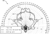
- Figure 4 is a field strength graph showing the effect of the structure of the antenna module and the radiation reinforcing member according to an embodiment of the present invention.
- 5 is a field strength graph showing the difference according to the curvature of the radiation reinforcing member according to an embodiment of the present invention.
- FIG. 6 is a diagram showing the structure and arrangement of the radiation reinforcing member according to an embodiment of the present invention.
- FIG. 7 is a plan view illustrating the radiation reinforcing member of FIG. 6 as viewed from above.
- FIG. 7 is a plan view illustrating the radiation reinforcing member of FIG. 6 as viewed from above.
- FIG. 8 is a block diagram illustrating a display device according to an embodiment of the present invention.
- FIG. 1 is a block diagram illustrating an antenna device according to an embodiment of the present invention.
- the antenna device 100 processes an antenna module 110 that wirelessly receives a signal propagating through a free space and a signal received by the antenna module 110. And a communication unit 130 for outputting a signal processed by the signal processing unit 120 to the outside.
- the antenna device 100 may not only receive a signal but also transmit a signal.
- the signal processor 120 processes a signal received by the communication unit 130, and the antenna module 110 frees the processed signal. It can transmit by releasing to space.
- the antenna module 110 includes one or more antenna elements for transmitting and receiving signals.
- the antenna module 110 according to the present embodiment is provided to transmit and receive a millimeter wave, that is, mmWave, which is a signal of an ultra-high frequency band of 30 GHz or more.
- mmWave is a signal in the frequency band of 30 to 300 GHz with a wavelength of only 1 to 10 mm.
- mmWave has very high propagation straightness depending on the characteristics of a signal whose wavelength is shorter as the number of vibrations increases.
- mmWave has a relatively good signal quality, it may be difficult to propagate relatively far due to the large number of vibrations.
- frequency exhaustion which is no longer able to convey huge amounts of information at frequencies below 10 GHz.
- mmWave is proposed as an alternative to this situation, and the increase in security and exclusion of interference effects, which can be achieved because the radio wave reaches only a few meters, is also highlighted.
- the radiation gain of the direction in which the signal is expected to be received for example, the front direction of the antenna module 110 is relatively large. It must be prepared. In this case, in the electric field strength curve of the electromagnetic wave radiated 360 degrees in the antenna module 110, the curve of the electric field strength with respect to the radial direction of the antenna module 110 is relatively Appears long.
- the curve of the electric field strength with respect to the radially oriented direction of the antenna module 110 for example, the front direction, is referred to as the main lobe.
- the curve of the electric field strength with respect to the left and right directions in the radial direction of the antenna module 110 is a side lobe
- the curve of the electric field strength with respect to the rear direction opposite to the radial direction of the antenna module 110 is a back lobe. It is called a back lobe.
- the antenna module 110 includes a phased array antenna that supports the beam forming function.
- the structure of the phased array antenna will be described later.
- the signal processor 120 may be a combination of a chipset, a microprocessor, a CPU, or the like, a circuit structure, or an SOC.
- the signal processor 120 is provided to support various functions according to the requirements for the antenna device 100.
- the signal processor 120 may support a modulation and demodulation function.
- the signal processor 120 demodulates a signal received by the antenna module 110, transmits the signal to the outside through the communication unit 130, and receives the signal through the communication unit 130.
- the modulated signal may be transmitted to the antenna module 110.
- the communication unit 130 includes a communication interface circuit for transmitting and receiving signals to and from the outside.
- the communication unit 130 includes a wired port to which a cable is connected, or a wireless communication chipset for wireless communication.
- the communicator 130 connects with the hub 10 according to a communication method such as Wi-Fi or Bluetooth, and the TV, home appliances, and other electronic devices through the hub 10. It can communicate with the same external device 20.
- the hub 10 is a device that relays communication between various external devices 20 in the system including the antenna device 100, and the type thereof is not limited.
- the hub 10 may be implemented as a device such as an access point (AP), a router, or an Internet of Things (IoT) hub.
- AP access point
- IoT Internet of Things
- the independent antenna device 100 including the antenna module 110 has been described, but the spirit of the present invention is not limited thereto.
- the idea of the present invention is related to the improvement of the radiation performance of the antenna module 110, it is not necessarily limited to the case where the antenna module 110 is implemented as an independent device.
- the idea of the present invention can be applied to an antenna module installed in an image processing apparatus such as a TV or a set-top box.
- FIG 2 is an exemplary view showing a part of the structure of the antenna module according to the present embodiment.
- the antenna module 200 is implemented as a phased array antenna supporting a beamforming function, and includes a substrate 210 and a plurality of antennas spaced apart from each other on one surface of the substrate 210.
- Device 220 The plurality of antenna elements 220 are provided as conductors to enable signal transmission and reception, and are disposed on one surface of the substrate 210 along the direction in which the antenna module 200 transmits and receives signals. That is, in the antenna element 220, the antenna module 200 is disposed on the substrate 210 in the radial direction, and when the electric field strength is measured, the main lobe appears long in the radial direction.
- the number of antenna elements 220 mounted on the substrate 210, the arrangement form of the plurality of antenna elements 220, and the separation distance between two adjacent antenna elements 220 may include the antenna module 200.
- Various design changes may be applied according to signal characteristics to be transmitted and received, and the inventive concept is not limited.
- the plurality of antenna elements 220 are arranged in an arrangement, when the phases of the antenna elements 220 are adjusted in one direction, the radiation gain in the corresponding direction becomes stronger. That is, when the phase of each antenna element 220 is provided to be adjusted, the direction in which the radiation gain of the antenna module 200 is relatively strong can be adjusted according to the adjustment.
- the phase shifter 230 may implement beamforming by electronically converting a phase of a current and a voltage applied to each antenna element 220 at high speed. That is, the phase shifter 230 adjusts the direction in which the transmission and reception sensitivity of the antenna module 200 is relatively high by changing the phase of each antenna element 220.
- the electric field strength is measured while the phase shifter 230 sequentially varies the phase of each antenna element 220 as described above, the main lobe appears long in a range of a predetermined angle around the radial direction.
- the radiation directing direction is a direction in which a normal line of the plate surface of the substrate 210 on which the plurality of antenna elements 220 is mounted is directed.
- the antenna module 200 has a phased array antenna structure, thereby ensuring the reception performance of signals in the mmWave frequency band in the radial direction.
- the antenna module 200 of this structure is guaranteed the radiation gain in the radial direction, but the radiation gain for the left and right sides of the radiation direction can be relatively low.
- the main lobe along the radial direction along the axis of 0 degrees of azimuth appears as a relatively long curve, while the side lobe around the axis about 60 degrees to the left and right of the 0 degree axis is relatively short. It appears as a curve. This means that the reception performance of the signal in the direction of about 60 degrees left and right relatively decreases.
- a structure or method may be needed to reinforce the radiation gain of the side lobe in the antenna module 200.
- the related art there is a structure in which a reflector having a predetermined curvature is installed in a direction facing the radiation directing direction of the antenna module.
- the antenna module in the related art does not necessarily include a phased array antenna structure.
- the structure of the related technology is a design method of relatively narrowing the reception angle of a signal according to the curvature of the reflector and maximizing the reception gain of the antenna module.
- the structure of the present technology has a high radiation gain of up to 30 dBi or more, instead of having a narrow operating angle of less than 30 degrees.
- the structure of the present technology is not suitable for mmWave applications in in-room environments where high azimuth coverage and high azimuth coverage performance must be obtained at the same time because the azimuth coverage is low instead of the high radiation gain. have.
- FIG. 3 is a perspective view showing the arrangement of the reinforcing member for reinforcing the radiation gain of the antenna module according to an embodiment of the present invention.
- the antenna module 310 has a phased array antenna structure, and the structure thereof has been described above.
- the direction of the radiation direction of the electromagnetic wave for transmitting and receiving a signal is determined according to which direction the plate surface faces.
- a hemispherical radio wave reinforcing member or radiation reinforcing member 320 is installed at the rear of the antenna module 310.
- the radiation reinforcing member 320 is disposed in a direction opposite to the radiation directing direction of the antenna module 310.
- the radiation reinforcing member 320 is disposed on an opposite side of the radiation directing surface of the antenna module 310.
- the radiation reinforcing member 320 is disposed so that the concave curved surface of the radiation reinforcing member 320 surrounds the rear of the antenna module 310.
- the radiation reinforcing member 320 includes a conductor such as metal on at least a portion of the curved surface surrounding the antenna module 310.
- the radiation reinforcing member 320 may be formed of an entire conductor surface.
- the radiation reinforcing member 320 may include a dielectric when a part includes a conductor.
- the radiation reinforcing member 320 may be formed of a conductive portion of the curved surface surrounding the antenna module 310 and the remaining portion of the curved surface may be formed of a dielectric material, or may be provided in a structure in which the outside of the dielectric is coated with a conductive material. have.
- the radiation reinforcing member 320 is provided in a hemispherical shape with one curvature.
- the distance d between the radiation reinforcing member 320 and the antenna module 310 does not exceed the preset distance.
- the distance d may be provided not to exceed the focal length of the curved surface of the radiation reinforcing member 320, so that the radiation reinforcing member 320 may improve the left and right radiation gain effect of the antenna module 310.
- the distance d is provided within a range of a near-field by the antenna module 310.
- the near field is defined as (2D ⁇ 2) / ⁇ .
- the antenna module 310 receives a signal in a frequency band of 60 GHz, the near field may be defined within an area of about 11 cm in diameter with respect to the antenna module 310.
- the distance d is provided within a radius of 6.5 cm.
- the radiation length D of the antenna may represent the area of the antenna module 310.
- near field radiation loss of the antenna's radiation performance is classified into components that do not contribute to the antenna's transmit / receive performance.
- the radiation reinforcing member 320 as a conductor in the near-field region of the antenna module 310, the radiation performance of the side of the antenna module 310 is changed without compromising the existing radiation performance. This is because the coupling effect of electromagnetic waves is generated between the antenna module 310 and the radiation reinforcing member 320 in the near field, thereby improving the radiation performance of the antenna module 310.
- the side radiation performance of the antenna module 310 may be improved by only installing the radiation reinforcing member 320 without changing the structure or controlling the antenna module 310.
- Figure 4 is a field strength graph showing the effect of the structure of the antenna module and the radiation reinforcing member according to an embodiment of the present invention.
- a field strength graph 400 of the antenna may appear.
- the electric field strength graph 400 provides a curve indicating the electric field strength of the antenna on the coordinates of the azimuth angle so as to determine the radiation gain of the antenna.
- the central axis passing through the angle 0 degrees in the azimuth coordinate of the field strength graph 400 represents the main radial direction of the antenna module, and a curve within a predetermined range on the left and right about the central axis forms the main lobe.
- negative angles indicate left directions and positive angles indicate right directions, respectively.
- the first curve 410 represents the electric field strength when the antenna module is used alone
- the second curve 420 represents the electric field strength when the antenna module and the radiation reinforcing member is used according to an embodiment of the present invention
- the third curve 430 represents the electric field strength when a structure in which a reflector having a predetermined curvature is installed in a direction facing the radial direction of the antenna module is used according to the related art. Since the graph 400 is for comparing the electric field strength curves between the three curves 410, 420, and 430, the description of the experimental environment is omitted.
- the length of the left and right side lobes are relatively short compared to the length of the main lobe. This means that when the antenna module is used alone, the radiation gain on the left and right sides of the antenna module is relatively lower than the radiation gain on the front of the antenna module.
- the second curve 420 is due to the structure according to the present embodiment for overcoming the problem of the first curve 410.
- the main lobe of the second curve 420 has a relatively ripple
- the main lobe of the second curve 420 has a length similar to that of the main lobe of the first curve 410.
- the length of the left and right side lobes 421 of the second curve 420 is much longer than the side lobes of the first curve 410.
- the length of the side lobe 421 is relatively increased in the range of the left and right 60 to 70 degrees azimuth of the second curve 420.
- the third curve 430 is according to the structure in which the curved surface of the reflector is disposed in the radial direction of the antenna module according to the related art, and the main lobe has a longer length instead of a relatively narrow width of the main lobe.
- Lobes appear relatively short in length. This means that the radiation performance is good for a range of specific azimuth angles, while that of the other azimuth angles is considerably poor.
- the related art is difficult to apply when good spinning performance is required for a relatively wide azimuth range.
- the curvature of the radiation reinforcing member may be applied various values depending on the characteristics and design methods required for the antenna module. Although the numerical value of the specific curvature does not limit the idea of the present invention, the shape of the electric field strength may appear differently according to the curvature, and the curvature is determined in consideration of this.
- 5 is a field strength graph showing the difference according to the curvature of the radiation reinforcing member according to an embodiment of the present invention.
- a field strength graph 500 of the antenna may appear.
- Basic content of the field strength graph 500 has already been described in the foregoing embodiment.
- the first curve 510 indicates the electric field strength when the antenna module is used alone
- the second curve 520 indicates the electric field strength when the radial reinforcing member having a radius of curvature of 60 mm is applied to the antenna module.
- Reference numeral 530 denotes the electric field strength when the radial reinforcing member having a radius of curvature of 75 mm is applied to the antenna module.
- the length of the left and right side lobes is relatively short compared to the length of the main lobe.
- the length of the main lobe is substantially similar to that of the first curve 510, whereas the side lobe is reinforced significantly than that of the first curve 510.
- the radiation gain of the second curve 520 is remarkably improved in the range of 60 to 70 degrees azimuth.
- the third curve 530 to which the curvature different from that of the second curve 520 is applied is different from that of the second curve 520.
- the main lobe of the third curve 530 is not significantly different from the case of the first curve 510 and the second curve 520, while the side lobe is hardly reinforced unlike the case of the second curve 520. It is not shown.
- the third curve 530 is slightly reinforced in the range of the left and right 30 degrees to 50 degrees azimuth angle compared to the first curve 510, and the first curve 510 rather than the range of the left and right 60 to 70 degrees azimuth angle. The radiation gain is lower than).
- the curvature is determined with this in mind. That is, in order for the coupling effect described above to be remarkable, the radiation reinforcing member is simply located in the near field of the antenna module. For example, if the radiation reinforcing member is close to the plane, the reinforcing effect of the side lobe does not appear. If the radiation reinforcing member has a radius of curvature of less than a predetermined value, the reinforcement of the radiation gain of the side lobe is relatively large. Effect.
- the radiation reinforcing member may include a plane partially in the microscopic view, but is provided to have a substantial curvature in the macroscopic view.
- the radial reinforcing member has one curvature.
- the spirit of the present invention is not limited by this example, and the radiation reinforcing member may be provided such that surfaces having different curvatures are spaced apart from each other or overlap each other. By this structure, the coupling gain can be maximized to improve the radiation gain.
- FIG. 6 is a diagram showing the structure and arrangement of the radiation reinforcing member according to an embodiment of the present invention.
- the radiation reinforcing member 630 is disposed at the rear of the antenna module 610 supported by the support 620.
- the radiation reinforcing member 630 includes a plurality of reinforcement regions 631, 632, and 633 having different curvatures from each other rather than one curvature.
- the radiation reinforcing member 630 may form, for example, an outer shape of the radiation reinforcing member 630 and each reinforcement region 631, 632, and 633 including a conductor may be formed outside the base including the dielectric. .
- Each reinforcement region 631, 632, and 633 may be adjacent to each other or may be spaced apart from each other.
- each of the reinforcement regions 631, 632, and 633 is provided to have different curvatures, so that the radiation gain can be relatively improved as compared with the case in which the radiation reinforcing member has a single curvature as in the previous embodiment.
- Each of the reinforcement regions 631, 632, and 633 may be formed on the front surface facing the antenna module 610 in the radiation reinforcement member 630, but may be formed on the rear surface opposite to the front surface of the radiation reinforcement member 630. It may be formed.
- the front and rear surfaces of the radiation reinforcing member 630 have different curvatures, so that the reinforcement regions 631, 632, and 633 are installed on the front and rear surfaces, respectively, so that the radiation reinforcing member 630 has a more diverse curvature. 631, 632, and 633.
- portions other than the reinforcement regions 631, 632, and 633 of the radiation reinforcing member 630 are provided as dielectrics through which electromagnetic waves can pass.
- FIG. 7 is a plan view illustrating the radiation reinforcing member of FIG. 6 viewed from above.
- FIG. 7 is a plan view illustrating the radiation reinforcing member of FIG. 6 viewed from above.
- the radiation reinforcing member 720 is installed at the rear of the antenna module 710.
- the base 721 including the dielectric in the radiation reinforcing member 720 has a central front surface having a first predetermined curvature, left and right front surfaces having a second predetermined curvature, and a rear surface having a third predetermined curvature.
- at least two of the first curvature, the second curvature, and the third curvature have different curvature values.
- the radiation reinforcing member 720 may include a first reinforcing region 722 provided at the center front surface of the base 721, a second reinforcing region 723 provided at left and right front sides of the base 721, and a base 721. It includes a third reinforcement area 724 installed on the back. Each reinforcement region 722, 723, 724 is formed on the outer surface of the base 721, and each reinforcement region 722, 723, 724 has a curvature corresponding to the outer surface of the base 721. Each reinforcement region 722, 723, 724 includes a conductor, and the curved surface of each reinforcement region 722, 723, 724 is arranged to surround the antenna module 710.
- the straight lines connecting the antenna module 710 and the center of each of the reinforcement regions 722, 723, and 724 are preferably spaced apart from each other. That is, a path of electromagnetic waves is secured between each of the reinforcement areas 722, 723, and 724 and the antenna module 710, so that the coupling effect by each of the reinforcement areas 722, 723, and 724 may be improved. If the third reinforcement region 724 on the rear side of the base 721 when viewed from the antenna module 710 side overlaps the first reinforcement region 722 or the second reinforcement region 723, the third reinforcement region ( The path of electromagnetic waves between the 724 and the antenna module 710 is interfered by the first reinforcement region 722 or the second reinforcement region 723. In this case, the coupling effect by the third reinforcement region 724 is insufficient.
- the respective reinforcement regions 722, 723, and 724 are arranged so as not to overlap as much as possible to maximize the coupling effect.
- the antenna module of the structure to which the radiation reinforcing member is applied is implemented as an independent antenna device.
- the apparatus to which the idea of the present invention is applied is not limited thereto.
- FIG. 8 is a block diagram illustrating a display device according to an embodiment of the present invention.
- the display apparatus 800 is implemented as a TV, and includes an antenna module 810 for receiving a broadcast signal and a broadcast signal received at the antenna module 810 for a specific channel.
- a display for displaying a broadcast image according to a tuner 820 tuned to a frequency of?,
- a signal processor 830 for processing a broadcast signal tuned by the tuner 820, and a broadcast signal processed by the signal processor 830?
- a unit 840 and a speaker 850 for outputting broadcast audio according to the broadcast signal processed by the signal processing unit 830.
- the antenna module 810 has a structure and a function as described in the foregoing embodiment, and further includes a radiation reinforcing member to improve the radiation gain.
- the radiation reinforcing member can be applied to the previous embodiment, so a detailed description thereof will be omitted.
- the tuner 820 tunes and demodulates an RF signal received by the antenna module 810 to a specific frequency.
- the tuner 820 is implemented as a hardware chipset including a tuning circuit for tuning an RF signal, an ADC for converting a tuned analog signal into a digital signal, and a demodulator for demodulating the tuned digital signal.
- the ADC or demodulator may be implemented in a separate configuration from the tuner 820.
- the signal processor 830 processes the demodulated digital signal according to various processes, and may be implemented as an SOC or a signal processing board in which a module for performing each process is embedded.
- the signal processor 830 includes a module such as a demux, a decoder, a scaler, and the like.
- the signal processing unit 830 may be configured to include a CPU in the SOC.
- the device including the antenna module 810 is not limited to the display device 800, and may be a home appliance such as a refrigerator or a communication relay device such as a hub, an AP, and a repeater.
- Methods according to an exemplary embodiment of the present invention may be implemented in the form of program instructions that can be executed by various computer means and recorded in a computer readable medium.
- Such computer-readable media may include, alone or in combination with the program instructions, data files, data structures, and the like.
- a computer readable medium may be volatile or nonvolatile, such as a storage device such as a ROM, whether or not removable or rewritable, or a memory such as, for example, a RAM, a memory chip, a device, or an integrated circuit.
- a storage device such as a ROM, whether or not removable or rewritable
- a memory such as, for example, a RAM, a memory chip, a device, or an integrated circuit.
- CD or DVD, magnetic disk or magnetic tape and the like can be stored in a storage medium that is optically or magnetically recordable and simultaneously readable by a machine (eg computer).
- a memory that can be included in a mobile terminal is an example of a machine-readable storage medium suitable for storing a program or programs containing instructions for implementing embodiments of the present invention.
- the program instructions recorded on the storage medium may be those specially designed and constructed for the present invention, or may be known and available to those skilled in the art of computer software.
Landscapes
- Engineering & Computer Science (AREA)
- Physics & Mathematics (AREA)
- Electromagnetism (AREA)
- Computer Networks & Wireless Communication (AREA)
- Manufacturing & Machinery (AREA)
- Variable-Direction Aerials And Aerial Arrays (AREA)
Abstract
본 발명의 실시예에 따른 안테나장치는, 무선신호를 송수신하도록 제1방향의 방사 지향면을 가지는 안테나모듈과; 안테나모듈의 방사 성능을 증폭시키도록 기 설정된 거리 이내에 안테나모듈로부터 제1방향의 반대방향인 제2방향에 배치되고 안테나모듈에 대해 오목한 곡면을 가지는 도전체를 포함한 전파보강부재를 포함하는 것을 특징으로 한다.
Description
본 발명은 소정의 무선신호를 송수신하는 안테나장치에 관한 것으로서, 상세하게는 안테나모듈에 의해 mmWave(millimeter wave)와 같은 초고주파의 신호를 송수신함에 있어서 해당 안테나모듈의 방사성능을 향상시키도록 구조가 개선된 안테나장치에 관한 것이다.
소정의 정보를 특정 프로세스에 따라서 연산 및 처리하기 위해, 연산을 위한 CPU, 칩셋, 메모리 등의 전자부품들을 기본적으로 포함하는 전자장치는, 처리 대상이 되는 정보가 무엇인지에 따라서 다양한 종류로 구분될 수 있다. 예를 들면, 전자장치에는 범용의 정보를 처리하는 PC나 서버 등의 정보처리장치가 있고, 영상 정보를 처리하는 영상처리장치가 있다. 영상처리장치는 외부로부터 수신되는 영상신호 또는 영상데이터를 다양한 영상처리 프로세스에 따라서 처리한다. 영상처리장치는 처리된 영상데이터를 자체 구비한 디스플레이부에 영상으로 표시하거나, 또는 디스플레이부를 구비한 별도의 외부장치에서 영상으로 표시되도록 이 처리된 영상데이터를 해당 외부장치에 출력한다. 디스플레이부를 가지지 않은 영상처리장치의 예시로는 셋탑박스가 있다. 디스플레이부를 가진 영상처리장치를 특히 디스플레이장치라고 지칭하며 그 예시로는 TV, 휴대용 멀티미디어 재생기, 태블릿(tablet), 모바일 폰(mobile phone) 등이 있다.
상기한 장치들은 해당 장치 단독으로 고립되어 동작하기보다는, 네트워크를 통해 외부의 장치들과 소정의 신호를 송수신함으로써 해당 신호의 처리에 따른 동작을 수행한다. 신호의 전송은 유선통신을 통해서도 가능하지만, 현재 기술은 무선통신 방식으로 신호가 전송되도록 하는 방향으로 발전하고 있다. 무선으로 신호를 전송하는 방식의 대표적인 기술이 안테나이다.
무선통신에서 신호는 자유공간(free space)을 통해 이동하는 바, 안테나는 자유공간에 신호를 방출하는 한편, 자유공간에 방출된 신호를 캡쳐하는 최종 단말로서의 역할을 수행한다. 안테나는 독립적인 장치로서 구현될 수 있고, 영상처리장치와 같은 메인 장치의 구성요소로서 존재할 수도 있다.
그런데, 현재 무선통신의 사용 증가에 따른 주파수 고갈 현상과 같은 여러 요인으로 인해, mmWave와 같은 초고주파 대역의 신호를 사용할 필요성이 제기되고 있다. 그런데, 신호의 특성 상 주파수에 따라서 파장은 반비례하므로, 전파의 성질 또한 주파수 상승에 따라서 변화하게 된다. 이는, 과거 상대적으로 낮은 주파수의 신호에 대응하는 구조의 안테나로 mmWave을 송수신한다면 문제가 될 수 있다.
이에, mmWave 등의 신호를 송수신하기 위한 안테나에 있어서, 전반적으로 방사 성능을 개선하기 위한 구조가 필요할 수 있다.
본 발명의 실시예에 따른 안테나장치는, 무선신호를 송수신하도록 제1방향의 방사 지향면을 가지는 안테나모듈과; 상기 안테나모듈의 방사 성능을 증폭시키도록 기 설정된 거리 이내에 상기 안테나모듈로부터 상기 제1방향의 반대방향인 제2방향에 배치되고 상기 안테나모듈에 대해 오목한 곡면을 가지는 도전체를 포함한 전파보강부재를 포함하는 것을 특징으로 한다. 이로써, 안테나장치는 mmWave를 송수신하고 빔포밍을 지원하는 안테나모듈에 대해 좌우측의 방사 성능을 보강시킴으로써, 무선신호의 송수신 성능을 향상시킬 수 있다.
여기서, 상기 도전체 및 상기 안테나모듈 사이의 상기 기 설정된 거리는, 상기 곡면의 초점거리를 초과하지 않게 마련될 수 있다.
또한, 상기 도전체 및 상기 안테나모듈 사이의 상기 기 설정된 거리는, 상기 안테나모듈의 방사 길이 및 상기 안테나모듈의 동작 주파수에 따른 파장에 대응하게 마련될 수 있다. 이로써, 안테나장치는 도전체 및 안테나모듈의 커플링 효과를 구현할 수 있다.
또한, 상기 안테나모듈은 상호 이격되게 배치된 복수의 안테나소자를 가지는 위상 배열 안테나를 포함할 수 있다. 이로써, 안테나모듈은 빔 포밍을 구현할 수 있다.
여기서, 상기 안테나모듈은 밀리미터파에 따른 상기 무선신호를 송수신하게 마련될 수 있다.
또한, 상기 복수의 안테나소자에 대해 인가되는 전압의 위상을 개별적으로 조정하는 제어회로를 더 포함할 수 있다.
또한, 상기 전파보강부재는 복수의 상기 도전체를 포함하며, 상기 복수의 도전체 각각의 곡률은 서로 상이하게 마련될 수 있다. 이로써, 안테나장치는 각 도전체에 의한 커플링 효과를 극대화시킴으로써, 안테나모듈의 방사 성능을 크게 향상시킬 수 있다.
여기서, 상기 안테나모듈에 대한 상기 복수의 도전체의 곡면의 중심 축선은 서로 상이하게 마련될 수 있다. 이로써, 안테나장치는 각 도전체에 의한 커플링 효과가 간섭받는 것을 가능한 한 방지할 수 있다.
또한, 상기 전파보강부재는, 유전체를 포함하는 베이스와; 상기 안테나모듈을 향하는 상기 베이스의 전면 상에 형성되며 제1곡률을 가진 제1도전체와; 상기 베이스의 상기 전면의 반대쪽에 위치한 상기 베이스의 후면 상에 형성되며 제2곡률을 가진 제2도전체를 포함할 수 있다.
도 1은 본 발명의 실시예에 따른 안테나장치의 구성 블록도이다.
도 2는 본 실시예에 따른 안테나모듈의 구조를 일부 나타내는 예시도이다.
도 3은 본 발명의 실시예에 따른 안테나모듈의 방사 이득을 보강하는 보강부재의 배치 형태를 나타내는 사시도이다.
도 4는 본 발명의 실시예에 따른 안테나모듈 및 방사보강부재의 구조의 효과를 나타내는 전계강도 그래프이다.
도 5는 본 발명의 실시예에 따른 방사보강부재의 곡률에 따른 차이를 나타내는 전계강도 그래프이다.
도 6은 본 발명의 실시예에 따른 방사보강부재의 구조와 배치를 나타내는 사이도이다.
도 7은 도 6의 방사보강부재를 위에서 본 모습을 나타내는 평면도이다.
도 8은 본 발명의 실시예에 따른 디스플레이장치의 구성 블록도이다.
이하에서는 첨부도면을 참조하여 본 발명에 따른 실시예들에 관해 상세히 설명한다. 이하 실시예들의 설명에서는 첨부된 도면들에 기재된 사항들을 참조한다. 또한, 실시예에서는 본 발명의 사상과 직접적인 관련이 있는 구성들에 관해서만 설명하며, 그 외의 구성에 관해서는 설명을 생략한다. 그러나, 본 발명의 사상이 적용된 장치 또는 시스템을 구현함에 있어서, 이와 같이 설명이 생략된 구성이 불필요함을 의미하는 것이 아님을 밝힌다. 실시예에서 "포함하다" 또는 "가지다"와 같은 용어는 명세서 상에 기재된 특징, 숫자, 단계, 동작, 구성요소 또는 이들의 조합이 존재함을 지정하기 위한 것이며, 하나 이상의 다른 특징, 숫자, 단계, 동작, 구성요소 또는 이들의 조합이 존재하거나 부가되는 가능성을 배제하는 것은 아니다.
또한, 각 도면을 참조하여 설명하는 실시예들은 특별한 언급이 없는 한 상호 배타적인 구성이 아니며, 하나의 장치 내에서 복수 개의 실시예가 선택적으로 조합되어 구현될 수 있다. 이러한 복수의 실시예의 조합은 본 발명의 기술분야에서 숙련된 기술자가 본 발명의 사상을 구현함에 있어서 임의로 선택되어 적용될 수 있다.
도 1은 본 발명의 실시예에 따른 안테나장치의 구성 블록도이다.
도 1에 도시된 바와 같이, 본 실시예에 따른 안테나장치(100)는 자유공간을 통해 전파되는 신호를 무선으로 수신하는 안테나모듈(110)과, 안테나모듈(110)에 의해 수신되는 신호를 처리하는 신호처리부(120)와, 신호처리부(120)에 의해 처리되는 신호를 외부로 출력하는 통신부(130)를 포함한다. 안테나장치(100)는 신호의 수신 뿐만 아니라 신호의 송신도 가능한 바, 예를 들면 통신부(130)에 수신되는 신호를 신호처리부(120)가 처리하고, 처리된 신호를 안테나모듈(110)이 자유공간으로 방출함으로써 송신할 수 있다.
안테나모듈(110)은 신호를 송수신하기 위한 하나 이상의 안테나소자를 포함한다. 본 실시예에 따른 안테나모듈(110)은 30GHz 이상의 초고주파 대역의 신호인 밀리미터파, 즉 mmWave를 송수신하게 마련된다. mmWave는 30 내지 300GHz의 주파수 대역의 신호로서 파장은 1 내지 10mm에 불과하다.
mmWave는 기본적으로 진동회수가 많을수록 파장이 짧아지는 신호의 특성에 따라서, 전파의 직진성이 매우 높다. 따라서, mmWave는 신호의 품질이 상대적으로 좋은 반면, 많은 진동회수로 인해 상대적으로 멀리 전파되기 곤란할 수 있다. mmWave가 사용되는 여러 요인 중 하나로는 주파수 고갈 사태가 있는데, 현재의 10GHz 이하의 주파수로는 더 이상 엄청난 양의 정보를 전달하기에 곤란해지고 있다. mmWave는 이러한 사태의 대안으로 제안되고 있으며, 전파 도달 거리가 수 미터에 불과하기 때문에 얻을 수 있는 보안성 증가, 간섭 영향 배제 효과 또한 큰 장점으로 부각되고 있다.
안테나모듈(110)이 상대적으로 파장이 짧고 주파수가 높은 mmWave의 신호를 수신하기 위해서는, 신호가 수신되는 것으로 예상되는 방향, 예를 들면 안테나모듈(110)의 전방 방향에 대한 방사 이득이 상대적으로 크게 마련되어야 한다. 이 경우에, 안테나모듈(110)에서 360도 전방향으로 복사되는(radiated) 전자기파의 전계강도(electric field strength) 곡선에서, 안테나모듈(110)의 방사 지향 방향에 대한 전계강도의 곡선이 상대적으로 길게 나타난다.
안테나모듈(110)의 방사 지향 방향, 예를 들면 전방 방향에 대한 전계강도의 곡선은 메인 로브(main lobe)라고 지칭한다. 안테나모듈(110)의 방사 지향 방향의 좌우측 방향에 대한 전계강도의 곡선은 사이드 로브(side lobe), 안테나모듈(110)의 방사 지향 방향의 반대방향인 후방 방향에 대한 전계강도의 곡선은 백 로브(back lobe)라고 지칭한다.
그런데, 신호를 정상적인 품질로 수신할 수 있는 범위를 넓히기 위해서는, 해당 방향에 대한 방위각 또한 넓어짐으로써 메인 로브의 폭이 넓게 나타나야 한다. 이를 실현하기 위해 빔 포밍(beam-forming) 기능이 요구되는 바, 안테나모듈(110)은 빔 포밍 기능을 지원하는 위상 배열 안테나(Phased Array Antenna)를 포함한다. 위상배열 안테나의 구조에 관해서는 후술한다.
신호처리부(120)는 칩셋, 마이크로 프로세서, CPU 등의 조합이거나, 회로 구조이거나, 또는 SOC로 구현된다. 신호처리부(120)는 안테나장치(100)에 대한 요구 사항에 따라서 다양한 기능을 지원하도록 마련된다. 예를 들면, 신호처리부(120)는 변조 및 복조 기능을 지원할 수 있는 바, 안테나모듈(110)에 수신되는 신호를 복조하여 통신부(130)를 통해 외부로 전송하고, 통신부(130)를 통해 수신되는 신호를 변조하여 안테나모듈(110)로 전달할 수 있다.
통신부(130)는 외부와 신호의 송수신을 수행하기 위한 통신 인터페이스 회로를 포함하는 바, 예를 들면 케이블이 접속되는 유선 포트, 또는 무선통신을 위한 무선통신칩셋 등을 포함한다. 통신부(130)가 무선통신칩셋을 포함하는 경우에, 통신부(130)는 와이파이 또는 블루투스 등과 같은 통신방식에 따라서 허브(10)와 접속하며, 허브(10)를 통해 TV, 가전, 기타 전자기기 등과 같은 외부장치(20)와 통신할 수 있다.
허브(10)는 안테나장치(100)를 포함하는 시스템 내의 다양한 외부장치(20)들 사이의 통신을 중계하는 장치로서, 그 종류는 한정되지 않는다. 예를 들면, 허브(10)는 AP(access point), 라우터(router), IoT(Internet of Things) 허브 등의 장치로 구현될 수 있다.
본 실시예에서는 안테나모듈(110)을 포함하는 독립적인 안테나장치(100)에 관해 설명하였지만, 본 발명의 사상이 이에 한정되는 것은 아니다. 차후 실시예에서도 설명하겠지만, 본 발명의 사상은 안테나모듈(110)의 방사 성능의 향상에 관련된 사항인 바, 반드시 안테나모듈(110)이 독립적인 장치로 구현되는 경우에만 한정되지 않는다. 예를 들어, TV나 셋탑박스와 같은 영상처리장치에 설치되는 안테나모듈의 경우에도 본 발명의 사상을 적용할 수 있다.
이하, 안테나모듈(110)의 구조에 관해 설명한다.
도 2는 본 실시예에 따른 안테나모듈의 구조를 일부 나타내는 예시도이다.
도 2에 도시된 바와 같이, 안테나모듈(200)은 빔 포밍 기능을 지원하는 위상 배열 안테나로 구현되는 바, 기판(210)과, 기판(210)의 일면 상에 상호 이격되게 배치된 복수의 안테나소자(220)를 포함한다. 복수의 안테나소자(220)는 신호 송수신이 가능하도록 도체로 마련되며, 안테나모듈(200)이 신호를 송수신하기 위한 방향을 항하는 기판(210)의 일면 상에 배치된다. 즉, 안테나소자(220)는 안테나모듈(200)이 방사 지향 방향을 향해 기판(210) 상에 배치되며, 전계강도를 계측할 경우에 해당 방사 지향 방향을 향해 메인 로브가 길게 나타난다.
기판(210) 상에 장착되는 복수의 안테나소자(220)의 수, 복수의 안테나소자(220)의 배치 형태, 인접하는 두 안테나소자(220) 사이의 이격거리 등은, 안테나모듈(200)이 송수신하는 신호 특성에 따라서 다양한 설계 변경이 적용될 수 있는 사항인 바, 본 발명의 사상을 한정하는 것이 아니다.
이와 같이 복수의 안테나소자(220)가 배열 형태로 구성한 상태에서 각 안테나소자(220)의 위상을 일 방향으로 조정할 경우, 해당 방향에 대한 방사 이득이 강해진다. 즉, 각 안테나소자(220)의 위상이 조정될 수 있게 마련되면, 안테나모듈(200)의 방사 이득이 상대적으로 강한 방향은 해당 조정에 따라서 조절될 수 있게 된다.
위상변위기(230)는 각 안테나소자(220)에 인가되는 전류, 전압의 위상을 전자적으로 고속 변환시킴으로써 빔 포밍을 구현시킬 수 있다. 즉, 위상변위기(230)는 각 안테나소자(220)가 위상을 가변함으로써, 안테나모듈(200)의 송수신 감도가 상대적으로 높은 방향을 조정한다. 이와 같이 위상변위기(230)가 각 안테나소자(220)의 위상을 순차적으로 가변하는 동안에 전계강도를 계측하면, 방사 지향 방향을 중심으로 하여 메인 로브가 소정 각도의 범위로 길게 나타난다. 여기서, 방사 지향 방향은 복수의 안테나소자(220)가 장착되는 기판(210)의 판면의 법선이 향하는 방향이다.
이로써, 안테나모듈(200)은 위상 배열 안테나 구조를 가짐으로써, 방사 지향 방향을 통한 mmWave 주파수대의 신호의 수신 성능을 확보할 수 있다.
그런데, 이러한 구조의 안테나모듈(200)은 방사 지향 방향의 방사 이득은 보장되지만, 방사 지향 방향의 좌우측에 대한 방사 이득은 상대적으로 떨어질 수 있다. 전계강도 그래프 상에서 보면, 방위각 0도의 축선을 중심으로 하는 방사 지향 방향에 따른 메인 로브는 상대적으로 긴 곡선으로 나타나는 반면, 0도 축선 좌우의 60도 정도의 축선을 중심으로 하는 사이드 로브는 상대적으로 짧은 곡선으로 나타난다. 이는, 좌우 60도 정도의 방향을 통한 신호의 수신 성능이 상대적으로 떨어진다는 것을 의미한다.
이러한 점을 극복하기 위해, 안테나모듈(200)에 사이드 로브의 방사 이득을 보강하기 위한 구조 또는 방법이 필요할 수 있다.
한편, 관련 기술에서는 안테나모듈의 방사 지향 방향과 마주하는 방향으로 소정의 곡률을 가진 반사판이 설치되는 구조가 있다. 관련 기술에서의 안테나모듈은 반드시 위상 배열 안테나 구조를 포함하는 것은 아니다. 이와 같은 관련 기술의 구조는 반사판의 곡률에 따라서 신호의 수신 각도를 상대적으로 좁히고, 안테나모듈의 수신 이득을 극대화시키는 설계방식이다. 일반적으로, 본 관련 기술의 구조는 30도 미만의 좁은 동작 각도를 가지는 대신, 최대 30dBi 이상의 높은 방사 이득을 가진다.
그러나, 본 관련 기술의 구조는 방사 이득이 높은 대신에 방위각 커버리지(Azimuth coverage)가 낮아지므로, 높은 방사 이득과 넓은 방위각 커버리지 성능을 동시에 확보해야 하는 in-room 환경에서의 mmWave 분야에는 적합하지 않을 수 있다.
이하, 본 발명의 실시예에 따른 안테나모듈(200)에 사이드 로브의 방사 이득을 보강하기 위한 구조에 관해 설명한다.
도 3은 본 발명의 실시예에 따른 안테나모듈의 방사 이득을 보강하는 보강부재의 배치 형태를 나타내는 사시도이다.
도 3에 도시된 바와 같이, 안테나모듈(310)은 위상 배열 안테나 구조를 가지는 바, 이에 관한 구조는 앞서 설명한 바와 같다. 안테나모듈(310)은 판면이 어느 방향을 향하게 배치되는가에 따라서 신호의 송수신을 위한 전자기파의 방사 지향 방향이 결정된다.
본 실시예에 따르면, 안테나모듈(310)의 후방에 반구형의 전파보강부재 또는 방사보강부재(320)가 설치된다. 방사보강부재(320)는 안테나모듈(310)의 방사 지향 방향의 반대방향에 배치된다. 다르게 표현하면, 방사보강부재(320)는 안테나모듈(310)의 방사 지향면의 반대측에 배치된다. 방사보강부재(320)는 방사보강부재(320)의 오목한 곡면이 안테나모듈(310)의 후방을 둘러싸는 형태로 배치된다.
방사보강부재(320)는 안테나모듈(310)을 둘러싼 곡면의 적어도 일부에 금속 등의 도전체를 포함한다. 물론, 방사보강부재(320)는 전체 곡면이 도전체로 형성될 수도 있다. 방사보강부재(320)는 일부가 도전체를 포함하는 경우에 나머지는 유전체를 포함할 수 있다. 방사보강부재(320)는 안테나모듈(310)을 둘러싼 곡면의 일부 영역이 도전체로 형성되고 해당 곡면의 나머지 영역이 유전체로 형성될 수 있고, 또는 유전체의 외측을 도전체로 코팅시킨 구조로 마련될 수도 있다.
본 실시예에 따른 방사보강부재(320)는 하나의 곡률을 가진 반구 형상으로 마련된다. 이 경우에, 방사보강부재의 중심(321)을 지나는 안테나모듈(310)의 방사 지향 방향의 축선 상에서, 방사보강부재(320) 및 안테나모듈(310) 사이의 거리 d는 기 설정된 거리를 초과하지 않게 마련된다. 예를 들면, 거리 d는 방사보강부재(320)의 곡면의 초점거리를 초과하지 않게 마련됨으로써, 방사보강부재(320)가 안테나모듈(310)의 좌우측 방사 이득 효과를 향상시키도록 할 수 있다.
여기서, 본 방사 이득 효과를 향상시키기 위해 거리 d를 보다 구체적으로 정의하면, 거리 d는 안테나모듈(310)에 의한 근접장(near-field)의 범위 이내로 마련된다. 안테나모듈(310)의 방사 길이를 D, 동작 주파수에 따른 파장을 Λ라고 할 때, 근접장은 (2D^2)/Λ 로 정의된다. 예를 들면, 안테나모듈(310)이 60GHz의 주파수 대역의 신호를 수신하는 경우라면, 근접장은 안테나모듈(310)을 중심으로 직경 11cm 정도의 영역 이내로 정의될 수 있다. 이 경우에, 거리 d는 반경 6.5cm 이내로 마련된다.
안테나모듈(310)에 위상 배열 안테나 구조가 적용되는 경우에, 안테나의 방사 길이 D는 안테나모듈(310)의 면적을 나타낼 수도 있다.
통상적으로 안테나의 방사 성능 중 근접장 방사 손실은 안테나의 송수신 성능에 기여하지 못하는 성분으로 분류된다. 본 실시예에서는 안테나모듈(310)의 근접장 영역에 도전체인 방사보강부재(320)를 배치시킴으로써, 기존의 방사 성능을 훼손시키지 않으면서도 안테나모듈(310)의 측방의 방사 성능을 변화시킨다. 이는, 근접장 내에서 안테나모듈(310) 및 방사보강부재(320) 사이에 전자기파의 커플링 효과가 발생함으로써, 결과적으로 안테나모듈(310)의 방사 성능을 향상시키기 때문이다.
이로써, 본 실시예에 따르면, 안테나모듈(310)의 구조 변경 또는 제어 변경 없이도, 방사보강부재(320)의 설치만으로도 안테나모듈(310)의 측방 방사 성능을 향상시킬 수 있다.
도 4는 본 발명의 실시예에 따른 안테나모듈 및 방사보강부재의 구조의 효과를 나타내는 전계강도 그래프이다.
도 4에 도시된 바와 같이, 안테나의 전계강도 그래프(400)가 나타날 수 있다. 전계강도 그래프(400)는 방위각의 좌표 상에 안테나의 전계강도를 곡선으로 나타냄으로써, 해당 안테나의 방사 이득을 판단할 수 있도록 제공한다. 전계강도 그래프(400)의 방위각 좌표에서 각도 0도를 지나는 중앙 축선이 안테나모듈의 주요 방사 지향 방향을 나타내며, 중앙 축선을 중심으로 좌우의 소정 범위 내의 곡선이 메인 로브를 형성한다. 또한, 방위각 좌표에서 마이너스 각도는 좌측 방향을, 플러스 각도는 우측 방향을 각각 나타낸다.
본 그래프(400) 상에는 세 개의 커브(410, 420, 430)가 나타나 있다. 제1커브(410)는 안테나모듈이 단독으로 사용되는 경우의 전계강도를 나타내며, 제2커브(420)는 본 발명의 실시예에 따라서 안테나모듈 및 방사보강부재가 사용되는 경우의 전계강도를 나타내며, 제3커브(430)는 관련 기술에 따라서 안테나모듈의 방사 지향 방향과 마주하는 방향으로 소정의 곡률을 가진 반사판이 설치되는 구조가 사용되는 경우의 전계강도를 나타낸다. 본 그래프(400)는 세 커브(410, 420, 430) 사이의 전계강도 곡선의 비교를 위한 것이므로, 실험환경에 관한 내용은 생략한다.
먼저 제1커브(410)에 따르면, 방위각 좌표의 중심점을 기준으로 볼 때, 메인 로브의 길이에 비해 좌우측 사이드 로브의 길이가 상대적으로 짧게 나타난다. 이는, 안테나모듈이 단독으로 사용될 때에, 안테나모듈의 정면에서의 방사 이득에 비해 안테나모듈의 좌우 측면에서의 방사 이득이 상대적으로 떨어진다는 것을 의미한다.
제2커브(420)는 이러한 제1커브(410)의 경우의 문제점을 극복하기 위한 본 실시예에 따른 구조에 의한 것이다. 제2커브(420)의 메인 로브는 상대적으로 ripple이 나타나기는 하지만, 대체적으로 제1커브(410)의 메인 로브와 유사한 길이를 가진다. 한편, 제2커브(420)의 좌우측 사이드 로브(421)의 길이는 제1커브(410)의 사이드 로브에 비해 훨씬 길어진 것을 알 수 있다. 특히, 제2커브(420)의 좌우측 60 내지 70도 방위각의 범위에서 사이드 로브(421)의 길이가 상대적으로 증가하였다.
이는, 본 발명의 실시예에 따라서 방사보강부재에 의해 안테나모듈의 방사 성능을 보강하는 구조는, 안테나모듈 단독으로 사용하는 경우에 비해, 방사 지향 방향에 대한 방사 성능을 그대로 유지하면서도, 상대적으로 취약했던 좌우측 방향에 대한 방사 성능을 대폭 향상시켰음을 나타낸다.
한편, 제3커브(430)는 관련 기술에 따라서 안테나모듈의 방사 지향 방향에 반사판의 곡면을 배치시킨 구조에 따른 것으로서, 메인 로브의 폭이 상대적으로 좁은 대신에 메인 로브의 길이가 더 길고, 사이드 로브의 길이가 상대적으로 짧게 나타난다. 이는, 특정 방위각의 범위에 대해서는 방사 성능이 우수한 반면, 그 외의 방위각의 범위에 대해서는 방사 성능이 상당히 떨어진다는 것을 의미한다. 따라서, 관련 기술은 상대적으로 넓은 방위각 범위에 대해 우수한 방사 성능이 요구되는 경우에는 적용이 곤란하다는 것을 알 수 있다.
한편, 방사보강부재의 곡률은 안테나모듈에 요구되는 특성과 설계 방식에 따라서 여러 가지 수치가 적용될 수 있다. 구체적인 곡률의 수치가 본 발명의 사상을 한정하는 것은 아니지만, 곡률에 따라서 전계강도의 형태가 상이하게 나타날 수 있는 바, 이를 고려하여 곡률이 결정된다.
도 5는 본 발명의 실시예에 따른 방사보강부재의 곡률에 따른 차이를 나타내는 전계강도 그래프이다.
도 5에 도시된 바와 같이, 안테나의 전계강도 그래프(500)가 나타날 수 있다. 전계강도 그래프(500)의 관한 기본적인 내용은 앞선 실시예에서 이미 설명한 바 있다.
본 전계강도 그래프(500)에는 세 개의 커브(510, 520, 530)가 나타나 있다. 제1커브(510)는 안테나모듈 단독으로 사용되는 경우의 전계강도를 나타내며, 제2커브(520)는 곡률반경 60mm의 방사보강부재가 안테나모듈에 적용되는 경우의 전계강도를 나타내며, 제3커브(530)는 곡률반경 75mm의 방사보강부재가 안테나모듈에 적용되는 경우의 전계강도를 나타낸다.
제1커브(510)에서는, 메인 로브의 길이에 비해 좌우측 사이드 로브의 길이가 상대적으로 짧게 나타난다. 이에 비해, 방사보강부재가 적용되는 제2커브(520)에서는, 메인 로브의 길이가 제1커브(510)의 경우와 거의 유사한 반면, 사이드 로브가 제1커브(510)의 경우보다 현저히 보강되었음을 알 수 있다. 특히 좌우 60 내지 70도 방위각의 범위에서 제2커브(520)의 방사 이득이 현저히 향상되었다.
그런데, 방사보강부재가 적용되었지만 제2커브(520)의 경우와 상이한 곡률이 적용된 제3커브(530)는 제2커브(520)와 상이한 형태를 나타낸다. 제3커브(530)의 메인 로브는 제1커브(510) 및 제2커브(520)의 경우와 큰 차이를 나타내지 않은 반면에, 사이드 로브는 제2커브(520)의 경우와 달리 거의 보강되지 않았음을 나타낸다. 구체적으로는, 제3커브(530)는 제1커브(510)에 비해 좌우 30도 내지 50도 방위각의 범위가 약간 보강될 뿐, 좌우 60 내지 70도 방위각의 범위에 대해서는 오히려 제1커브(510)에 비해 방사 이득이 떨어지는 것으로 나타난다.
따라서, 방사보강부재의 설계 또는 제조 단계에서는, 이러한 사항을 염두에 두고 곡률이 결정된다. 즉, 앞서 설명한 커플링 효과가 현저히 나타나기 위해서는, 단순히 방사보강부재가 안테나모듈의 근접장 내에 위치하는 것만으로는 미비하다. 예를 들면, 방사보강부재가 평면에 가까우면 사이드 로브의 방사 이득의 보강 효과가 나타나지 않으며, 방사보강부재가 소정 값 이하의 곡률반경을 가짐으로써 상대적으로 큰 곡률을 가지면 사이드 로브의 방사 이득의 보강 효과가 나타난다.
따라서, 방사보강부재는 미시적으로 볼 때 부분적으로 평면을 포함할 수는 있지만, 거시적으로 볼 때 실질적인 곡률을 가지도록 마련된다.
한편, 앞선 실시예에서는 방사보강부재가 하나의 곡률을 가지는 경우에 관해 설명하였다. 그러나, 본 발명의 사상이 이러한 예시에 의해 한정되지 않는 바, 방사보강부재는 상이한 곡률을 가지는 면이 상호 이격 또는 중첩되게 마련될 수도 있다. 이러한 구조에 의하여, 커플링 효과를 극대화시켜 방사 이득을 향상시킬 수 있다.
도 6은 본 발명의 실시예에 따른 방사보강부재의 구조와 배치를 나타내는 사이도이다.
도 6에 도시된 바와 같이, 방사보강부재(630)는 지지대(620)에 의해 지지되는 안테나모듈(610)의 후방에 배치된다. 방사보강부재(630)는 하나의 곡률이 아닌, 서로 상이한 곡률을 가지는 복수의 보강영역(631, 632, 633)을 포함한다. 방사보강부재(630)는 예를 들면 방사보강부재(630)의 외형을 형성하며 유전체를 포함하는 베이스의 외측에, 도전체를 포함하는 각 보강영역(631, 632, 633)이 형성될 수 있다. 각 보강영역(631, 632, 633)은 상호 인접할 수 있고, 또는 상호 이격될 수도 있다.
각 보강영역(631, 632, 633)의 적어도 일부는 서로 상이한 곡률을 가지도록 마련되는 바, 앞선 실시예와 같이 방사보강부재가 단일 곡률을 가지는 경우에 비해 상대적으로 방사 이득을 향상시킬 수 있다.
각 보강영역(631, 632, 633)은 방사보강부재(630)에서 안테나모듈(610)을 마주하는 전면 상에 형성될 수 있지만, 방사보강부재(630)의 전면의 반대측에 위치하는 후면 상에 형성될 수도 있다. 여기서, 방사보강부재(630)의 전면과 후면은 각기 상이한 곡률을 가지므로, 보강영역(631, 632, 633)이 전면 및 후면에 각기 설치됨으로써 방사보강부재(630)가 보다 다양한 곡률의 보강영역(631, 632, 633)을 가지도록 마련될 수 있다. 다만, 이와 같은 구조에 있어서, 방사보강부재(630)의 보강영역(631, 632, 633) 이외의 부분은 전자기파가 통과할 수 있는 유전체로 마련된다.
도 7은 도 6의 방사보강부재를 위에서 본 모습을 나타내는 평면도이다.
도 7에 도시된 바와 같이, 안테나모듈(710)의 후방에 방사보강부재(720)가 설치된다. 방사보강부재(720)에서 유전체를 포함하는 베이스(721)는 기 설정된 제1곡률을 가지는 중앙 전면과, 기 설정된 제2곡률을 가지는 좌우측 전면과, 기 설정된 제3곡률을 가지는 후면을 가진다. 여기서, 제1곡률, 제2곡률 및 제3곡률 중 적어도 두 가지는 서로 상이한 곡률값을 가진다.
또한, 방사보강부재(720)는 베이스(721)의 중앙 전면에 설치된 제1보강영역(722)과, 베이스(721)의 좌우측 전면에 설치된 제2보강영역(723)과, 베이스(721)의 후면에 설치된 제3보강영역(724)을 포함한다. 각 보강영역(722, 723, 724)이 베이스(721)의 외측면 상에 형성되는 바, 각 보강영역(722, 723, 724)은 베이스(721)의 외측면에 대응하는 곡률을 가진다. 각 보강영역(722, 723, 724)은 도전체를 포함하며, 각 보강영역(722, 723, 724)의 곡면은 안테나모듈(710)을 둘러싸도록 배치된다.
여기서, 안테나모듈(710)과 각 보강영역(722, 723, 724)의 중앙을 이은 직선들은, 상호 이격되는 것이 바람직하다. 즉, 각 보강영역(722, 723, 724) 및 안테나모듈(710) 사이에는 전자기파의 경로가 확보됨으로써, 각 보강영역(722, 723, 724)에 의한 커플링 효과가 향상될 수 있다. 만일 안테나모듈(710) 측에서 볼 때 베이스(721)의 후면에 있는 제3보강영역(724)이 제1보강영역(722) 또는 제2보강영역(723)에 겹쳐지면, 제3보강영역(724) 및 안테나모듈(710) 사이의 전자기파의 경로가 제1보강영역(722) 또는 제2보강영역(723)에 의해 간섭된다. 이 경우, 제3보강영역(724)에 의한 커플링 효과는 미비하게 된다.
따라서, 안테나모듈(710) 측에서 볼 때, 각 보강영역(722, 723, 724)은 가능한 한 겹치지 않도록 배치되는 것이 커플링 효과를 극대시킬 수 있다.
한편, 앞선 실시예에서는 방사보강부재가 적용되는 구조의 안테나모듈이 독립적인 안테나장치로서 구현되는 경우에 관해 설명하였다. 그러나, 본 발명의 사상이 적용되는 장치는 이에 한정되지 않는다.
도 8은 본 발명의 실시예에 따른 디스플레이장치의 구성 블록도이다.
도 8에 도시된 바와 같이, 본 실시예에 따른 디스플레이장치(800)는 TV로 구현되는 바, 방송신호를 수신하는 안테나모듈(810)과, 안테나모듈(810)에 수신되는 방송신호를 특정 채널의 주파수로 튜닝하는 튜너(820)와, 튜너(820)에 의해 튜닝된 방송신호를 처리하는 신호처리부(830)와, 신호처리부(830)에 의해 처리되는 방송신호에 의한 방송영상을 표시하는 디스플레이부(840)와, 신호처리부(830)에 의해 처리되는 방송신호에 의한 방송오디오를 출력하는 스피커(850)를 포함한다.
안테나모듈(810)은 앞선 실시예에서 설명한 바와 같은 구조 및 기능을 가지는 바, 방사 이득의 향상을 위해 방사보강부재를 추가적으로 가진다. 방사보강부재에 관해서는 앞선 실시예를 응용할 수 있으므로, 자세한 설명을 생략한다.
튜너(820)는 안테나모듈(810)에 수신되는 RF 신호를 특정 주파수로 튜닝 및 복조한다. 튜너(820)는 RF 신호를 튜닝하는 튜닝회로와, 튜닝된 아날로그 신호를 디지털 신호로 변환하는 ADC와, 튜닝된 디지털 신호를 복조하는 디모듈레이터를 포함하는 하드웨어 칩셋으로 구현된다. 다만, ADC 또는 디모듈레이터는 튜너(820)와 별개의 구성으로 구현될 수도 있다.
신호처리부(830)는 복조된 디지털 신호를 다양한 프로세스에 따라서 처리하는 바, 각 프로세스를 수행하는 모듈이 내장된 SOC, 또는 신호처리보드로 구현될 수 있다. 예를 들면, 신호처리부(830)는 디먹스, 디코더, 스케일러 등의 모듈을 포함한다. 설계 방식에 따라서는, 신호처리부(830)는 SOC 내에 CPU를 포함하는 구성도 가능하다.
이상 실시예에서는 TV로서의 디스플레이장치(800)가 안테나모듈(810)을 포함하는 경우에 관해 설명하였다. 그러나, 안테나모듈(810)을 포함하는 장치는 디스플레이장치(800)에 한정되지 않으며, 냉장고 등의 가전기기나, 허브, AP, 리피터 등의 통신중계기기가 될 수도 있다.
본 발명의 예시적 실시예에 따른 방법들은 다양한 컴퓨터 수단을 통하여 수행될 수 있는 프로그램 명령 형태로 구현되어 컴퓨터 판독 가능 매체에 기록될 수 있다. 이러한 컴퓨터 판독 가능 매체는 프로그램 명령, 데이터 파일, 데이터 구조 등을 단독으로 또는 조합하여 포함할 수 있다. 예를 들어, 컴퓨터 판독 가능 매체는 삭제 가능 또는 재기록 가능 여부와 상관없이, ROM 등의 저장 장치와 같은 휘발성 또는 비휘발성 저장 장치, 또는 예를 들어, RAM, 메모리 칩, 장치 또는 집적 회로와 같은 메모리, 또는 예를 들어 CD, DVD, 자기 디스크 또는 자기 테이프 등과 같은 광학 또는 자기적으로 기록 가능함과 동시에 기계(예를 들어, 컴퓨터)로 읽을 수 있는 저장 매체에 저장될 수 있다. 이동 단말 내에 포함될 수 있는 메모리는 본 발명의 실시 예들을 구현하는 지시들을 포함하는 프로그램 또는 프로그램들을 저장하기에 적합한 기계로 읽을 수 있는 저장 매체의 한 예임을 알 수 있을 것이다. 본 저장 매체에 기록되는 프로그램 명령은 본 발명을 위하여 특별히 설계되고 구성된 것들이거나 컴퓨터 소프트웨어의 기술 분야에서 숙련된 기술자에게 공지되어 사용 가능한 것일 수도 있다.
상기한 실시예는 예시적인 것에 불과한 것으로, 당해 기술 분야의 통상의 지식을 가진 자라면 다양한 변형 및 균등한 타 실시예가 가능하다. 따라서, 본 발명의 진정한 기술적 보호범위는 하기의 특허청구범위에 기재된 발명의 기술적 사상에 의해 정해져야 할 것이다.
Claims (9)
- 안테나장치에 있어서,무선신호를 송수신하도록 제1방향의 방사 지향면을 가지는 안테나모듈과;상기 안테나모듈의 방사 성능을 증폭시키도록 기 설정된 거리 이내에 상기 안테나모듈로부터 상기 제1방향의 반대방향인 제2방향에 배치되고 상기 안테나모듈에 대해 오목한 곡면을 가지는 도전체를 포함한 전파보강부재를 포함하는 것을 특징으로 하는 안테나장치.
- 제1항에 있어서,상기 도전체 및 상기 안테나모듈 사이의 상기 기 설정된 거리는, 상기 곡면의 초점거리를 초과하지 않게 마련된 것을 특징으로 하는 안테나장치.
- 제1항에 있어서,상기 도전체 및 상기 안테나모듈 사이의 상기 기 설정된 거리는, 상기 안테나모듈의 방사 길이 및 상기 안테나모듈의 동작 주파수에 따른 파장에 대응하게 마련된 것을 특징으로 하는 안테나장치.
- 제1항에 있어서,상기 안테나모듈은 상호 이격되게 배치된 복수의 안테나소자를 가지는 위상 배열 안테나를 포함하는 것을 특징으로 하는 안테나장치.
- 제4항에 있어서,상기 안테나모듈은 밀리미터파에 따른 상기 무선신호를 송수신하게 마련된 것을 특징으로 하는 안테나장치.
- 제4항에 있어서,상기 복수의 안테나소자에 대해 인가되는 전압의 위상을 개별적으로 조정하는 제어회로를 더 포함하는 것을 특징으로 하는 안테나장치.
- 제1항에 있어서,상기 전파보강부재는 복수의 상기 도전체를 포함하며,상기 복수의 도전체 각각의 곡률은 서로 상이하게 마련된 것을 특징으로 하는 안테나장치.
- 제7항에 있어서,상기 안테나모듈에 대한 상기 복수의 도전체의 곡면의 중심 축선은 서로 상이하게 마련된 것을 특징으로 하는 안테나장치.
- 제7항에 있어서,상기 전파보강부재는,유전체를 포함하는 베이스와;상기 안테나모듈을 향하는 상기 베이스의 전면 상에 형성되며 제1곡률을 가진 제1도전체와;상기 베이스의 상기 전면의 반대쪽에 위치한 상기 베이스의 후면 상에 형성되며 제2곡률을 가진 제2도전체를 포함하는 것을 특징으로 하는 안테나장치.
Priority Applications (1)
| Application Number | Priority Date | Filing Date | Title |
|---|---|---|---|
| US16/342,108 US10868367B2 (en) | 2016-10-31 | 2017-10-18 | Antenna apparatus |
Applications Claiming Priority (2)
| Application Number | Priority Date | Filing Date | Title |
|---|---|---|---|
| KR10-2016-0143406 | 2016-10-31 | ||
| KR1020160143406A KR20180047392A (ko) | 2016-10-31 | 2016-10-31 | 안테나장치 |
Publications (1)
| Publication Number | Publication Date |
|---|---|
| WO2018080098A1 true WO2018080098A1 (ko) | 2018-05-03 |
Family
ID=62023835
Family Applications (1)
| Application Number | Title | Priority Date | Filing Date |
|---|---|---|---|
| PCT/KR2017/011545 Ceased WO2018080098A1 (ko) | 2016-10-31 | 2017-10-18 | 안테나장치 |
Country Status (3)
| Country | Link |
|---|---|
| US (1) | US10868367B2 (ko) |
| KR (1) | KR20180047392A (ko) |
| WO (1) | WO2018080098A1 (ko) |
Families Citing this family (6)
| Publication number | Priority date | Publication date | Assignee | Title |
|---|---|---|---|---|
| KR102054777B1 (ko) | 2018-07-20 | 2020-01-22 | 에스케이텔레콤 주식회사 | 가변형 패시브 릴레이 장치, 이를 운용하는 제어 서버 및 이의 운용 방법 |
| CN112490690B (zh) * | 2019-09-11 | 2022-12-20 | 英业达科技有限公司 | 天线结构及其运作方法 |
| KR102238357B1 (ko) | 2019-12-05 | 2021-04-08 | 에스케이텔레콤 주식회사 | 가변형 패시브 릴레이 장치, 이를 운용하는 제어 서버 및 이의 운용 방법 |
| KR102570153B1 (ko) | 2021-04-02 | 2023-08-25 | 한국전자통신연구원 | 초고주파 기반 배열 안테나 및 이를 이용한 통신 방법 |
| KR102308819B1 (ko) * | 2021-06-23 | 2021-10-05 | 한화시스템 주식회사 | 인공위성 합성 개구 레이다에 구비되는 능동급전 배열 안테나의 빔 설계장치 및 빔 설계방법 |
| KR102513226B1 (ko) * | 2021-12-15 | 2023-03-23 | (주)밀리웨이브 | 파라볼라 안테나 시스템 |
Citations (5)
| Publication number | Priority date | Publication date | Assignee | Title |
|---|---|---|---|---|
| JPH06204737A (ja) * | 1992-12-29 | 1994-07-22 | Mitsubishi Electric Corp | 複反射鏡アンテナ装置 |
| US20040257290A1 (en) * | 2003-06-20 | 2004-12-23 | Gothard Griffin K | Multi-band ring focus antenna system |
| KR100802895B1 (ko) * | 2005-11-29 | 2008-02-13 | 안지호 | 박형 안테나 |
| US20080238795A1 (en) * | 2007-03-31 | 2008-10-02 | Siavash Alamouti | Systems and methods for multi-element antenna arrays with aperture control shutters |
| KR20140049482A (ko) * | 2012-10-17 | 2014-04-25 | 삼성전자주식회사 | 제어되는 렌즈 안테나 장치 및 시스템 |
Family Cites Families (10)
| Publication number | Priority date | Publication date | Assignee | Title |
|---|---|---|---|---|
| US5182564A (en) * | 1984-07-26 | 1993-01-26 | The Boeing Company | Guidance apparatus with dual mode sensor |
| US6317095B1 (en) * | 1998-09-30 | 2001-11-13 | Anritsu Corporation | Planar antenna and method for manufacturing the same |
| TWI370678B (en) * | 2006-02-15 | 2012-08-11 | Sony Corp | Solid-state image-capturing device, driving method thereof, camera, electric charge transfer device, driving method and driving device for driving load, and electronic equipment |
| GB0701087D0 (en) * | 2007-01-19 | 2007-02-28 | Plasma Antennas Ltd | A displaced feed parallel plate antenna |
| US7728782B2 (en) | 2008-02-13 | 2010-06-01 | Lockheed Martin Corporation | Versatile wideband phased array FED reflector antenna system and method for varying antenna system beamwidth |
| JP5208547B2 (ja) * | 2008-03-19 | 2013-06-12 | 東京エレクトロン株式会社 | 電力合成器およびマイクロ波導入機構 |
| KR20120004188A (ko) * | 2010-07-06 | 2012-01-12 | 삼성전기주식회사 | 안테나 모듈 |
| JP5941854B2 (ja) * | 2013-02-13 | 2016-06-29 | 日立オートモティブシステムズ株式会社 | ミリ波誘電体レンズアンテナおよびそれを用いた速度センサ |
| US9685689B1 (en) * | 2013-06-27 | 2017-06-20 | Verily Life Sciences Llc | Fabrication methods for bio-compatible devices |
| US9821734B2 (en) * | 2015-03-13 | 2017-11-21 | Aero Advanced Paint Technology, Inc. | Concealed embedded circuitry, vehicles comprising the same, and related methods |
-
2016
- 2016-10-31 KR KR1020160143406A patent/KR20180047392A/ko not_active Withdrawn
-
2017
- 2017-10-18 US US16/342,108 patent/US10868367B2/en active Active
- 2017-10-18 WO PCT/KR2017/011545 patent/WO2018080098A1/ko not_active Ceased
Patent Citations (5)
| Publication number | Priority date | Publication date | Assignee | Title |
|---|---|---|---|---|
| JPH06204737A (ja) * | 1992-12-29 | 1994-07-22 | Mitsubishi Electric Corp | 複反射鏡アンテナ装置 |
| US20040257290A1 (en) * | 2003-06-20 | 2004-12-23 | Gothard Griffin K | Multi-band ring focus antenna system |
| KR100802895B1 (ko) * | 2005-11-29 | 2008-02-13 | 안지호 | 박형 안테나 |
| US20080238795A1 (en) * | 2007-03-31 | 2008-10-02 | Siavash Alamouti | Systems and methods for multi-element antenna arrays with aperture control shutters |
| KR20140049482A (ko) * | 2012-10-17 | 2014-04-25 | 삼성전자주식회사 | 제어되는 렌즈 안테나 장치 및 시스템 |
Also Published As
| Publication number | Publication date |
|---|---|
| US20190260136A1 (en) | 2019-08-22 |
| KR20180047392A (ko) | 2018-05-10 |
| US10868367B2 (en) | 2020-12-15 |
Similar Documents
| Publication | Publication Date | Title |
|---|---|---|
| WO2018080098A1 (ko) | 안테나장치 | |
| US11264721B2 (en) | Antenna, configuration method of antenna and wireless communication device | |
| KR102733019B1 (ko) | 안테나 모듈 및 그것을 포함하는 전자 장치 | |
| KR101380432B1 (ko) | 도전성 소자들 내의 슬롯들 내에 공진 소자들 및 기생 소자들을 갖는 안테나 구조들 | |
| US8126417B2 (en) | Data processing device with beam steering and/or forming antennas | |
| BR122022007185B1 (pt) | Antena e dispositivo eletrônico incluindo a mesma | |
| US20110234338A1 (en) | Bundled leaky transmission line, communication device, and communication system | |
| TWI565275B (zh) | 方位不知毫米波無線電鏈路 | |
| WO2016080621A1 (ko) | 재방사 중계기 | |
| US12368245B2 (en) | Antenna assembly and wireless device | |
| JP2017157961A (ja) | アンテナ基板 | |
| CN101816099A (zh) | 用于多辐射器基站天线的天线配置 | |
| KR20140118388A (ko) | 안테나 장치 및 그를 구비하는 전자 기기 | |
| CN102201632B (zh) | 连接装置、天线装置和接收装置 | |
| US20120106770A1 (en) | Earphone antenna, earphone and electronic device employing the same | |
| JPH07202761A (ja) | 構内通信システム | |
| KR100537501B1 (ko) | 옥내 무선통신용 벽체 매립형 안테나 시스템 | |
| JP2002152215A (ja) | 無線通信ネットワークおよび無線通信装置 | |
| WO2019203424A1 (ko) | 전자장치 및 그 제어방법 | |
| US20060109180A1 (en) | Antenna device and radio communication apparatus | |
| US10749556B2 (en) | Antenna apparatus and wireless apparatus | |
| KR20120033234A (ko) | 디스플레이 장치 | |
| US2719919A (en) | Built-in antenna system | |
| US20260058734A1 (en) | Radio coexistence via orthogonal field de-coupling | |
| US9219513B2 (en) | Wireless communication system |
Legal Events
| Date | Code | Title | Description |
|---|---|---|---|
| 121 | Ep: the epo has been informed by wipo that ep was designated in this application |
Ref document number: 17864428 Country of ref document: EP Kind code of ref document: A1 |
|
| NENP | Non-entry into the national phase |
Ref country code: DE |
|
| 122 | Ep: pct application non-entry in european phase |
Ref document number: 17864428 Country of ref document: EP Kind code of ref document: A1 |