WO2018079672A1 - アクチュエータ - Google Patents
アクチュエータ Download PDFInfo
- Publication number
- WO2018079672A1 WO2018079672A1 PCT/JP2017/038748 JP2017038748W WO2018079672A1 WO 2018079672 A1 WO2018079672 A1 WO 2018079672A1 JP 2017038748 W JP2017038748 W JP 2017038748W WO 2018079672 A1 WO2018079672 A1 WO 2018079672A1
- Authority
- WO
- WIPO (PCT)
- Prior art keywords
- permanent magnet
- coil
- yoke
- actuator
- magnetic
- Prior art date
- Legal status (The legal status is an assumption and is not a legal conclusion. Google has not performed a legal analysis and makes no representation as to the accuracy of the status listed.)
- Ceased
Links
Images





Classifications
-
- H—ELECTRICITY
- H02—GENERATION; CONVERSION OR DISTRIBUTION OF ELECTRIC POWER
- H02K—DYNAMO-ELECTRIC MACHINES
- H02K33/00—Motors with reciprocating, oscillating or vibrating magnet, armature or coil system
- H02K33/18—Motors with reciprocating, oscillating or vibrating magnet, armature or coil system with coil systems moving upon intermittent or reversed energisation thereof by interaction with a fixed field system, e.g. permanent magnets
-
- B—PERFORMING OPERATIONS; TRANSPORTING
- B25—HAND TOOLS; PORTABLE POWER-DRIVEN TOOLS; MANIPULATORS
- B25J—MANIPULATORS; CHAMBERS PROVIDED WITH MANIPULATION DEVICES
- B25J19/00—Accessories fitted to manipulators, e.g. for monitoring, for viewing; Safety devices combined with or specially adapted for use in connection with manipulators
Definitions
- the present invention relates to an actuator, and more particularly to an actuator that drives a movable part of a robot.
- the present invention can be preferably used in the field of robot technology.
- the actuator used for it needs to have very low operating sound. Because of this condition, the range of actuators that can be used for playing musical instruments is considerably reduced.
- the muscular energy is released (weakening) just before hitting the skin, giving the bee kinetic energy and hitting the tip of the bee against the skin.
- a coupled resonance is caused between the mass of the bee and the spring property of the skin, and the kinetic energy of the bee is efficiently converted to the vibration energy of the skin to generate sound.
- the performer receives the bee by applying power to the muscle in accordance with the timing when the bee is bounced back by the repulsive force of the skin.
- the force of human muscles is involved at the time of the first acceleration and at the time of the last rest. Before and after the sound comes out, it is basically completely weak, so the movement of the bee is determined by the bee and the drum skin, and the muscles do not interfere with this movement to produce a good sound. This is very important.
- the actuator In order for the actuator to perform such weak force control, the actuator must be in a no-load (no-resistance) state when not being driven (energized).
- an electrodynamic actuator that uses the Lorentz force of a conductor placed in a magnetic field does not have an attractive force that is always applied, and can control a braking state. Therefore, this type of actuator has room for examination as an actuator for musical instrument performance.
- This electrodynamic actuator is used for speakers.
- the speaker finally vibrates the air. Therefore, in the speaker, the weight reduction of the vibration system (moving coil) is the most important factor. Therefore, a speaker often obtains a large driving force by combining a huge magnetic circuit and a lightweight moving coil.
- the robot needs to incorporate a large number of muscles, and each muscle cannot have a huge magnetic circuit such as a speaker.
- the voice coil of the speaker is cylindrical. Such a cylindrical voice coil is advantageous in that a large conversion efficiency can be obtained.
- the voice coil is cylindrical, the magnetic gap needs to be cylindrical according to that, and a large amount of magnetic material such as iron is used for magnetic path formation. For this reason, the magnetic circuit of a speaker becomes very heavy. For this reason, the electrodynamic type actuator used for the speaker has not been suitable as an actuator for a robot that performs musical instruments.
- the present invention has been made in view of the circumstances as described above, and has an object to provide an actuator that is lightweight and capable of controlling the driving force with high accuracy.
- the actuator of the present invention can be preferably used for driving a robot that performs musical instruments, but can also be used for various other purposes.
- An actuator includes a coil having a flat portion formed by coil wiring and having a hollow space (hollow region) penetrating in the axial direction, and an outer yoke facing the flat portion of the coil.
- An inner yoke that passes through the hollow space of the coil and that faces the flat portion of the coil, and is fixed to the outer yoke with a magnetic pole facing the inner yoke, and includes the coil, the inner yoke, and the outer yoke A flat outer permanent magnet that generates magnetic flux passing through the magnetic path.
- An actuator according to a second aspect of the present invention is the actuator according to the first aspect, and includes, as the outer yoke, a first outer yoke and a second outer yoke arranged so as to sandwich the coil therebetween.
- the outer permanent magnet includes an outer permanent magnet pair including a first outer permanent magnet fixed to the first outer yoke and a second outer permanent magnet fixed to the second outer yoke. The first outer permanent magnet and the second outer permanent magnet are disposed so as to sandwich the inner yoke therebetween, and the same polarity magnetic poles are opposed to each other.
- An actuator according to a third aspect of the present invention is the actuator according to the second aspect, and includes, as the coil, a first coil and a second coil that are separated along the axial direction.
- As the outer permanent magnet a plurality of the outer permanent magnet pairs are provided. The plurality of outer permanent magnet pairs are arranged at an interval corresponding to the interval between the first coil and the second coil.
- An actuator according to a fourth aspect of the present invention is the actuator according to any one of the first to third aspects, wherein the axial length of the outer permanent magnet and the axial length of the coil are Different.
- An actuator according to a fifth aspect of the present invention is the actuator according to any one of the first to fourth aspects, wherein the actuator is fixed to the inner yoke with a magnetic pole facing the outer yoke, and the coil, the inner yoke And a flat inner permanent magnet that generates a magnetic flux passing through a magnetic path including the outer yoke.
- the actuator according to a sixth aspect of the present invention is the actuator according to the fifth aspect, wherein the outer permanent magnet and the inner permanent magnet oppose magnetic poles of different polarities to each other.
- An actuator according to a seventh aspect of the present invention is the actuator according to the fifth aspect or the sixth aspect, comprising an inner permanent magnet pair comprising a first inner permanent magnet and a second inner permanent magnet as the inner permanent magnet. To do. The first inner permanent magnet and the second inner permanent magnet are disposed so as to sandwich the inner yoke therebetween.
- An actuator according to an eighth aspect of the present invention is the actuator according to any one of the first to seventh aspects, wherein the outer yoke is flat.
- An actuator according to a ninth aspect of the present invention is the actuator according to any one of the first to eighth aspects, wherein the inner yoke is flat.
- the coil wiring forms a flat portion, and includes a coil having a hollow region penetrating in the axial direction, an outer yoke facing the flat portion of the coil, the hollow region of the coil, An inner yoke facing the flat portion of the coil, and a flat plate shape that generates a magnetic flux that passes through a magnetic path including the coil, the inner yoke, and the outer yoke, fixed to the outer yoke with a magnetic pole facing the inner yoke.
- An actuator comprising: a permanent magnet.
- FIG. 1 is a view showing a robot arm 300 which is an application example of an actuator 200 according to the first embodiment of the present invention.
- the robot arm 300 is used for drum performance.
- the robot arm 300 includes an upper arm portion 301 and a lower arm portion 302.
- a drum stick 304 is fixed to the tip of the lower arm portion 302.
- a joint 303 is provided at the tip of the upper arm portion 301.
- the joint 303 includes a shaft (not shown) penetrating the vicinity of the end of the lower arm 302 opposite to the drum stick 304.
- the lower arm 302 can be rotated with the joint 303 as a fulcrum.
- the actuator 200 is fixed to the lower surface of the upper arm portion 301.
- the end of the lower arm 302 opposite to the drum stick 304 is connected to a coil holder (not shown in FIG. 1) of the actuator 200 via a connecting rod 299.
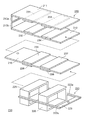
- FIG. 2 is an assembly diagram of the actuator 200 according to the present embodiment
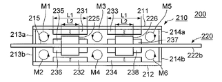
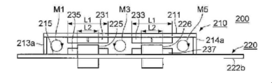
- FIG. 3 is a side view of the actuator 200 as viewed from the direction perpendicular to the paper surface of FIG. 1
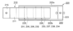
- FIG. 4 is a plan view of the actuator 200 as viewed obliquely from the lower left in FIG. It is.
- the term “axial direction” is used, and this “axial direction” means the horizontal direction in FIGS. 3 and 4.
- the actuator 200 has a housing part 210 and a coil holder 220.
- the casing unit 210 is a substantially rectangular parallelepiped casing surrounded by outer yokes 211 and 212 forming upper and lower walls and outer yokes 213a, 213b, 214a, and 214b forming front and rear walls.
- the outer yokes 211, 212, 213a, 213b, 214a, 214b are each formed of a rectangular flat magnetic material.
- the outer yokes 214a and 214b are not shown in order to prevent the drawing from becoming complicated.
- the outer yokes 211 and 212 are parallel to each other, and have flat portions facing each other at a predetermined interval.
- An inner yoke 215 made of a rectangular plate-like magnetic body is located in the center of the space between the flat portions of the outer yokes 211 and 212.
- the inner yoke 215 penetrates the gap between the outer yokes 213a and 213b from the outer side of the outer yokes 213a and 213b, and reaches the gap between the outer yokes 214a and 214b.
- the flat portions on the two front and back surfaces of the inner yoke 215 are opposed to the flat portions of the outer yokes 211 and 212.
- the ends of the inner yoke 215 protruding from the outer yokes 213a and 213b are fixed to the upper arm 301 in FIG. 1 by fixing means such as bolts (not shown).
- the coil holder 220 has two parallel rod portions 222a and 222b, coils 225 and 226, and a bridging portion 223.
- each of the coils 225 and 226 is a rectangular parallelepiped-shaped air core coil, and includes a rectangular parallelepiped hollow region (hollow space) penetrating in the axial direction.
- the coils 225 and 226 are fixed between the rod portions 222a and 222b at a predetermined interval in the axial direction.
- the inner yoke 215 passes through the hollow regions in the coils 225 and 226 of the coil holder 220.
- the coil holder 220 is movable in the axial direction along the inner yoke 215.
- the bridging portion 223 is fixed between the ends of the rod portions 222a and 222b, and is connected to the end portion of the connecting rod 299 in FIG.
- the actuator 200 has eight flat permanent magnets 231 to 238.
- the permanent magnets 231 and 233 are fixed to the outer yoke 211 with an interval in the axial direction and with the magnetic pole surface facing the inner yoke 215.
- the permanent magnets 232 and 234 are fixed to the outer yoke 212 with an interval in the axial direction and with the magnetic pole surface facing the inner yoke 215.
- the permanent magnets 235 and 237 are fixed to the inner yoke 215 with an interval in the axial direction and with the magnetic pole surface facing the outer yoke 211.
- the permanent magnets 236 and 238 are fixed to the inner yoke 215 with an interval in the axial direction and with the magnetic pole surface facing the outer yoke 212.
- the distance between the centers of the permanent magnets 231 and 233, the distance between the centers of the permanent magnets 232 and 234, the distance between the centers of the permanent magnets 235 and 237, the centers of the permanent magnets 236 and 238 The spacing between them is equal to the spacing between the centers of coils 225 and 226.
- the axial length L1 and the magnetic pole surface area of the permanent magnets 231 to 238 are equal to each other, and the axial length L2 and the number of turns of the coils 225 and 226 are also equal to each other.
- the axial length L1 of the permanent magnets 231 to 238 is longer than the axial length L2 of the coils 225 and 226.
- the permanent magnet 231 is S pole on the top, N pole on the bottom
- the permanent magnet 235 is S pole on the top, N pole on the bottom
- the permanent magnet 236 is N pole on the top, S pole on the bottom
- the permanent magnet 232 Is the north pole and the bottom is the south pole.
- the permanent magnet 233 has an N pole on the top, an S pole on the bottom
- the permanent magnet 237 has an N pole on the top, an S pole on the bottom
- the permanent magnet 238 has an S pole on the top, an N pole on the bottom
- the permanent magnet 234 has The top is the S pole and the bottom is the N pole.
- the direction of the magnetic poles of the permanent magnets is reversed between the outer yoke 211 side and the outer yoke 212 side of the inner yoke 215.
- the directions of the magnetic poles of the permanent magnets adjacent in the axial direction are opposite. Therefore, in the actuator 200, magnetic flux flows that pass through the following six different magnetic paths M1 to M6 are generated.
- First magnetic path M1 permanent magnet 231 ⁇ permanent magnet 235 ⁇ inner yoke 215 ⁇ outer yoke 213a ⁇ outer yoke 211 ⁇ permanent magnet 231
- second magnetic path M2 permanent magnet 232 ⁇ permanent magnet 236 ⁇ inner yoke 315 ⁇ outer yoke 213b ⁇ outer yoke 212 ⁇ permanent magnet 232
- third magnetic path M3 permanent magnet 231 ⁇ permanent magnet 235 ⁇ inner yoke 215 ⁇ permanent magnet 237 ⁇ permanent magnet 233 ⁇ outer yoke 211 ⁇ permanent magnet 231
- Fourth magnetic path M4 permanent magnet 232 ⁇ permanent magnet 236 ⁇ inner yoke 215 ⁇ permanent magnet 238 ⁇ permanent magnet 234 ⁇ outer yoke 211 ⁇ permanent magnet 232
- fifth magnetic path M5 permanent magnet 233 ⁇ outer yoke 211 ⁇ outer yoke 214a ⁇ inner yoke 215 ⁇ permanent magnet 237 ⁇ permanent
- the flat permanent magnets 231 to 238 generate an equal magnetic field between each of the flat outer yokes 211 and 212 and each of the flat inner yokes 215.
- the rectangular parallelepiped coils 225 and 226 are arranged in the magnetic field, it is possible to realize the actuator 200 that is lightweight and obtains a high driving force.
- the coils 225 and 226 are formed in a cylindrical shape like an existing speaker actuator.
- the magnetic circuit composed of the outer yoke, the inner yoke and the permanent magnet needs to be cylindrical, and a heavy magnetic material is required for this purpose.
- the rectangular parallelepiped coils 225 and 226 are employed as described above. Therefore, the permanent magnets 231 to 238, the outer yokes 211 and 212, and the inner yoke 215 constituting the magnetic circuit can all be formed into a flat plate shape, and the lightweight actuator 200 can be realized with a small amount of magnetic material.
- the coils 225 and 226 in the present embodiment have a flat rectangular parallelepiped shape having upper and lower flat portions facing the outer yokes 211 and 212 as shown in FIGS. For this reason, the total winding length of the coil windings in the plane portion perpendicular to the magnetic flux passing through the magnetic paths M1 to M6 and contributing to the generation of the driving force is It is longer than the line length and can generate a high driving force.
- the length L1 of the permanent magnets 231 to 238 in the axial direction is longer than the length L2 of the coils 225 and 226 in the axial direction. Therefore, when the coil 225 (226) is moved in the axial direction, the overlapping area of the coil 225 (226) and the permanent magnets 231, 235, 232, 236 (233, 237, 238, 234) is the same. In such a range, the relationship between the current flowing through the coil of the coil holder 220 and the force acting on the coil holder 220 can be kept linear.
- the magnetic paths M ⁇ b> 1 and M ⁇ b> 2 are provided in the left section in the figure among the sections obtained by dividing the housing portion 210 of the actuator 200 in the axial direction, and the magnetic path is provided in the middle section.
- the paths M3 and M4 have magnetic paths M5 and M6 in the right section. Therefore, each magnetic path length of the magnetic paths M1 to M6 can be shortened. Therefore, it is not necessary to increase the cross-sectional area of each of the magnetic paths M1 to M6 in order to reduce the magnetic resistance of each of the magnetic paths M1 to M6. Therefore, in this embodiment, the magnetic material can be reduced to reduce the weight of the actuator 200 in this sense.
- the driving force for the coil holding body 220 is generated by the two coils 225 and 226 arranged in the axial direction, a high driving force can be obtained.
- the actuator 200 that is lightweight, has a high driving force, and is capable of controlling the weakening force. Therefore, a robot capable of playing musical instruments can be realized by the actuator 200.
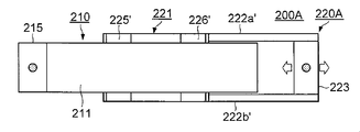
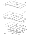
- FIG. 5 is an assembly view of the actuator 200A according to the second embodiment of the present invention
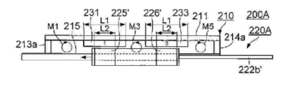
- FIG. 6 is a side view of the actuator 200A
- FIG. 7 is a plan view of the actuator 200A.
- This embodiment is different from the first embodiment (FIGS. 2 to 4) in the following points.
- the permanent magnets 235 to 238 are not fixed to the inner yoke 215.
- the coil holder 220 of the first embodiment is replaced with a coil holder 220A.
- the coil holding body 220A has a rectangular parallelepiped main body 221 including a hollow region penetrating in the longitudinal direction.
- the coil holding body 220A includes two rod portions 222a ′ and 222b ′ projecting in the longitudinal direction from two positions in the width direction at one end in the longitudinal direction of the main body 221, and ends of the rod portions 222a ′ and 222b ′. And a bridging portion 223 sandwiched between the portions.
- the bridging portion 223 is connected to the end of the connecting rod 299 in FIG.
- coils 225 ′ and 226 ′ are wound around each region near both ends in the longitudinal direction of the main body 221.
- the inner yoke 215 passes through a hollow region in the main body 221.
- the main body 221 is movable in the longitudinal direction along the inner yoke 215.
- FIG. 8 is a side view showing the coil holder 220A in a state where no coil is wound
- FIG. 9 is a plan view of the coil holder 220A.
- recesses 227 and 228 that make one round around the central axis of the main body 221 are formed at both ends in the longitudinal direction of the main body 221 of the coil holding body 220A.
- Coils 225 ′ and 226 ′ shown in FIGS. 5 to 7 are wound around the recesses 227 and 228, respectively.
- Other points are the same as in the first embodiment.
- the above is the configuration of the present embodiment.
- the same effect as the first embodiment can be obtained.
- the thickness between the flat portions of the coils 225 ′ and 226 ′ is reduced, and the area of the side surface of the coils 225 ′ and 226 ′ that does not contribute to the generation of the driving force. Can be reduced.
- the permanent magnets 235 to 238 are not provided, the distance between the outer yokes 211 and 212 and the inner yoke 215 can be shortened. Therefore, it is possible to realize an actuator that is thinner and lighter than the first embodiment and can provide a high driving force.
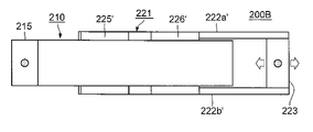
- FIG. 10 is a side view of an actuator 200B according to another embodiment of the present invention
- FIG. 11 is a plan view of the actuator 200B.
- the axial length L1 of the permanent magnet is longer than the axial length L2 of the coil.
- the present embodiment is a modification of the second embodiment, in which the axial length L2 of the coil is made longer than the axial length L1 of the permanent magnet.
- good linearity can be obtained in the axial range in which the areas of the overlapping regions of the permanent magnet and the coil are the same.
- two sets of permanent magnets and coils are arranged along the axial direction.
- one set or three or more sets of permanent magnets and coils may be arranged.
- a pair of permanent magnets and a pair of outer yokes are arranged with the inner yoke 215 interposed therebetween.
- a permanent magnet and an outer yoke may be arranged on one side of the inner yoke 215.
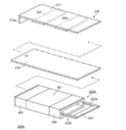
- 12 and 13 show an example in which the permanent magnet and the outer yoke on one side of the inner yoke 215 are omitted and the permanent magnet and the outer yoke are arranged only on the other side in the actuator 200 of the first embodiment. It is.
Landscapes
- Engineering & Computer Science (AREA)
- Power Engineering (AREA)
- Reciprocating, Oscillating Or Vibrating Motors (AREA)
- Manipulator (AREA)
Abstract
軽量であり、高い精度で駆動力を制御することができるアクチュエータが提供される。前記アクチュエータは、コイル配線により形成される平面部を有し、軸方向に貫通する中空空間を有するコイルと、前記コイルの平面部と対向する外側ヨークと、前記コイルの中空空間を貫通し、前記コイルの平面部と対向する内側ヨークと、前記内側ヨークに磁極を対向させて前記外側ヨークに固定され、前記コイル、前記内側ヨークおよび前記外側ヨークを含む磁路を通過する磁束を発生する平板状の外側永久磁石とを具備する。
Description
この発明は、アクチュエータに関し、特にロボットの可動部を駆動するアクチュエータに関する。この発明は、ロボット技術の分野において好ましく利用可能である。
ロボットやパワーアシスト装置等に関連した各種の分野において、可動部を駆動するための手段として、高精度な位置制御が可能な各種のアクチュエータが利用されている(特許文献1参照)。
しかしながら、楽器演奏をロボットに行わせるのに適したアクチュエータは未だ提供されていない。その理由は次の通りである。
まず、楽器演奏は音を出すのが目的であるので、それに使用するアクチュエータは、それ自身の動作音が極めて小さい必要がある。この条件があるため、楽器演奏に使用可能なアクチュエータの範囲がかなり絞られる。
また、人間らしい楽器演奏を行わせるためには、感度よく駆動力の制御を行うことが可能であり、かつ、脱力の制御も可能なアクチュエータが必要になる。例えば「太鼓をたたく」という動作の場合、実際に人間が太鼓をたたいている映像からバチの先端の軌跡を分析し、その動作をロボットアームで再現することはかなりの精度で可能であると考えられる。
しかし、そのようなバチの先端の位置制御を行うだけでは、人間が太鼓を叩いたような音は響かない。何故ならば、バチの軌跡は、すべてが人間の意思で動いているのではなく、多くの部分が太鼓側のリアクションによって作られているためである。バチの軌跡の最初の部分は、人間の意思で太鼓の皮に向かって力を込めてバチに運動エネルギーを与えることにより形成される。このとき筋肉は硬直した固いばねのような状態となる。このままの状態でバチが皮にあたるまでバチを振り続けると、音は出るものの、バチを皮に押し付けた状態になるので、皮の自由振動が妨げられる。このため、バチによる打撃音がミュートされ、太鼓特有の音の余韻が得られない。ロボットアームによる打撃もこれに近い状態になると考えられる。
実際の演奏では、バチに力を与えて加速したあと、皮にあたる直前に筋肉の力を抜く(脱力する)ことで、バチに運動エネルギーを与え、バチの先端を皮にぶつける。そうすることでバチの質量と皮のバネ性との間で連成共振を起こさせ、バチの運動エネルギーを効率よく皮の振動エネルギーに変えて音を発生させる。その後、演奏者は、バチが皮の反発力で跳ね返されたタイミングに合わせて筋肉に力を入れてバチを受け止める。この一連の動作の中で、人間の筋肉の力が関与しているのは最初の加速時と最後の静止時となる。音が出るタイミングの前後は、基本的に完全に脱力しているため、バチの動きはバチと太鼓の皮で決定されており、良い音を出すには筋肉がこの動きを妨げないようにすることが重要である。
このような脱力の制御をアクチュエータに行わせるためには、アクチュエータは、駆動(通電)していないときに無負荷(無抵抗)な状態とならなければならない。ここで、磁界中に置かれた導体のローレンツ力を利用する動電タイプのアクチュエータは、常時掛かる引力がなく、制動状態をコントロールすることができる。従って、この種のアクチュエータは、楽器演奏用のアクチュエータとして検討する余地がある。
この動電タイプのアクチュエータは、スピーカに使用されている。ここで、スピーカは、最終的に空気を振動させるものである。従って、スピーカにおいては、振動系(ムービング・コイル)の軽量化が最重要ファクタである。従って、スピーカでは、巨大な磁気回路と軽量なムービング・コイルとを組み合わせて大きな駆動力を得ることが多い。
しかしながら、ロボットには多数の筋肉を内蔵させる必要があり、それぞれの筋肉にスピーカのような巨大な磁気回路を持たせることはできない。また、スピーカのボイスコイルは円筒形である。このような円筒形のボイスコイルは、大きな変換効率が得られる点において有利である。しかし、ボイスコイルが円筒形であると、磁気ギャップもそれに合わせて円筒形にする必要があり、それには磁路形成のために鉄などの磁性体を多く使うことになる。このため、スピーカの磁気回路は非常に重いものになる。このため、スピーカに用いられている動電タイプのアクチュエータは、楽器演奏を行うロボット用のアクチュエータとして適切なものではなかった。
この発明は以上のような事情に鑑みてなされたものであり、軽量であり、高い精度で駆動力を制御することができるアクチュエータを提供することを目的としている。なお、この発明のアクチュエータは、楽器演奏を行うロボットを駆動するためのものとして好ましく使用可能であるが、その他の様々な用途にも使用可能である。
この発明の第1観点に係るアクチュエータは、コイル配線により形成される平面部を有し、軸方向に貫通する中空空間(中空領域)を有するコイルと、前記コイルの平面部と対向する外側ヨークと、前記コイルの中空空間を貫通し、前記コイルの平面部と対向する内側ヨークと、前記内側ヨークに磁極を対向させて前記外側ヨークに固定され、前記コイル、前記内側ヨークおよび前記外側ヨークを含む磁路を通過する磁束を発生する平板状の外側永久磁石とを具備する。
この発明の第2観点に係るアクチュエータは、第1観点に係るアクチュエータであって、前記外側ヨークとして、各々の間に前記コイルを挟むように配置される第1外側ヨーク及び第2外側ヨークを具備する。前記外側永久磁石として、前記第1外側ヨークに固定された第1外側永久磁石及び前記第2外側ヨークに固定された第2外側永久磁石からなる外側永久磁石対を具備する。前記第1外側永久磁石及び前記第2外側永久磁石は、各々の間に前記内側ヨークを挟むように配置され、同一極性の磁極を互いに対向させる。
この発明の第3観点に係るアクチュエータは、第2観点に係るアクチュエータであって、前記コイルとして、前記軸方向に沿って離間した第1コイル及び第2コイルを具備する。前記外側永久磁石として、複数の前記外側永久磁石対を具備する。前記複数の前記外側永久磁石対は、前記第1コイルと前記第2コイルとの間隔に対応した間隔で配置される。
この発明の第4観点に係るアクチュエータは、第1観点から第3観点のいずれかに係るアクチュエータであって、前記外側永久磁石の前記軸方向の長さと、前記コイルの前記軸方向の長さが異なる。
この発明の第5観点に係るアクチュエータは、第1観点から第4観点のいずれかに係るアクチュエータであって、前記外側ヨークに磁極を対向させて前記内側ヨークに固定され、前記コイル、前記内側ヨークおよび前記外側ヨークを含む磁路を通過する磁束を発生する平板状の内側永久磁石をさらに具備する。
この発明の第6観点に係るアクチュエータは、第5観点に係るアクチュエータであって、前記外側永久磁石及び前記内側永久磁石は、異なる極性の磁極を互いに対向させる。
この発明の第7観点に係るアクチュエータは、第5観点又は第6観点に係るアクチュエータであって、前記内側永久磁石として、第1内側永久磁石及び第2内側永久磁石からなる内側永久磁石対を具備する。前記第1内側永久磁石及び前記第2内側永久磁石は、各々の間に前記内側ヨークを挟むように配置される。
この発明の第8観点に係るアクチュエータは、第1観点から第7観点のいずれかに係るアクチュエータであって、前記外側ヨークは、平板状である。
この発明の第9観点に係るアクチュエータは、第1観点から第8観点のいずれかに係るアクチュエータであって、前記内側ヨークは、平板状である。
この発明の第10観点は、コイル配線が平面部をなし、軸方向に貫通する中空領域を有するコイルと、前記コイルの平面部と対向する外側ヨークと、前記コイルの中空領域を貫通し、前記コイルの平面部と対向する内側ヨークと、前記内側ヨークに磁極を対向させて前記外側ヨークに固定され、前記コイル、前記内側ヨークおよび前記外側ヨークを含む磁路を通過する磁束を発生する平板状の永久磁石とを具備することを特徴とするアクチュエータを提供する。
以下、図面を参照しつつ本発明の実施の形態について説明する。
<第1実施形態>
図1はこの発明の第1実施形態によるアクチュエータ200の適用例であるロボットアーム300を示す図である。このロボットアーム300は、ドラム演奏に用いられる。図1に示すように、ロボットアーム300は、上腕部301と、下腕部302とを有する。ここで、下腕部302の先端にはドラムスティック304が固定されている。上腕部301の先端には、関節303が設けられている。この関節303は、下腕部302のドラムスティック304と反対側の端部の近傍部分を貫通する軸(図示略)を備えている。下腕部302は、この関節303を支点として回動可能である。
図1はこの発明の第1実施形態によるアクチュエータ200の適用例であるロボットアーム300を示す図である。このロボットアーム300は、ドラム演奏に用いられる。図1に示すように、ロボットアーム300は、上腕部301と、下腕部302とを有する。ここで、下腕部302の先端にはドラムスティック304が固定されている。上腕部301の先端には、関節303が設けられている。この関節303は、下腕部302のドラムスティック304と反対側の端部の近傍部分を貫通する軸(図示略)を備えている。下腕部302は、この関節303を支点として回動可能である。
本実施形態によるアクチュエータ200は、上腕部301の下面に固定されている。下腕部302のドラムスティック304と反対側の端部は、連結棒299を介して、このアクチュエータ200のコイル保持体(図1では図示略)に連結されている。
図2は本実施形態によるアクチュエータ200の組み立て図、図3は同アクチュエータ200を図1の紙面垂直方向から見た側面図、図4は同アクチュエータ200を図1の左斜め下方から見た平面図である。なお、以下では、説明の便宜のため、「軸方向」という言葉を用いるが、この「軸方向」は図3および図4における左右方向を意味する。
図2~図4に示すように、アクチュエータ200は、筐体部210と、コイル保持体220とを有する。筐体部210は、上下の壁をなす外側ヨーク211および212と、前後の壁をなす外側ヨーク213a、213b、214a、214bとにより囲まれ、側方が吹き抜け状態の略直方体の筐体である。ここで、外側ヨーク211、212、213a、213b、214a、214bは、各々矩形平板状の磁性体により構成されている。なお、図2では、図面が煩雑になるのを防ぐため、外側ヨーク214a、214bの図示が省略されている。
外側ヨーク211および212は、互いに平行であり、所定間隔を空けて対向した平面部を各々有している。この外側ヨーク211および212の平面部間の空間の中央に矩形平板状の磁性体からなる内側ヨーク215が位置している。この内側ヨーク215は、外側ヨーク213a、213bの外側から外側ヨーク213aおよび213b間の隙間を貫通し、外側ヨーク214aおよび214b間の隙間に至っている。この内側ヨーク215の表裏2面の各平面部は、外側ヨーク211および212の各平面部に対向している。外側ヨーク213a、213bから突出した内側ヨーク215の端部は、図示しないボルト等の固定手段により図1の上腕部301に固定される。
コイル保持体220は、2本の平行な棒部222aおよび222bと、コイル225および226と、橋絡部223とを有する。ここで、コイル225および226は、各々直方体形状の空芯のコイルであり、軸方向に貫通する直方体形状の中空領域(中空空間)を内包している。このコイル225および226は、軸方向に所定間隔を空けて棒部222aおよび222b間に固定されている。そして、内側ヨーク215は、このコイル保持体220のコイル225および226内の中空領域を貫通している。コイル保持体220は、この内側ヨーク215に沿って軸方向に移動可能である。また、橋絡部223は、棒部222aおよび222bの先端間に固定されており、図1の連結棒299の端部に連結される。
コイル225および226において、外側ヨーク211に面した側には、外側ヨーク211に平行なコイル配線の束からなる平面部がある。また、コイル225および226において、外側ヨーク212に面した側にも、外側ヨーク212に平行なコイル配線の束からなる平面部がある。
図2~図4に示すように、アクチュエータ200は、8個の平板状の永久磁石231~238を有する。ここで、永久磁石231および233は、軸方向に間隔を空け、磁極面を内側ヨーク215に対向させて外側ヨーク211に固定されている。また、永久磁石232および234は、軸方向に間隔を空け、磁極面を内側ヨーク215に対向させて外側ヨーク212に固定されている。また、永久磁石235および237は、軸方向に間隔を空け、外側ヨーク211に磁極面を対向させて内側ヨーク215に固定されている。また、永久磁石236および238は、軸方向に間隔を空け、磁極面を外側ヨーク212に対向させて内側ヨーク215に固定されている。
図3および図4に示すように、永久磁石231および233の中心間の間隔、永久磁石232および234の中心間の間隔、永久磁石235および237の中心間の間隔、永久磁石236および238の中心間の間隔は、コイル225および226の中心間の間隔と等しい。また、永久磁石231~238の軸方向の長さL1および磁極表面積は互いに等しく、コイル225および226の軸方向の長さL2および巻回数も互いに等しい。そして、本実施形態では、永久磁石231~238の軸方向の長さL1は、コイル225および226の軸方向の長さL2よりも長い。
また、永久磁石231~234の各磁極の関係は次のようになっている。図3において、永久磁石231は上がS極、下がN極、永久磁石235は、上がS極、下がN極、永久磁石236は上がN極、下がS極、永久磁石232は、上がN極、下がS極である。また、永久磁石233は上がN極、下がS極、永久磁石237は、上がN極、下がS極、永久磁石238は上がS極、下がN極、永久磁石234は、上がS極、下がN極である。このように本実施形態では、軸方向の位置が同じである永久磁石に着目した場合、内側ヨーク215の外側ヨーク211側と外側ヨーク212側とで永久磁石の磁極の向きが逆向きになっており、内側ヨーク215の一方の側(例えば外側ヨーク211側)に着目した場合、軸方向に隣り合う永久磁石の磁極の向きが逆向きになっている。このため、アクチュエータ200では、次の6つの異なった磁路M1~M6を各々通過する磁束流が発生する。
第1の磁路M1:永久磁石231→永久磁石235→内側ヨーク215→外側ヨーク213a→外側ヨーク211→永久磁石231という磁路
第2の磁路M2:永久磁石232→永久磁石236→内側ヨーク215→外側ヨーク213b→外側ヨーク212→永久磁石232という磁路
第3の磁路M3:永久磁石231→永久磁石235→内側ヨーク215→永久磁石237→永久磁石233→外側ヨーク211→永久磁石231という磁路
第4の磁路M4:永久磁石232→永久磁石236→内側ヨーク215→永久磁石238→永久磁石234→外側ヨーク211→永久磁石232という磁路
第5の磁路M5:永久磁石233→外側ヨーク211→外側ヨーク214a→内側ヨーク215→永久磁石237→永久磁石233という磁路
第6の磁路M6:永久磁石234→外側ヨーク212→外側ヨーク214b→内側ヨーク215→永久磁石238→永久磁石234という磁路
以上が本実施形態の構成である。
第1の磁路M1:永久磁石231→永久磁石235→内側ヨーク215→外側ヨーク213a→外側ヨーク211→永久磁石231という磁路
第2の磁路M2:永久磁石232→永久磁石236→内側ヨーク215→外側ヨーク213b→外側ヨーク212→永久磁石232という磁路
第3の磁路M3:永久磁石231→永久磁石235→内側ヨーク215→永久磁石237→永久磁石233→外側ヨーク211→永久磁石231という磁路
第4の磁路M4:永久磁石232→永久磁石236→内側ヨーク215→永久磁石238→永久磁石234→外側ヨーク211→永久磁石232という磁路
第5の磁路M5:永久磁石233→外側ヨーク211→外側ヨーク214a→内側ヨーク215→永久磁石237→永久磁石233という磁路
第6の磁路M6:永久磁石234→外側ヨーク212→外側ヨーク214b→内側ヨーク215→永久磁石238→永久磁石234という磁路
以上が本実施形態の構成である。
本実施形態では、互いに逆向きの電流をコイル225および226に流すことにより、コイル保持体220に軸方向の力を発生させ、コイル保持体220を内側ヨーク215に沿って並進運動させることが可能である。コイル225および226に電流を流さない状態では、コイル225および226に駆動力は発生せず、脱力状態となる。
そして、本実施形態によれば、平板状の永久磁石231~238により、平板状の外側ヨーク211および212の各々と、平板状の内側ヨーク215との各間に、平等磁界が発生する。また、この磁界中に直方体形状のコイル225および226が配置されるため、軽量で高い駆動力の得られるアクチュエータ200を実現することができる。
仮に既存のスピーカ用のアクチュエータのようにコイル225および226を円筒形にしたとする。この場合、それに合わせて、外側ヨーク、内側ヨークおよび永久磁石からなる磁気回路を円筒形状にする必要があり、そのためには重量の大きな磁性材料が必要になる。
しかしながら、本実施形態では、上述のように直方体形状のコイル225および226が採用される。そのため、磁気回路を構成する永久磁石231~238、外側ヨーク211および212、内側ヨーク215を全て平板状とすることができ、少ない磁性材料により軽量のアクチュエータ200を実現することができる。
また、本実施形態におけるコイル225および226は、図2~図4に示すように外側ヨーク211および212と対向する上下の平面部を有する扁平な直方体形状をなしている。このため、磁路M1~M6を通過する磁束と直交し、駆動力の発生に寄与する平面部のコイル巻線の総巻線長が、平面部に垂直な側面部のコイル巻線の総巻線長よりも長く、高い駆動力を発生することができる。
また、本実施形態では、永久磁石231~238の軸方向の長さL1が、コイル225および226の軸方向の長さL2よりも長い。従って、コイル225(226)を軸方向に移動させた場合において、コイル225(226)と永久磁石231、235、232、236(233、237、238、234)との重複領域の面積が同一となる範囲において、コイル保持体220のコイルに流す電流とコイル保持体220に働く力との関係をリニアに保つことができる。
また、本実施形態では、図3に示すように、アクチュエータ200の筐体部210を軸方向に3分割した各区間のうち図中左側の区間に磁路M1およびM2が、真中の区間に磁路M3およびM4が、右側の区間に磁路M5およびM6が生じる。そのため、磁路M1~M6の各磁路長を短くすることができる。従って、各磁路M1~M6の磁気抵抗を下げるために、各磁路M1~M6の断面積を大きくする必要がない。従って、本実施形態では、この意味においても、磁性材料を少なくしてアクチュエータ200を軽量化することができる。
また、本実施形態では、軸方向に並んだ2個のコイル225および226によりコイル保持体220に対する駆動力を発生するので、高い駆動力を得ることができる。
以上のように、本実施形態によれば、軽量であり、かつ、高い駆動力が得られ、脱力の制御が可能なアクチュエータ200を実現することができる。従って、このアクチュエータ200により楽器演奏が可能なロボットを実現することができる。
<第2実施形態>
図5はこの発明の第2実施形態によるアクチュエータ200Aの組み立て図、図6は同アクチュエータ200Aの側面図、図7は同アクチュエータ200Aの平面図である。
図5はこの発明の第2実施形態によるアクチュエータ200Aの組み立て図、図6は同アクチュエータ200Aの側面図、図7は同アクチュエータ200Aの平面図である。
本実施形態は、次の点において上記第1実施形態(図2~図4)と異なる。まず、本実施形態では、内側ヨーク215に永久磁石235~238が固定されていない。また、本実施形態では、上記第1実施形態のコイル保持体220がコイル保持体220Aに置き換えられている。
コイル保持体220Aは、長手方向に貫通する中空領域を内包した直方体形状の本体221を有する。また、コイル保持体220Aは、この本体221の長手方向一端の幅方向両端の2箇所から長手方向に突き出した2本の棒部222a'および222b'と、この棒部222a'および222b'の端部間に挟まれた橋絡部223とをさらに有する。上記第1実施形態と同様、橋絡部223は、図1の連結棒299の端部に連結される。また、本体221の長手方向両端付近の各領域にはコイル225'および226'が巻回されている。内側ヨーク215は、この本体221内の中空領域を貫通している。本体221は、この内側ヨーク215に沿って長手方向に移動可能である。
図8はコイルが巻回されていない状態のコイル保持体220Aを示す側面図、図9は同コイル保持体220Aの平面図である。図示のようにコイル保持体220Aの本体221の長手方向両端には、本体221の中心軸廻りに1周する凹部227および228が形成されている。この凹部227および228に図5~図7のコイル225'および226'が巻回される。他の点は上記第1実施形態と同様である。
以上が本実施形態の構成である。
以上が本実施形態の構成である。
本実施形態においても上記第1実施形態と同様の効果が得られる。また、本実施形態によれば、永久磁石235~238がないため、コイル225'および226'の平面部間の厚みを減らし、駆動力の発生に寄与しないコイル225'および226'の側面の面積を減らすことができる。また、本実施形態によれば、永久磁石235~238がないため、外側ヨーク211および212と内側ヨーク215との間の距離を短くすることができる。従って、上記第1実施形態よりも薄型軽量であり、かつ、高い駆動力の得られるアクチュエータを実現することができる。
<他の実施形態>
以上、この発明の第1および第2実施形態について説明したが、この発明には他にも実施形態が考えられる。例えば次の通りである。
以上、この発明の第1および第2実施形態について説明したが、この発明には他にも実施形態が考えられる。例えば次の通りである。
(1)図10はこの発明の他の実施形態であるアクチュエータ200Bの側面図、図11は同アクチュエータ200Bの平面図である。上記第1および第2実施形態では、永久磁石の軸方向の長さL1をコイルの軸方向の長さL2よりも長くした。これに対し、本実施形態は、上記第2実施形態を変形したものであり、コイルの軸方向の長さL2を永久磁石の軸方向の長さL1をよりも長くしている。本実施形態においても、上記第1および第2実施形態と同様、永久磁石とコイルとの重複領域の面積が同一となる軸方向の範囲において、良好なリニアリティを得ることができる。
(2)上記各実施形態では、永久磁石およびコイルの組を軸方向に沿って2組配置したが、永久磁石およびコイルの組を1組あるいは3組以上配置してもよい。
(3)上記各実施形態では、内側ヨーク215を挟んで永久磁石の対、外側ヨークの対を配置した。しかしながら、図12~図15に示すように、内側ヨーク215の片側に永久磁石および外側ヨークを配置してもよい。なお、図12及び図13は、第1実施形態のアクチュエータ200において、内側ヨーク215の一方の側の永久磁石及び外側ヨークを省略し、もう一方の側にのみ永久磁石及び外側ヨークを配置した例である。また、図14及び図15は、第2実施形態のアクチュエータ200Aにおいて、内側ヨーク215の一方の側の永久磁石及び外側ヨークを省略し、もう一方の側にのみ永久磁石及び外側ヨークを配置した例である。
<特徴>
上記実施形態によれば、軽量であり、高い精度で駆動力を制御することができるアクチュエータを実現することができる。また、永久磁石の磁極と対向している平面部のコイル配線の電流がコイルに対する駆動力の発生に寄与する。従って、少ない磁性材料により構成される外側ヨーク、内側ヨークを用いて、軽量であり、高い精度で駆動力を制御することができるアクチュエータを実現することができる。
上記実施形態によれば、軽量であり、高い精度で駆動力を制御することができるアクチュエータを実現することができる。また、永久磁石の磁極と対向している平面部のコイル配線の電流がコイルに対する駆動力の発生に寄与する。従って、少ない磁性材料により構成される外側ヨーク、内側ヨークを用いて、軽量であり、高い精度で駆動力を制御することができるアクチュエータを実現することができる。
200,200A,200B……アクチュエータ、210……筐体、211,212,213a,213b,214a,214b……外側ヨーク、215……内側ヨーク、231~238……永久磁石、222a,222b,222a'、222b……棒部、225,226,225',226'……コイル、223……橋絡部、M1~M6……磁路、221……本体、227,228……凹部。
Claims (9)
- コイル配線により形成される平面部を有し、軸方向に貫通する中空空間を有するコイルと、
前記コイルの平面部と対向する外側ヨークと、
前記コイルの中空空間を貫通し、前記コイルの平面部と対向する内側ヨークと、
前記内側ヨークに磁極を対向させて前記外側ヨークに固定され、前記コイル、前記内側ヨークおよび前記外側ヨークを含む磁路を通過する磁束を発生する平板状の外側永久磁石とを具備する、アクチュエータ。 - 前記外側ヨークとして、各々の間に前記コイルを挟むように配置される第1外側ヨーク及び第2外側ヨークを具備し、
前記外側永久磁石として、前記第1外側ヨークに固定された第1外側永久磁石及び前記第2外側ヨークに固定された第2外側永久磁石からなる外側永久磁石対を具備し、
前記第1外側永久磁石及び前記第2外側永久磁石は、各々の間に前記内側ヨークを挟むように配置され、同一極性の磁極を互いに対向させる、請求項1に記載のアクチュエータ。 - 前記コイルとして、前記軸方向に沿って離間した第1コイル及び第2コイルを具備し、
前記外側永久磁石として、複数の前記外側永久磁石対を具備し、
前記複数の前記外側永久磁石対は、前記第1コイルと前記第2コイルとの間隔に対応した間隔で配置される、請求項2に記載のアクチュエータ。 - 前記外側永久磁石の前記軸方向の長さと、前記コイルの前記軸方向の長さが異なる、請求項1から3のいずれかに記載のアクチュエータ。
- 前記外側ヨークに磁極を対向させて前記内側ヨークに固定され、前記コイル、前記内側ヨークおよび前記外側ヨークを含む磁路を通過する磁束を発生する平板状の内側永久磁石
をさらに具備する、請求項1から4のいずれかに記載のアクチュエータ。 - 前記外側永久磁石及び前記内側永久磁石は、異なる極性の磁極を互いに対向させる、請求項5に記載のアクチュエータ。
- 前記内側永久磁石として、第1内側永久磁石及び第2内側永久磁石からなる内側永久磁石対を具備し、
前記第1内側永久磁石及び前記第2内側永久磁石は、各々の間に前記内側ヨークを挟むように配置される、請求項5または6に記載のアクチュエータ。 - 前記外側ヨークは、平板状である、請求項1から7のいずれかに記載のアクチュエータ。
- 前記内側ヨークは、平板状である、請求項1から8のいずれかに記載のアクチュエータ。
Applications Claiming Priority (2)
| Application Number | Priority Date | Filing Date | Title |
|---|---|---|---|
| JP2016-213848 | 2016-10-31 | ||
| JP2016213848A JP2018074816A (ja) | 2016-10-31 | 2016-10-31 | アクチュエータ |
Publications (1)
| Publication Number | Publication Date |
|---|---|
| WO2018079672A1 true WO2018079672A1 (ja) | 2018-05-03 |
Family
ID=62023664
Family Applications (1)
| Application Number | Title | Priority Date | Filing Date |
|---|---|---|---|
| PCT/JP2017/038748 Ceased WO2018079672A1 (ja) | 2016-10-31 | 2017-10-26 | アクチュエータ |
Country Status (2)
| Country | Link |
|---|---|
| JP (1) | JP2018074816A (ja) |
| WO (1) | WO2018079672A1 (ja) |
Cited By (1)
| Publication number | Priority date | Publication date | Assignee | Title |
|---|---|---|---|---|
| WO2026081534A1 (zh) * | 2024-10-15 | 2026-04-23 | 华为技术有限公司 | 一种电磁驱动机构、继电器、配电盒和配电系统 |
Citations (5)
| Publication number | Priority date | Publication date | Assignee | Title |
|---|---|---|---|---|
| JPS56129185U (ja) * | 1980-03-03 | 1981-10-01 | ||
| JPH0265645A (ja) * | 1988-08-30 | 1990-03-06 | Canon Inc | リニアモータ装置 |
| JPH0720083U (ja) * | 1993-09-08 | 1995-04-07 | 優一 森木 | 可動コイル形リニア直流モータ |
| JPH10112968A (ja) * | 1996-10-01 | 1998-04-28 | Yaskawa Electric Corp | ボイスコイルモータ |
| JP2000166211A (ja) * | 1998-11-20 | 2000-06-16 | Yaskawa Electric Corp | ボイスコイル形リニアモータ |
-
2016
- 2016-10-31 JP JP2016213848A patent/JP2018074816A/ja active Pending
-
2017
- 2017-10-26 WO PCT/JP2017/038748 patent/WO2018079672A1/ja not_active Ceased
Patent Citations (5)
| Publication number | Priority date | Publication date | Assignee | Title |
|---|---|---|---|---|
| JPS56129185U (ja) * | 1980-03-03 | 1981-10-01 | ||
| JPH0265645A (ja) * | 1988-08-30 | 1990-03-06 | Canon Inc | リニアモータ装置 |
| JPH0720083U (ja) * | 1993-09-08 | 1995-04-07 | 優一 森木 | 可動コイル形リニア直流モータ |
| JPH10112968A (ja) * | 1996-10-01 | 1998-04-28 | Yaskawa Electric Corp | ボイスコイルモータ |
| JP2000166211A (ja) * | 1998-11-20 | 2000-06-16 | Yaskawa Electric Corp | ボイスコイル形リニアモータ |
Cited By (1)
| Publication number | Priority date | Publication date | Assignee | Title |
|---|---|---|---|---|
| WO2026081534A1 (zh) * | 2024-10-15 | 2026-04-23 | 华为技术有限公司 | 一种电磁驱动机构、继电器、配电盒和配电系统 |
Also Published As
| Publication number | Publication date |
|---|---|
| JP2018074816A (ja) | 2018-05-10 |
Similar Documents
| Publication | Publication Date | Title |
|---|---|---|
| US11070119B2 (en) | Manufacturing method of vibrating actuator | |
| JP2015502737A (ja) | 小型線形振動触覚アクチュエータ | |
| US10784758B2 (en) | Linear vibration motor | |
| WO2017088359A1 (zh) | 线性振动马达 | |
| US11260526B2 (en) | Driving control apparatus for actuator | |
| JP2022524229A (ja) | 平衡振動システム | |
| CN115149767B (zh) | 电磁驱动可调刚度纳米定位平台 | |
| US11192141B2 (en) | Vibrating actuator | |
| JP2013541282A5 (ja) | ||
| JP5965451B2 (ja) | 高速ソレノイド | |
| WO2018079672A1 (ja) | アクチュエータ | |
| JP2020184841A (ja) | 振動アクチュエータ及び触覚デバイス | |
| US20100026120A1 (en) | Magnetic centre-finding device with no magnet on the rotor and with small air gap | |
| KR20030020787A (ko) | 기동자석형 vcm을 이용한 정밀 액츄에이터스테이지장치 | |
| JP2005198486A (ja) | 小型直動型アクチュエータ | |
| JPH1169754A (ja) | 永久磁石可動形リニア直流モータ | |
| JP2002051531A (ja) | 可動磁石式アクチュエータ | |
| JPWO2020027157A1 (ja) | リニア振動アクチュエータ | |
| JP2000262031A (ja) | ダンパ/発電装置 | |
| JPH0232749A (ja) | リニアアクチユエータ | |
| JP2021191013A (ja) | 振動アクチュエータ | |
| JP2021052449A (ja) | アクチュエータ及び触覚デバイス | |
| TAHARA et al. | Proposal and Control of a 2-DOF Spherical Actuator with Reduced Current Phase | |
| JPH10112967A (ja) | 単極形リニア直流モータ | |
| JP2020182911A (ja) | 振動アクチュエータ、振動アクチュエータユニット及び触覚デバイス |
Legal Events
| Date | Code | Title | Description |
|---|---|---|---|
| 121 | Ep: the epo has been informed by wipo that ep was designated in this application |
Ref document number: 17863472 Country of ref document: EP Kind code of ref document: A1 |
|
| NENP | Non-entry into the national phase |
Ref country code: DE |
|
| 122 | Ep: pct application non-entry in european phase |
Ref document number: 17863472 Country of ref document: EP Kind code of ref document: A1 |