WO2018079646A1 - 制御装置、制御システム、制御方法、及びプログラム - Google Patents
制御装置、制御システム、制御方法、及びプログラム Download PDFInfo
- Publication number
- WO2018079646A1 WO2018079646A1 PCT/JP2017/038672 JP2017038672W WO2018079646A1 WO 2018079646 A1 WO2018079646 A1 WO 2018079646A1 JP 2017038672 W JP2017038672 W JP 2017038672W WO 2018079646 A1 WO2018079646 A1 WO 2018079646A1
- Authority
- WO
- WIPO (PCT)
- Prior art keywords
- vehicle
- sound
- output
- control
- outside
- Prior art date
- Legal status (The legal status is an assumption and is not a legal conclusion. Google has not performed a legal analysis and makes no representation as to the accuracy of the status listed.)
- Ceased
Links
Images
Classifications
-
- B—PERFORMING OPERATIONS; TRANSPORTING
- B60—VEHICLES IN GENERAL
- B60W—CONJOINT CONTROL OF VEHICLE SUB-UNITS OF DIFFERENT TYPE OR DIFFERENT FUNCTION; CONTROL SYSTEMS SPECIALLY ADAPTED FOR HYBRID VEHICLES; ROAD VEHICLE DRIVE CONTROL SYSTEMS FOR PURPOSES NOT RELATED TO THE CONTROL OF A PARTICULAR SUB-UNIT
- B60W60/00—Drive control systems specially adapted for autonomous road vehicles
- B60W60/005—Handover processes
- B60W60/0053—Handover processes from vehicle to occupant
-
- B—PERFORMING OPERATIONS; TRANSPORTING
- B60—VEHICLES IN GENERAL
- B60R—VEHICLES, VEHICLE FITTINGS, OR VEHICLE PARTS, NOT OTHERWISE PROVIDED FOR
- B60R11/00—Arrangements for holding or mounting articles, not otherwise provided for
- B60R11/02—Arrangements for holding or mounting articles, not otherwise provided for for radio sets, television sets, telephones, or the like; Arrangement of controls thereof
-
- G—PHYSICS
- G08—SIGNALLING
- G08G—TRAFFIC CONTROL SYSTEMS
- G08G1/00—Traffic control systems for road vehicles
- G08G1/16—Anti-collision systems
-
- H—ELECTRICITY
- H04—ELECTRIC COMMUNICATION TECHNIQUE
- H04R—LOUDSPEAKERS, MICROPHONES, GRAMOPHONE PICK-UPS OR LIKE ACOUSTIC ELECTROMECHANICAL TRANSDUCERS; ELECTRIC HEARING AIDS; PUBLIC ADDRESS SYSTEMS
- H04R3/00—Circuits for transducers
-
- H—ELECTRICITY
- H04—ELECTRIC COMMUNICATION TECHNIQUE
- H04R—LOUDSPEAKERS, MICROPHONES, GRAMOPHONE PICK-UPS OR LIKE ACOUSTIC ELECTROMECHANICAL TRANSDUCERS; ELECTRIC HEARING AIDS; PUBLIC ADDRESS SYSTEMS
- H04R3/00—Circuits for transducers
- H04R3/04—Circuits for transducers for correcting frequency response
-
- B—PERFORMING OPERATIONS; TRANSPORTING
- B60—VEHICLES IN GENERAL
- B60K—ARRANGEMENT OR MOUNTING OF PROPULSION UNITS OR OF TRANSMISSIONS IN VEHICLES; ARRANGEMENT OR MOUNTING OF PLURAL DIVERSE PRIME-MOVERS IN VEHICLES; AUXILIARY DRIVES FOR VEHICLES; INSTRUMENTATION OR DASHBOARDS FOR VEHICLES; ARRANGEMENTS IN CONNECTION WITH COOLING, AIR INTAKE, GAS EXHAUST OR FUEL SUPPLY OF PROPULSION UNITS IN VEHICLES
- B60K28/00—Safety devices for propulsion-unit control, specially adapted for, or arranged in, vehicles, e.g. preventing fuel supply or ignition in the event of potentially dangerous conditions
- B60K28/10—Safety devices for propulsion-unit control, specially adapted for, or arranged in, vehicles, e.g. preventing fuel supply or ignition in the event of potentially dangerous conditions responsive to conditions relating to the vehicle
Definitions
- the present invention relates to a control device, a control system, a control method, and a program.
- a technology for calming the vehicle has been developed so that the volume of outside sound (sound generated outside the vehicle) that can be heard in the passenger compartment is reduced.
- outside sound is captured by an input device such as a microphone, and the outside sound is output from the output device such as a speaker to the inside of the vehicle so that the passengers in the vehicle can hear the outside sound.
- Patent Document 1 discloses a technique for suppressing the presentation of unnecessary audio information in the vehicle by presenting the sound generated by the sound outside the vehicle in the vehicle by a method according to the running state of the vehicle.
- the device according to Patent Document 1 detects the driver's line-of-sight direction, suppresses ambient sounds in the line-of-sight direction, and presents the vehicle exterior sound to the driver.
- Patent Document 2 discloses a technique for outputting a type of vehicle exterior sound designated by a user operation into the passenger compartment.
- JP 2009-258802 A Japanese Patent Laying-Open No. 2015-032155
- the present invention has been made in view of the above-described problems, and an object of the present invention is to provide a technique that allows the user to hear the sound outside the vehicle at a necessary timing in the vehicle interior.
- the invention according to claim 10 is: (1) an input device that captures an external sound generated outside the vehicle; and (2) an external sound captured by the input device is acquired, and the captured external sound is An output device for outputting the vehicle interior; (3) acquisition means for acquiring state information of the driver of the vehicle; and (4) capturing of the vehicle exterior sound by an input device capturing vehicle exterior sound generated outside the vehicle;
- the control system includes control means for controlling the output of the vehicle exterior sound by the output device that outputs the captured vehicle exterior sound to the interior of the vehicle based on the acquired state information.
- the invention according to claim 11 is a control method executed by a computer.
- the control method includes (1) an acquisition step of acquiring state information representing a state of a driver of the vehicle, and (2) capturing of the outside sound by the input device that captures outside sound generated outside the vehicle, or the capturing And a control step of controlling the output of the vehicle exterior sound by the output device that outputs the vehicle exterior sound to the vehicle interior based on the acquired state information.
- the invention described in claim 12 is a program for causing a computer to execute each step of the control method according to claim 8.
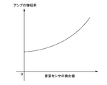
- FIG. 1 It is a figure which illustrates the control apparatus of Embodiment 1, and its use environment. It is a block diagram which illustrates a control device. It is a block diagram which illustrates the hardware constitutions of a control apparatus. 3 is a flowchart illustrating a flow of processing executed by the control device according to the first embodiment. It is a figure which illustrates the relationship between the detection value of a volume sensor, and the amplification factor of the amplifier of an output device in a graph format.
- each block in the block diagram represents a functional unit configuration, not a hardware unit configuration.
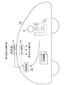
- FIG. 1 is a diagram illustrating a control device 200 according to the first embodiment and a use environment thereof.
- FIG. 1 is a diagram for facilitating understanding of the control apparatus 200, and does not limit the operation of the control apparatus 200.
- the vehicle 240 is an arbitrary vehicle such as an automobile or a train.
- the vehicle 240 may or may not have an automatic driving function.
- the input device 10 captures outside sound generated outside the vehicle 240.
- the input device 10 is configured using a microphone.
- the output device 20 acquires the vehicle exterior sound captured by the input device 10 and outputs the vehicle exterior sound to the interior of the vehicle 240.
- the output device 20 is configured using a speaker.
- the control device 200 controls the output of the vehicle exterior sound to the vehicle interior by controlling the input device 10 or the output device 20. At that time, the control device 200 uses state information indicating the state of the driver 40 that is the driver of the vehicle 240. Details of the state information will be described later.
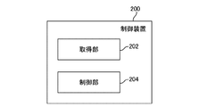
- FIG. 2 is a block diagram illustrating the control device 200.
- the control device 200 includes an acquisition unit 202 and a control unit 204.
- the acquisition unit 202 acquires state information of the driver 40. Based on the acquired state information, the control unit 204 controls capturing of the vehicle exterior sound by the input device 10 or output of the vehicle exterior sound by the output device 20. Note that the control unit 204 may control both the input device 10 and the output device 20, or may control only one of them.
- the outside sound heard by the driver 40 in the vehicle interior is controlled by the control based on the state of the driver 40.
- the driver 40 can hear the sound outside the vehicle at a timing when the state of the driver 40 needs to hear the sound outside the vehicle.
- control device 200 controls the input device 10 and the output device 20 when the concentration of the driver 40 is reduced, or when the driver 40 is drowsy or fatigued, and causes the driver 40 to hear the sound outside the vehicle. Let me hear. By doing so, it is possible to awaken the driver 40 using the sound outside the vehicle, and it is possible to prevent an accident from occurring.
- control device 200 of the present embodiment will be described in more detail.
- Each functional component of the control device 200 may be realized by hardware (eg, a hard-wired electronic circuit) that implements each functional component, or a combination of hardware and software (eg, electronic A combination of a circuit and a program for controlling the circuit may be realized.
- hardware eg, a hard-wired electronic circuit
- software eg, electronic A combination of a circuit and a program for controlling the circuit may be realized.
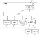
- FIG. 3 is a diagram illustrating a hardware configuration of the control device 200.
- the computer 100 is a computer that implements the control device 200.
- the computer 100 is a ECU (Electronic Control Unit) that controls various hardware provided in the vehicle 240.
- the computer 100 may be a computer designed exclusively for realizing the control device 200, or may be a general-purpose computer.
- the computer 100 includes a bus 102, a processor 104, a memory 106, a storage device 108, an input / output interface 110, and a network interface 112.
- the bus 102 is a data transmission path through which the processor 104, the memory 106, the storage device 108, the input / output interface 110, and the network interface 112 transmit / receive data to / from each other.
- the method of connecting the processors 104 and the like is not limited to bus connection.
- the processor 104 is an arithmetic processing device realized using a microprocessor or the like.
- the memory 106 is a main storage device realized using a RAM (Random Access Memory) or the like.
- the storage device 108 is an auxiliary storage device realized using a ROM (Read Only Memory), a flash memory, or the like.
- the storage device 108 may be configured by hardware similar to the hardware configuring the main storage device such as a RAM.
- the input / output interface 110 is an interface for connecting the computer 100 to peripheral devices.
- a microphone 12 that realizes the input device 10 and a speaker 22 that realizes the output device 20 are connected to the input / output interface 110.
- Various analog signals and digital signals used for controlling the vehicle 240 are input or output to the computer 100 via the input / output interface 110.
- an audio signal representing outside-vehicle sound captured by the input device 10 is input from the input device 10 to the computer 100 via the input / output interface 110.
- an audio signal to be output from the output device 20 is output from the computer 100 to the output device 20 via the input / output interface 110.
- the input / output interface 110 appropriately includes an A / D converter that converts an analog input signal into a digital signal, a D / A converter that converts a digital output signal into an analog signal, and the like.
- the network interface 112 is an interface for connecting the computer 100 to a communication network.
- This communication network is, for example, a CAN (Controller Area Network) communication network.
- the method of connecting the network interface 112 to the communication network may be a wireless connection or a wired connection.
- the storage device 108 stores a program module for realizing each functional component of the control device 200.
- the processor 104 reads out the program module to the memory 106 and executes it, thereby realizing the function of the control device 200.
- the input device 10 is an arbitrary device that can capture the outside sound of the vehicle 240.
- the input device 10 is configured using the microphone 12 described above.
- the output device 20 is an arbitrary device that can output the sound captured by the vehicle 240 to the interior of the vehicle 240.
- the output device 20 is configured using the speaker 22 described above.
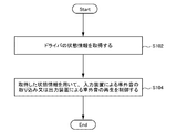
- FIG. 4 is a flowchart illustrating the flow of processing executed by the control device 200 according to the first embodiment.
- the acquisition unit 202 acquires state information of the driver 40 (S102).
- the control unit 204 uses the state information of the driver 40 to control the capturing of the outside sound by the input device 10 or the output of the outside sound by the output device 20 (S104).
- the acquisition unit 202 acquires the status information of the driver 40 (S102).
- the state information is information indicating an index value indicating, for example, the height of concentration of the driver 40, the amount of sleepiness, or the degree of fatigue.
- These index values can be calculated by analyzing a captured image captured by the driver 40, for example. More specifically, it can be calculated based on the movement of the eyeball of the driver 40 included in the captured image, the number of blinks, or the number of yawns.
- an existing technique can be used as a technique for estimating a person's high concentration, sleepiness, or fatigue level using an image of the person.
- the method of calculating an index value representing the height of concentration of the driver 40, the amount of sleepiness, the degree of fatigue, etc. is not limited to the method of using a captured image including the driver 40.
- these index values may be calculated using the biological information of the driver 40.
- the biological information is the blood flow, the pulse rate, the heart rate, or the body temperature of the driver 40.
- the state information may represent these pieces of biological information as they are, or may indicate the level of concentration of the driver 40, the amount of sleepiness, or the degree of fatigue calculated based on these pieces of biological information. Also good.
- An existing technique can be used as a technique for estimating a person's level of concentration, drowsiness, or degree of fatigue based on a person's biological information.
- the generation of the status information may be performed by the control device 200 or may be performed by a device other than the control device 200. In the former case, the control device 200 acquires the above-described captured image and biological information and generates state information.
- control device 200 acquires the generated state information from a device that acquires the above-described captured image and biological information and generates state information.
- the device that generates the state information is, for example, a server machine that is communicably connected to the control device 200.
- a camera that captures the driver 40 and generates the captured image is installed in the vehicle 240.
- This camera may be a still camera that captures still images or a video camera that captures moving images.
- Devices that generate state information (including the control device 200) acquire captured images generated by these cameras.
- a sensor such as a blood flow sensor or a heart rate sensor
- the apparatus that generates the state information acquires the measurement result of the sensor.
- the senor is installed on the handle or seat of the vehicle 240.
- a sensor installed in the seat for example, there is a sensor that grasps the heart rate of the driver 40 by measuring the response of the driver 40 when a weak current is passed through the seat.
- the sensor may be provided in a wearable terminal attached to the driver 40.
- the control unit 204 controls the input device 10 or the output device 20 based on the state information (S104). For example, the control unit 204 performs control for awakening the driver 40 when the concentration of the driver 40 is low, or when the driver 40 is drowsy or fatigued. On the other hand, when the concentration of the driver 40 is not low, or when the drowsiness or fatigue level of the driver 40 is not large, the control unit 204 performs control other than the control for awakening the driver 40 (for example, for awakening the driver 40). Control to stop control).
- specific examples of control will be described in the order of a method for controlling the output device 20 and a method for controlling the input device 10.
- Control Method 1 of Output Device 20 Based on the state information, the control unit 204 determines whether to cause the output device 20 to output a sound outside the vehicle. In the case where the state information represents the high concentration power of the driver 40, the control unit 204 causes the output device 20 to output an external sound when the high concentration power of the driver 40 is a predetermined value or less. On the other hand, if the concentration of the driver 40 is greater than a predetermined value, the control unit 204 does not cause the output device 20 to output outside sound.
- the control unit 204 causes the output device 20 to output a sound outside the vehicle when the magnitude of sleepiness of the driver 40 is a predetermined value or more.
- the control unit 204 does not cause the output device 20 to output a sound outside the vehicle. Similar control is performed even in the case where the state information represents the degree of fatigue of the driver 40.
- the predetermined values may be set in advance in the control unit 204 or may be stored in a storage device accessible from the control unit 204.
- control unit 204 When outputting the vehicle exterior sound to the output device 20, for example, the control unit 204 performs control to turn on the switch of the output device 20. On the other hand, when the output device 20 does not output outside vehicle sound, for example, the control unit 204 performs control to turn off the switch of the output device 20.
- the control device 200 awakens the driver 40 by intentionally letting the driver 40 hear a sound outside the vehicle when the concentration of the driver 40 is low, or when drowsiness or fatigue is high.
- the concentration of the driver 40 is not low and when the sleepiness or fatigue level of the driver 40 is not high, the driver 40 is prevented from getting used to the outside sound by preventing the driver 40 from listening to the outside sound. .
- Control Method 2 of Output Device 20 ⁇ Control Method 2 of Output Device 20 >>
- the output device 20 is provided with an audio filter.
- the control unit 204 determines whether or not to apply the audio filter to the vehicle exterior sound output from the output device 20.
- an audio filter is a filter that cuts sound in a specific frequency region. More specifically, for example, the audio filter is a filter that cuts a sound that the driver 40 feels uncomfortable. The sound that the driver 40 feels uncomfortable is a brake sound of a large vehicle such as a dump truck.
- the control unit 204 filters the sound outside the vehicle output from the output device 20 when the high concentration power of the driver 40 is a predetermined value or less. Does not apply. On the other hand, when the height of the concentration of the driver 40 is greater than a predetermined value, the control unit 204 applies an audio filter to the vehicle exterior sound output from the output device 20.
- the control unit 204 applies an audio filter to the outside sound output from the output device 20 when the magnitude of the sleepiness of the driver 40 is equal to or greater than a predetermined value. do not do.
- the control unit 204 applies an audio filter to the vehicle exterior sound output from the output device 20. Similar control is performed even in the case where the state information represents the degree of fatigue of the driver 40.
- the predetermined values may be set in advance in the control unit 204 or may be stored in a storage device accessible from the control unit 204.
- the control unit 204 controls the switch circuit of the output device 20 so that a signal representing the outside sound passes through the sound filter.
- the control unit 204 controls the switch circuit included in the output device 20 so that a signal representing the outside sound does not pass through the sound filter.
- the control device 200 lets the driver 40 hear a sound outside the vehicle to which the audio filter is not applied. In this way, for example, an unpleasant sound such as a brake sound of a large vehicle is intentionally heard by the driver 40 and the driver 40 is awakened.
- the concentration of the driver 40 is not low or when the drowsiness or fatigue level of the driver 40 is not large, the driver 40 is accustomed to the outside sound by preventing the driver 40 from listening to the outside sound. prevent.
- the control unit 204 may realize the same thing as when the output device 20 is controlled by controlling the input device 10 similarly to the output device 20. For example, the control unit 204 determines whether or not the input device 10 captures the outside sound, instead of determining whether or not the output device 20 outputs the outside sound. Specifically, the control unit 204 does not cause the input device 10 to capture the vehicle exterior sound in each case described above in which the output device 20 does not output the vehicle exterior sound. On the other hand, the control unit 204 causes the input device 10 to capture the external sound in each of the cases described above that causes the output device 20 to output the external sound. By doing so, the same effect as the method of controlling the output of the vehicle exterior sound by the output device 20 can be obtained.
- the control unit 204 determines whether or not to apply the sound filter to the sound outside the vehicle captured by the input device 10. It may be controlled.
- the above-described audio filter is provided in the input device 10.
- the control unit 204 applies the sound filter to the vehicle exterior sound captured by the input device 10 in each of the cases described above where the speech filter is applied to the vehicle exterior sound output from the output device 20.
- the control unit 204 does not apply the audio filter to the vehicle exterior sound captured by the input device 10 in each of the above cases where the speech filter is not applied to the vehicle exterior sound output from the output device 20. By doing so, it is possible to obtain the same effect as the method for controlling the application of the audio filter to the outside sound output from the output device 20.
- the control unit 204 may adjust the loudness of the vehicle exterior sound using the state information. For example, the control unit 204 performs control to relatively reduce the volume of the vehicle exterior sound output from the output device 20 instead of the control not to output the vehicle exterior sound to the output device 20. Similarly, the control unit 204 performs control for relatively increasing the volume of the vehicle exterior sound output from the output device 20 instead of the control for causing the output device 20 to output the vehicle exterior sound. Control of the loudness of the vehicle exterior sound output to the output device 20 can be realized, for example, by controlling the amplification factor of the amplifier included in the output device 20.
- control unit 204 performs control to relatively reduce the magnitude of the vehicle exterior sound captured by the input device 10 instead of the control that does not capture the vehicle exterior sound in the input device 10.
- control unit 204 performs control to relatively increase the magnitude of the vehicle exterior sound captured from the input device 10 instead of the control that causes the input device 10 to capture the vehicle exterior sound.
- the control of the magnitude of the outside sound taken in by the input device 10 can be realized by controlling the sensitivity of a microphone included in the input device 10, for example.
- the control unit 204 controls the input device 10 and the output device 20 to wake up the driver 40, and when a predetermined condition is satisfied, the control unit 204 controls the input device 10 and the output device 20 that are controlled to wake up the driver 40. It is preferable to change the state. By doing so, it is possible to prevent the driver 40 from getting used to the sound outside the vehicle.
- the control unit 204 changes the state of the input device 10 or the output device 20 when a predetermined time elapses after controlling the input device 10 or the output device 20 to wake up the driver 40, for example. For example, in the case where control is performed so that a sound outside the vehicle is output from the output device 20 in order to wake the driver 40, the control unit 204 does not output a sound outside the vehicle from the output device 20 after a predetermined time has elapsed since the control. Like that.
- control unit 204 changes the state of the input device 10 or the output device 20 when the vehicle 240 travels a predetermined distance after controlling the input device 10 or the output device 20 to wake up the driver 40. May be.
- the timing at which the control device 200 executes the series of processes shown in FIG. 4 is arbitrary.
- the control device 200 executes a series of processes shown in FIG. 4 at a predetermined cycle.
- the predetermined period may be set in advance in the control device 200 or may be stored in a storage device accessible from the control device 200.
- the series of processing illustrated in FIG. 4 is performed. May be executed.
- the control device 200 performs the series of processes described above at the timing when the driver 40 is approaching the place where the driver 40 should be awakened. In this case, a location requiring attention is set in advance in the map information.
- Embodiment 2 The control apparatus 200 of Embodiment 2 is represented by FIG. 1 like the control apparatus 200 of Embodiment 1, for example. Except for the items described below, the control device 200 of the second embodiment is the same as the control device 200 of the first embodiment.
- the control unit 204 determines the magnitude of the reproduced outside vehicle sound based on the volume of the sound generated in the room of the vehicle 240 when the outside sound is reproduced in the room of the vehicle 240.
- the loudness of the room in the vehicle 240 is detected using a volume sensor provided in the room of the vehicle 240, for example.
- control unit 204 controls the input device 10 and the output device 20 so that the loudness of the vehicle interior is increased as the loudness of the vehicle 240 is increased. Control the set value. For example, the control unit 204 increases the reproduction volume of the output device 20 by setting the amplification factor of the amplifier included in the output device 20 to a higher value as the loudness of the room in the vehicle 240 increases.
- control unit 204 sets the sensitivity of the microphone included in the input device 10 to a higher value as the loudness of the room in the vehicle 240 is larger, so that the outside sound captured by the input device 10 is increased. Increase the size.
- control unit 204 sets the sensitivity of the sound filter provided in the input device 10 or the output device 20 to a lower value as the volume of the sound in the room of the vehicle 240 is larger, so that the input device 10
- the magnitude of a predetermined type of vehicle exterior sound (for example, a brake sound of a large vehicle) captured by the output device 20 or the magnitude of a predetermined type vehicle exterior sound output by the output device 20 is increased.
- FIG. 5 is a graph illustrating the relationship between the detection value of the volume sensor and the amplification factor of the amplifier of the output device 20 in a graph format.
- the control unit 204 acquires a detection value from the volume sensor. Then, the control unit 204 sets the amplification factor of the amplifier of the output device 20 to a value corresponding to the acquired detection value.
- the hardware configuration of the control device 200 according to the second embodiment is represented in FIG. 3, for example, similarly to the hardware configuration of the control device 200 according to the first embodiment.
- the program module stored in the storage device 108 further includes a program that implements the functions described in the present embodiment.
- the magnitude of the outside vehicle sound reproduced in the room of the vehicle 240 is determined based on the magnitude of the sound generated in the room of the vehicle 240. By doing so, the driver 40 can reliably hear the sound outside the vehicle.
- control device 200 can include the functions of the following modified examples in addition to or instead of the functions of the above-described embodiments.
- the vehicle 240 has an automatic driving function.
- a driving authority may be transferred from the system to a person, that is, switching from automatic driving to manual driving may occur.
- the control unit 204 causes the output device 20 to output a sound when the vehicle 240 is switched from automatic operation to manual operation. At this time, the control unit 204 acquires information indicating a time point at which switching from automatic operation to manual operation is performed (hereinafter referred to as “switching time point”). Then, the control unit 204 causes the output device 20 to output sound at a time before the switching time. In this way, the driver 40 is notified that the automatic operation is switched to the manual operation.
- the control unit 204 may control the sound output from the output device 20 in accordance with the emergency degree of the switching. For example, in the case of switching with a high degree of urgency (when it is necessary to immediately switch to manual operation), the control unit 204 causes the output device 20 to output an alarm sound instead of a vehicle exterior sound. On the other hand, in the case of switching with a low degree of urgency (when it is not necessary to immediately switch to manual operation), the control unit 204 causes the output device 20 to output sound outside the vehicle.
- an index value representing the emergency degree is set in advance for each cause (event) that requires switching from automatic driving to manual driving.
- the control unit 204 acquires an index value representing the urgent degree of switching together with the switching time described above. When the acquired index value is greater than or equal to the predetermined value, the control unit 204 causes the output device 20 to output an alarm sound. On the other hand, when the index value is less than the predetermined value, the control unit 204 causes the output device 20 to output a sound outside the vehicle.
- the control unit 204 outputs the signal before the switch to manual operation occurs (for example, after 30 seconds have passed after the hand is released from the handle) because the passenger has released the hand from the handle.
- a sound outside the vehicle may be output from the device 20.
- an alarm sound is output from the output device 20 to warn that a switch from automatic operation to manual operation occurs after a predetermined time, and then an external sound is output from the output device 20 at the timing when the actual switch occurs.
- the control unit 204 may determine the timing (hereinafter, “output time point”) for outputting the vehicle exterior sound from the output device 20 at the time of the above switching, using the state information. Specifically, the control unit 204 outputs an output time point when the concentration of the driver 40 is low or when the sleepiness or fatigue level of the driver 40 is large, when the concentration of the driver 40 is high, Make it faster than the output time when the degree of fatigue is small. In this way, the driver 40 is awakened early in a situation where the driver 40 is considered to be relatively difficult to notice sounds outside the vehicle (when the concentration of the driver 40 is low or when the driver 40 is drowsy or tired). Thus, the driver 40 can start manual operation with a margin.
- a second predetermined value used in the case is determined in advance. The first predetermined value is larger than the second predetermined value.
- the control unit 204 sets a value obtained by subtracting the first predetermined value from the switching time as the output time.
- the concentration of the driver 40 is high, or when the drowsiness or fatigue level of the driver 40 is small
- the control unit 204 sets a value obtained by subtracting the second predetermined value from the switching time as the output time.
- control unit 204 may gradually increase the volume of the outside sound output from the output device 20 when the concentration of the driver 40 is low, or when the sleepiness or fatigue level of the driver 40 is large. By doing so, it is possible to prevent the driver 40 from being surprised by suddenly letting the driver 40 in a bad state hear a sound outside the vehicle, such as when the concentration is reduced.
- the method for controlling the volume of the external sound is not limited to the method described above.
- the control unit 204 when the concentration of the driver 40 is low, or when the driver 40 is drowsy or tired, the control unit 204 outputs a sound outside the vehicle at a volume higher than normal, and then gradually decreases the volume to The volume may be set to. By doing so, the driver 40 in a bad state can be awakened by a loud outside sound.
Landscapes
- Engineering & Computer Science (AREA)
- Physics & Mathematics (AREA)
- Acoustics & Sound (AREA)
- Signal Processing (AREA)
- Mechanical Engineering (AREA)
- General Physics & Mathematics (AREA)
- Automation & Control Theory (AREA)
- Human Computer Interaction (AREA)
- Transportation (AREA)
- Traffic Control Systems (AREA)
Abstract
制御装置(200)は、車両(240)のドライバであるドライバ(40)の状態を表す状態情報に基づいて、入力装置(10)による車外音の取り込み、又は出力装置(20)による車外音の出力を制御する。こうすることで、車両(240)の室内に対する車外音の出力を制御する。入力装置(10)は、車両(240)の外部で発生する車外音を取り込む。出力装置(20)は、入力装置(10)によって取り込まれた車外音を取得し、その車外音を車両(240)の室内に出力する。
Description
本発明は、制御装置、制御システム、制御方法、及びプログラムに関する。
自動車などの車両において、車室内で聞こえる車外音(車両の外で発生した音)の大きさが小さくなるように、車両を静穏化する技術が開発されている。一方で、車外音は危険察知などの目的で必要なケースもある。そこで、車外音をマイクなどの入力装置で取り込み、その車外音をスピーカなどの出力装置から車内に出力することで、車外音を車内の乗員に聞かせる技術が開発されている。
例えば特許文献1は、車外音で発生した音を車両の走行状態に応じた方法で車内に提示することで、車内における不要な音声情報の提示を抑制する技術を開示している。例えば特許文献1に係る装置は、ドライバの視線方向を検出し、視線方向の周囲音について抑圧して車外音をドライバに提示する。
その他にも例えば、特許文献2は、ユーザ操作によって指定された種別の車外音を車室内に出力する技術を開示している。
前述したように、車外音は危険察知などの目的で必要なことがある。一方で、常に車外音が聞こえるとドライバは車外音に慣れてしまうため、車外音から危険を察知しづらくなってしまう。特許文献1や特許文献2はこの問題については言及していない。
本発明は、上述の課題鑑みてなされたものであり、車室内において必要なタイミングで車外音を聞けるようにする技術を提供することを一つの目的とする。
請求項1に記載の発明は、(1)車両のドライバの状態を表す状態情報を取得する取得手段と、(2)前記車両の外で発生した車外音を取り込む入力装置による前記車外音の取り込み、又は前記取り込まれた車外音を前記車両の室内に出力する出力装置による前記車外音の出力を、前記取得した状態情報に基づいて制御する制御手段と、を有する制御装置である。
請求項10に記載の発明は、(1)車両の外部で発生する車外音を取り込む入力装置と、(2)前記入力装置によって取り込まれた車外音を取得し、前記取り込まれた車外音を前記車両の室内に出力する出力装置と、(3)前記車両のドライバの状態情報を取得する取得手段と、(4)前記車両の外で発生した車外音を取り込む入力装置による前記車外音の取り込み、又は前記取り込まれた車外音を前記車両の室内に出力する出力装置による前記車外音の出力を、前記取得した状態情報に基づいて制御する制御手段と、を有する制御システムである。
請求項11に記載の発明は、コンピュータによって実行される制御方法である。
当該制御方法は、(1)車両のドライバの状態を表す状態情報を取得する取得ステップと、(2)前記車両の外で発生した車外音を取り込む入力装置による前記車外音の取り込み、又は前記取り込まれた車外音を前記車両の室内に出力する出力装置による前記車外音の出力を、前記取得した状態情報に基づいて制御する制御ステップと、を有する。
当該制御方法は、(1)車両のドライバの状態を表す状態情報を取得する取得ステップと、(2)前記車両の外で発生した車外音を取り込む入力装置による前記車外音の取り込み、又は前記取り込まれた車外音を前記車両の室内に出力する出力装置による前記車外音の出力を、前記取得した状態情報に基づいて制御する制御ステップと、を有する。
請求項12に記載の発明は、請求項8に記載の制御方法の各ステップをコンピュータに実行させるプログラムである。
上述した目的、およびその他の目的、特徴および利点は、以下に述べる好適な実施の形態、およびそれに付随する以下の図面によってさらに明らかになる。
以下、本発明の実施の形態について、図面を用いて説明する。尚、すべての図面において、同様な構成要素には同様の符号を付し、適宜説明を省略する。また、特に説明する場合を除き、ブロック図における各ブロックは、ハードウエア単位の構成ではなく、機能単位の構成を表している。
図1は、実施形態1の制御装置200及びその使用環境を例示する図である。なお、図1は制御装置200に関する理解を容易にするための図であり、制御装置200の動作を何ら限定するものではない。
車両240は、自動車や電車などの任意の車両である。車両240は、自動運転機能を有していてもよいし、有していなくてもよい。入力装置10は、車両240の外部で発生する車外音を取り込む。例えば入力装置10はマイクを用いて構成される。出力装置20は、入力装置10によって取り込まれた車外音を取得し、その車外音を車両240の室内に出力する。例えば出力装置20はスピーカを用いて構成される。
制御装置200は、入力装置10又は出力装置20を制御することで、上記車両の室内に対する車外音の出力を制御する。その際、制御装置200は、車両240のドライバであるドライバ40の状態を表す状態情報を利用する。状態情報の詳細については後述する。
図2は、制御装置200を例示するブロック図である。制御装置200は、取得部202及び制御部204を有する。取得部202は、ドライバ40の状態情報を取得する。制御部204は、取得した状態情報に基づいて、入力装置10による車外音の取り込み、又は出力装置20による車外音の出力を制御する。なお、制御部204は、入力装置10及び出力装置20の双方を制御してもよいし、いずれか一方のみを制御してもよい。
本実施形態の制御装置200によれば、ドライバ40の状態に基づく制御により、ドライバ40が車室内で聞く車外音が制御される。これにより、ドライバ40の状態が車外音を聞く必要があるタイミングで、ドライバ40に車外音を聞かせることができる。
例えば制御装置200は、ドライバ40の集中力が下がっている場合や、ドライバ40の眠気や疲労度が大きくなっている場合に、入力装置10や出力装置20を制御して、ドライバ40に車外音を聞かせる。こうすることで、車外音を利用してドライバ40を覚醒させることができ、事故の発生などを未然に防ぐことができる。
以下、本実施形態の制御装置200について、さらに詳細に説明する。
<制御装置200のハードウエア構成の例>
制御装置200の各機能構成部は、各機能構成部を実現するハードウエア(例:ハードワイヤードされた電子回路など)で実現されてもよいし、ハードウエアとソフトウエアとの組み合わせ(例:電子回路とそれを制御するプログラムの組み合わせなど)で実現されてもよい。以下、制御装置200の各機能構成部がハードウエアとソフトウエアとの組み合わせで実現される場合について、さらに説明する。
制御装置200の各機能構成部は、各機能構成部を実現するハードウエア(例:ハードワイヤードされた電子回路など)で実現されてもよいし、ハードウエアとソフトウエアとの組み合わせ(例:電子回路とそれを制御するプログラムの組み合わせなど)で実現されてもよい。以下、制御装置200の各機能構成部がハードウエアとソフトウエアとの組み合わせで実現される場合について、さらに説明する。
図3は、制御装置200のハードウエア構成を例示する図である。計算機100は、制御装置200を実現する計算機である。例えば計算機100は、車両240に設けられている種々のハードウエアを制御する ECU(Electronic Control Unit)である。計算機100は、制御装置200を実現するために専用に設計された計算機であってもよいし、汎用の計算機であってもよい。
計算機100は、バス102、プロセッサ104、メモリ106、ストレージデバイス108、入出力インタフェース110、及びネットワークインタフェース112を有する。バス102は、プロセッサ104、メモリ106、ストレージデバイス108、入出力インタフェース110、及びネットワークインタフェース112が、相互にデータを送受信するためのデータ伝送路である。ただし、プロセッサ104などを互いに接続する方法は、バス接続に限定されない。プロセッサ104は、マイクロプロセッサなどを用いて実現される演算処理装置である。メモリ106は、RAM(Random Access Memory)などを用いて実現される主記憶装置である。ストレージデバイス108は、ROM(Read Only Memory)やフラッシュメモリなどを用いて実現される補助記憶装置である。ただし、ストレージデバイス108は、RAM など、主記憶装置を構成するハードウエアと同様のハードウエアで構成されてもよい。
入出力インタフェース110は、計算機100を周辺機器と接続するためのインタフェースである。図3において、入出力インタフェース110には、入力装置10を実現するマイク12と、出力装置20を実現するスピーカ22が接続されている。
計算機100には、入出力インタフェース110を介し、車両240の制御に用いる各種のアナログ信号やデジタル信号が入力又は出力される。例えば、入力装置10によって取り込まれた車外音を表す音声信号が、入出力インタフェース110を介して、入力装置10から計算機100へ入力される。その他にも例えば、出力装置20に出力させる音声信号が、入出力インタフェース110を介して、計算機100から出力装置20へ出力される。
ここで、入出力インタフェース110には、アナログの入力信号をデジタル信号に変換する A/D コンバータや、デジタルの出力信号をアナログ信号に変換する D/A コンバータなどが適宜含まれる。
ネットワークインタフェース112は、計算機100を通信網に接続するためのインタフェースである。この通信網は、例えば CAN(Controller Area Network)通信網である。ネットワークインタフェース112が通信網に接続する方法は、無線接続であってもよいし、有線接続であってもよい。
ストレージデバイス108は、制御装置200の各機能構成部を実現するためのプログラムモジュールを記憶している。プロセッサ104は、このプログラムモジュールをメモリ106に読み出して実行することで、制御装置200の機能を実現する。
<入力装置10について>
入力装置10は、車両240の車外音を取り込むことができる任意の装置である。例えば入力装置10は、前述したマイク12を用いて構成される。
入力装置10は、車両240の車外音を取り込むことができる任意の装置である。例えば入力装置10は、前述したマイク12を用いて構成される。
<出力装置20について>
出力装置20は、車両240によって取り込まれた音を車両240の室内に対して出力できる任意の装置である。例えば出力装置20は、前述したスピーカ22を用いて構成される。
出力装置20は、車両240によって取り込まれた音を車両240の室内に対して出力できる任意の装置である。例えば出力装置20は、前述したスピーカ22を用いて構成される。
<処理の流れ>
図4は、実施形態1の制御装置200によって実行される処理の流れを例示するフローチャートである。取得部202は、ドライバ40の状態情報を取得する(S102)。制御部204は、ドライバ40の状態情報を用いて、入力装置10による車外音の取り込み、又は出力装置20による車外音の出力を制御する(S104)。
図4は、実施形態1の制御装置200によって実行される処理の流れを例示するフローチャートである。取得部202は、ドライバ40の状態情報を取得する(S102)。制御部204は、ドライバ40の状態情報を用いて、入力装置10による車外音の取り込み、又は出力装置20による車外音の出力を制御する(S104)。
<ドライバ40の状態情報について:S102>
取得部202はドライバ40の状態情報を取得する(S102)。状態情報は、例えばドライバ40の集中力の高さ、眠気の大きさ、又は疲労度の大きさなどを表す指標値を示す情報である。これらの指標値は、例えばドライバ40が撮像された撮像画像を解析することで算出することができる。より具体的には、撮像画像に含まれるドライバ40の眼球の動きやまばたきの多さ、又はあくびの回数などに基づいて算出することができる。ここで、人物が撮像された画像を用いてその人物の集中力の高さ、眠気の大きさ、又は疲労度の大きさを推測する技術には、既存の技術を利用することができる。
取得部202はドライバ40の状態情報を取得する(S102)。状態情報は、例えばドライバ40の集中力の高さ、眠気の大きさ、又は疲労度の大きさなどを表す指標値を示す情報である。これらの指標値は、例えばドライバ40が撮像された撮像画像を解析することで算出することができる。より具体的には、撮像画像に含まれるドライバ40の眼球の動きやまばたきの多さ、又はあくびの回数などに基づいて算出することができる。ここで、人物が撮像された画像を用いてその人物の集中力の高さ、眠気の大きさ、又は疲労度の大きさを推測する技術には、既存の技術を利用することができる。
ドライバ40の集中力の高さ、眠気の大きさ、又は疲労度の大きさなどを表す指標値を算出する方法は、ドライバ40が含まれる撮像画像を利用する方法に限定されない。例えばこれらの指標値は、ドライバ40の生体情報を用いて算出されてもよい。生体情報は、ドライバ40の血流、脈拍数、心拍数、又は体温などである。
状態情報は、これらの生体情報をそのまま表してもよいし、これらの生体情報に基づいて算出されたドライバ40の集中力の高さ、眠気の大きさ、又は疲労度の大きさなどを示してもよい。なお、或る人物の生体情報に基づいてその人物の集中力の高さ、眠気の大きさ、又は疲労度の大きさなどを推測する技術には、既存の技術を利用することができる。
状態情報の生成は、制御装置200によって行われてもよいし、制御装置200以外の装置によって行われてもよい。前者の場合、制御装置200は、上述の撮像画像や生体情報を取得して状態情報を生成する。
後者の場合、制御装置200は、上述の撮像画像や生体情報を取得して状態情報を生成する装置から、生成された状態情報を取得する。状態情報を生成する装置は、例えば制御装置200と通信可能に接続されているサーバマシンである。
撮像画像を利用する場合、ドライバ40を撮像して撮像画像を生成するカメラが車両240に設置される。このカメラは、静止画を撮像するスチルカメラであってもよいし、動画を撮像するビデオカメラであってもよい。状態情報を生成する装置(制御装置200を含む)は、これらのカメラによって生成された撮像画像を取得する。
生体情報を利用する場合、ドライバ40の生体情報を計測するセンサ(血流センサや心拍センサなど)が利用される。状態情報を生成する装置は、センサの測定結果を取得する。
例えばセンサは、車両240のハンドルや座席などに設置される。座席に設置されるセンサとしては、例えば、座席に微弱な電流を流したときのドライバ40の反応を計測することで、ドライバ40の心拍数などを把握するセンサがある。その他にも例えば、センサは、ドライバ40に装着されるウェアラブル端末に設けられてもよい。
<制御部204による制御:S104>
制御部204は、状態情報に基づいて、入力装置10又は出力装置20を制御する(S104)。例えば制御部204は、ドライバ40の集中力が低い場合、又はドライバ40の眠気や疲労度が大きい場合に、ドライバ40を覚醒させるための制御を行う。一方、制御部204は、ドライバ40の集中力が低くない場合、又はドライバ40の眠気や疲労度が大きくない場合に、ドライバ40を覚醒させるための制御以外の制御(例えばドライバ40を覚醒させるための制御を止める制御)を行う。以下、具体的な制御の例を、出力装置20を制御する方法、入力装置10を制御する方法の順に示す。
制御部204は、状態情報に基づいて、入力装置10又は出力装置20を制御する(S104)。例えば制御部204は、ドライバ40の集中力が低い場合、又はドライバ40の眠気や疲労度が大きい場合に、ドライバ40を覚醒させるための制御を行う。一方、制御部204は、ドライバ40の集中力が低くない場合、又はドライバ40の眠気や疲労度が大きくない場合に、ドライバ40を覚醒させるための制御以外の制御(例えばドライバ40を覚醒させるための制御を止める制御)を行う。以下、具体的な制御の例を、出力装置20を制御する方法、入力装置10を制御する方法の順に示す。
<<出力装置20の制御方法1>>
制御部204は、状態情報に基づいて、出力装置20に車外音を出力させるか否かを決定する。状態情報がドライバ40の集中力の高さを表すケースでは、制御部204は、ドライバ40の集中力の高さが所定値以下である場合に、出力装置20に車外音を出力させる。一方、ドライバ40の集中力の高さが所定値より大きい場合、制御部204は、出力装置20に車外音を出力させない。
制御部204は、状態情報に基づいて、出力装置20に車外音を出力させるか否かを決定する。状態情報がドライバ40の集中力の高さを表すケースでは、制御部204は、ドライバ40の集中力の高さが所定値以下である場合に、出力装置20に車外音を出力させる。一方、ドライバ40の集中力の高さが所定値より大きい場合、制御部204は、出力装置20に車外音を出力させない。
状態情報がドライバ40の眠気の大きさを表すケースでは、制御部204は、ドライバ40の眠気の大きさが所定値以上である場合に、出力装置20に車外音を出力させる。一方、ドライバ40の眠気の大きさが所定値未満である場合、制御部204は、出力装置20に車外音を出力させない。状態情報がドライバ40の疲労度の大きさを表すケースでも同様の制御が行われる。
上記各所定値は、制御部204に予め設定されていてもよいし、制御部204からアクセス可能な記憶装置に記憶されていてもよい。
出力装置20に車外音を出力させる場合、例えば制御部204は、出力装置20のスイッチをオンにする制御を行う。一方、出力装置20に車外音を出力させない場合、例えば制御部204は、出力装置20のスイッチをオフにする制御を行う。
以上のように、制御装置200は、ドライバ40の集中力が低い時、又は眠気や疲労度が大きい時に、意図的に車外音をドライバ40に聞かせることで、ドライバ40を覚醒させる。一方、ドライバ40の集中力が低くない時、ドライバ40の眠気や疲労度が大きくない時には、ドライバ40に車外音を聞かせないようにすることで、ドライバ40が車外音に慣れてしまうことを防ぐ。
<<出力装置20の制御方法2>>
このケースでは、出力装置20に音声フィルタが設けられているとする。制御部204は、状態情報に基づき、出力装置20から出力させる車外音に対して音声フィルタを適用するか否かを決定する。例えば音声フィルタは、特定の周波数領域の音をカットするフィルタである。より具体的には、例えば音声フィルタは、ドライバ40が不快に感じる音をカットするフィルタである。ドライバ40が不快に感じる音は、例えばダンプカーなどの大型車両のブレーキ音である。
このケースでは、出力装置20に音声フィルタが設けられているとする。制御部204は、状態情報に基づき、出力装置20から出力させる車外音に対して音声フィルタを適用するか否かを決定する。例えば音声フィルタは、特定の周波数領域の音をカットするフィルタである。より具体的には、例えば音声フィルタは、ドライバ40が不快に感じる音をカットするフィルタである。ドライバ40が不快に感じる音は、例えばダンプカーなどの大型車両のブレーキ音である。
状態情報がドライバ40の集中力の高さを表すケースでは、制御部204は、ドライバ40の集中力の高さが所定値以下である場合に、出力装置20から出力される車外音に音声フィルタを適用しない。一方、ドライバ40の集中力の高さが所定値より大きい場合、制御部204は、出力装置20から出力される車外音に音声フィルタを適用する。
状態情報がドライバ40の眠気の大きさを表すケースでは、制御部204は、ドライバ40の眠気の大きさが所定値以上である場合に、出力装置20から出力される車外音に音声フィルタを適用しない。一方、ドライバ40の眠気の大きさが所定値未満である場合、制御部204は、出力装置20から出力される車外音に音声フィルタを適用する。状態情報がドライバ40の疲労度の大きさを表すケースでも同様の制御が行われる。
上記各所定値は、制御部204に予め設定されていてもよいし、制御部204からアクセス可能な記憶装置に記憶されていてもよい。
出力装置20から出力される車外音に音声フィルタを適用する場合、例えば制御部204は、車外音を表す信号が音声フィルタを通過するように、出力装置20のスイッチ回路を制御する。一方、出力装置20から出力される車外音に音声フィルタを適用しない場合、例えば制御部204は、車外音を表す信号が音声フィルタを通過しないように、出力装置20に含まれるスイッチ回路を制御する。
以上のように、制御装置200は、ドライバ40の集中力が低い時、又はドライバ40の眠気や疲労度が大きい時に、音声フィルタが適用されていない車外音をドライバ40に聞かせる。こうすることで、例えば大型車両のブレーキ音などの不快な音を意図的にドライバ40に聞かせ、ドライバ40を覚醒させる。一方、ドライバ40の集中力が低くない時、又はドライバ40の眠気や疲労度が大きくない時には、ドライバ40に車外音を聞かせないようにすることで、ドライバ40が車外音に慣れてしまうことを防ぐ。
<<入力装置10の制御方法>>
制御部204は、出力装置20と同様に入力装置10を制御することで、出力装置20を制御した場合と同様のことを実現してもよい。例えば制御部204は、出力装置20が車外音を出力するか否かを決定する代わりに、入力装置10が車外音を取り込むか否かを決定する。具体的には、制御部204は、出力装置20に車外音を出力させない前述の各ケースで、入力装置10に車外音を取り込ませない。一方、制御部204は、出力装置20に車外音を出力させる前述の各ケースで、入力装置10に車外音を取り込ませる。こうすることで、出力装置20による車外音の出力を制御する方法と同様の効果を得ることができる。
制御部204は、出力装置20と同様に入力装置10を制御することで、出力装置20を制御した場合と同様のことを実現してもよい。例えば制御部204は、出力装置20が車外音を出力するか否かを決定する代わりに、入力装置10が車外音を取り込むか否かを決定する。具体的には、制御部204は、出力装置20に車外音を出力させない前述の各ケースで、入力装置10に車外音を取り込ませない。一方、制御部204は、出力装置20に車外音を出力させる前述の各ケースで、入力装置10に車外音を取り込ませる。こうすることで、出力装置20による車外音の出力を制御する方法と同様の効果を得ることができる。
その他にも例えば、制御部204は、出力装置20から出力される車外音に音声フィルタを適用するか否かを制御する代わりに、入力装置10によって取り込まれる車外音に音声フィルタを適用するか否かを制御してもよい。この場合、前述した音声フィルタを入力装置10に設けておく。制御部204は、出力装置20から出力される車外音に音声フィルタを適用する前述の各ケースで、入力装置10によって取り込まれる車外音に音声フィルタを適用する。一方、制御部204は、出力装置20から出力される車外音に音声フィルタを適用しない前述の各ケースで、入力装置10によって取り込まれる車外音に音声フィルタを適用しない。こうすることで、出力装置20から出力される車外音に対する音声フィルタの適用を制御する方法と同様の効果を得ることができる。
<<その他の制御>>
制御部204は、状態情報を用いて車外音の大きさを調整してもよい。例えば制御部204は、出力装置20に車外音を出力させない制御の代わりに、出力装置20から出力される車外音の音量を相対的に小さくする制御を行う。同様に、制御部204は、出力装置20に車外音を出力させる制御の代わりに、出力装置20から出力される車外音の音量を相対的に大きくする制御を行う。出力装置20に出力される車外音の大きさの制御は、例えば出力装置20に含まれるアンプの増幅率を制御することで実現できる。
制御部204は、状態情報を用いて車外音の大きさを調整してもよい。例えば制御部204は、出力装置20に車外音を出力させない制御の代わりに、出力装置20から出力される車外音の音量を相対的に小さくする制御を行う。同様に、制御部204は、出力装置20に車外音を出力させる制御の代わりに、出力装置20から出力される車外音の音量を相対的に大きくする制御を行う。出力装置20に出力される車外音の大きさの制御は、例えば出力装置20に含まれるアンプの増幅率を制御することで実現できる。
その他にも例えば、制御部204は、入力装置10に車外音を取り込ませない制御の代わりに、入力装置10によって取り込まれる車外音の大きさを相対的に小さくする制御を行う。同様に、制御部204は、入力装置10に車外音を取り込ませる制御の代わりに、入力装置10から取り込まれる車外音の大きさを相対的に大きくする制御を行う。入力装置10によって取り込まれる車外音の大きさの制御は、例えば入力装置10に含まれるマイクの感度を制御することで実現できる。
<入力装置10や出力装置20を制御した後の処理>
制御部204は、ドライバ40を覚醒させるために入力装置10や出力装置20を制御した後、所定の条件が満たされたら、ドライバ40を覚醒させるために制御された入力装置10や出力装置20の状態を変更することが好ましい。こうすることで、ドライバ40が車外音に慣れてしまうことを防ぐことができる。
制御部204は、ドライバ40を覚醒させるために入力装置10や出力装置20を制御した後、所定の条件が満たされたら、ドライバ40を覚醒させるために制御された入力装置10や出力装置20の状態を変更することが好ましい。こうすることで、ドライバ40が車外音に慣れてしまうことを防ぐことができる。
制御部204は、例えばドライバ40を覚醒させるために入力装置10や出力装置20を制御してから所定時間が経過した場合に、入力装置10や出力装置20の状態を変更する。例えば、ドライバ40を覚醒させるために出力装置20から車外音が出力されるように制御した場合、制御部204は、その制御を行ってから所定時間経過後、出力装置20から車外音が出力されないようにする。
その他にも例えば、制御部204は、ドライバ40を覚醒させるために入力装置10や出力装置20を制御してから車両240が所定距離走行した場合に、入力装置10や出力装置20の状態を変更してもよい。
<制御装置200が一連の処理を実行するタイミング>
制御装置200が図4に示した一連の処理を実行するタイミングは任意である。例えば制御装置200は、所定周期で図4に示した一連の処理を実行する。所定周期は、制御装置200に予め設定されていてもよいし、制御装置200からアクセス可能な記憶装置に記憶されていてもよい。
制御装置200が図4に示した一連の処理を実行するタイミングは任意である。例えば制御装置200は、所定周期で図4に示した一連の処理を実行する。所定周期は、制御装置200に予め設定されていてもよいし、制御装置200からアクセス可能な記憶装置に記憶されていてもよい。
その他にも例えば、制御装置200は、事故が多発する地点など、ドライバ40が特に注意して走行を行うべき場所(以下、要注意場所)に近づいた場合に、図4に示した一連の処理を実行してもよい。こうすることで、ドライバ40を覚醒させるべき場所に近づいたタイミングで、制御装置200が前述した一連の処理を行うようになる。なおこの場合、地図情報に要注意場所を予め設定しておく。
[実施形態2]
実施形態2の制御装置200は、実施形態1の制御装置200と同様に、例えば図1で表される。下記で説明する事項を除き、実施形態2の制御装置200は、実施形態1の制御装置200と同様である。
実施形態2の制御装置200は、実施形態1の制御装置200と同様に、例えば図1で表される。下記で説明する事項を除き、実施形態2の制御装置200は、実施形態1の制御装置200と同様である。
実施形態2の制御部204は、車両240の室内で車外音を再生する際、車両240の室内で発生している音の大きさに基づいて、再生される車外音の大きさを決定する。車両240の室内の音の大きさは、例えば車両240の室内に設けられた音量センサを用いて検出される。
具体的には、制御部204は、車両240の室内の音の大きさが大きいほど、車両240の室内で再生される車外音の大きさが大きくなるように、入力装置10や出力装置20の設定値を制御する。例えば制御部204は、車両240の室内の音の大きさが大きいほど、出力装置20に含まれるアンプの増幅率を高い値に設定することで、出力装置20の再生音量を大きくする。
その他にも例えば、制御部204は、車両240の室内の音の大きさが大きいほど、入力装置10に含まれるマイクの感度を高い値に設定することで、入力装置10によって取り込まれる車外音の大きさを大きくする。
その他にも例えば、制御部204は、車両240の室内の音の大きさが大きいほど、入力装置10又は出力装置20に設けられた音声フィルタの感度を低い値に設定することで、入力装置10によって取り込まれる所定の種類の車外音(例えば大型車両のブレーキ音)の大きさ又は出力装置20によって出力される所定の種類の車外音の大きさを大きくする。
音量センサの検出値と制御部204によって制御される設定値との関係は、予め定められているものとする。図5は、音量センサの検出値と出力装置20のアンプの増幅率との関係をグラフ形式で例示する図である。まず制御部204は、音量センサから検出値を取得する。そして制御部204は、出力装置20のアンプの増幅率を、取得した検出値に対応する値に設定する。
<ハードウエア構成の例>
実施形態2の制御装置200のハードウエア構成は、実施形態1の制御装置200のハードウエア構成と同様に、例えば図3で表される。また本実施形態において、前述したストレージデバイス108に記憶されるプログラムモジュールには、本実施形態で説明した機能を実現するプログラムがさらに含まれる。
実施形態2の制御装置200のハードウエア構成は、実施形態1の制御装置200のハードウエア構成と同様に、例えば図3で表される。また本実施形態において、前述したストレージデバイス108に記憶されるプログラムモジュールには、本実施形態で説明した機能を実現するプログラムがさらに含まれる。
本実施形態の制御装置200によれば、車両240の室内で再生される車外音の大きさが、車両240の室内で発生している音の大きさに基づいて定まる。こうすることで、ドライバ40により確実に車外音を聞かせることができる。
[変形例]
以下、制御装置200の変形例を説明する。制御装置200は、前述した各実施形態の機能に加えて又は代えて、以下の変形例の機能を備えることができる。
以下、制御装置200の変形例を説明する。制御装置200は、前述した各実施形態の機能に加えて又は代えて、以下の変形例の機能を備えることができる。
前提として、車両240が自動運転機能を有するとする。自動運転車両では、システムから人へ運転の権限委譲、すなわち、自動運転から手動運転への切り替えが生じることがある。
制御部204は、車両240において自動運転から手動運転への切り替えが生じる際に、出力装置20から音声を出力させる。この際、制御部204は、自動運転から手動運転への切り替えが行われる時点(以下、切り替え時点)を示す情報を取得する。そして制御部204は、切り替え時点よりも前の時点で、出力装置20から音声を出力させる。こうすることで、自動運転から手動運転へ切り替わることをドライバ40に通知する。
制御部204は、当該切り替えの緊急度合いに応じて、出力装置20から出力される音声を制御してもよい。例えば、緊急度合いが高い切り替えの場合(すぐに手動運転へ切り替える必要がある場合)、制御部204は、車外音ではなくアラーム音を出力装置20から出力させる。一方、緊急度合いが低い切り替えの場合(すぐに手動運転へ切り替える必要がない場合)、制御部204は、車外音を出力装置20から出力させる。
このようにすると、緊急度合いが高い切り替えの場合、その緊急性を効果的に車両240の搭乗者に伝えることができる。また、その際に車外音をシャットアウトすることで、より確実にアラーム音を搭乗者に伝えることができる。一方、緊急度合いが低い切り替えの場合は、アラーム音ではなく車外音を使用することで、より自然でストレスの少ない切り替えが可能になる。
切り替えの緊急度合いを判定するために、例えば予め、自動運転から手動運転への切り替えを必要とする原因(イベント)毎に、緊急度合いを表す指標値を定めおく。制御部204は、前述した切り替え時点と共に、切り替えの緊急度合いを表す指標値を取得する。取得した指標値が所定値以上である場合、制御部204は、出力装置20からアラーム音を出力させる。一方、指標値が所定値未満である場合、制御部204は、出力装置20から車外音を出力させる。
自動運転から手動運転への切り替えの原因としては、自動運転中の車両240のハンドルから搭乗者が手を放した状態が所定時間(例えば65秒)以上続いた場合なども想定される。そこで、搭乗者がハンドルから手を放した状態が続いたことにより、手動運転への切り替えが発生する前の時点(例えばハンドルから手を放して30秒経過後)で、制御部204が、出力装置20から車外音を出力させるようにしても良い。もしくは、出力装置20からのアラーム音の出力によって、所定時間後に自動運転から手動運転への切り替えが生じることを警告した後、実際に切り替えが発生したタイミングで出力装置20から車外音を出力させるようにしても良い。
制御部204は、上記切り替えの際に出力装置20から車外音を出力させるタイミング(以下、出力時点)を、状態情報を用いて決定してもよい。具体的には、制御部204は、ドライバ40の集中力が低い場合、又はドライバ40の眠気や疲労度が大きい場合の出力時点を、ドライバ40の集中力が高い場合、又はドライバ40の眠気や疲労度が小さい場合の出力時点よりも早くする。こうすることで、ドライバ40が車外音に比較的気づきにくいと考えられる状況(ドライバ40の集中力が低い場合や、ドライバ40の眠気や疲労度が大きい場合)において、早めにドライバ40を覚醒させることで、ドライバ40が余裕を持って手動運転を開始できるようにする。
例えば、ドライバ40の集中力が低い場合、又はドライバ40の眠気や疲労度が大きい場合に利用する第1所定値と、ドライバ40の集中力が高い場合、又はドライバ40の眠気や疲労度が小さい場合に利用する第2所定値とを予め定めておく。第1所定値は第2所定値よりも大きい値とする。ドライバ40の集中力が低い場合、又はドライバ40の眠気や疲労度が大きい場合、制御部204は、切り替え時点から第1所定値を引いた値を出力時点とする。一方、ドライバ40の集中力が高い場合、又はドライバ40の眠気や疲労度が小さい場合、制御部204は、切り替え時点から第2所定値を引いた値を出力時点とする。
また制御部204は、ドライバ40の集中力が低い場合、又はドライバ40の眠気や疲労度が大きい場合には、出力装置20から出力させる車外音の音量を徐々に大きくするようにしてもよい。こうすることで、集中力が下がっているなど、状態が悪いドライバ40に対して突然車外音を聞かせることでドライバ40を驚かせてしまうことを防ぐことができる。
ただし、車外音の音量を制御する方法は、上述の方法に限定されない。例えば制御部204は、ドライバ40の集中力が低い場合、又はドライバ40の眠気や疲労度が大きい場合には、通常よりも大きい音量で車外音を出力させた後、徐々に音量を下げて通常の音量にしてもよい。こうすることで、状態が悪いドライバ40を大きな車外音で覚醒されることができる。
以上、図面を参照して本発明の実施形態について述べたが、これらは本発明の例示であり、上記各実施形態の組み合わせ、又は上記以外の様々な構成を採用することもできる。
この出願は、2016年10月27日に出願された日本出願特願2016-210434号を基礎とする優先権を主張し、その開示の全てをここに取り込む。
Claims (12)
- 車両のドライバの状態を表す状態情報を取得する取得手段と、
前記車両の外で発生した車外音を取り込む入力装置による前記車外音の取り込み、又は前記取り込まれた車外音を前記車両の室内に出力する出力装置による前記車外音の出力を、前記取得した状態情報に基づいて制御する制御手段と、を有する制御装置。 - 前記制御手段は、前記状態情報に基づいて、前記入力装置に前記車外音を取り込ませるか否か、又は前記出力装置に前記車外音を出力させるか否かを決定する、請求項1に記載の制御装置。
- 前記出力装置は音声フィルタを有し、
前記制御手段は、前記状態情報に基づいて、前記出力装置が有する音声フィルタを前記出力装置によって出力される車外音に適用するか否か、又は前記入力装置が有する音声フィルタを前記入力装置によって取り込まれる車外音に適用するか否かを決定する、請求項1に記載の制御装置。 - 前記制御手段は、前記状態情報に基づいて前記車外音の大きさが大きくなるように前記出力装置又は前記入力装置を制御してから所定時間が経過した後、前記車外音の大きさが小さくなるように前記出力装置又は前記入力装置を制御する、請求項1~3いずれか一項に記載の制御装置。
- 前記制御手段は、前記状態情報に基づいて前記車外音の大きさが大きくなるように前記出力装置又は前記入力装置を制御してから前記車両が所定距離以上走行したら、前記車外音の大きさが小さくなるように前記出力装置又は前記入力装置を制御する、請求項1~3いずれか一項に記載の制御装置。
- 前記車両の室内で発生する音の大きさに基づいて、前記出力装置から出力される前記車外音の大きさを決定する、請求項1~5いずれか一項に記載の制御装置。
- 前記車両は自動運転機能を有し、
前記制御手段は、
前記車両が自動運転から手動運転に切り替わる時点である切り替え時点を示す情報を取得し、
前記切り替え時点及び前記状態情報に基づいて、前記切り替え時点よりも前の時点である出力時点で、前記車外音を前記車両の室内に出力させる、請求項1に記載の制御装置。 - 前記制御手段は、
前記状態情報が、前記車両のドライバが眠気を感じている状態を示す場合には、前記車外音を第1の音量で前記車両の車内に出力させたのち、徐々に前記音量を低下させる、請求項7に記載の制御装置。 - 前記車両は自動運転機能を有し、
前記制御手段は、
前記車両が自動運転から手動運転に切り替わることについての緊急度を示す情報を取得し、
前記緊急度が所定の閾値より低い場合には前記車外音を前記車両の室内に出力させ、前記所定の閾値より高い場合にはアラームを前記車両の室内に出力させる、請求項1に記載の制御装置。 - 車両の外部で発生する車外音を取り込む入力装置と、
前記入力装置によって取り込まれた車外音を取得し、前記取り込まれた車外音を前記車両の室内に出力する出力装置と、
前記車両のドライバの状態情報を取得する取得手段と、
前記車両の外で発生した車外音を取り込む入力装置による前記車外音の取り込み、又は前記取り込まれた車外音を前記車両の室内に出力する出力装置による前記車外音の出力を、前記取得した状態情報に基づいて制御する制御手段と、を有する制御システム。 - コンピュータによって実行される制御方法であって、
車両のドライバの状態を表す状態情報を取得する取得ステップと、
前記車両の外で発生した車外音を取り込む入力装置による前記車外音の取り込み、又は前記取り込まれた車外音を前記車両の室内に出力する出力装置による前記車外音の出力を、前記取得した状態情報に基づいて制御する制御ステップと、を有する制御方法。 - 請求項11に記載の制御方法の各ステップをコンピュータに実行させるプログラム。
Applications Claiming Priority (2)
| Application Number | Priority Date | Filing Date | Title |
|---|---|---|---|
| JP2016-210434 | 2016-10-27 | ||
| JP2016210434 | 2016-10-27 |
Publications (1)
| Publication Number | Publication Date |
|---|---|
| WO2018079646A1 true WO2018079646A1 (ja) | 2018-05-03 |
Family
ID=62025005
Family Applications (1)
| Application Number | Title | Priority Date | Filing Date |
|---|---|---|---|
| PCT/JP2017/038672 Ceased WO2018079646A1 (ja) | 2016-10-27 | 2017-10-26 | 制御装置、制御システム、制御方法、及びプログラム |
Country Status (1)
| Country | Link |
|---|---|
| WO (1) | WO2018079646A1 (ja) |
Citations (5)
| Publication number | Priority date | Publication date | Assignee | Title |
|---|---|---|---|---|
| JP2005316704A (ja) * | 2004-04-28 | 2005-11-10 | Sony Corp | 周囲状況通知装置、周囲状況通知方法 |
| JP2008206688A (ja) * | 2007-02-26 | 2008-09-11 | Denso Corp | 居眠り警報装置 |
| JP2009258802A (ja) * | 2008-04-11 | 2009-11-05 | Nissan Motor Co Ltd | 車外情報提供装置および車外情報提供方法 |
| JP2012239489A (ja) * | 2011-05-16 | 2012-12-10 | Panasonic Corp | 覚醒状態維持装置および覚醒状態維持方法 |
| JP2015182525A (ja) * | 2014-03-21 | 2015-10-22 | アイシン・エィ・ダブリュ株式会社 | 自動運転支援装置、自動運転支援方法及びプログラム |
-
2017
- 2017-10-26 WO PCT/JP2017/038672 patent/WO2018079646A1/ja not_active Ceased
Patent Citations (5)
| Publication number | Priority date | Publication date | Assignee | Title |
|---|---|---|---|---|
| JP2005316704A (ja) * | 2004-04-28 | 2005-11-10 | Sony Corp | 周囲状況通知装置、周囲状況通知方法 |
| JP2008206688A (ja) * | 2007-02-26 | 2008-09-11 | Denso Corp | 居眠り警報装置 |
| JP2009258802A (ja) * | 2008-04-11 | 2009-11-05 | Nissan Motor Co Ltd | 車外情報提供装置および車外情報提供方法 |
| JP2012239489A (ja) * | 2011-05-16 | 2012-12-10 | Panasonic Corp | 覚醒状態維持装置および覚醒状態維持方法 |
| JP2015182525A (ja) * | 2014-03-21 | 2015-10-22 | アイシン・エィ・ダブリュ株式会社 | 自動運転支援装置、自動運転支援方法及びプログラム |
Similar Documents
| Publication | Publication Date | Title |
|---|---|---|
| US20200216095A1 (en) | Vehicle driving assistance apparatus | |
| CN110310618B (zh) | 车辆行驶环境声音的处理方法、处理装置和车辆 | |
| JP6520737B2 (ja) | 生体情報計測装置、車載器、及び生体情報計測システム | |
| CN112292081B (zh) | 用于自主车辆的乘员意识监视 | |
| CN113491519A (zh) | 基于情感-认知负荷的数字助理 | |
| US11912267B2 (en) | Collision avoidance system for vehicle interactions | |
| CN111976626A (zh) | 模式控制方法、装置、车辆及计算机可读存储介质 | |
| JP2018169906A (ja) | 居眠り防止装置、居眠り防止方法、およびプログラム | |
| WO2019087507A1 (ja) | 漫然運転抑制システム | |
| US11830343B2 (en) | Information processing apparatus, information processing method, and non-transitory storage medium | |
| JP2021017112A (ja) | 運転支援装置 | |
| CN202939770U (zh) | 一种驾驶员不良驾驶行为更正装置 | |
| CN118742477A (zh) | 一种智能驾驶方法、系统和装置 | |
| JP2005253590A (ja) | 運転支援装置 | |
| CN111292493A (zh) | 一种振动提醒方法、装置、电子设备及系统 | |
| JP5447335B2 (ja) | 報知システム | |
| JP6958982B2 (ja) | 覚醒機能を備えた電子装置、覚醒プログラムおよび覚醒方法 | |
| JP2018045450A (ja) | 車両制御装置 | |
| WO2018079646A1 (ja) | 制御装置、制御システム、制御方法、及びプログラム | |
| WO2018211966A1 (ja) | 運転者監視装置、運転者監視方法及び運転者監視のためのプログラム | |
| JP2023006970A (ja) | 運転支援制御装置、及び運転支援制御方法 | |
| JP2017078979A (ja) | 車両用眠気防止装置および車両用眠気防止方法 | |
| WO2018079584A1 (ja) | 制御装置、制御システム、制御方法、及びプログラム | |
| CN118557159B (zh) | 车辆行驶状态检测方法、装置、电子设备及存储介质 | |
| US20250128703A1 (en) | Vehicle control device, vehicle control method, and storage medium storing a vehicle control program |
Legal Events
| Date | Code | Title | Description |
|---|---|---|---|
| 121 | Ep: the epo has been informed by wipo that ep was designated in this application |
Ref document number: 17865290 Country of ref document: EP Kind code of ref document: A1 |
|
| NENP | Non-entry into the national phase |
Ref country code: DE |
|
| 122 | Ep: pct application non-entry in european phase |
Ref document number: 17865290 Country of ref document: EP Kind code of ref document: A1 |
|
| NENP | Non-entry into the national phase |
Ref country code: JP |